1
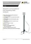
NARDA
Safety
Test
Solutions
S.r.l. Socio Unico
Sales & Support:
Via Leonardo da Vinci, 21/23
20090 Segrate (MI) - ITALY
Tel.: +39 02 2699871
Fax: +39 02 26998700
Manufacturing Plant:
Via Benessea, 29/B
17035 Cisano sul Neva (SV)
Tel.: +39 0182 58641
Fax: +39 0182 586400
http://www.narda-sts.it
User’s Manual
PMM 6630
RF POWER SENSOR
SERIAL NUMBER OF THE INSTRUMENT
You can find the Serial Number on the ID label. It is in the form: 000XY00000.
Document 6630EN-00704 – Copyright © PMM 2009
REMARK:
® Names and Logo are registered trademarks of Narda Safety Test
Solutions GmbH and L3 Communications Holdings, Inc. – Trade names
are trademarks of the owners.
If the instrument is used in any other way than it is described in this
Users Manual, it may become unsafe.
Before using this product, the related documentation must be read
carefully and fully understood to familiarize with all the safety
prescriptions.
To ensure the correct use and the maximum safety level, the User shall
know all the instructions and recommendations contained in this
document.
This product is a Safety Class III instrument according to IEC
classification and has been designed to meet the requirements of
EN61010-1 (Safety Requirements for Electrical Equipment for
Measurement, Control and Laboratory Use).
This product has a Pollution Degree II normally only non-conductive
pollution occurs. Occasionally, however, a temporary conductivity caused
by condensation must be expected.
The information contained in this document is subject to change without
notice.
2
PMM 6630 User’s Manual
KEY TO THE ELECTRIC AND SAFETY SYMBOLS
This is an high quality instrument designed to provide for many
years of reliable service. Nevertheless, even this product will
eventually become obsolete. When that time comes, please
remember that electronic equipment must be disposed of in
accordance with local regulations. This product conforms to the
WEEE Directive of the European Union (2002/96/EC) and belongs
to Category 9 (Monitoring and Control Instruments). You can
return the instrument to us free of charge for proper environment
friendly disposal. You can obtain further information from your
local NARDA Dealer or by visiting our website at www.nardasts.it .
Warning,
shock
danger
of
electric
Earth
Read
carefully
the
User’s
Manual and its instructions,
pay attention to the safety
symbols
Unit Earth Connection
Earth Protection
Equipotential
KEY TO THE SYMBOLS USED IN THIS DOCUMENT:
DANGER
The DANGER sign draws attention to a
potential risk to a person’s safety. All the
precautions must be fully understood and
applied before proceeding
WARNING
The WARNING sign draws attention to a
potential risk of damage to the apparatus
or loss of data. All the precautions must be
fully
understood
and
applied
before
proceeding
CAUTION
The CAUTION sign draws attention against
unsafe
practices
for
the
apparatus
functionality
NOTE:
The NOTE draw attention to important
information
PMM 6630 User’s Manual
3
Contents
Page
Safety considerations and instructions …………………… 7
EC Conformity Certificate………………………………………. 8
1 General
1.1 Documentation........................................................
1.2 Introduction….....................................………………………
1.3 Standard Accessories...............................................
1.4 Other equipment available.........................................
1.5 Specifications………….................................................
1.6 PMM 6630 Connectors.………………….……………………………….
1.7 PMM 6630 ID Label………………………........................…….
Page
10
10
11
11
12
14
14
2 Operation
2.1 Foreword……............................................................
2.2 Inspection……………....................................................
2.3 Ambient…………………..................................................
2.4 Return for service…………...........................................
2.5 Cleaning.................................................................
2.6 Installation and use…………...................…...................
2.7 Functional description…….……………...........................….
2.8 Power signals of dangerous intensity …….....................
2.9 Remove PMM 6630 from the setup.……………................
Page
16
16
16
17
17
18
24
24
25
3 Win6630 Operating Instructions
3.1 Foreword………………..................................................
3.2 PC minimum requirements ……….....……………….............
3.3 Installation.……………………........……………………………………..
3.4 Running Win6630……………...…...................................
3.5 Main window contents..............................................
3.5.1 Title bar……………………………..…………………...................
3.5.2 Main window…………………………………………….………………..
3.5.3 Setting menu…….………………………………………...............
3.5.3.1 Settings………..………………...…………………..................
3.5.3.2 Preference.……….……….………………………….................
3.5.3.3 ? (Info)................…………………………………….............
3.5.3.4 Frequency setting……………..……….……………..............
3.5.3.5 Unit setting………………………………….…………….............
3.5.3.6 HOLD / RUN………………………………………....................
3.5.3.7 EXIT…………………………………………………......................
3.6 Uninstalling Win6630…………..…………………………..............
3.7 Uninstalling the driver of PMM 6630.…........................
Page
28
28
29
32
33
33
34
34
35
38
38
39
39
39
39
40
41
4
PMM 6630 User’s Manual
4 Communication protocol
Page
4.1 Disclaimer ………….……………….................................. 42
4.2 Protocol..……....................................................... 42
5 Accessories
5.1 Foreword............................................................
5.2 Inspection..........................................................
5.3 Ambient.............................................................
5.4 Return for service................................................
5.5 Cleaning.............................................................
5.6 6630-USB Cable…………………………………………………….….
5.7 PMM 6630FOA (optional)…………………………………………..
Page
46
46
46
47
47
48
50
PMM 6630 User’s Manual
5
Figures
Figure
Page
1-1
1-2
1-3
1-4
1-5
2-1
5-1
5-2
5-3
5-4
5-5
10
11
14
14
14
24
48
50
52
52
52
PMM 6630 ………………………………………..…………………………
PMM 6630FOA……………………………………………………………..
PMM 6630 Front view.………………………………………………..
PMM 6630 Rear view .………………………………………………..
PMM 6630 Side view.…………………………………………………..
PMM 6630 Inducted immunity set block diagram………
6630-USB Cable…..……………………………………………………..
PMM 6630FOA……………………………………………………………..
PMM 6630FOA Front view.………………………………………….
PMM 6630FOA Rear view .………………………………………….
PMM 6630FOA Label with Serial Number…………………..
Tables
Table
Page
1-1
1-2
1-3
4-1
4-2
5-1
5-2
5-3
12
14
14
43
44
48
51
56
Specifications of PMM 6630……………..………….....………..
Power ON Led..………………………………………………………….…
Measuring range / PC connection Led………………………..
Query Commands …………………………………………............
Setting Commands ……………………………………………………..
Specifications of 6630-USB Cable…………………….………..
Specifications of PMM6630FOA………………………….……….
LEDs status…………………………………………………………………..
6
PMM 6630 User’s Manual
SAFETY RECOMMENDATIONS AND INSTRUCTIONS
This product has been designed, produced and tested in Italy, and it left the
factory in conditions fully complying with the current safety standards. To
maintain it in safe conditions and ensure correct use, these general instructions
must be fully understood and applied before the product is used.
• When the device must be connected permanently, first provide effective
grounding;
• If the device must be connected to other equipment or accessories, make
sure they are all safely grounded;
• In case of devices permanently connected to the power supply, and lacking
any fuses or other devices of mains protection, the power line must be
equipped with adequate protection commensurate to the consumption of all
the devices connected to it;
• In case of connection of the device to the power mains, make sure before
connection that the voltage selected on the voltage switch and the fuses are
adequate for the voltage of the actual mains;
• Devices in Safety Class I, equipped with connection to the power mains by
means of cord and plug, can only be plugged into a socket equipped with a
ground wire;
• Any interruption or loosening of the ground wire or of a connecting power
cable, inside or outside the device, will cause a potential risk for the safety of
the personnel;
• Ground connections must not be interrupted intentionally;
• To prevent the possible danger of electrocution, do not remove any covers,
panels or guards installed on the device, and refer only to NARDA Service
Centers if maintenance should be necessary;
• To maintain adequate protection from fire hazards, replace fuses only with
others of the same type and rating;
• Follow the safety regulations and any additional instructions in this manual to
prevent accidents and damages.
PMM 6630 User’s Manual
7
Declaration of EC Conformity
(in accordance with the Directives: EMC 89/336/EEC and Low Voltage 73/23/EEC)
This is to certify that the product: PMM 6630 RF Power Sensor 9 kHz – 3 GHz
Produced by: NARDA S.r.l.
Safety Test Solution
Via Benessea 29/B
17035 Cisano sul Neva (SV) - ITALY
complies with the following European Standards
Safety: CEI EN 61010-1 (2001)
EMC: EN 61326-1 (2007)
This product complies with the requirements of the Low Voltage Directive
2006/95/CE and with the EMC Directive 2004/108/CE.
NARDA S.r.l.
8
PMM 6630 User’s Manual
This page has been intentionally left blank
PMM 6630 User’s Manual
9
1 – General
1.1
Documentation
This Manual includes:
• Questionnaire to send back together with the instrument
to service.
• Check list of supplied accessories.
1.2
Introduction
The PMM 6630 is a simple and easy to use RF power
measuring instrument.
It is very suitable in EMC applications to calibrate CDNs
and CLAMPs for conducted and induced immunity tests,
and to measure the power of RF signals forwarded to
antennas or GTEMs cells.
Forward and reflected powers can be measured by using a
directional coupler.
The internal compensation prevents temperature drifting
effects.
The instrument is supplied together with drivers for any
WindowsTM environments. Just execute WindowsTM software
and get your reading (dBm, W and Vrms) into the PC
monitoring window.
If you are using PMM immunity software (conducted or
radiated) all drivers are already embedded and ready to
use.
Fig. 1-1 PMM 6630
Document 6630EN-00704 – © NARDA 2009
10
PMM 6630 User’s Manual
The PMM 6630 also can work with the optional accessory
PMM 6630FOA that allows to convert the USB signal of the
power sensor into fiber optic compatible signal. It is often
beneficial to use noise immune fibre optic cable instead of
USB cable in environments where is requested a low noise
level or simply to extend the link; moreover, the optic link
is immune to interferences caused by high field level.
The PMM 6630FOA is linked to the USB port of any
Personal Computer through the USB-OC Optical USB
Converter supplied with the unit.
Fig. 1-2 PMM 6630FOA
1.3
Standard
accessories
Accessories and documents supplied with PMM 6630
1.4
Other available
accessories
Other equipment available from PMM to use in conjunction
with the PMM 6630 RF power meter:
• PMM 3030 (3 GHz) – PMM 3010 (1 GHz) EMI Signal
Generator
• PMM 6000N Wideband RF Power Amplifier
• PMM 6630FOA Fiber Optic Adapter
•
•
•
•
•
6630-USB Cable;
CD-ROM with Software;
User’s Manual
Calibration Certificate
Service form
PMM 6630 User’s Manual
11
This condition applies to all specifications:
• The operating ambient temperature range must be -10°
to +40 °C.
1.5
Specifications
TABLE 1-1 Specifications of the PMM 6630
Frequency range
9 kHz to 3 GHz
Power
measurement
range
100 nW to 1 W (-40 dBm to +30 dBm)
Max. Power
2 W peak envelope, max 300 ms
RF Connector
N-male 50 Ω
Max. SWR
(25°C ± 10 °C)
10 kHz to 300 kHz
>300 kHz to 100 MHz
>100 MHz to 1 GHz
> 1 GHz to 3 GHz
10 kHz to 3GHz
1.10
1.05
1.10
1.25
from +30 dBm to -9 dBm
1.20
from < -9 dBm to -40 dBm
Power linearity
(25°C ± 10 °C)
-40 dBm to 30 dBm at 50 MHz:
Measurement
Accuracy 1, 2
(25°C ± 10 °C)
< 0,35 dB
Measuring ranges High
+30 dBm to -9 dBm
(automatic
Low
-9 dBm to -40 dBm
change)
Switching point Hysteresis
Temperature
operating range
12
-10°C to 50°C
PMM 6630 User’s Manual
0,2 dB
1 dB typical
Power Supply
5 VDC – 100 mA (through USB Port)
PC Interface
USB 1.0
System
requirements
Windows XP, Vista
Size
30 x 30 x 95 mm (WxHxD)
Weight
0.12 kg
1.
2.
1.1
2.0
Max SWR source = 1.25
Calculated with worst calibration uncertainties to the calibration factor of 0,17 dB.
PMM 6630 User’s Manual
13
1-RF input
1.6
Connectors
Fig. 1-3 PMM 6630 Front view
1- Fischer connector cable
input
2-Led: Power ON Led
3-Led: Measuring range/
PC connection
Fig. 1-4 PMM 6630 Rear view
TABLE 1-2: Power ON Led
Led status
Green
OFF
Meaning
PMM 6630 ON
PMM 6630 OFF / Disconnected
TABLE 1-3: Measuring range/ PC connection Led
Led status
Green
OFF
Red
Meaning
PMM 6630 in Low range, from -9 dBm to -40 dBm
PMM 6630 in High range, +30 dBm to -9 dBm
Communication fault
1.7
ID Label
PMM 6630
Fig. 1-5 PMM 6630 Side view
14
PMM 6630 User’s Manual
Legend: 1-Year of production
2-Serial Number
This page has been intentionally left blank
PMM 6630 User’s Manual
15
2 – Operation
2.1
Foreword
None
2.2
Inspection
Once
-
received the instrument, please check:
packaging integrity
instrument and accessories integrity
contents, according to the check list attached to this
manual
Contact your Dealer immediately if something is
damaged or missed.
2.3
Ambient
Store instrument and accessories in clean, dry environment
free of dust and acid vapours.
Follow requirements for temperature and humidity:
Operation:
• Temperature
• Humidity
-10° to +40° C
< 90% RH
Storage:
• Temperature
• Humidity
1
Document 6630EN-00704 – © NARDA 2009
16
PMM 6630 User’s Manual
-20° to + 70° C
< 95% RH
2.4
Return for
service
When the instrument needs to be sent to NARDA for
repairs please complete the questionnaire enclosed with
this Operating Manual making sure you fill in all the details
relative to the service requested.
In order to minimize repair time, please describe the
nature of the failure. If the failure occurs only under certain
conditions, please provide details on how we may recreate
the same condition in order to identify the fault.
If possible, please reuse the original packaging, making
sure the instrument in wrapped in heavy paper or plastic.
Alternatively, use a strong box filled with shockproof
material, place enough material all around the equipment
so that the unit is stable and firmly blocked inside the box.
Mark the box: FRAGILE HANDLE WITH CARE.
2.5
Cleaning
To clean the equipment use only dust-free, non-abrasive
dry cloths.
To avoid damage never use any kind of solvent, acid,
or similar to clean the instrument.
PMM 6630 User’s Manual
17
2.6
Installation
and use
PMM 6630 is supplied through USB port PC. The RF Input
connector is located on the front; the Fisher connector (for
PC connection) and Leds on the rear.
Connect the PMM 6630 to the PC only once the
software Win6630 supplied in the CD-ROM has been
successfully installed.
Do not connect the Data-Supply cable by applying
force to the cable directly: this may damage the
connection. Always hold firmly the connectors with
your fingers to connect the cable.
Presence of dust, dirt or particles of any nature on
the 4 poles connector surfaces must be carefully
prevented.
To avoid damage, the arrow marked on the external
part of the Data-Supply connector must match to the
PMM 6630 connector.
Once Win6630 has been successfully installed (see Chapter
3), connect the Data-Supply cable (supplied) to the PMM
6630 respecting the connection sense; make sure to
tighten the Fisher cable connector to the PMM 6630
connector.
18
PMM 6630 User’s Manual
Connect the other cable end to the USB port PC.
When the PMM 6630 is on, the Leds show the operating
mode (see chapter 1).
If the driver is not already installed a message informing
that new hardware has been found will appear and a
guided installation will be started:
Do not allow connection to Windows Update by checking
“No, not now” and click “next”
PMM 6630 User’s Manual
19
Select “Install from a list or specific path” and click “next”
Select options as in the picture and click “browse” to select
the directory containing the requested files:
The folder “USB-WIN-XP” which includes driver for
Windows XP and Vista is in the following path:
c:\Programmi\Win6630\Win-XP. Select it and click
“OK”
20
PMM 6630 User’s Manual
Click “next” to start the installation.
Click “continue”
PMM 6630 User’s Manual
21
Click “Finish” to complete the driver installation; the new
hardware is now ready to use.
22
PMM 6630 User’s Manual
Connect the PMM 6630 RF input connector to the source.
Tighten the PMM 6630 N-type RF connector input
connector
to
the
source
connector.
Loose
connections may cause wrong readings.
PMM 6630 User’s Manual
23
2.7
Functional
description
The following block diagram represents the typical
configuration of inducted immunity tests where the PMM
6630 measure the power applied to the CDNs.
Fig. 2-1 Inducted immunity set block diagram
2.8
Power signals
of dangerous
level
Do not apply to the PMM 6630 power levels exceeding
the max. allowed value (see Table 1.1).
24
PMM 6630 User’s Manual
2.9
Remove
PMM 6630
from the setup
Uninstalling the driver is not required to remove the
PMM 6630 from the setup.
Press
to close the Win6630 Software.
Disconnect the USB Cable from the PC.
Do not disconnect the USB Cable by applying force to
the cable directly: this may damage the connection.
Always hold firmly the connectors with your fingers
to disconnect the cable.
Disconnect the PMM 6630 from the RF source.
PMM 6630 User’s Manual
25
Disconnect the Fisher connector and the Data-Supply cable
from the Power Sensor.
Disconnect the Data-Supply cable by applying force to
the cable directly: this may damage the connection.
Always hold firmly the connectors with your fingers
to disconnect the cable.
26
PMM 6630 User’s Manual
This page has been left blank intentionally
PMM 6630 User’s Manual
27
3 –Win6630 Operating instructions
3.1
Foreword
This chapter is the installation and operation guide of the
PC Software Win6630 supplied with the PMM 6630 RF
Power Sensor.
3.2
PC minimum
requirements
•
•
•
•
Processor: Pentium
16 Mb RAM
10 Mb free space on hard disk;
Operating system Windows™, XP/Vista.
Software updates can be downloaded from the web
page www.narda-sts.it.
2
Document 6630EN-00704 – © NARDA 2009
28
PMM 6630 User’s Manual
3.3
Installation
Do not connect the PMM 6630 to the PC until the
installation is completed.
Insert the Win6630 CD into the PC CD-ROM driver.
In Computer Resources double click on the corresponding
CD-ROM driver.
To start the installation double click on the Win6630 icon.
In Windows Vista most programs are blocked for
computer protection. To start the installation
correctly it might be necessary to authorize the
operation.
PMM 6630 User’s Manual
29
The installation folder must be specified. Click Next to
confirm the default folder or Change to modify.
Click Next to proceed installing.
30
PMM 6630 User’s Manual
The installing status is displayed then:
Click Finish to complete and exit the installer.
The folder Win6630 are created under Programs with the
icon Win6630 on desktop.
PMM 6630 User’s Manual
31
3.4
Running
Win6630
Connect the PMM 6630 to PC an click the icon on desktop.
Alternatively (Windows
Win6630, Win6630.
XP):
Start,
Windows Vista: Click
Win6630, Win6630.
Windows
(
All
Programs,
),
Programs,
This window is displayed first:
This message appears when PMM 6630 is not connected or
the communication is not established:
32
PMM 6630 User’s Manual
3.5
Main window
contents
Main window:
1. Title bar
2. Main window
3. Measurements and settings selections
4. Frequency setting
5. Unit setting;
6. Hold/run readings;
7. Exit and quit the program
3.5.1
Title bar
The title bar shows the Win6630 icon, the current RF power
measurement, the measuring unit and the Software name.
The control buttons allow to minimize to icon and exit the
program.
When minimizing the main window the information is
displayed in the Windows application bar at the bottom of
screen.
PMM 6630 User’s Manual
33
3.5.2
Main window
The main window displays:
- Power data.
-50.91
- Measuring unit (see “Unit setting”)
dBm
- Correction frequency (see par. “Frequency setting”)
Default: Freq: 50.00 MHz
- Average, Correction Factor e Offset
(see “Setting menu/Settings”)
Avg: 1
CorFact: 100.0%
Offset: 0.0 dB
3.5.3
Setting menu
Commands:
- Settings: Average, Correction Factor, Offset.
- Preference: program skin.
- ? (Info): software and product information.
34
PMM 6630 User’s Manual
3.5.3.1
Settings
Settings options:
- Offset: The value represents the compensation of the
eventual attenuation between the device under test and
the Power Sensor.
, confirm with
Enter a new offset value
close the window with
and
.
- Average: setting of the number (1, 4, 16, 32, 64, 128,
256, 512 and 1024) of readings to calculate the arithmetic
average (AVG).
In the example, the average value of the last 4 field
readings will be displayed.
Press
to close the Average window .
PMM 6630 User’s Manual
35
- Correction Factors expressed in %, for each frequency.
The displayed level is the incident power corrected by this
factor.
At the first run the correction factor is disabled; to enable,
tick on “Click to enable Correction Factor”.
Press
to enter a Correction Factor. The following
window will be displayed:
The setting displayed at the first run is the default
one; the last setting will be displayed then.
36
PMM 6630 User’s Manual
Enter a frequency correction factor between 80%
and 120%.
Set
the
and
Frequency
the
Correction Factor
; press
to store the values on the table and close the window with
.
A warning message will appear if the new frequency value
is already present in the table.
To cancel the Correction Factor, click on the corresponding
line, that turns blue, then press
Correction Factor value.
PMM 6630 User’s Manual
to cancel the
37
3.5.3.2
Preference
Selection of different colour combinations of the main
window:
Background / readings and units
-
Blue/Gray
Grey/White
Grey/Yellow
Black/Yellow
Black/Green
Black/White
The settings colours of Freq, Avg, CorFact and Offset
will be displayed accordingly.
3.5.3.3
? (Info)
Contents:
- Info: current PMM 6630 firmware version and date,
Software version and serial number
- About: Manufacturer information.
38
PMM 6630 User’s Manual
3.5.3.4
Frequency
correction
setting
This setting in MHz recalls the corresponding frequency
correction factor stored in the PMM 6630 memory.
The frequency is displayed with three decimals, with max.
resolution of 0.001 MHz. Press SET to enter the frequency
value.
3.5.3.5
Unit setting
Click on the buttons to change the measuring units:
- dBm:
- nW:
- mVrms:
3.5.3.6
HOLD / RUN
Press HOLD to hold the last reading.
Click on the button to toggle from HOLD to RUN
The button XYZ/TOT is active even when in HOLD.
If the program is ended when in HOLD mode, it will
restart in RUN mode.
3.5.3.7
EXIT
Press EXIT to end the program. The current settings are
saved and will be recalled at the next start.
PMM 6630 User’s Manual
39
3.6
Uninstalling
Win6630
Disconnect the USB cable (the
disconnection” is unnecessary).
procedure
of
“safe
Windows XP: click Start
in Windows Vista: click Windows
Then All Programs, Win6630, Uninstall Win6630.
If the Uninstaller is not available:
- Disconnect the USB cable (the procedure of “safe
disconnection” is unnecessary).
- Click Start, Settings, Control Panel and Add or
Remove Programs (Programs and functions for
Windows Vista).
Find Win6630
instructions.
then
click
Remove
and
follow
the
When asked if removing the shared files, answer NO
to prevent other programs not to run correctly.
40
PMM 6630 User’s Manual
3.7
Uninstalling
PMM 6630 Driver
Right click My computer to access Properties
Select Hardware and Device Manager.
Click + to expand Port (COM and LPT).
Right click USB Serial Port (COM) then click Uninstall
Click OK to end.
Once the uninstall is completed the peripheral USB Serial
Port (COM) will be removed.
PMM 6630 User’s Manual
41
4 - Communication protocol
4.1
Disclaimer
This chapter provides the information required to control
the PMM 6630 via the Data-Supply cable connected to a PC
and by means of user’s own PC software applications.
Narda STS S.r.l supports the correctness of the information
only, and disclaim for any consequence the use of such
information may cause to anybody. The inclusion of
Narda’s communication protocol into user’s or third party
software is entirely at the user’s risks and responsibility. In
no way Narda STS S.r.l shall be liable for damages of any
kind consequent to the use of the information provided in
this chapter.
4.2
Protocol
The commands are sent to the device through FTDI driver
in USB mode (USB 1.1 / 2.0) or virtual serial port whose
parameters are:
•
•
•
•
•
Bits per second: 9600
Data Bits: 8
Parity: Nessuna
Stop Bits: 1
Flow control: None
The commands are composed by an ASCII string delimited
by “#” (0x23) and “*” (0x2A)
Commands must start with “#63”.
The answer can be either in ASCII or Binary, according to
the command sent. The first character is always like the
character sent, and can be used as control marker or
synchronization for the answer.
The available commands are of two categories:
• Query COMMANDs
• Setting COMMANDs
The commands have this format:
#63Qcommand(parameters)* where::
# = command string start;
63 = string always present;
Q = ? for query commands;
S for setting commands;
Command = command string;
(parameters) = setting parameters
present);
* = command string end.
Document 6630EN-00704 – © NARDA 2009
42
PMM 6630 User’s Manual
value
(where
TABLE 4-1 Query COMMANDs
?v
Release
#63?v* sends back a string containing information about
model, release and date of firmware.
Example of reply
6630:A.00.01/08;"
?p
Power
to
the
command
#63?v*:
"PMM
#63?p* sends back a string containing power data expressed in
dBm.
When this command is sent while the 6630 is switching the
ADCs, the data is meaningless, thus the 6630 replies with the
string: " *** ".
Example of reply to the command #63?p*: "-4.97 dBm"
?m
Average of
4 measurements
#63?m* sends back a string containing the average power of 4
measurements. As for power data, it is expressed in dBm.
When the 4 last data are taken from different ranges, the
average is meaningless, thus the 6630 replies with the string: "
*** ".
Example of reply to the command #63?m*: "-4.97 dBm"
?M
Average of
16 PWR’s
#63?m* sends back a string containing the average power of
16 measurements. As for power data, it is expressed in dBm.
When the 16 last data are taken from different ranges, the
average is meaningless, thus the 6630 replies with the string: "
*** ".
Example of reply to the command #63?M*: "-4.97 dBm"
?s
Serial Number
#63?s* sends back a string containing the serial number of the
6630.
Example of reply to the command #63?s*: "123456789"
?f
Frequency
#63?f* sends back a string containing the frequency at which
the 6630 is set. Note that this frequency value establishes the
correct calibration of the 6630 at that particular frequency only,
thus when this value has not the appropriate setting, the 6630
measurements are meaningless. It is expressed in kHz.
Example of reply to the command #63?f*: "f:1200 kHz"
When frequency value is set to 0 kHz no frequency correction
factors are computed.
Example of reply to the command when frequency is set to 0
kHz #63?f*: "f:dis"
PMM 6630 User’s Manual
43
Sf
Set Frequency
TABLE 4-2 Setting COMMANDs
#63Sf<value>* sets the frequency(<value>) to which
refer the correction factor. The frequency is expressed in
kHz.
Once the 6630 has received and recognized this command,
all measurements will be corrected using the factor stored
at factory and related to that frequency.
Sending a frequency value of 0 kHz disables the frequency
correction factor function.
Example of command #63Sf9*: Set the referring
frequency to 9 kHz and reply: f:9 kHz (This value is the
PMM 6630 minimum frequency)
Example of command #63Sf3000000*: Set the referring
frequency to 3 GHz and reply: f:3000000 kHz (This value
is the PMM 6630 maximum frequency)
Example of command #63Sf0*: Disable
correction factor function and reply: f:dis
44
PMM 6630 User’s Manual
frequency
This page has been intentionally left blank
PMM 6630 User’s Manual
45
5 - Accessories
5.1
Foreword
This chapter explains how to use the accessories of PMM
6630.
The following general indications apply to all accessories.
5.2
Inspection
Check the packaging integrity.
5.3
Ambient
If anything is found damaged or missed, immediately
contact your Dealer.
Check the accessories with reference to the packing
list included in the package.
Store the accessories in clean, dry environment free of
dust and acid vapours.
Follow requirements for temperature and humidity:
Operation:
• Temperature
• Humidity
-10° to +50° C
< 90% RH
Storage:
• Temperature
• Humidity
-20° to + 70° C
< 95% RH
3
Document 6630EN-00704 – © NARDA 2009
46
PMM 6630 User’s Manual
5.4
Return for
service
Every part of the accessories can only be replaced by
NARDA, when the instrument needs repair or is
malfunctioning, please contact the NARDA Support center.
When an accessory needs to be sent to NARDA for repairs
please complete the questionnaire enclosed with this
Operating Manual making sure you fill in all the details
relative to the service requested.
In order to minimize repair time, please describe the
nature of the failure. If the failure occurs only under certain
conditions, please provide details on how we may recreate
the same condition in order to identify the fault.
If possible, please reuse the original packaging, making
sure the accessory is wrapped in heavy paper or plastic.
Alternatively, use a strong box filled with shockproof
material, place enough material all around the equipment
so that the unit is stable and firmly blocked inside the box.
Mark the box: FRAGILE HANDLE WITH CARE.
5.5
Cleaning
To clean the equipment use only dust-free, non-abrasive
dry cloths.
To avoid damage never use any kind of solvent, acid,
or similar to clean the instrument.
PMM 6630 User’s Manual
47
5.6
6630-USB Data-Supply Cable
Fig. 5-1 6630-USB Data-Supply Cable
TABLE 5-1 Specifications of the 6630-USB Data-Supply Cable
Length
1,8 m
USB Connector
Type A Male
Multipolar Connector
4 Poles
Such devices like USB Hubs and USB cable
extensions may not work properly. Connect the PMM
6630 to the PC directly with the supplied 6630-USB
cable.
Front view
Connector 4 poles
Rear view
USB Type A Male
48
PMM 6630 User’s Manual
This page has been intentionally left blank
PMM 6630 User’s Manual
49
5.7
PMM 6630FOA Fiber Optic Adapter (Optional)
Introduction
The PMM 6630FOA Fiber Optic Adapter is an optional
accessory of the PMM 6630 RF Power Sensor.
The PMM 6630FOA is a fiber optic adapter that allows to
convert the USB signal of the PMM 6630 into fiber optic
compatible signal; it is often beneficial to use noise
immune fibre optic cable instead of USB cable in
environments where a low noise level is required or simply
to extend the link; moreover, the optic link is immune to
interferences caused by high level field.
The PMM 6630FOA is linked to the USB port of any
Personal Computer through the USB-OC Optical USB
Converter supplied with the unit.
The power supply is provided by an internal Li-Ion battery
for up to 8 hours of continuous operation; the internal
battery can be recharged with the battery charger supplied
with the unit.
The PMM 6630FOA has been designed for EMC applications
and can be driven by Win6630 or PMM Immunity Test
software or by a software developed directly by the user.
Fig. 5-2 PMM 6630FOA
50
PMM 6630 User’s Manual
Standard
accessories
and
documents
The accessories and documents enclosed with
instrument PMM 6630FOA are:
• PMM 6630FOA Fiber Optic Adapter;
• USB-OC Optical USB Converter;
• FO-6630/10 Cable, Fiber Optic Cable (10m);
• Battery charger + international plug adapter;
• Operating Manual + repair request form;
• Calibration Certificate.
the
Optional
accessories
The following accessories can be ordered separately:
• FO-6630/10 Cable, fiber optic 10 m;
• FO-6630/20 Cable, fiber optic 20 m;
• FO-6630/40 Cable, fiber optic 40 m.
Specifications
This condition applies to all specifications:
• The operating ambient temperature range must be -10°
to +50 °C.
TABLE 5-2 Specifications of the PMM 6630FOA
Output
connector for optic fibre
Maximum length of optic fibre, 80 meters
Input
Connector 4 poles
Compatibility
with PMM 6630 RF Power Sensor
Power Supply
Internal battery 3,7 V – 1,8 Ah Li-Ion, rechargeable
Operating time
8 hours
Recharging time
4 hours
Temperature
operating range
-10°C to 50°C
Storing
temperature
from -20 to +70°C
Dimensions
40 x 40 x 61 mm (WxHxD)
Weight
168 g
PMM 6630 User’s Manual
51
Housing
The PMM 6630FOA is allocated in a small rectangular
housing; on the front panel is located the 4 poles connector
for 6630 matching; on the rear panel there are connection
for the fiber optic, connector for the battery charger, power
switch, LEDs for checking about charging and ID label for
immediate identification;
Legend:
4 poles Connector
Fig. 5-3 PMM 6630
Front view
Legend:
1- Optic link
2- Green Led
3- Red Led
4- Connector for
battery charger
5- Power switch
6- ID Label
Fig. 5-4 PMM 6630
Rear view
Legend:
7- Serial Number
Fig. 5-5 PMM 6630FOA
Label with Serial Number
52
PMM 6630 User’s Manual
Installation
Make sure USB-OC converter driver is installed in
your PC.
Connect the PMM 6630FOA to the PMM 6630 only
once the software has been successfully installed.
Connect the Fisher connector of the PMM 6630FOA
by holding firmly it with your fingers.
Presence of dust, dirt or particles of any nature on
the 4 poles connector surfaces must be carefully
prevented.
To avoid damage, the arrow marked on the external
part of the connector must match to the PMM 6630
connector.
Connect the PMM 6630FOA connector to the Power Sensor
respecting the connection sense.
Place the units on a stable surface.
PMM 6630 User’s Manual
53
Make sure USB-OC converter driver is installed in your PC;
connect the converter supplied with the unit to the first
available USB port
Sometime devices like USB Hubs or USB cable
extensions may not work properly. In such
occurrences simply connect the USB-OC to the PC
directly.
Connect the supplied fiber optic to the FIBER OPTIC
connector of the PMM 6630FOA taking care that the spigot
matches the housing. Connect the other end of the fiber
optic to the USB-OC.
Connect the PMM 6630 RF input connector to the source.
Tighten the PMM 6630 N-type RF connector input
connector
to
the
source
connector.
Loose
connections may cause wrong readings.
54
PMM 6630 User’s Manual
Power supply and
battery charging
To charge the unit it’s needed to switch OFF the unit.
The PMM 6630FOA is supplied by internal rechargeable LiIon battery which can be recharged with the battery
charger supplied with the unit.
Make a full charging cycle before using the Optic
Adapter for longest battery operation time.
The battery charger has an internal output current
limiter in case of overload when connecting to the
mains.
The complete charging cycle of a new battery lasts 4
hours.
Battery charger:
output: DC, 12 V, ~ 1.25A
Connector:
-
+
To charge the unit it’s needed to switch OFF the unit at
first; connect the battery charger to the AC mains BEFORE
connecting it to the connector labelled CHG of the PMM
6630FOA. The LEDs show how charging progresses,
according to what specified in Table 5-3.
PMM 6630 User’s Manual
55
Use of
PMM 6630FOA
with PMM 6630
During the use, it is suggest to disconnect the PMM
6630FOA from the battery charger.
Once PMM 6630FOA has been successfully installed to the
PMM 6630, the fiber Optic Adapter can be switched ON by
power switch (also the PMM 6630 is then automatically
switched on).
When switched ON, both LEDs of the PMM 6630FOA are
OFF; one of the two green LEDs on PMM 6630 body turns
ON, after two seconds the other green led turns also ON.
The PMM 6630 and PMM 6630FOA are ready to be used.
If there are communications problems between the PMM
6630FOA and the software, it will be displayed an error
message on the screen.
During the use, the Red Led of the PMM 6630FOA turns ON
to warn the Operator that the instrument is running out of
battery; the residual autonomy during measurements is of
15 minutes.
Check the Led status as per the table below.
Switch
ON*
OFF
TABLE 5-3: LEDs Status
Red
ON
the instrument is running out of battery.
Green
OFF
Battery recharging completed
Green
ON
the battery is under charge
Red
ON
error of charging
* disconnect the PMM 6630FOA from the battery charger.
56
PMM 6630 User’s Manual
Application
The wide frequency range and small size allow for using
the PMM 6630 and PMM 6630FOA in EMC applications for
monitoring the field strength during radiated and
conducted immunity tests in Open Area Test Sites,
TEMs/GTEMs and Anechoic Chambers.
PMM 6630 User’s Manual
57
Remove
PMM 6630 and
PMM 6630FOA
from the setup
Uninstalling the driver is not required to remove the
PMM 6630, PMM 6630FOA and USB-OC from the
setup.
Close the running Software.
To remove the PMM 6630FOA from the setup is
needed to switch OFF the unit.
Disconnect the USB-OC from the PC.
Do not disconnect the USB-OC by applying force to
the fiber optic directly: this may damage the
connection. Always hold firmly the adapter with your
fingers to disconnect.
Disconnect the PMM 6630 from the RF source taking care to
the fiber optic adapter with other hand.
58
PMM 6630 User’s Manual
Place the units on a stable surface.
Disconnect the PMM 6630FOA from the Power Sensor
holding it from the ring nut.
Don’t disconnect the PMM 6630FOA applying huge
force to the connector: this could damage the
connection on both side. Always hold firmly the
connector at ring nut with your fingers, being sure it
has been completely unscrewed at first.
PMM 6630 User’s Manual
59
Microsoft®, WindowsTM, WordTM, ExcelTM are marks of the Microsoft Corporation.
NARDA s.r.l. reserves the right to reproduce and translate, even only partially, this document.
Warning: This Manual may be subject to modification without prior notice.
.
60
PMM 6630 User’s Manual