1
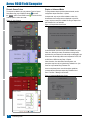
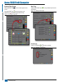
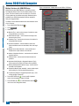
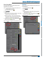
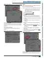
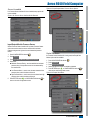
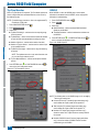
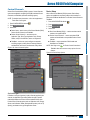
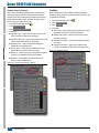
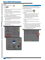
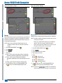
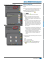
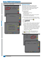
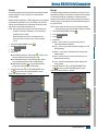
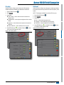
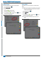
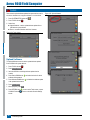
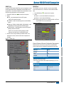
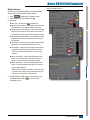
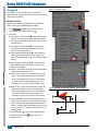
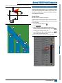
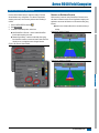
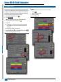
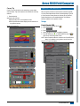
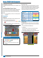
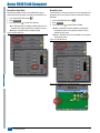
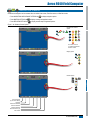
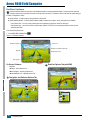
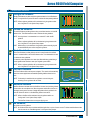
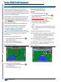
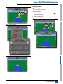
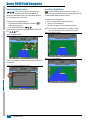
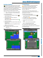
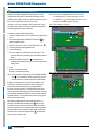
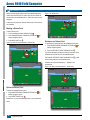
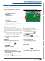
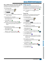
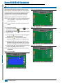
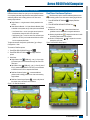
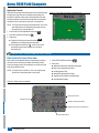
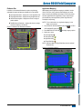
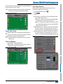
Aeros 9040 Field Computer Figure 6-25: Lateral Implement Offset Distance HOME Lateral implement offset distance is used to enter the distance from the center line of the machine to the center of the implement. When on-screen mapping shows no overlap or gap, yet field application produces an overlap or gap consistently to only one side in the direction of travel, an adjustment to the lateral implement offset distance should be calculated and made to the implement offset distance value. INTRODUCTION LATERAL IMPLEMENT OFFSET DISTANCE ADJUSTMENT FULL SCREEN If using a self-propelled sprayer or spreader, use the GNSS Offset Adjustment Calculation to calculate the implement offset distance adjustment. If using a pull behind or trailed implement, use the Implement Offset Adjustment Calculation to calculate the implement offset distance adjustment. SETUP NOTE: While using assisted/auto steering, if on-screen mapping shows overlaps and gaps, adjustments may need to be made to the assisted/auto steering settings. GNSS Offset Adjustment Calculation To calculate a GNSS offset adjustment using the same guideline: 2. With assisted/auto steering engaged, drive pass at least 100 feet / 30 meters, and place flags at the draw bar or next to the machine. 3. Turn around and engage assisted/auto steering on pass on the same AB guideline. Place flags at the draw bar or next to the machine, or stop while on the AB guideline next to the flags you placed on pass . GNSS 1. Create a straight AB line. 4. Measure the difference between the flags of pass and pass . 6. Increase or decrease the offset distance as needed dependent on where the field application overlap occurs and the current implement offset direction setting. Field Application Overlap Offset Direction = Left Offset Direction = Right Offset Direction = Right Offset Distance = 0 ft/m To the right of pass Increase distance offset value Decrease distance offset value Increase distance offset value To the left of pass Decrease distance offset value Increase distance offset value Change to implement offset direction to left and increase distance offset value GUIDANCE Current Offset Settings IMPLEMENT 5. Divide the measured distance in half. This difference will be the offset adjustment. APPENDIX RATE CONTROL Figure 6-26: GNSS Offset Distance 98-05304-ENUS R0 55