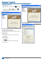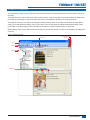
1
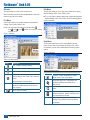
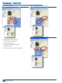
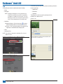
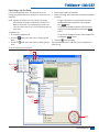
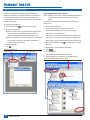
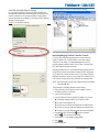
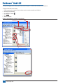
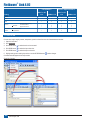
F I E L D WA R E ® L I N K U S E R M A N Software version 4.02 PC cataloging program user manual for Matrix® Pro G v2.x and Matrix® Pro GS v2.5x & v3.x software U A L FIELDWARE® LINK 4.02 Copyrights © 2013 TeeJet Technologies. All rights reserved. No part of this document or the computer programs described in it may be reproduced, copied, photocopied, translated, or reduced in any form or by any means, electronic or machine readable, recording or otherwise, without prior written consent from TeeJet Technologies. Trademarks Unless otherwise noted, all other brand or product names are trademarks or registered trademarks of their respective companies or organizations. Limitation of Liability TEEJET TECHNOLOGIES PROVIDES THIS MATERIAL “AS IS” WITHOUT WARRANTY OF ANY KIND, EITHER EXPRESSED OR IMPLIED. NO COPYRIGHT LIABILITY OR PATENT IS ASSUMED. IN NO EVENT SHALL TEEJET TECHNOLOGIES BE LIABLE FOR ANY LOSS OF BUSINESS, LOSS OF PROFIT, LOSS OF USE OR DATA, INTERRUPTION OF BUSINESS, OR FOR INDIRECT, SPECIAL, INCIDENTAL, OR CONSEQUENTIAL DAMAGES OF ANY KIND, EVEN IF TEEJET TECHNOLOGIES HAS BEEN ADVISED OF SUCH DAMAGES ARISING FROM TEEJET TECHNOLOGIES SOFTWARE. NOTE Photos and illustrations may vary from the actual components provided. This may be due to different installation options, operation modes or production models. Fieldware® Link 4.02 Table of Contents GETTING STARTED 1 REQUIREMENTS1 Recommendations................................................................................................................................................................................................ 1 DOWNLOADING FROM TEEJET.COM 1 INSTALLATION1 Starting the Program............................................................................................................................................................................................ 2 Setting The Program Language....................................................................................................................................... 2 Welcome Screen.....................................................................................................................................................................2 Program Options.....................................................................................................................................................................2 INTERFACE OVERVIEW 3 Menus........................................................................................................................................................................................................................ 4 File Menu........................................................................................................................................................................ 4 Edit Menu........................................................................................................................................................................ 4 View Menu...................................................................................................................................................................... 4 Resources Menu............................................................................................................................................................. 5 Window Menu................................................................................................................................................................. 5 Help Menu...................................................................................................................................................................... 5 Toolbar....................................................................................................................................................................................................................... 6 Catalog Tree View.................................................................................................................................................................................................. 6 Catalog Reorganization................................................................................................................................................... 7 Screen Organization............................................................................................................................................................................................. 7 PROGRAM OPTIONS 9 MANAGING: MACHINE SETTINGS, CLIENTS, FARMS, FIELDS AND JOBS ADDING, VIEWING, DELETING 10 10 Adding New Machine Settings, Clients, Farms, Fields or Jobs....................................................................................... 10 Viewing Machine Settings, Client, Farm, Field or Job Properties................................................................................... 11 Deleting a Profile For Machine Settings, Client, Farm, Field or Job............................................................................... 11 PROFILE OVERVIEW 12 Machine Settings.................................................................................................................................................................................................12 Implement Type............................................................................................................................................................. 12 Section Numbers..................................................................................................................................................................12 ABSC Disabled – Single Section Setup ........................................................................................................................ 13 Straight Implement Type.......................................................................................................................................................13 TeeJet Spreader Implement Type.........................................................................................................................................14 Staggered Implement Type...................................................................................................................................................15 ABSC Enabled – Smartcable or Section Driver Module Setup....................................................................................... 16 Straight Implement Type.......................................................................................................................................................16 TeeJet Spreader Implement Type.........................................................................................................................................17 98-05244-ENUS R1 i Fieldware® Link 4.02 Staggered Implement Type...................................................................................................................................................19 Farm..........................................................................................................................................................................................................................21 Field..........................................................................................................................................................................................................................22 Job.............................................................................................................................................................................................................................24 Duplicating a Job For Reuse......................................................................................................................................... 25 IMPORTING/EXPORTING26 Exporting profiles to the console................................................................................................................................... 26 Jobs With Associated Machine Settings...............................................................................................................................27 Importing/Merging Profiles From the Console................................................................................................................ 27 Machine Settings Availability......................................................................................................................................... 29 CONVERTER30 PRINT PREVIEW ii www.teejet.com 31 Fieldware® Link 4.02 GETTING STARTED REQUIREMENTS INSTALLATION Some Microsoft Windows operating systems may require administrator rights to install this software. Once the installation program has been downloaded: 1. Double-click the TEEJET FIELDWARE LINK icon Microsoft operating systems.........Windows XP Service Pack 3, Windows Vista or Windows 7 2. Follow instructions on installation windows. . Figure 1: TeeJet Fieldware Link Icon Hard drive space..........................200 MB of free space Processor.....................................IBM compatible x86 Pentium class processor, or newer, running at a minimum of 733 MHz Figure 2: Installation Windows Memory.........................................1 GB of RAM Peripheral devices........................USB 2.0 port Peripheral software.......................Microsoft .NET Framework 4 Client profile Recommendations • Matrix Pro (software version 2.0 or above is required) Some features will only be available with software version 3.0 and above • Internet Access DOWNLOADING FROM TEEJET.COM Fieldware Link is available for download at www.teejet.com. Fieldware Link 4.0 is a free program and does not require license codes or registration. Uninstallation of previous versions is not required when updating or reinstalling the software. It is recommended that all Jobs be backed up before updating or reinstalling. Please contact TeeJet Technologies with any questions or for assistance. TeeJet Technologies is not responsible for damage due to improper download and installation. NOTE: The operation language can be change after installation. 98-05244-ENUS R1 1 Fieldware® Link 4.02 Starting the Program To start Fieldware Link: 1. Double-click TEEJET FIELDWARE LINK icon Figure 4: Welcome Screen on the desktop. OR 1. Select “All Programs / TeeJet / Fieldware Link / Fieldware Link” from the computer’s Start Menu. Figure 3: Welcome Screen Figure 5: Program Options Setting The Program Language The program language can be changed from the Welcome Screen or in the program options. Welcome Screen 1. Click DOWN arrow to show list of available languages 2. Select language. Program Options 1. Open the View menu. 2. Click Options . 3. Click DOWN arrow to show list of available languages 4. Select language. 2 www.teejet.com Fieldware® Link 4.02 INTERFACE OVERVIEW The menus allow you to have access to all functions. Most of the menu functions can be accomplished with a click of the toolbar or right-click on the catalog. The toolbar allows you to have one-click access to many common functions. Hover over any button to view button information. All toolbar button functionality can be duplicated in one of the drop down menus. Most can be duplicated in the catalog tree view right-click options. The catalog tree view allows you to observe the organization of Machine Settings, Clients, Farms, Fields and Jobs within the catalog. Within a catalog, you can add new Machine Settings, Clients, Farms, Fields or Jobs; and copy, delete and organize existing Machine Settings, Clients, Farms, Fields or Jobs. Most catalog tree view functionality can be accessed in one of the drop down menus or on the toolbar. Machine Settings, Clients, Farms, Fields and Jobs are each given their own tab when opened. The screen can be organized to see multiple tabs at one time. Figure 6: Interface Overview Close Active Tab Active Tab Tab List Menu Toolbar Catalog Inactive Tabs 98-05244-ENUS R1 3 Fieldware® Link 4.02 Edit Menu Menus The menus allow you to have access to all functions. Most of the menu functions can be accomplished with a click of the toolbar or right-click on the catalog. File Menu The file menu allows you to manage catalogs and print Machine Settings, Clients, Farms, Fields or Jobs. The edit menu allows you to cut, copy, paste or delete text or catalog Machine Settings, Clients, Farms, Fields or Jobs. ►To cut, copy, paste or delete a catalog item, highlight the appropriate Machine Settings, Client, Farm, Field or Job on the Catalog side bar. Figure 8: Edit Menu NOTE: Jobs are created and loaded using the New Client , Farm , Field or Job buttons, menu options, or catalog right-click options. Figure 7: File Menu View Menu The view menu allows you to access catalog Machine Settings, Clients, Farms, Fields or Jobs’ details, export/import Jobs, search for information, convert units of measurement and access program options. Figure 9: View Menu Table 1: File Menu Options Option Description New – creates a new empty catalog Save/Save As – saves the current open catalog Load – opens an existing catalog Print Preview – provides a preview of a profile for Machine Settings, Client, Farm, Field or Job to be printed Also gives access to the print button Recent – provides a list of recent catalogs. Number of available catalogs can be set under View-->Options Close – closes the catalog Table 2: View Menu Options Option Description Properties – access catalog Machine Settings, Clients, Farms, Fields or Jobs’ details Import/Export [Port] Jobs – export/import Jobs and Machine Settings from/to Matrix Pro or Matrix Pro GS Find – search for information based on a word or phrase Converter – convert area, length, weight, pressure, temperature, speed or volume from one unit of measurement to another Options – access program options including language, units, preferences and recent catalog list quantities 4 www.teejet.com Fieldware® Link 4.02 Resources Menu The resources menu allows you to add a new profile for Machine Settings, Client, Farm, Field or Job to a catalog. ►New Farms, Fields, or Jobs will be placed in the currently active Client. Farms, Fields and Jobs can be organized using the catalogs tab. Window Menu The window menu allows you to close and access tabs. The active tab is highlighted in the window menu. Figure 11: Window Menu ►Machines cannot be placed under a Client, Farm, Field or Job. They can be associated to a Job in the application section of a selected Job. Figure 10: Resources Menu Table 4: Window Menu Options Option Description Close Active – close only the active tab Close All – close all tabs Close All But Active – close all tabs except for the active tab Table 3: Resources Menu Options Option Description New Machine Settings - creates a new Machine Settings profile New Client – creates a new Client profile Icon varies based on the open window View and access all open tabs New Farm – creates a new Farm profile under the selected Client. If no Client is selected, button will be grayed out. Help Menu New Field – creates a new Field profile under the selected Farm. If no Farm is selected, button will be grayed out. Figure 12: Help Menu The help menu allows you to obtain help information, access www.teejet.com or Fieldware Link software information. New Job – creates a new Job profile under the selected Field. If no Field is selected, button will be grayed out. 98-05244-ENUS R1 5 Fieldware® Link 4.02 Toolbar The toolbar allows you to have one-click access to many common functions. Hover over any button to view button information. All toolbar button functionality can also be accessed in one of the drop down menus. Most can be accessed in the catalog tree view right-click options. Figure 13: Toolbar New Catalog Load Catalog Save Catalog Cut Undo Redo Copy Paste Add New Machine Settings Add New Client Add New Farm Add New Field Add New Job The catalog tree view allows you to observe the organization of Machine Settings, Clients, Farms, Fields and Jobs within the catalog. Within a catalog you can add new Machine Settings, Clients, Farms, Fields or Jobs; and copy, delete and organize existing Machine Settings, Clients, Farms, Fields or Jobs. Most catalog tree view functionality can be accessed in one of the drop down menus or on the toolbar. Figure 14: Catalog Tree View Catalog Options Auto Hide Catalog Client Farm Field Job Import/Export Jobs Show Properties Table 5: Toolbar Options Button Catalog Tree View Description Double-Click to View/Edit Properties New Catalog – creates a new empty catalog Load Catalog – opens an existing catalog Save Catalog – saves the current open catalog Machine Settings Show Properties – access catalog Machine Settings, Clients, Farms, Fields or Job’s details Import/Export [Port] Jobs – export/import Jobs and Machine Settings from/to Matrix Pro or Matrix Pro GS Add New Machine Settings - creates a new Machine Settings profile Right-Click Options Add New Client – creates a new Client profile Add New Farm – creates a new Farm profile under the selected Client. If no Client is selected, button will be grayed out. Add New Field – creates a new Field profile under the selected Farm. If no Farm is selected, button will be grayed out. Add New Job – creates a new Job profile under the selected Field. If no Field is selected, button will be grayed out. 6 www.teejet.com Table 6: Auto Hide & Catalog Options Option Description Auto Hide Catalog – automatically hide the catalog window when not in use Catalog Options – access options for closing tabs Fieldware® Link 4.02 Table 7: Right-Click Options Option Screen Organization Description Screen organization allows you to see multiple tabs at one time. Properties – access catalog Machine Settings, Clients, Farms, Fields or Job’s details To divide the screen: Print Preview – provides a preview of a profile for Machine Settings, Client, Farm, Field or Job to be printed. Also gives access to the Print button 2. Drag the tab and release it on the portion of the DIVIDER icon to where the tab is to be moved. New Machine Settings - creates a new Machine Settings profile 1. Click and hold on tab to be moved. The space being moved to will be highlighted. Figure 15: Divide The Screen New Client – creates a new Client profile New Farm – creates a new Farm profile under the selected Client. If no Client is selected, button will be grayed out. New Field – creates a new Field profile under the selected Farm. If no Farm is selected, button will be grayed out. New Job – creates a new Job profile under the selected Field. If no Field is selected, button will be grayed out. Catalog Reorganization Reorganize Farms, Fields or Jobs from one Client, Farm or Field to another by: • Click and drag a Farm, Field or Job on the catalog to a new location –– Holding the “Ctrl” button on the keyboard while clicking and dragging will duplicate the Farm, Field or Job. • On the catalog, highlight copy/cut a Farm, Field or Job and paste it into a new location NOTE: The Client, Farm, Field or Job will be added to the level highlighted on the catalog, NOT the currently viewed tab. Reorder Clients and Machine Settings by clicking and dragging a Client or machine on the catalog to a new location. 98-05244-ENUS R1 7 Fieldware® Link 4.02 Figure 16: Divide The Screen Figure 17: Combine Tabs Into One Screen Section Figure 18: Combine Tabs Into One Screen Section To combine tabs into one screen section: 1. Click and hold on tab to be moved. 2. Drag the tab and release it ►On the center of the DIVIDER icon ►On the tab header. The screen section being combined will be highlighted. 8 www.teejet.com Fieldware® Link 4.02 PROGRAM OPTIONS Program options is used to establish language, units, preferences, messages and recent catalog list. Figure 19: Select Options To adjust program options: 1. Open the View menu. 2. Click Options . 3. Select from: ►Language – used to define the program language. * The languages included in the program may be changed at any time. ►Units – used to define the program measurements. Options include area, length, weight, pressure, temperature, speed and volume. Figure 20: Options Tab ►Preferences – used to define startup options ►Messages – used to reset all suppressed messages. Suppressed messages are those which have been marked as, “Do not show again.” ►Recent Catalog List – used to establish the number of catalogs listed in the recent catalog list as well as clear all catalogs from the recent catalog list 98-05244-ENUS R1 9 Fieldware® Link 4.02 MANAGING: MACHINE SETTINGS, CLIENTS, FARMS, FIELDS AND JOBS ADDING, VIEWING, DELETING Adding New Machine Settings, Clients, Farms, Fields or Jobs To add Machine Settings to the catalog: 1. Click ADD NEW MACHINE SETTINGS option or catalog right-click option To add Clients to the catalog: 1. Click ADD NEW CLIENT right-click option. toolbar option, menu Figure 21: Adding New Clients, Farms, Fields or Jobs Menu Options Toolbar Options Add New Job Add New Field Add New Farm Add New Client Add New Machine Settings toolbar option, menu option or catalog To add Farms to the catalog: 1. On the catalog, highlight the Client to which the Farm is to be added. 2. Click ADD NEW FARM right-click option. toolbar option, menu option or catalog To add Fields to the catalog: 1. On the catalog, highlight the Farm to which the Field is to be added. 2. Click ADD NEW FIELD right-click option. toolbar option, menu option or catalog To add Jobs to the catalog: 1. On the catalog, highlight the Field to which the Job is to be added. 2. Click ADD NEW JOB right-click option. toolbar option, menu option or catalog NOTE: The new Client, Farm, Field or Job will be added to the level highlighted on the catalog, NOT the currently viewed tab. Right-Click Options Add New Machine Settings Add New Client Add New Farm Add New Field Add New Job 10 www.teejet.com Fieldware® Link 4.02 Viewing Machine Settings, Client, Farm, Field or Job Properties Deleting a Profile For Machine Settings, Client, Farm, Field or Job To view a profile for Machine Settings, Client, Farm, Field or Job: 1. On the catalog, double-click the Machine Settings, Client, Farm, Field or Job. To delete a profile for Machine Settings, Client, Farm, Field or Job: 1. On the catalog, highlight the Machine Settings, Client, Farm, Field or Job. OR 2. Select from: 1. On the catalog, highlight the Machine Settings, Client, Farm, Field or Job. 2. Click PROPERTIES right-click option. toolbar option, menu option or catalog From the properties tab you can edit the Machine Settings, Client, Farm, Field or Job information. If an element of a catalog has been edited and not saved, a black dot will appear in the lower right-hand corner of the window. ►Click DELETE menu option or catalog right click option. ►Press the Delete key on your keyboard NOTE: When deleting a Client, Farm or Field, all sub-elements of these [Farms, Fields or Jobs] will also be deleted. Figure 24: Deleting a Profile For Machine Settings, Client, Farm, Field or Job Menu option Figure 22: Viewing Machine Settings, Client, Farm, Field or Job Properties Menu Option Toolbar Option Right-click option Right-click option Figure 23: Edited Catalog Mark 98-05244-ENUS R1 11 Fieldware® Link 4.02 PROFILE OVERVIEW Machine Settings A Machine Settings profile gives access to details about the vehicle and implement including: • Image • Basic Properties –– Each of these entries can be imported from Machine Settings from the Matrix Pro GS v3.xx console, user defined or user edited. Highlight and type over existing information, use the UP/DOWN arrows or click the DOWN arrow to make changes. –– Changes to Implement type and ABSC enabled will vary the available basic properties, Implement dynamics and Job specific defaults. NOTE: Changing the description of a Machine Settings profile does not change how a particular Machine Settings profile is recognized by your Matrix Pro or Matrix Pro GS console. If you are attempting to create a new Machine Settings profile, please create a copy or use the appropriate new Machine Settings profile option. Implement Type Implement type selects the type of application pattern that most closely represents your system. • In Straight Mode – the boom sections have no length and are on a line a fixed distance from antenna • In Spreader Mode – a virtual line is created in line with the delivery disks from which the application section or sections can vary in length and can be at different distances from the line • In Staggered Mode – a virtual line is created in line with section 1 from which the application section or sections have no length and can be at different distances from antenna Section Numbers Sections are numbered from left to right while facing in the machine’s forward direction. Figure 25: Implement Type - Straight 5 • Implement Dynamics –– Each of these entries can be imported from Machine Settings from the Matrix Pro GS v3.xx console, user defined or user edited. Highlight and type over existing information, use the UP/DOWN arrows or click the DOWN arrow to make changes. 3 2 1 Figure 26: Implement Type - Spreader –– Changes to Setup Type will vary the available Implement dynamics. • Job Specific Defaults 4 6 5 4 3 2 7 1 –– Each of these entries can be imported from Machine Settings from the Matrix Pro GS v3.xx console, user defined or user edited. Highlight and type over existing information, use the UP/DOWN arrows or click the DOWN arrow to make changes. NOTE: Machine Settings are only supported in Matrix Pro v3.xx. An error will occur when trying to export Machine Settings to the Matrix Pro v2.xx format. Figure 27: Implement Type - Staggered 4 5 12 www.teejet.com 3 2 1 Fieldware® Link 4.02 ABSC Disabled – Single Section Setup Figure 28: Basic Properties ABSC disabled or single section setup is used when a Smartcable or Section Driver Module (SDM) is not on the system. The entire boom or delivery area is considered to be one section. NOTE: If a Smartcable or Section Driver Module (SDM) is present, refer to “Smartcable or Section Driver Module setup” to view setup steps. Straight Implement Type Basic Properties ►Description – used to enter the name of the Machine Settings profile. ►GPS Antenna Height – used to measure the height of the antenna from the ground. Range is 0.0 to 32.81 feet / 0.0 to 10.0 meters. Figure 29: Implement Offset Distance and Direction ►Guidance Width – used to enter the distance between the guidelines. Range is 3.28 to 246.06 feet / 1.0 to 75.0 meters. ►Implement Type – used to select Straight as the layout of the sections for the applied product location. ►Implement Offset Direction – direction from the centerline of the machine to the center of the implement while facing in the machine’s forward direction ►Implement Offset Distance – used to enter the distance from the centerline of the machine to the center of the implement. Range is 0 to 32.8 feet / 0 to 10.0 meters. Figure 30: Machine Settings – Straight Implement Type ►Boom Offset Direction – used to select whether the boom is located in front of or behind the GPS antenna as the vehicle moves in a forward direction ►Antenna to Boom Distance – used to enter the distance from the GPS antenna to the boom. Range is 0.0 to 164.04 feet / 0.0 to 50.0 meters. ►Number of Implement Sections – used to select the number of implement sections. When ABSC Enabled is unchecked, Number of Implement Sections is set to one implement section and is unavailable for editing. ►Tank Capacity – used to enter the capacity of the tank ►ABSC Enabled – used to enable/disable ABSC (Automatic Boom Section Control) options • Unchecked – single section setup options will be available • Checked – Smartcable or SDM setup options will be available (see “ABSC Enabled – Smartcable or Section Driver Module Setup” section for details) Implement Dynamics ►Section Width (under Spray Width in Matrix Pro v2.xx or Matrix Pro GS v2.xx, or under Application Width in Matrix Pro GS v3.xx) – used to enter the total width of the implement. Job Specific Defaults There are no available options. 98-05244-ENUS R1 13 Fieldware® Link 4.02 TeeJet Spreader Implement Type Figure 31: Basic Properties NOTE: Loading a spreader implement type onto a console that has not had the spreader ABSC feature unlocked is not permitted. Basic properties ►Description – used to enter the name of the Machine Settings profile. ►GPS Antenna Height – used to measure the height of the antenna from the ground. Range is 0.0 to 32.81 feet / 0.0 to 10.0 meters. ►Guidance Width – used to enter the distance between the guidelines. Range is 3.28 to 246.06 feet / 1.0 to 75.0 meters. ►Implement Type – used to select Spreader as the layout of the sections for the applied product location. Figure 32: Implement Offset Distance and Direction ►Implement Offset Direction – direction from the centerline of the machine to the center of the implement while facing in the machine’s forward direction ►Implement Offset Distance – used to enter the distance from the centerline of the machine to the center of the implement. Range is 0 to 32.8 feet / 0 to 10.0 meters. ►Antenna to Disks Distance – used to enter the distance from the GPS antenna to the delivery disks or dispersal mechanism. Range is 0.0 to 164.04 feet / 0.0 to 50.0 meters. ►Number of Implement Sections – used to select the number of implement sections. When ABSC Enabled is unchecked, Number of Implement Sections is set to one implement section and is unavailable for editing. ►Tank Capacity – used to enter the capacity of the tank ►ABSC Enabled – used to enable ABSC (Automatic Boom Section Control) options • Unchecked – single section setup options will be available • Checked – Smartcable or SDM setup options will be available (see “ABSC Enabled – Smartcable or Section Driver Module Setup” section for details) Implement Dynamics ►Setup Type – used to select TeeJet spreader type ►Spread Offset Distance – used to enter the offset distance from the disks, or dispersal mechanism, to where product initially hits the ground. Range is 0.0 to 246.06 feet / 0.0 to 75.0 meters. ►Section Width (under Working Width in Matrix Pro GS v3.xx) – used to enter the total width of the implement. ►Spread Length – used to enter the length of application for the section. Range is 0.0 to 246.06 feet / 0.0 to 75.0 meters. Job Specific Defaults There are no available options. 14 www.teejet.com Figure 33: Machine Settings – TeeJet Spreader Implement Type Fieldware® Link 4.02 Staggered Implement Type Figure 34: Basic Properties NOTE: This profile type will be loaded on to the console as “Straight”. Basic Properties ►Description – used to enter the name of the Machine Settings profile. ►GPS Antenna Height – used to measure the height of the antenna from the ground. Range is 0.0 to 32.81 feet / 0.0 to 10.0 meters. ►Guidance Width – used to enter the distance between the guidelines. Range is 3.28 to 246.06 feet / 1.0 to 75.0 meters. ►Implement Type – used to select Staggered as the layout of the sections for the applied product location. ►Implement Offset Direction – direction from the centerline of the machine to the center of the implement while facing in the machine’s forward direction Figure 35: Implement Offset Distance and Direction ►Implement Offset Distance – used to enter the distance from the centerline of the machine to the center of the implement. Range is 0.0 to 32.81 feet / 0.0 to 10.0 meters. ►Section 1 Offset Direction – used to select whether section 1 is located in front of or behind the GPS antenna as the vehicle moves in a forward direction ►Antenna to Section 1 Distance – used to enter the distance from the GPS antenna to the section 1. Range is 0.0 to 164.04 feet / 0.0 to 50.0 meters. ►Number of Implement Sections – used to select the number of implement sections. When ABSC Enabled is unchecked, Number of Implement Sections is set to one implement section and is unavailable for editing. Figure 36: Machine Settings – Staggered Implement Type ►Tank Capacity – used to enter the capacity of the tank ►ABSC Enabled – used to enable ABSC (Automatic Boom Section Control) options • Unchecked – single section setup options will be available • Checked – Smartcable or SDM setup options will be available (see “ABSC Enabled – Smartcable or Section Driver Module Setup” section for details) Implement Dynamics ►Section Width (under Spray Width in Matrix Pro v2.xx or Matrix Pro GS v2.xx, or under Application width in Matrix Pro GS v3.xx) – used to enter the total width of the implement. Job Specific Defaults There are no available options. 98-05244-ENUS R1 15 Fieldware® Link 4.02 ABSC Enabled – Smartcable or Section Driver Module Setup Smartcable or Section Driver Module setup is used when a Smartcable or Section Driver Module (SDM) is on the system. The boom or delivery area can be entered as up to 15 sections. Each section can vary in width and in spreader mode, can vary in length. Additional options available with a SDM include application overlap, application delay and staggered mode. Implement Dynamics ►Delay On Time – used to set the time when each section will switch on when entering an area that has not been applied. If the application turns on too soon when entering an unapplied area, decrease the delay on time. If the application turns on too late, increase the delay on time. Range is 0 to 10 seconds. ►Delay Off Time – used to set the time when each section will switch off when entering an area that has been applied. If the application turns off too soon when entering an applied area, decrease the delay off time. If the application turns off too late, increase the delay off time. Range is 0 to 10 seconds. NOTE: If a Smartcable or Section Driver Module (SDM) is not present, refer to “Single Section Setup” to view setup steps. Straight Implement Type ►Section Width (under Spray Width in Matrix Pro v2.xx or Matrix Pro GS v2.xx, or under Application width in Matrix Pro GS v3.xx) – used to enter the width of each section of the implement. Each section can be a different width. Sections are numbered from left to right while facing in the machine’s forward direction. Range for each section is 0.0 to 246.06 feet/ 0.0 to 75.0 meters. Total for all sections must be greater than 3.28 feet / 1.0 meters. NOTE: When loading this profile type onto a console without a Smartcable or SDM on the system, only values for Section 1 will be used. All other section or ABSC information will be retained in the background as unused parts of the profile. Basic Properties ►Description – used to enter the name of the Machine Settings profile. ►GPS Antenna Height – used to measure the height of the antenna from the ground. Range is 0.0 to 32.81 feet / 0.0 to 10.0 meters. ►Guidance Width – used to enter the distance between the guidelines. Range is 3.28 to 246.06 feet / 1.0 to 75.0 meters. Job Specific Defaults ►Overlap – used to select the amount of overlap allowed when the sections are turned on and off while using automatic boom section control Figure 37: Basic Properties ►Implement Type – used to select Straight as the layout of the sections for the applied product location. ►Implement Offset Direction – direction from the centerline of the machine to the center of the implement while facing in the machine’s forward direction ►Implement Offset Distance – used to enter the distance from the centerline of the machine to the center of the implement. Range is 0.0 to 32.81 feet / 0.0 to 10.0 meters. ►Boom Offset Direction – used to select whether the boom is located in front of or behind the GPS antenna as the vehicle moves in a forward direction ►Antenna to Boom Distance – used to enter the distance from the GPS antenna to the boom. Range is 0.0 to 164.04 feet / 0.0 to 50.0 meters. ►Number of Implement Sections – used to select the number of implement sections. When ABSC Enabled is checked, Smartcable and SDM options are available for editing. ►Tank Capacity – used to enter the capacity of the tank ►ABSC Enabled – used to enable ABSC (Automatic Boom Section Control) options • Unchecked – single section setup options will be available (see “ABSC Enabled – Single Section Setup” section for details) • Checked – Smartcable or SDM setup options will be available 16 www.teejet.com Figure 38: Implement Offset Distance and Direction Fieldware® Link 4.02 Figure 39: Machine Settings – Straight Implement Type Basic Properties ►Description – used to enter the name of the Machine Settings profile. ►GPS Antenna Height – used to measure the height of the antenna from the ground. Range is 0.0 to 32.81 feet / 0.0 to 10.0 meters. ►Guidance Width – used to enter the distance between the guidelines. Range is 3.28 to 246.06 feet / 1.0 to 75.0 meters. ►Implement Type – used to select Spreader as the layout of the sections for the applied product location. ►Implement Offset Direction – direction from the centerline of the machine to the center of the implement while facing in the machine’s forward direction ►Implement Offset Distance – used to enter the distance from the centerline of the machine to the center of the implement. Range is 0.0 to 32.81 feet / 0.0 to 10.0 meters. ►Antenna to Disks Distance – used to enter the distance from the GPS antenna to the delivery disks or dispersal mechanism. Range is 0.0 to 164.04 feet / 0.0 to 50.0 meters. ►Number of Implement Sections – used to select the number of implement sections. When ABSC Enabled is checked, Smartcable and SDM options are available for editing. ►Tank Capacity – used to enter the capacity of the tank ►ABSC Enabled – used to enable ABSC (Automatic Boom Section Control) options • Unchecked – single section setup options will be available (see “ABSC Enabled – Single Section Setup” section for details) • Checked – Smartcable or SDM setup options will be available TeeJet Spreader Implement Type NOTE: When loading this profile type onto a console without a Smartcable or SDM on the system, only values for Section 1 will be used. All other section or ABSC information will be retained in the background as unused parts of the profile. Loading a spreader implement type onto a console that has not had the spreader ABSC feature unlocked is not permitted. The machine settings for multiple-section spreader applications are machine dependent. Please consult with the spreader manufacturer, and not TeeJet, for these machine specific settings. Implement Dynamics ►Setup Type – used to select TeeJet spreader type ►Delay On Time – used to set the time when each section will switch on when entering an area that has not been applied. If the application turns on too soon when entering an unapplied area, decrease the delay on time. If the application turns on too late, increase the delay on time. Range is 0 to 10 seconds. ►Delay Off Time – used to set the time when each section will switch off when entering an area that has been applied. If the application turns off too soon when entering an applied area, decrease the delay off time. If the application turns off too late, increase the delay off time. Range is 0 to 10 seconds. ►Spread Offset Distance – used to enter the offset distance from the disks, or dispersal mechanism, to where product initially hits the ground on section 1. Range is 0.0 to 246.06 feet/ 0.0 to 75.0 meters. 98-05244-ENUS R1 17 Fieldware® Link 4.02 ►Section Width (under Working Width in Matrix Pro GS v3.xx) – used to enter the width of each section of the implement. Each section can be a different width. Sections are numbered from left to right while facing in the machine’s forward direction. Range for each section is 0.0 to 246.06 feet/ 0.0 to 75.0 meters. Total for all sections must be greater than 3.28 feet / 1.0 meters. ►Spread Length – used to enter the length of the application section for each section. Each section can be a different length. Sections are numbered from left to right while facing in the machine’s forward direction. Range is 0.0 to 246.06 feet/ 0.0 to 75.0 meters. ►Section Offsets – used to enter the offset distance from the leading edge of Section 1 (the spread offset line) to the leading edge of each section. Section 1 is always 0.0 meters. All other sections can be a different distances. Sections are numbered from left to right while facing in the machine’s forward direction. Range is 0.0 to 246.06 feet/ 0.0 to 75.0 meters. Job Specific Defaults ►Overlap – used to select the amount of overlap allowed when the sections are turned on and off while using automatic boom section control Figure 40: Basic Properties Figure 41: Implement Offset Distance and Direction 18 www.teejet.com Figure 42: Machine Settings – TeeJet Spreader Implement Type Fieldware® Link 4.02 Staggered Implement Type NOTE: When loading this profile type onto a console without a Smartcable or SDM on the system, only values for Section 1 will be used and the implement type will be set to “Straight”. All other section or ABSC information will be retained in the background as unused parts of the profile. Basic Properties ►Description – used to enter the name of the Machine Settings profile. ►GPS Antenna Height – used to measure the height of the antenna from the ground. Range is 0.0 to 32.81 feet / 0.0 to 10.0 meters. ►Guidance Width – used to enter the distance between the guidelines. Range is 3.28 to 246.06 feet / 1.0 to 75.0 meters. ►Implement Type – used to select Staggered as the layout of the sections for the applied product location. ►Implement Offset Direction – direction from the centerline of the machine to the center of the implement while facing in the machine’s forward direction ►Implement Offset Distance – used to enter the distance from the centerline of the machine to the center of the implement. Range is 0.0 to 32.81 feet / 0.0 to 10.0 meters. ►Section 1 Offset Direction – used to select whether section 1 is located in front of or behind the GPS antenna as the vehicle moves in a forward direction ►Delay Off Time – used to set the time when each section will switch off when entering an area that has been applied. If the application turns off too soon when entering an applied area, decrease the delay off time. If the application turns off too late, increase the delay off time. Range is 0 to 10 seconds. ►Section Width (under Application Width in Matrix Pro GS v3.xx) – used to enter the width of each section of the implement. Each section can be a different width. Sections are numbered from left to right while facing in the machine’s forward direction. Range for each section is 0.0 to 246.06 feet/ 0.0 to 75.0 meters. Total for all sections must be greater than 3.28 feet / 1.0 meters. ►Section Offsets – used to set the offset distance from section 1 (the antenna to section 1 distance line) to each section. Positive offset value will move the section behind section 1. Negative offset value will move the section in front of section 1. Section 1 is always 0 meters. All other sections can be a different distances. Sections are numbered from left to right while facing in the machine’s forward direction. Range is -246.06 to 246.06 feet / -75.0 to 75.0 meters. Job Specific Defaults ►Overlap – used to select the amount of overlap allowed when the sections are turned on and off while using automatic boom section control Figure 43: Basic Properties ►Antenna to Section 1 Distance – used to enter the distance from the GPS antenna to the section 1. Range is 0.0 to 164.04 feet / 0.0 to 50.0 meters. ►Number of Implement Sections – used to select the number of implement sections. When ABSC Enabled is checked, Smartcable and SDM options are available for editing. ►Tank Capacity – used to enter the capacity of the tank ►ABSC Enabled – used to enable ABSC (Automatic Boom Section Control) options • Unchecked – single section setup options will be available (see “ABSC Enabled – Single Section Setup” section for details) • Checked – Smartcable or SDM setup options will be available Implement Dynamics ►Delay On Time – used to set the time when each section will switch on when entering an area that has not been applied. If the application turns on too soon when entering an unapplied area, decrease the delay on time. If the application turns on too late, increase the delay on time. Range is 0 to 10 seconds. 98-05244-ENUS R1 19 Fieldware® Link 4.02 Figure 44: Implement Offset Distance and Direction Client A Client profile gives access to details about the Client including: • Image • Name • Business Information • Mailing Address • Contact Numbers and Addresses –– Click the GO TO button website Figure 45: Machine Settings – Staggered Implement Type to send an e-mail or access their • Notes • Associated Farm(s) NOTE: Client profiles are supported in both Matrix Pro v2.xx and Matrix Pro v3.xx. Figure 46: Client on Matrix Pro v2.xx or Matrix Pro GS v2.xx 4/4/11 06:38 Job Headland Herbicide Client: Mr. Nelson Farm: Cityville Station Field: Smith Plot No.5 New Job Start Job Figure 47: Client on Matrix Pro GS v3.xx 20 www.teejet.com Fieldware® Link 4.02 Figure 48: Client Farm A Farm profile gives access to details about the farm including: • Image • Description • Area –– Each of these entries are user defined (not pulled from Jobs on the Matrix Pro or Matrix Pro GS). Highlight and type over existing information or use the UP/DOWN arrows to make changes. • Notes • Associated Client and Field(s) NOTE: Farm profiles are supported in both Matrix Pro v2.xx and Matrix Pro v3.xx. Figure 49: Farm on Matrix Pro v2.xx or Matrix Pro GS v2.xx 4/4/11 06:38 Job Headland Herbicide Client: Mr. Nelson Farm: Cityville Station Field: Smith Plot No.5 New Job Start Job Figure 50: Farm on Matrix Pro GS v3.xx 98-05244-ENUS R1 21 Fieldware® Link 4.02 Figure 51: Farm Field A Field profile gives access to details about the field including: • Image • Description • Area –– Each of these entries are user defined (not pulled from Jobs on the Matrix Pro or Matrix Pro GS). Highlight and type over existing information or use the UP/DOWN arrows to make changes. • Farm Association Information –– Each of these entries are user defined. The name shown is only an example of information that can be listed. Highlight and type over existing information to make it specific to the field NOTE: For consistency within the catalog, the value entered in a “Name” section will be the same throughout the entire catalog on all Field tabs. • Legal Information –– Each of these entries are user defined. The name shown is only an example of information that can be listed. Highlight and type over existing information to make it specific to the field. NOTE: For consistency within the catalog, the value entered in a “Name” section will be the same throughout the entire catalog on all Field tabs. • Notes • Associated Farm and Job(s) NOTE: For consistency within the catalog, the value entered in a “Name” section will be the same throughout the entire catalog on all Field tabs. Field profiles are supported in both Matrix Pro v2.xx and Matrix Pro v3.xx. Figure 52: Field on Matrix Pro v2.xx or Matrix Pro GS v2.xx 4/4/11 06:38 Job Headland Herbicide Client: Mr. Nelson Farm: Cityville Station Field: Smith Plot No.5 New Job 22 www.teejet.com Start Job Fieldware® Link 4.02 Figure 53: Field on Matrix Pro GS v3.xx Figure 54: Field 98-05244-ENUS R1 23 Fieldware® Link 4.02 Job A Job profile gives access to details about the job including: A Job tab also gives the opportunity to delete the following information from the specific job: • Image • Applied Data • Description • Boundaries NOTE: Changing the description of a Job profile does not change how a particular Job profile is recognized by your Matrix Pro or Matrix Pro GS console. If you are attempting to create a new Job profile, please create a copy or use the appropriate new Job profile option. • Application ►Machine Settings – Click the down arrow to select a Machine Settings profile to be associated with the Job ►Product – Enter a product description associated with the application or selected Machine Settings profile • Notes • Associated Field NOTE: Job profiles are supported in both Matrix Pro v2.xx and Matrix Pro v3.xx. Figure 55: Job on Matrix Pro v2.xx or Matrix Pro GS v2.xx 4/4/11 06:38 Job Headland Herbicide Client: Mr. Nelson Farm: Cityville Station Field: Smith Plot No.5 New Job Start Job Figure 56: Job on Matrix Pro GS v3.xx 24 www.teejet.com • Guidelines The edited job can then be reused by importing back into the Matrix Pro or Matrix Pro GS. Figure 57: Job Fieldware® Link 4.02 Duplicating a Job For Reuse A Job can be duplicated for reuse. This assists the user to use boundary and guideline data from an existing Job in a future Job in the same Field. NOTE: Changing the description of a Job profile does not change how a particular Job profile is recognized by your Matrix Pro or Matrix Pro GS console. If you are attempting to create a new Job profile, please create a copy or use the appropriate new Job profile option. To duplicate a Job: 1. On the catalog, highlight the Job. 2. Click COPY option. 3. Click PASTE option. toolbar option, menu option or catalog right-click toolbar option, menu option or catalog right-click 4. Edit the newly created Job’s description. 5. Edit the Job’s image, notes, applied area, boundaries and guidelines as needed. –– To apply an application to an area more than once using established boundries and guidelines, click the Applied Data Delete button. –– To only reuse an established guideline such as an azimuth degree line, click the Applied Data and Boundaries Delete buttons. –– To only reuse an established boundary, click the Applied Data and Guidelines Delete buttons. 6. Click SAVE to save the catalog. Export the duplicated Job to a USB drive for use in the Matrix Pro or Matrix Pro GS. Figure 58: Duplicating a Job For Reuse Toolbar Options Paste Copy Menu Options Copy Paste Right-Click Options Copy Paste Delete Buttons 98-05244-ENUS R1 25 Fieldware® Link 4.02 IMPORTING/EXPORTING Profiles for Jobs and Machine Settings can be imported from or exported to a USB drive for use with the Matrix Pro or Matrix Pro GS. See the Matrix Pro or Matrix Pro GS user manual specific to the console software version for details on importing and exporting (called transfer) on the console. To access the Port Profiles tab: 1. Click PORT PROFILES toolbar option or menu option. 2. Select the console model. Exporting profiles to the console NOTE: Exporting a Job profile or a Client/Farm/Field profile containing a Job profile to a USB drive will remove the Job from the catalog. To include a selected profile to be worked with on the Matrix Pro or Matrix Pro GS: 1. Access the Port profiles tab. 2. On the catalog, highlight the profiles to be exported. ►Matrix Pro 570/840 v2.xx - Includes both Matrix Pro and Matrix Pro GS consoles running software version 2.xx. Machine Settings are unsupported and will not be included in a port. ◄The Machine Settings profile, to copy a specific profile ►Matrix Pro 570/840 v3.xx - Includes only Matrix Pro GS consoles running software version 3.xx. All settings are supported in software version 3.0x and above. ◄The Farm, to move all Jobs associated with the selected Farm. ◄The Job, to move a specific Job. ◄The Field, to move all Jobs associated with the selected Field. ◄The Client, to move all Jobs associated with the selected Client. 3. Select the USB drive. 3. Click EXPORT PROFILE button export tab. 4. Click 4. Repeat steps 1 to 2 as needed for other profiles. OK . Figure 59: Import/Export Menu Option Toolbar Option 5. Click or click and drag to the import/ DONE . 6. Remove USB drive. 7. Insert USB drive into Matrix Pro or Matrix Pro GS. 8. Follow instructions for the specific console software version. Figure 60: Exporting Profiles to the Console Import/Export Tab Export Profile 26 www.teejet.com Fieldware® Link 4.02 Jobs With Associated Machine Settings If a Job profile has application settings associated, the Machine Settings profile will also be exported. Along with transferring the Job profile to the Matrix Pro GS console, the Machine Settings profile must be transferred into the Matrix Pro GS under the Data->Machine Settings->Transfer options. Figure 62: Exporting Job with Associated Machine Settings Figure 61: Job Application Settings Importing/Merging Profiles From the Console If a Job (or Jobs) being imported/merged has not been created or edited in Fieldware Link, it will be placed in a new Client (named “Unknown”) in the catalog. The imported/merged Job(s) can be manually moved to a different Client, Farm or Field; or the new Client, Farm and Field can be edited and saved. Changing the description of a Job or Machine Settings profile does not change how a particular Job or Machine Settings profile is recognized by your Matrix Pro or Matrix Pro GS console. If you change the name and export the profile to import it on to the Matrix Pro or Matrix Pro GS, it will override or merge the previous profile with the renamed profile. NOTE: Importing/merging a profile from a USB drive will remove/delete it from the USB drive. To import/merge a selected profile back into the catalog: 1. Follow instructions for the specific console software version to transfer the profiles to a USB drive. 2. Access the Port profiles tab. 3. From the USB drive window, highlight the profiles to be merged. ◄The Machine Settings profile, to move a specific profile. ◄The Job, to move a specific Job. ◄The Field, to move all Jobs associated with the selected Field. ◄The Farm, to move all Jobs associated with the selected Farm. ◄The Client, to move all Jobs associated with the selected Client. 4. Click MERGE SELECTED button , right-click and select MERGE or click and drag to the catalog*. 5. Repeat steps 1 to 2 as needed for other profiles. 6. Click DONE . 7. Remove USB drive. 98-05244-ENUS R1 27 Fieldware® Link 4.02 *Clicking and dragging into the catalog will place the Job where dropped - not where it was associated on the USB drive. To merge all Jobs back into the catalog: 1. Follow instructions for the specific console software version to transfer the profiles to a USB drive. 2. Access the Port profiles tab. 3. Click MERGE ALL button 4. Click . DONE . 5. Remove USB drive. Figure 63: Importing/Merging Job Data From the Console Right-Click Option Import/Export Tab Merge Merge Selected Into Catalog Merge All Into Catalog 28 www.teejet.com Fieldware® Link 4.02 Machine Settings Availability Can Be Edited In Matrix Pro GS v3.xx FieldWare Link Matrix Pro GS v3.xx Retained From Matrix Pro GS Boom Offset Direction Antenna to Boom Distance Overlap Delay On/Off Times Setup Type: TeeJet Antenna to Disks Distance Overlap Delay On/Off Times Spread Offset Distance Section Offsets Section Lengths Setup Type: OEM Antenna to Disks Distance Start/Stop Distance Section Start/Stop Offsets Section 1 Offset Direction Antenna to Section 1 Distance Overlap Delay On/Off Times Section Offsets Machine Settings Product – Enabled/Disabled Retained From Matrix Pro GS – Valve Setup Valve Type Valve Frequency Minimum Duty Cycle Left/Right Maximum Duty Cycle Retained From Matrix Pro GS Steering – Settings Coarse Steering Adjustment Fine Steering Adjustment Deadband Lookahead Retained From Matrix Pro GS – Valve Test Retained From Matrix Pro GS – Valve Diagnostics Retained From Matrix Pro GS – Options Steering Wheel Sensor Retained From Matrix Pro GS Steering – Angle Sensor Enable Sensor Calibration On Line Calibration Retained From Matrix Pro GS Retained From Matrix Pro GS Setting Machine Type GPS Antenna Height Implement Type Symmetric Implement Layout – Implement Offset Distance Implement Offset Direction Number of Implement Sections Guidance Width Application/Working Width Applied Area Alarm Straight Mode Implement Spreader – Mode Staggered Mode Application – AutoSteer Tilt Correction Saved To Exported Profile In – Enabled/Disabled Field Level FieldWare Link 98-05244-ENUS R1 29 Fieldware® Link 4.02 Can Be Edited In Setting Matrix Pro GS v3.xx Lightbar GPS Video Sensors – Pressure: Droplet Size Monitor – Maximum Pressure Rating Low Pressure Alarm High Pressure Alarm Enabled/Disabled Tip Selection Saved To Exported Profile In FieldWare Link Matrix Pro GS v3.xx FieldWare Link CONVERTER Convert area, length, weight, pressure, temperature, speed or volume from one unit of measurement to another. 1. Open the View menu. 2. Click Converter . 3. Click DOWN arrow to select the units to be converted. 4. Click DOWN arrow to select the input value units. 5. Click DOWN arrow to select the output value units 6. Highlight and type over existing input value or use the UP/DOWN arrows Converted value will appear in the output section. Figure 64: Converter 30 www.teejet.com to make changes. Fieldware® Link 4.02 PRINT PREVIEW Print Preview provides a preview of a profile for Machine Settings, Client, Farm, Field or Job to be printed and gives access to the Print button. To preview a profile for Machine Settings, Client, Farm, Field or Job: 1. On the catalog, highlight the Machine Settings, Client, Farm, Field or Job. 2. Click PRINT PREVIEW menu option or catalog right-click option. A new tab with a preview of the selected will be made. From here you can print, zoom in or out or access the page setup for the previewed page. Figure 65: Print Preview Menu Option Right-click option Page Setup Button Zoom In/Out Slidebar Print Button 98-05244-ENUS R1 31 FIELDWARE® LINK U S E R M A N U A L • Enhanced data organization with Fieldware Link application –– Reuse guidelines and/or boundaries –– Input job details such as names or images –– Setup machine settings for specific vehicles and implements www.teejet.com 98-05244-ENUS R1 English-US © TeeJet Technologies 2013