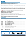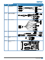
1
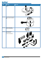
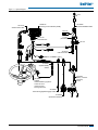
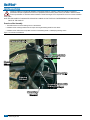
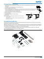
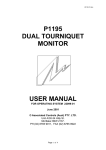
U n i P i l o t®
I n s ta l l at i o n M AN U AL
Assisted Steering Kit Number 91-02400 or 91-02402
Copyrights
© 2013 TeeJet Technologies. All rights reserved. No part of this
document or the computer programs described in it may be
reproduced, copied, photocopied, translated, or reduced in any
form or by any means, electronic or machine readable, recording or
otherwise, without prior written consent from TeeJet Technologies.
Trademarks
Unless otherwise noted, all other brand or product names are
trademarks or registered trademarks of their respective companies or
organizations.
Limitation of Liability
TEEJET TECHNOLOGIES PROVIDES THIS MATERIAL “AS IS”
WITHOUT WARRANTY OF ANY KIND, EITHER EXPRESSED
OR IMPLIED. NO COPYRIGHT LIABILITY OR PATENT IS
ASSUMED. IN NO EVENT SHALL TEEJET TECHNOLOGIES
BE LIABLE FOR ANY LOSS OF BUSINESS, LOSS OF PROFIT,
LOSS OF USE OR DATA, INTERRUPTION OF BUSINESS, OR
FOR INDIRECT, SPECIAL, INCIDENTAL, OR CONSEQUENTIAL
DAMAGES OF ANY KIND, EVEN IF TEEJET TECHNOLOGIES HAS
BEEN ADVISED OF SUCH DAMAGES ARISING FROM TEEJET
TECHNOLOGIES SOFTWARE.
UniPilot®
Table of Contents
PREPARATION2
Components2
Installation6
Overview of the Assembly..............................................................................................................................................................6
Six Simple Steps to Get Going!......................................................................................................................................................................... 7
Assemble Mounting Bracket............................................................................................................................................................................. 7
Configuration Options.............................................................................................................................................................8
UniPilot ESM ........................................................................................................................................................................................................... 9
Assemble UniPilot ESM..................................................................................................................................................................9
Disassemble UniPilot ESM.....................................................................................................................................................9
Secure the Mounting Bracket.........................................................................................................................................................9
Electronics Connections....................................................................................................................................................................................10
Connect SCM Harness.................................................................................................................................................................10
Install the System Ready Switch..................................................................................................................................................10
Connect the Engage/Disengage Switch.......................................................................................................................................10
General Recommended Electronics Installation......................................................................................................................................11
Operation12
Standby Position (Inactive)...........................................................................................................................................................12
Operating Position (Active)...........................................................................................................................................................12
Activate UniPilot ESM...................................................................................................................................................................12
Begin Assisted Steering................................................................................................................................................................12
Deactivate UniPilot ESM.......................................................................................................................................................12
Appendix13
Specifications........................................................................................................................................................................................................13
Operation and Storage Conditions...............................................................................................................................................................14
Trouble Shooting.................................................................................................................................................................................................14
Contact Pressure..................................................................................................................................................................................................14
Replacement of Contact Wheel......................................................................................................................................................................15
98-05226-EN R4
1
UniPilot®
PREPARATION
Before beginning the installation, thoroughly clean the steering wheel and steering column area.
Park the vehicle on a clean, level floor with adequate clearance to work around.
Do not attempt to loosen or attach any fittings while the engine is running.
Photos and illustrations may vary from the actual components provided. This may be due to different installation options, operation modes or
production models.
Always try to use original parts. Built to the highest standards of safety and reliability, TeeJet Technologies parts are to be used for this
system as others might jeopardize the safety and function of the system. TeeJet is not responsible for any redesign or adaptations of the
UniPilot ESM. Any changes to the UniPilot ESM voids the company warranty. TeeJet Technologies supplies a set of mounting brackets that
combined can create a variation of options for your specific vehicle. Not all vehicles have been addressed with these parts and modifications
or additions to these parts may be needed to fit your specific vehicle.
Safety Information
TeeJet Technologies is not responsible for damage or physical harm caused by failure to adhere to the following safety
requirements.
As the operator of the vehicle, you are responsible for its safe operation.
The UniPilot is not designed to replace the vehicle's operator.
Do not leave a vehicle while the UniPilot is engaged.
Be sure that the area around the vehicle is clear of people and obstacles before and during engagement.
The UniPilot is designed to support and improve efficiency while working in the field. The driver has full responsibility for the quality and work
related results.
Disengage and put the UniPilot ESM (Electric Steering Motor) in the standby position before operating on public roads. Put the UniPilot ESM
in the standby position when not in use to prevent accidental engagement or loss of vehicle control.
Components
Unpack the installation kit and identify the required parts for your installation. Soome kits may not include all items listed.
Part Number Description Quantity
32-04040
Switch, Engage/Disengage FieldPilot..............................................................................................................................1
32-04057
Switch, System Ready, UniPilot.......................................................................................................................................1
45-05381
Cable, 3 Pos. Battery 3.66 m w/15 Amp Fuses...............................................................................................................1
45-05626
Cable, Power/CAN/RS232 Adapter to Conxall 8pg.........................................................................................................1
45-07718
Harness, SCM Short........................................................................................................................................................1
45-07727
Cable, SCM to UniPilot Electric Steering Motor (ESM)...................................................................................................1
45-08101
Terminator, CAN Male, WP as Shipped...........................................................................................................................1
78-08075
Steering Control Module (SCM), Pro...............................................................................................................................1
90-02806
Kit, UniPilot Assisted Steering System............................................................................................................................1
28-01029UniPilot Electric Steering Motor (ESM) (included in 90-02806 Kit).................................................................................1
28-01030UniPilot Contact Wheel (included in 90-02806 Kit).........................................................................................................1
91-07015Kit, UniPilot Universal Mounting Bracket (included in 90-02806 Kit)...............................................................................1
90-50013
Kit, Cable Tie Bundle (15)................................................................................................................................................1
98-05284
Manual, Installation, UniPilot...........................................................................................................................................1
Part #
Description
32-04040
Switch, Engage/Disengage
FieldPilot
32-04057
Switch, System Ready,
UniPilot
2
www.teejet.com
Illustration
32-04057
System Ready
Switch
UniPilot®
Part #
Description
45-05381
Cable, 3 Pos. Battery 3.66 m
w/15 Amp Fuses
Illustration
Co
nn
(+ ect
12 o
v) to
45-05381
DC: xx/xx
45-05626
Cable, Power/CAN/RS232
Adapter to Conxall 8pg
POWER IN
Power/DATA
45-05626
CAN
RS-232
45-07718
Harness, SCM Short
GPS Power
CAN
Steering
Wheel Sense
Seat Sensor
SCM Short
Harness
45-07718
DC: xx/xx
Remote
Engage/Disengage
COM Ports
Fault
45-07727
Cable, SCM to UniPilot ESM
Power
SCM Power I/O
45-07727
DC: xx/xx
45-08101
Terminator, CAN Male, WP as
Shipped
78-08075
Steering Control Module
(SCM), Pro
Steering
Actuator
98-05226-EN R4
3
UniPilot®
Part #
Description
90-02806
Kit, UniPilot Assisted Steering
System
28-01029
UniPilot Electric Steering Motor
(ESM) (included in 90-02806
Kit)
28-01030
UniPilot Contact Wheel
(included in 90-02806 Kit)
91-07015
Kit, UniPilot Universal
Mounting Bracket
(included in 90-02806 Kit)
4
www.teejet.com
Illustration
UniPilot®
Figure 1-1: System Diagram
to Matrix Guidance product
8 Pos.
Power/DATA
45-05626
45-05626
Power/CAN/Data Cable
78-08075
Steering Control Module (SCM)
45-07727
SCM Power In/Out
to RS-232
RS-232
POWER IN
CAN
SCM Power I/O
45-07727
DC: xx/xx
TJ CAN
(Terminated)
45-07718
SCM Harness
Power
10A Fuse
GPS Power
CAN
Steering
Actuator
Seat Sensor
Fault
Remote
Engage/Disengage
Steering
Wheel Sense
32-04057
System Ready
Switch
32-04057
System Ready
Switch
45-05381
DC: xx/xx
90-02806
UniPilot
Assisted Steering System
includes 91-07015
UniPilot Universal
Mounting Bracket Kit
Engage / Disengage
32-04020
DC: xx/xx
Com. Ports
45-08101
CAN Terminator
45-05381
Battery 12'/3.6m
w/15Amp
Fuses
Co
nn
(+ ecto
12
v) to
32-04040
Remote Engage/Disengage Switch
32-04020
Optional Footswitch
98-05226-EN R4
5
UniPilot®
Installation
If there are questions concerning the installation of the UniPilot system on a vehicle, or due to the changes in component
specifications the parts supplied in the kit are not as presented in this document, please contact your dealer or TeeJet Customer
service representative for clarification before installation. TeeJet Technologies is not responsible for misuse or incorrect installation
of the system.
NOTE: BE VERY CAREFUL TO ABSOLUTELY SECURE ALL CABLES SO THAT THEY DON’T INTERFERE WITH THE MANY MOVING
PARTS OF THE UNIPILOT!
Overview of the Assembly
• The UniPilot will mount on the steering column of the machine.
• Installation of the mounting bracket does not require removing the steering wheel from the vehicle.
• Installation of the UniPilot does not prohibit movement of the steering wheel or a telescoping steering column.
Figure 1-2: Overview of the Machine
Contact Wheel
UniPilot ESM
System Ready Switch
Mount Location
Steering
Wheel
Connection Cable
Steering
Column
Assembly Base with
Sliding Carriage
Mounting
Bracket
6
www.teejet.com
UniPilot®
Six Simple Steps to Get Going!
1. Assemble Universal Mounting Bracket Kit on steering column so that it can be adjusted with the installation of the
UniPilot ESM.
• See page 8 for recommendations for your specific steering column.
2. Install UniPilot ESM and check spacing.
• Attach the UniPilot ESM to the mounting bracket. The steering wheel should rotate freely around when the UniPilot
ESM is in the Operating Position. When in the Standby Position, there should be 40 mm of space between the
UniPilot contact wheel and the vehicle's steering wheel.
3.
4.
5.
6.
Secure or firmly tighten the mounting parts to Steering Column.
Connect Electronics.
Program Specific Settings on Guidance Console.
Activate & GO!
NOTE: All references to left and right are stated as if the user is seated in
the driver’s seat.
All references to front and back are stated in relationship to the front
and back of the vehicle.
Standby Position
40 mm of space
Operating Position
Assemble Mounting Bracket
The purpose of the mounting bracket is to securely mount the UniPilot ESM (Electric Steering Motor) to the steering column and keep the
UniPilot ESM from rotating around the steering wheel.
Depending on the shape of your steering column, a different mounting bracket configuration may be needed. The following page illustrates a
few examples of installation methods. If you do not see an example that illustrates your vehicle's requirements, please contact your dealer or
TeeJet Customer service representative for clarification on your specific vehicle's installation.
1. Assemble Universal Mounting Bracket Kit on steering column so that it can be adjusted with the installation of the UniPilot ESM.
The mounting bracket will be secured after the UniPilot ESM is assembled.
Figure 1-3: Mounting Bracket Parts
98-05226-EN R4
7
UniPilot®
Configuration Options
Installation Option
Type of Steering
Column
Metal Strap
Round
Use a metal strap to attach
through the appropriate
slots in the mounting
bracket to steering wheel
column and hand tighten
loosely. Multiple slots
have been made available
to accommodate different
steering column sizes.
Square
U-Bolts
Use two (2) u-bolts,
washers and nuts to
attach mounting bracket to
steering wheel column and
hand tighten loosely.
8
www.teejet.com
Round, under
45 cm in diameter
Example
NOTE: The Mounting Bracket does NOT need to point up.
UniPilot®
UniPilot ESM
Assemble UniPilot ESM
1. Slip the sliding carriage onto the assembly base.
2. Slip the steering column bracket between assembly base and sliding carriage.
3. With the UniPilot ESM in the standby position (see page 12), position the
UniPilot ESM a distance of 40 mm from the steering wheel.
4. Tighten the sliding carriage black T-bolt.
Figure 1-4: Insert UniPilot ESM Into Sliding Carriage
Sliding
Carriage
Figure 1-8: Positioning of UniPilot ESM
1.6"
40 mm
9.25"
235 mm
Assembly
Base
Figure 1-5: Slip UniPilot ESM Onto Mounting Bracket
Steering
Column
Bracket
Sliding
Carriage
Figure 1-9: Positioning of UniPilot ESM
Figure 1-6: Tighten Sliding Carriage
T-Bolt
Disassemble UniPilot ESM
The disassembly of the steering motor UniPilot ESM happens in the reverse order of
the assembly.
Figure 1-7: Secure the Mounting Bracket
Secure the Mounting Bracket
Firmly tighten u-bolts, metal strap or other attachment device to the steering column
to make sure that bracket(s) does not move when the steering wheel is rotated.
Make sure steering wheel freely rotates when the UniPilot ESM is in the operating
position (see page 12).
HINT: Mark the ideal position of the UniPilot ESM on the steering wheel bracket to
make the next vehicle change easier.
98-05226-EN R4
9
UniPilot®
Electronics Connections
Connect SCM Harness
Connect UniPilot ESM to the Steering Control Module (SCM) through the SCM harness using the Steering Actuator connection.
Figure 1-10: Electronics Connection
45-07727
SCM Power In/Out
SCM Power I/O
45-07727
DC: xx/xx
Steering
Actuator
Power
90-02806
UniPilot
Assisted Steering System
78-08075
Steering Control Module (SCM)
Install the System Ready Switch
1. Using a 3 mm allen wrench, remove the existing screw on either the top Figure 1-11: System Ready Switch Assembly
right or top left side of the UniPilot ESM.
2. Use the existing screw to mount the switch bracket using the small hole
on the bracket.
3. Disassemble top nut and washer from System Ready Switch.
4. Slide detector button through large hole in bracket.
5. Hand tighten the washer and nut back on to the detector.
Figure 1-13: System Ready Switch
Figure 1-12: System Ready Switch Detail
Nut
Washer
Bracket
Nut
Connect the Engage/Disengage Switch
Connect the Engage/Disengage Switch to the connector on the SCM
harness labeled Remote Engage/Disengage. Install the push button in
a location that is easily accessible during operation of the machine. This
switch is not required if the optional foot switch 32-04020 is used.
10
www.teejet.com
UniPilot®
General Recommended Electronics Installation
The Steering Control Module (SCM) must be mounted securely flat to the floor of the cab with the arrow facing forward. The control console
can be mounted to the operator’s preference. The GPS antenna should be mounted as far forward as possible on top of the cab or hood
(depending on vehicle) on a metal surface of at least 10 cm square.
Figure 1-14: Recommended Electronics Installation
SCM
Console
GPS
98-05226-EN R4
11
UniPilot®
Operation
If there are questions concerning the operation of the UniPilot system on this vehicle, or due to the changes in component specifications the
parts supplied in the kit are not exactly as presented in this document, please contact your dealer or TeeJet Customer service representative
for clarification before operation. TeeJet Technologies is not responsible for misuse or incorrect operation of the system.
NOTE: BE VERY CAREFUL TO ABSOLUTELY SECURE ALL CABLES SO THAT THEY DON’T INTERFERE WITH THE MANY MOVING
PARTS OF THE UNIPILOT!
WARNING! D
isengage and put the UniPilot ESM in the standby position
before operating on public roads.
Standby Position (Inactive)
Figure 1-15: UniPilot ESM in Standby Position
To put the UniPilot ESM in the standby position, pull the contact wheel away from the
steering wheel until the standby mechanism engages and the UniPilot ESM is not
pulled in the direction to the steering wheel anymore.
Operating Position (Active)
To bring the UniPilot ESM into its operating position, pull/push the contact wheel away
from the steering wheel until the standby mechanism disengages and the UniPilot
ESM is pulled in the direction to the steering wheel again. The UniPilot ESM is active
and ready for action now.
Figure 1-16: Pull UniPilot ESM to Operation Position
Activate UniPilot ESM
With each power cycle of the guidance console, the UniPilot ESM will need to be activated.
Figure 1-17: System Ready Switch
1. Make sure the guidance console is on and has completed the start-up process.
2. Press the System Ready Switch 3 to 4 times to acknowledge the UniPilot ESM is
in the operating position and ready.
Begin Assisted Steering
To begin using the UniPilot to assist with steering:
1. Make sure the UniPilot ESM is in the operating position.
2. While the vehicle is moving in a forward motion, press the Remote Engage/
Disengage Switch or Footswitch.
NOTE: A guidance line must be established before the UniPilot can begin assist
steering.
Deactivate UniPilot ESM
1. Press the remote Engage/Disengage Switch or Footswitch.
12
www.teejet.com
UniPilot®
Appendix
Specifications
Connections
RS232
9 position (Male)
Length
Environmental
1+2
Motor A
Storage temperature
-40°C to 90°C
3+4
Motor B
Operation temperature
-40°C to 80°C
5
n.c.
Protection rating
IP 30
6
Encoder + 10V
Chemical contamination
Water and aqueous saline solution
7
Encoder GND
Dilute acids and bases,
8
Encoder Channel A
Aliphatic hydrocarbons
9
Encoder Channel B
Herbal and animal fats and oils
0.5 m
Ethanol
Diesel
Motor
Nominal Voltage
12 V
Nominal Torque
0.5 Nm
Nominal Speed
390 rpm
Nominal Current
2A
Maximal Current
4.5 A
Starting Torque
2 Nm
Encoder
Supply voltage
4.5 V– 26.5 V
Impulses
16 Imp / rev (open collector)
Perspiration
Inflammability
Housing of low flammability according
to UL 94 HB at d = 1,6 mm
Mechanical resistance
Rough handling on construction site
(e.g. mortar, cement, lime, resistant
against scratches and abrasion)
Drop
0.3 m to all surfaces
0.7 m to rubber mat in vehicle cabin
Values are subject to change without prior notice.
Dimensions / Mechanical
Height
215 mm (260 mm)
(with mounting bracket)
Width
90 mm
Depth
115 mm (145 mm)
(with mounting bracket)
Weight
2900 g
98-05226-EN R4
13
UniPilot®
Operation and Storage Conditions
Electronic components of the UniPilot ESM are designed for rough environmental conditions like agricultural applications. However it should
always be installed in the operator's station of the vehicle.
Warning! Never use a pressure washer to clean the UniPilot ESM. If needed wipe with a moist cloth.
Warning! Always protect the UniPilot ESM from falling onto a hard surface, to prevent internal damage.
Life expectance of the UniPilot ESM can be extended by storing it under optimal conditions. Keep all mounting screws and brackets together
if the motor is not installed in a stored vehicle. Avoid locations with high humidity as well as high temperatures near generators, radiators or
near windows in direct sunlight.
Trouble Shooting
Description
Cause
Troubleshooting
UniPilot ESM does
not turn
No signals from SCM (steering unit) to UniPilot ESM
Check steering system
Open wire between steering system and UniPilot ESM
Check cable between steering system and UniPilot ESM
Open wire between power supply and UniPilot ESM,
UniPilot ESM is not supplied with voltage
Check power supply of UniPilot ESM
Contact wheel of
UniPilot ESM slips
on steering wheel
Spring force of collapsible mechanism of UniPilot ESM Check distance from contact wheel and stand by position.
is too low
Once verified then adjust contact pressure as stated below.
Increase spring force of collapsible mechanism of UniPilot
ESM (see page 35 for details)
Contact wheel of UniPilot ESM is worn
Replace contact wheel of UniPilot ESM (see page 36 for
details)
Contact Pressure
Should the contact wheel slip while activating the steering wheel, the contact pressure needs to be increased. Either slide the UniPilot ESM
towards the steering wheel or increase the spring preload.
To Increase / Decrease the Spring Preload:
1. Disassemble the UniPilot ESM.
2. Bring the motor to the normal operating position, so that the spring tension against the two mounting screws is at it’s lowest.
3. Loosen the two mounting screws in the assembly base with a 2.5 mm allen wrench, if necessary hold the inside nut with a 8mm open end
wrench.
4. To increase pressure move the two mounting screws with the spring ends in direction (1) To reduce pressure move the two mounting
screws with the spring ends in direction (2).
5. Once you have the desired spring pressure tighten the two mounting screws.
6. Reassemble the UniPilot ESM to its mounting bracket on the steering column.
Figure 1-18: Loosen Mounting Bracket Screws
14
www.teejet.com
Figure 1-19: Increase/Decrease Spring Preload
UniPilot®
Replacement of Contact Wheel
The contact wheel is a wear part and has to be replaced when worn.
Figure 1-20: Unscrew Cover
To replace the contact wheel:
1.
2.
3.
4.
5.
6.
Put the UniPilot ESM in the standby position.
Unscrew the cover mounting screw with a 3 mm allen wrench.
Remove the cover from the contact wheel.
Pull the wheel from the 4 holding pins.
Slip the new contact wheel onto the four holding bolts and press it down.
Replace the cover and hand tighten the holding screw.
Figure 1-21: Remove Top Cover
Figure 1-22: Contact Wheel With Holding Pins
98-05226-EN R4
15
®
U
n
i
P
i
l
o
t
I n s ta l l at i o n M a n ua l
Six Simple Steps to Get Going!
1. Assemble Universal Mounting Bracket Kit on steering column so that it can be
adjusted with the installation of the UniPilot ESM.
2. Install UniPilot ESM and check spacing.
• Attach the UniPilot ESM to the mounting bracket. The steering wheel should
rotate freely around when the UniPilot ESM is in the Operating Position. When
in the Standby Position, there should be 40 mm of space between the UniPilot
contact wheel and the vehicle's steering wheel.
3.
4.
5.
6.
Secure or firmly tighten the mounting parts to Steering Column.
Connect Electronics.
Program Specific Settings on Guidance Console.
Activate & GO!
Standby Position
40 mm of space
Mølhavevej 2
9440 Aabybro
Denmark
Tel: +45 9696 2500 • Fax: +45 9696 2501
www.teejet.com
98-05226-EN R4 English/International
© TeeJet Technologies 2013
Operating Position