1
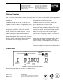
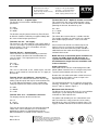
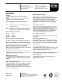
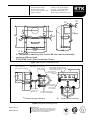
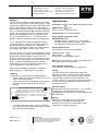
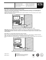
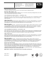
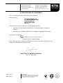
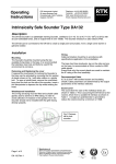
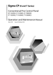
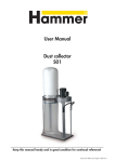
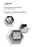
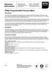
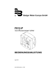
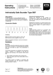
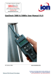
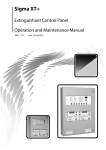
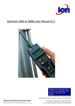
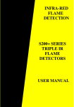
Operating Instructions RTK Instruments Limited St James Business Park, Knaresborough, North Yorkshire, England. HG5 8PJ Telephone: +44 (0)1423 580500 Facsimile: +44 (0)1423 580501 Web: www.rtkinstruments.com Email: enquiry@ rtkinstruments.com DA135 Intrinsically Safe LED Beacon Introduction This manual provides the information necessary to install, connect, test and maintain RTK’s intrinsically safe LED Beacon. Description The DA135 range of LED Beacons provide powerful visual alarm signals in safe and hazardous areas. The DA135 not only performs all the functions of the earlier DA134 xenon beacon, but allows the user to connect a sounder and a pushbutton, to make a full alarm annunciator. There are two models available; the standard unit which has a variable flash type, this can flash in three different flash patterns, single flash, double flash or triple flash and also a dual colour version that can single flash with a different colour depending on the input. The single colour version is available in five super-bright colours – red, green, amber, blue and white. The dual colour version can come in a combination of any two colours. The DA135 can be operated alone or in conjunction with an intrinsically safe Sounder and pushbutton to create a single point annunciator. The user can also configure the beacon using a DIL switch for: • Lock-in or no lock-in input • Auto or Manual reset When installed with a Sounder it is possible to add the extra silence function by the addition of a pushbutton. This will silence the sounder until the signal is cleared, or for a set time between 1 – 60 minutes, selectable by the user. These units can be used in gas group IIC, IIB or IIA powered through a 28V Zener Barrier or an Isolating Interface unit. An internal current limiting device, combined with the exceptionally high efficiency of LED’s, enables both beacon and sounder to be driven through a single barrier/isolator in IIC areas with consequent savings in hardware and plant cabling costs. Page 1 of 13 DA135 Rev 4 Manufacturers of Alarm Annunciators and Systems | Sequential Event Recorders | Display Facias Hazardous Area Interface, Alarm and Display Products | Signal Conditioning & Trip Amplifiers | Process Instrumentation ISO 9001 FM 14290 RTK Instruments Limited St James Business Park, Knaresborough, North Yorkshire, England. HG5 8PJ Telephone: +44 (0)1423 580500 Facsimile: +44 (0)1423 580501 Web: www.rtkinstruments.com Email: enquiry@ rtkinstruments.com Different Versions Standard Version DA135-XX Note: The colour of the unit will be added to the product name in the following format, DA135-xx. I.e. DA135-RD would be red. Dual Colour Version DA135-XX-YY Note: The colour of the unit will be added to the product name in the following format, DA135-XX-YY. I.e. DA135-RD-GN would be red and green. The DA135 provides the user with a choice of three flash patterns (single, double or triple bursts). The repetition rate for these bursts are approximately every one second. The DA135 provides the user with a choice of two colours at one flash rate. The repetition rate for this flash is approximately every one second. Flashing of a particular colour is triggered by a voltage being applied to the control input terminals. This can be achieved through separate power signals to either terminals SK7 & SK8, terminals SK9 & SK10 or to both. It can also take power from terminals SK5 & SK6 to give an input from its own IS power supply to either or both the control inputs. Control input 1 (terminals SK7 & SK8) triggers colour 1, control input 2 (terminals SK9 & SK10) triggers colour 2. A flash pattern is triggered by a voltage being applied to the control input terminals. This can be achieved through separate power signals to either terminals SK7 & SK8, terminals SK9 & SK10 or to both. It can also take power from terminals SK5 & SK6 to give an input from its own IS power supply to either or both the control inputs. These inputs only draw a small amount of power to trigger the input. Control input 1 (terminals SK7 & SK8) triggers a single flash, control input 2 (terminals SK9 & SK10) triggers a double flash, input on both at the same time triggers a triple flash. On the dual colour version colour 2 has a higher priority, so the beacon will flash colour 2 until the alarm has cleared even if colour 1 is in alarm. In this case colour 1 can only be acknowledged and reset when it is visible. The two control signals are isolated from each other and from the power input, allowing connection to other IS circuits without the need for system certificates. Connections SW1 (NO LOCK-IN) + HAZ AREA SUPPLY VIA SAFETY BARRIER 3 4 2 ARES(AUTO RESET) 5 6 7 8 VR1 DISABLE 1 LOCK-IN (MANUAL RESET) 1 2 RE-ALARM 9 10 +2 +1 + + SAFE 3 FLASH AREA CONTROL FLASH SUPPLY PWR O/P CONTROL 12-26V INPUT ENABLE 11 12 RE-ALARM LK2 TIMER ADJ 1-60 MINS 13 14 + ACK P/B + SOUNDER OUTPUT Figure 1: Location of terminals and controls General General connection details for all models are shown in Figure 1. Page 2 of 13 DA135 Rev 4 Manufacturers of Alarm Annunciators and Systems | Sequential Event Recorders | Display Facias | Hazardous Area Interface, Alarm and Display Products | Signal Conditioning & Trip Amplifiers | Process Instrumentation ISO 9001 FM 14290 RTK Instruments Limited St James Business Park, Knaresborough, North Yorkshire, England. HG5 8PJ Terminal SK1 & 2 – IS power input. The interface must match the following input parameters: Ui = 28V Ii = 110mA Pi = 0.8W Telephone: +44 (0)1423 580500 Facsimile: +44 (0)1423 580501 Web: www.rtkinstruments.com Email: enquiry@ rtkinstruments.com Terminal SK13 & 14 – Optional sounder connection. This terminal has the same maximum power safety parameters as the Zener Barrier or Galvanic Isolator powering the beacon, therefore they are: Uo = 28V Io = 110mA Po = 0.8W The beacons may be powered from any Zener Barrier or Galvanic Isolator certified by an approved body with the same or lower output parameters. Terminals SK3 & 4 – 24V supply. This interface is for connection to a 24V supply within a safe area, this input is specially designed to protect the internal circuitry. For use in a hazardous area this terminal will not be used. Terminal SK5 & 6 – Control power These terminals are connected directly to terminals 1 & 2 to allow the beacon to be controlled from the same IS supply. The output parameters for these terminals are: Uo = 28V Io = 110mA Po = 0.8W This can be connected to the control inputs, but will draw a small amount of current from the IS supply to the Beacon. Terminal SK7 & 8 and SK9 &10 – Control input These inputs are isolated and certified as non-energy storing (Ceq=0,Leq=0) and may be connected into any IS system without affecting the safety, provided the safety input parameters of the unit are not exceeded. Ui = 40V Ii = 450mA Pi = 1.3W Terminal SK11 & 12 – Pushbutton connection The output parameter for this terminal are: This allows direct connection to a suitable sounder. The sounder should be an intrinsically safe sounder, with suitable input parameters, such as the RTK DA132. If the beacon and sounder are mounted apart, for intrinsic safety assessment the capacitance and inductance of the interconnecting cable should be added to that of the cable connecting the barrier or Isolator to the beacon. NOTE: Because of the limited power available in IS circuits, the LED’s flash rate will decrease on systems with a Sounder connected. Because of this limitation the single flash rate should be used in these situations. Cable connections Connections to the unit are made through four cable glands (20mm Isometric fine or 13.5Pg threads) into a separate terminal board at the base of the unit. Remove the unit cable termination section front cover by releasing the two captive screws to expose the terminals for wiring up the unit. The terminal board consists of 7 two-way rising clamp terminals, numbered 1 – 14, capable of accepting up to 2 2.5mm cable as shown in Figure 1. Maximum Cable Parameters The DA135 can be connected to any IS system without affecting the system Group Classification or any insulation or cable requirements. The power and control inputs are isolated from each other, therefore the safety parameters of the cables depend on the source of supply or control signal. The supply is 24VDC nominal via an IS barrier or interface. Uo = Ui Io = 6mA Po = 40mW They may be connected to any mechanically operated switch in the same hazardous area as the beacon providing the switch has IP20 Protection and can withstand 500Vrms insulation test to earth for 1 minute. Page 3 of 13 DA135 Rev 4 Manufacturers of Alarm Annunciators and Systems | Sequential Event Recorders | Display Facias | Hazardous Area Interface, Alarm and Display Products | Signal Conditioning & Trip Amplifiers | Process Instrumentation ISO 9001 FM 14290 RTK Instruments Limited St James Business Park, Knaresborough, North Yorkshire, England. HG5 8PJ Telephone: +44 (0)1423 580500 Facsimile: +44 (0)1423 580501 Web: www.rtkinstruments.com Email: enquiry@ rtkinstruments.com Installation Location The DA135 LED beacon has been certified to: II 1G EEx ia IIC T6. When connected to an approved system it may be installed in: Zone 0 Explosive gas air mixture continuously present. Zone 1 Explosive gas air mixture likely to occur, in normal operation. Horizontal pipe mounting Attach the instrument mounting bracket to the horizontal pipe or post (diameter 40 to 80mm) with the pipe mounting U-bolt and two M8 nuts and washers. Fix the beacon casing to the instrument mounting bracket by the two M8x16mm screws and washers and the blind insert threads in the back of the indicator casing. Be used with gases in groups: Vertical pipe mounting Attach the instrument mounting bracket to the vertical pipe or post (diameter 40 to 80mm), with the pipe mounting U-bolt and two M8 nuts and washers. Then, through the casing slots, attach the casing to the instrument mounting bracket by the two M8x25mm screws and remaining two nuts and washers Group A Group B Group C Direct surface mounting See Figure 2 for relevant dimensions. Three methods are possible: Zone 2 Explosive gas air mixture not likely to occur, and if it does, it will only exist for a short time. Propane Ethylene Hydrogen Having a Temperature Classification of: T6- 85°C, so can be used in all temperature classes. Operational Conditions and Power Requirements For installations in IIC hazardous areas, power for the beacon is provided from the safe area through intrinsically safe interface units (eg, S951 and WIS1211) from a nominal 24VDC supply. See table A for recommended interfaces. The DA135 can also be used in a safe area from a 24V supply connected to terminals SK3 & SK4. Or a 12V supply through terminals SK1 & SK2. Mounting the beacons The beacons can be installed directly in any zone by surface mounting or by pipe/post mounting using the PIP68 kit. Panel mounting with back access Either by two M8 stainless steel screws into the blind insert threads (10mm deep) in the back of the beacon or by two M6 pan head or M8 hexagon head stainless steel screws, washers and nuts through the mounting slots in the case. Panel mounting with no back access By two M6 pan head x14mm (minimum) stainless steel screws, washers into tapped holes in the panel plate through the mounting slots in the case. Wall mounting by two No.10 pan head x30mm stainless steel self-tapping or wood screws and M6 washers using casting slot. Note: Mounting screws nuts and washers are not supplied with the beacon. Pipe and post mounting Figure 3 Illustrates the technique for pipe/post mounting using the PIP68 Kit. The kit consists of an instrument mounting bracket, a pipe-mounting U bolt, four M8 fixing screws (two of 16mm length for horizontal mounting and two of 25mm length for vertical mounting) and four nuts and washers. Page 4 of 13 DA135 Rev 4 Manufacturers of Alarm Annunciators and Systems | Sequential Event Recorders | Display Facias | Hazardous Area Interface, Alarm and Display Products | Signal Conditioning & Trip Amplifiers | Process Instrumentation ISO 9001 FM 14290 RTK Instruments Limited St James Business Park, Knaresborough, North Yorkshire, England. HG5 8PJ Telephone: +44 (0)1423 580500 Facsimile: +44 (0)1423 580501 Web: www.rtkinstruments.com Email: enquiry@ rtkinstruments.com 10 10 B 110crs 110crs 48 157 A 8.2 A 13.2 B 65.5 96 125crs 148 11.5 A: Two position mounting slots to take M8 Hex head restrained by casting or M6 pan head B: Blind M8 Insert (Max Penetration 15mm) Figure 2 Direct Surface mounting (in mm) M8 x 16 stainless steel screw and washer M8 stainless nut + washer M8 stainless steel U-bolt Holes: four off Pg 13.5mm or 20mm ISOmetric fine thread cable glands, minimum 10mm thread length required Hex head held against flats in case moulding 96 72.0 89.5 76 Nylon coated stainless steel pipe clamp M8 x 25 hex. head stainless steel screw + nut + washer For mounting on pipes from 40 to 80mm O/D a) Horizontal pipe mounting b) Vertical pipe mounting Figure 3 Pipe/post mounting (in mm) Page 5 of 13 DA135 Rev 4 Manufacturers of Alarm Annunciators and Systems | Sequential Event Recorders | Display Facias | Hazardous Area Interface, Alarm and Display Products | Signal Conditioning & Trip Amplifiers | Process Instrumentation ISO 9001 FM 14290 RTK Instruments Limited St James Business Park, Knaresborough, North Yorkshire, England. HG5 8PJ Glanding The unit cable termination section contains four gland holes in the casing fitted with four blanking plugs. After removal of the blanking plug or plugs cable glands may be passed through these holes onto a tapped metal plate inside the cable termination. The plate will directly accept 15.3Pg DIN 40430 or M20 Isometric fine thread glands. At least 10mm of thread is needed to engage into the plate (Allowing for 5mm case wall thickness plus 3.175mm plate thickness). The internal plate provides electrical continuity between all cable glands. Users should provide suitably rated glands to either specification above. Longer thread length glands will be required if a backing or lock nut is considered necessary. To maintain IP rating we recommend that metal glands with rubber O-ring seals be used. The case itself has a clearance hole of 20.5mm and the internal plate may be removed thus allowing other types of gland to be fitted provided the case itself is not affected. If the internal plate is removed, lock nuts will be required for each gland and any remaining blanking plugs. If electrical continuity between the glands is required then it must be established by other means e.g. A tagged washer under the lock nut. All unused holes must be blanked off. Threaded blanking plugs are supplied fitted in 4 positions. Labelling The beacons are shipped with the following labels:• A label showing the connection details on the inside of the terminal housing lid • A label marking with the appropriate Serial No.and manufacturing date again inside the terminal housing. LED BEACON TYPE: DA135-XX-YY EEx ia IIC T6 Tamb=55°C CERT No.Baseefa03ATEX0669 TERMINAL SK1&2&14 - Ui = 28V, Ii = 110mA, Pi = 0.8W TERMINALS SK3&4, SK5&6&13 - Uo = Ui, Io = Ii, Po = Pi (SK1&2) TERMINALS SK7&8, 9&10 - Ui = 40V, Ii = 450mA, Pi = 1.3W TERMINALS SK11&12 - Uo = Ui(SK1&2), Io = 6mA, Po = 40mW KNARESBOROUGH UK INSTRUMENTS HG5 8PJ II 1 G 1180 Figure 4: Certification label. • The certification label (Figure 4) on the top of the unit shows all relevant safety information, and code letters indicating LED colour(s). Page 6 of 13 DA135 Rev 4 Telephone: +44 (0)1423 580500 Facsimile: +44 (0)1423 580501 Web: www.rtkinstruments.com Email: enquiry@ rtkinstruments.com Specification Standards: CENELEC BS EN50014 & 50020 & 50284 Approved for : II 1G o o EEx ia IIC T6 (Ta -20 C to +55 C) Certificate No : Baseefa03ATEX0669 Power supply requirements (Vin) Hazardous area use All models (with a zener barrier ) : 24 to 28VDc All models (with a galvanic isolator) : 20 to 28VDC See table A for recommended IS Interfaces. Current Requirements Typical when set to triple flash @24VDC Without Sounder 20mA With Sounder 45mA Steady State (Acknowledged): 45mA Note: Current requirement is reduced for double flash and further reduced for single flash. Selectable Re-alarm delay User selectable re-alarm delay of 1-60 minutes. Fusing The Terminal board is fitted with two component approved fused, these protect the internal electronics from damage if the unit is incorrectly connected and also protect the output circuit to the Sounder. For safety reasons these must not be replaced but instead the whole unit or terminal board returned to RTK for repair/replacement. Electrical Safety Will not store or generate more than 1.5V, 0.1A, 20µJ or 25mW when connected to intrinsically safe equipment with a maximum open circuit voltage of not more than 28V. Casing GRP (glass reinforced plastic) casing to IP65. Translucent acrylic dome for LED housing. Good resistance to hostile environments, saline atmospheres and impact damage. Manufacturers of Alarm Annunciators and Systems | Sequential Event Recorders | Display Facias | Hazardous Area Interface, Alarm and Display Products | Signal Conditioning & Trip Amplifiers | Process Instrumentation ISO 9001 FM 14290 RTK Instruments Limited St James Business Park, Knaresborough, North Yorkshire, England. HG5 8PJ Cable Entry Four clearance holes for glands, internal plate tapped to accept 13.5Pg DIN40330 or M20 Isometric fine thread cable glands; shipped with blanking plugs. Telephone: +44 (0)1423 580500 Facsimile: +44 (0)1423 580501 Web: www.rtkinstruments.com Email: enquiry@ rtkinstruments.com EMC Compliance Immunity to EN61000-6-2 : 2001 Emissions to EN6100-6-4 : 2001 Ambient Temperature Operating: -20°C to +55°C Storage: -20°C to +80°C Mounting Direct mounting to walls or flat surfaces. Or pipe/post mounting using PIP68 kit. Humidity 0-95% RH, non condensing Connections 2 Rising clamp screw terminals for cables up to 2.5mm . Safe area use Direct connection : 24VDC to terminals SK3 & SK4 : 12VDC to terminals SK1 & SK2 Protection IP65 Operating Instructions Single Colour Version Only Control input 1 is present the beacon will have a single flash. If only control input 2 is present the beacon will have a double flash. If both inputs are present the beacon will have a triple flash. Dual Colour Version When Only Control input 1 is present the beacon will flash colour 1. If only control input 2 is present the beacon will flash colour 2. If both inputs are present the beacon will flash colour 2 as this is the higher priority alarm. If control input 2 then clears the beacon will flash colour 1 again until this also clears. Stand Alone operation controlled from other IS systems Figure 6, shows the beacon in a stand-alone system with the flash control supplied from other IS systems. SAFE AREA HAZARDOUS AREA 1-2 + 3-4 - 5-6 7-8 + 9-10 11-12 13-14 + 12-40V FROM AN IS SYSTEM + BARRIER OR IS INTERFACE UNIT +24V DC SUPPLY Figure 6 stand alone system controlled from other IS systems Page 7 of 13 DA135 Rev 4 Manufacturers of Alarm Annunciators and Systems | Sequential Event Recorders | Display Facias | Hazardous Area Interface, Alarm and Display Products | Signal Conditioning & Trip Amplifiers | Process Instrumentation ISO 9001 FM 14290 RTK Instruments Limited St James Business Park, Knaresborough, North Yorkshire, England. HG5 8PJ Telephone: +44 (0)1423 580500 Facsimile: +44 (0)1423 580501 Web: www.rtkinstruments.com Email: enquiry@ rtkinstruments.com Stand Alone operation with internal control power Figure 7, shows the beacon in a stand-alone system. It shows the beacon powered from a suitable IS interface from a 24V supply. Both control signals are controlled directly from the unit with control from a switch operated in the hazardous area. SAFE AREA HAZARDOUS AREA 1-2 + 3-4 - 5-6 + 7-8 + 9-10 11-12 13-14 + CONTROL SWITCH + BARRIER OR IS INTERFACE UNIT +24V DC SUPPLY Figure 7 stand alone system controlled from own IS supply NOTE: It is possible to have one control signal controlled directly from the unit with the other input coming from other IS systems. Page 8 of 13 DA135 Rev 4 Manufacturers of Alarm Annunciators and Systems | Sequential Event Recorders | Display Facias | Hazardous Area Interface, Alarm and Display Products | Signal Conditioning & Trip Amplifiers | Process Instrumentation ISO 9001 FM 14290 RTK Instruments Limited St James Business Park, Knaresborough, North Yorkshire, England. HG5 8PJ Telephone: +44 (0)1423 580500 Facsimile: +44 (0)1423 580501 Web: www.rtkinstruments.com Email: enquiry@ rtkinstruments.com DA135 Beacon Single point Annunciator with sounder Figure 8, shows the beacon connected to a sounder from terminal SK13 & SK14. It is also connected to a pushbutton. The beacon is powered from a suitable IS interface from a 24V supply. The control signals are controlled directly from another IS systems. When an alarm occurs the beacon will flash and the sounder activated. An alarm occurring is when a input is triggered on control input 1 or 2. SAFE AREA HAZARDOUS AREA 1-2 + 3-4 5-6 7-8 + - + 9-10 11-12 13-14 + + + 12-40V FROM AN IS SYSTEM ACK/RESET + BARRIER OR IS INTERFACE UNIT +24V DC SUPPLY Figure 8 DA135 connected as single point annunciator with sounder. NOTE: Because of the limited power available in IS circuits, the LED’s flash rate will decrease on systems with a Sounder connected. Because of this limitation the single flash rate should be used in these situations DA135 Beacon as Single point Annunciator without sounder Figure 9, shows the beacon connected to a pushbutton. The beacon is powered from a suitable IS interface from a 24V supply. The control signals are controlled directly from another IS systems. When an alarm occurs the beacon will flash. An alarm occurring is when an input is triggered on control input 1 or 2. SAFE AREA HAZARDOUS AREA 1-2 + 3-4 - 5-6 7-8 + 9-10 11-12 13-14 + + 12-40V FROM AN I/S SYSTEM ACK/RESET + BARRIER OR I/S INTERFACE UNIT +24V DC SUPPLY Figure 9 DA135 connected as single point annunciator without sounder Page 9 of 13 DA135 Rev 4 Manufacturers of Alarm Annunciators and Systems | Sequential Event Recorders | Display Facias | Hazardous Area Interface, Alarm and Display Products | Signal Conditioning & Trip Amplifiers | Process Instrumentation ISO 9001 FM 14290 RTK Instruments Limited St James Business Park, Knaresborough, North Yorkshire, England. HG5 8PJ Telephone: +44 (0)1423 580500 Facsimile: +44 (0)1423 580501 Web: www.rtkinstruments.com Email: enquiry@ rtkinstruments.com Single point Annunciator setup The simple single point annunciator, can be set up to operate with the following functions: No Lock-in (SW1, Position 1 - off) Alarms will reset immediately when the contacts clear (i.e. the alarm is not latched), although whilst in the alarm state the Acknowledge function operates normally. Lock-in with Auto reset (SW1, Position 1 - on, Position 2 - on) Alarms will lock-in when either control input 1 or 2 is triggered. When the alarm state is acknowledged, using the pushbutton, the LED goes steady. After acknowledge the LED will automatically reset as soon as the input returns to normal. Single colour version In lock-in mode if the input changes from a single to a double or vice versa this it not considered as a new alarm, but the flash rate will change depending on which input is present. The first input is locked in until the alarm is acknowledged, the alarm can only clear when both inputs have returned to normal. Dual colour version If input 2 is triggered while input 1 is locked in the beacon will flash colour 2 until the contact on input 2 is cleared and acknowledged. It will then return back to the state of colour 1. While input 2 is present input 1 cannot be acknowledged until input 2 has been cleared and acknowledged. If input 2 is present, and input 1 is detected, then this will lock-in but will not flash colour 1 until input 2 has cleared and acknowledged. Lock-in with Manual reset (Position 1 - on, Position 2 - off) Alarms will lock-in when either control input 1 or 2 is triggered. When the alarm state is acknowledged, the LED goes steady. When the input returns to normal the unit will stay in the acknowledged state until the pushbutton is pressed again to reset the alarm. The alarm can only be reset if the inputs have cleared. Single colour version In lock-in mode if the input changes from a single to a double or vice versa this it not considered as a new alarm, but the flash rate will change depending on which input is present. The first input is locked in until the alarm is acknowledged, the alarm can only clear when both inputs have returned to normal. Dual colour version If input 2 is triggered while input 1 is locked in the beacon will flash colour 2 until the contact on input 2 is acknowledged and rest. It will then return back to the state of colour 1. While input 2 is present input 1 cannot be acknowledged or reset until input 2 has been acknowledged and reset. If input 2 is present, and input 1 is detected, then this will lock-in but will not flash colour 1 until input 2 has been acknowledged and reset. Re-alarm (LK2 in EN Position) When the alarm state is acknowledged, the sounder is silenced (if connected) and the LED’s goes steady. If the alarm is still present after a programmable time delay then the alarm will re-activate. In manual reset mode if the alarm has cleared the timer will reset and the alarm will need to cleared by a reset. If the input returns before a reset the timer will start running again. The re-alarm time is user selectable between 1 and 60 minutes by rotating VR1 clockwise to increase the time and anti-clockwise to decrease the time. This re-alarm function can be disabled by moving LK2 into the disable position (DE). NOTE: When a Sounder is connected the flash rate of the LED’s will decrease. Page 10 of 13 DA135 Rev 4 Manufacturers of Alarm Annunciators and Systems | Sequential Event Recorders | Display Facias | Hazardous Area Interface, Alarm and Display Products | Signal Conditioning & Trip Amplifiers | Process Instrumentation ISO 9001 FM 14290 RTK Instruments Limited St James Business Park, Knaresborough, North Yorkshire, England. HG5 8PJ Testing Telephone: +44 (0)1423 580500 Facsimile: +44 (0)1423 580501 Web: www.rtkinstruments.com Email: enquiry@ rtkinstruments.com Recommended IS Interfaces Warning For intrinsically safe applications, make sure all testing is carried out according to the appropriate nationally accepted code of practice. If fault finding is necessary, make sure permission to carry out the work is granted and/or conform to required company procedures to avoid the possibilities of causing a plant malfunction. In safe areas or workshops the voltage applied should be between 12 and 28V dc between terminals SK3 & SK4. NOTE: Connecting 24V DC directly to terminals 1 & 2 may damage the unit. To test correct flash pattern/ colour occurs, take power from terminals SK5 & 6 and connect to terminals SK7 & 8 or SK9 & 10. Location Zone 1, IIC Supply 20V – 28VDC Recommended Interface Units Zener Barriers: MTL7728+, MTL7778AC Galvanic Isolators: MTL5025 Table A: Recommended IS interface Note: Any IS interface with suitable output parameters may be used, but for best performance interfaces in Table A are recommended (or equivalents). Please contact RTK for recommended competitor IS interfaces Maintenance Routine Maintenance The only maintenance required is limited to routine periodic inspection and cleaning. At monthly intervals (or whenever necessary) Clean the flash dome with a dry non-abrasive cloth. Do not use abrasive substances to clean the lens. At six-monthly intervals Check that the mechanical mounting of the beacon is secure. Remove terminal cover and check for condensation or corrosion especially on the terminals. Faulty Units Apart from the test operations and the maintenance procedures described above, no other repair work can be carried out by the user, as there are no replaceable parts in the beacon. Faulty units should be returned to RTK for investigation and possible replacement. Page 11 of 13 DA135 Rev 4 Manufacturers of Alarm Annunciators and Systems | Sequential Event Recorders | Display Facias | Hazardous Area Interface, Alarm and Display Products | Signal Conditioning & Trip Amplifiers | Process Instrumentation ISO 9001 FM 14290 RTK Instruments Limited St James Business Park, Knaresborough, North Yorkshire, England. HG5 8PJ Telephone: +44 (0)1423 580500 Facsimile: +44 (0)1423 580501 Web: www.rtkinstruments.com Email: enquiry@ rtkinstruments.com Other RTK Products RTK Instruments produce a range of complementary products for many applications in the Industrial Control and Instrumentation field for both safe and hazardous areas, as listed below. All standard products come with a 5 year warranty from this ISO9001:2000 approved company: Alarm Annunciators Rack Mounted Alarm Systems Sequence of Event Recorders Trip Amplifiers Trip Monitoring Systems Signal Converters and Isolators Frequency Converters Universal Panel Meters Power Supplies Loop Powered Isolators and Displays Complete range of Hazardous Area products including: Intrinsically Safe Alarm annunciators Explosion Proof Alarm annunciators LED Beacons Light Towers LED indicators Illuminated switches and pushbuttons Sounders Relays IS Interface units including Zener Barriers, IS Isolators, Multiplexers Please ring our sales office to obtain our latest brochure. Due to our policy of continuous product development, we reserve the right to amend these specifications without notice. Page 12 of 13 DA135 Rev 4 Manufacturers of Alarm Annunciators and Systems | Sequential Event Recorders | Display Facias | Hazardous Area Interface, Alarm and Display Products | Signal Conditioning & Trip Amplifiers | Process Instrumentation ISO 9001 FM 14290 RTK Instruments Limited St James Business Park, Knaresborough, North Yorkshire, England. HG5 8PJ Telephone: +44 (0)1423 580500 Facsimile: +44 (0)1423 580501 Web: www.rtkinstruments.com Email: enquiry@ rtkinstruments.com EC DECLARATION OF CONFORMITY This is to certify that the DA135 Intrinsically Safe LED Beacon Manufactured by:RTK INSTRUMENTS LTD ST JAMES BUSINESS PARK KNARESBOROUGH NORTH YORKSHIRE HG5 8PJ Conforms to the protection requirements of the following directives: • Council directive 89/336/EEC (EMC Directive) to BS EN 61000-6-4 and BS EN 61000-6-2 • Council Directive 94/9/EC (ATEX Directive) to EN50014, EN50020 and EN50284 The product is certified to: o o II 1G EEx ia IIC T6 (Ta -20 C to +55 C) Certificate No: Baseefa03ATEX0669 The Quality System is certified and monitored by Baseefa Ltd, Rockhead Business Park, Staden Lane, Buxton, Derbyshire, SK17 9RZ ............................................................. PAUL HARTLEY - MANAGING DIRECTOR th Date: 12 March 2008 Page 13 of 13 DA135 Rev 4 Manufacturers of Alarm Annunciators and Systems | Sequential Event Recorders | Display Facias | Hazardous Area Interface, Alarm and Display Products | Signal Conditioning & Trip Amplifiers | Process Instrumentation ISO 9001 FM 14290