1
YOUR ONE-STOP SOURCE OF ELECTRONICS INFORMATION
IC:D
08559
Dpfl
0
D
MAY 1989 $2.50
CANADA $3.50
THE MAGAZINE FOR ELECTRONICS & COMPUTER ENTHUSIASTS
Ìt®
o
UlTr:
FC31
20c
IOC
L-JO
1J Lñl
L i]
&fige:inuang
1-4®
FiGq'HOTaq
Also:
Understanding VGA Graphics
Controlling AC Motor Speed
Automotive Sensing/Switching
Car Equipment Relay
Add -On Telephone "Hold" Circuit
An Analog-Display Digital Clock
Microprocessor Control With BASIC
"Smart" Therm )meter Accessory
(p. 38)
SunGuard Alerter For Safe Sunbathing (p. 22)
Apple's New Macintosh SE-30 Computer (p. 68)
05
0
11
11
74820 08559
Plus: Apple's new Macintosh SE/30 68030 -Based Computer
Forrest Mims
Experiments with ThermistDrs
MIDI Computer Hardware & Software
Evaluating
Electronics & Computer News
ConversionUnit Software
Latest Technical
Books & Literature ... more.
OPTOELECTRONICS
....... .._. _
.
COUNTER
couairw
'MC lDDD
COUNTER THEORY
Affordable, compact, and ultra- sensitive. More and more people are discovering new applications for our
counters than ever before. Now used by technicians, engineers, law enforcement officers, private
investigators, two -way radio operators, scanner hobbyists, and amateur radio operators, just to name a few.
Over 15 years of service, quality, experience and dedication has proven you can count on us.
Hand Held Series Frequency Counters and Instruments
MODEL
2210
RANGE: FROM
10 Hz
2.2 GHz
TO
2400H
CCA
CCB
MHz
10 MHz
10 MHz
1.3 GHz
2.4 GHz
550 MHz
10 MHz
1.8 GHz
1300H /A
1
APPLICATIONS
GENERAL PURPOSE
AUDIO- MICROWAVE
RF
MICROWAVE
SECURITY
SECURITY
PRICE
$199
$169
$249
$299
$99
<
NA
NA
NA
NA
SENSITIVITY
KHz
100 MHz
450 MHz
850 MHz
1
1.3 GHz
2.2 GHz
5 mv
<1 my
<5mv
<20mv
<100mv
<3mv
<3mv
<3mv
<7mv
< 30 mv
ACCURACY ALL HAVE
+/-
1
<3mv
<3mv
<5mv
<7mv
<
NA
30 mv
<.5mv
<1
my
NA
NA
NA
<5mv
<5mv
<5mv
<10mv
<
30 mv
PPM TCXO TIME BASE.
All counters have 8 digit red .28" LED displays. Aluminum cabinet is
3.9" H x 3.5" W xi!' Internal Ni -Cad batteries provide 2 -5 hour
portable operation with continuous operation from AC line
charger /power supply supplied. Model CCB uses a 9 volt alkaline
battery. One year parts and labor guarantee. A full line of probes,
antennas, and accessories is available.
INPUT SO OFM
i:í OPTOEL ECTRON/CS
RF
DETECTOR
111111111
IIOPTOELECTRONICS INC.
MODEL CCB
5821 N.E. 14th Avenue
Fort Lauderdale, FL 33334
(800) 327 -5912
IN FL
(305) 771 -2050
RR
ON
OFF
ZERO
FULL
SCALE
CIRCLE NO.
145
ON FREE INFORMATION CARD
SPOT
For SUCCESS in your Vocation or Profession
LEARNING is Where It's At!
You'll need a "Learning Environment" in your home (or office)
to work on your degree with "the college that comes to you,"
GRANTHAM COLLEGE OF ENGINEERING
Grantham makes your understanding of electronics and computers its most important teaching objective. You are never rushed
or held back; you study at your own pace. Learn more by self-paced
home study, with Grantham instructors standing by to help you.
Accredited
Now in Our 39th Year
Awarded
P.O. Box 539, Los Alamitos, CA 90720
A.S. and B.S. Degrees rGrantham College of Engineering i
Phone or write for our Home Study Degree Catalog:
Phone 213 -493 -4421 (no collect calls)
or write
Grantham College of Engineering
Please mail me your free catalog with gives
details of your home -study degree programs,
including enrollment information.
NAME
ADDRESS
-
10570 Humbolt Street
Los Alamitos, California 90720
Grantham College of Engineering is accredited by the Accrediting Commission of the National Home Study Council in Washington, D.C.
STATE and ZIP
ME-5-89
J
RN
E
EDITORIAL STAFF
IBS
Art Salsberg
Editor -in -Chief
THE MAGAZINE FOR ELECTRONICS & COMPUTER ENTHUSIASTS
VOLUME 6, NUMBER
MAY 1989
Alexander W. Burawa
Managing Editor
5
Dorothy Kehrwieder
Production Manager
Melissa Kehrwieder
Production
FEATURES
Understanding VGA
18
Elizabeth Ryan
More colors, more pixels and extended modes keep
VGA at the leading edge of PC graphics technology.
By TJ Byers
Art Director
Barbara Scully
Artist
The SunGuard
22
Pat Le Blanc
Florence V. Martin
Audibly alerts you when cumulative UV exposure
reaches a preset limit for safe sunbathing.
By Anthony J. Caristi
Hal Keith
AC Motor Speed Controller
28
22
Phototypographers
Illustrator
Setting motor speed with optical couplers and a binary
counter. By Ricardo Jiminez -G
Making It Count
33
How to use today's sophisticated frequency counters.
By Bi!! Owen
Bruce Morgan
Photographer
Forrest Mims III, Ted Needleman,
Curt Phillips
Contributing Editors
Microprocessor Control With BASIC
(Conclusion)
38
BUSINESS STAFF
Richard A. Ross
Adding an accessory to last month's Microsys
development unit to create a "smart" thermometer.
By Jan Axelson & Jim Hughes
Publisher
Art Salsberg
Associate Publisher
Put Your Telephone On Hold
46
Dorothy Kehrwieder
Low -cost add -on circuit gives any telephone
instrument a "hold" feature. By Andrew VanLoenen
33
A
50
1111313:1111.
M
Frank V. Fuzia
"Smart" Car Relay
Controller
Provides automatic operation sensing and switching
for electrical devices in an automobile.
By Dennis Eichenberg
,
OKI JAPAN
M62228 -01
68
Wit'
Accounting
Catherine Ross
Circulation Director
Kathleen Bell
traditional analog movements with high -tech digital
driving circuitry. By James Marshino
Apple's High-Performance Macintosh SE /30
Desktop computer operates at up to four times as fast
as the Mac SE and provides MS -DOS and OS /2 disk
compatibility.
812017
It/II//I/MI
Arlene Caggiano
An Analog- Display Digital Clock
Combines the appeal of the round "dial" of
54
L
General Manager
Customer Service
SALES OFFICES
Eastern /Midwest
Modern Electronics
76 North Broadway
Hicksville, NY 11801
38
D000
Electronics Notebook
72
Experimenting With Thermistors.
By Forrest M. Mims III
PC Capers
78
2
C
NOT
USED
6
Editorial
8
Modern Electronics News
Letters
New Products
Books & Literature
Advertisers Index
Profile of an M -E Reader. By Art Salsberg
9
14
71
/
Western Advertising Representative
JE Publishers' Representative
6855 Santa Monica Blvd., Suite 302
Los Angeles, CA 90038
(213) 467-2266
462 -0684
Jay Eisenberg, Director
90
MODERN ELECTRONICS
FAX: (213)
Software Focus
83
DEPARTMENTS
4
FAX: (516)
A Potpourri of MIDI Computer Hardware and
Software. By Ted Needleman
S.I. Plus: Converting Celsius to Fahrenheit, etc.
By Art Salsberg
54
(516) 681 -2922
681 -2926
COLUMNS
/
May 1989
Offices: 76 North Broadway, Hicksville, NY 11801. Telephone: 1516) 681 -2922. FAX (516) 681 -2926. Modern
Electronics (ISSN 0748 -9889) is published monthly by
CQ Communications. Inc. Subscription prices (payable
in US Dollars only): Domestic -one year 517.97. two
years $33.00. three years $48.00; Canada /Mexico -one
year 520.00, two years S37.00. three years $54.00; Foreign -one year S22.00, two years 541.00. three years
560.00. Foreign Air Mail -one year 575.00. two years
5147.00, three years S219.00.
Entire contents copyright 1989 by CQ Communications,
Inc. Modern Electronics or CQ Communications Inc. assumes no responsibility for unsolicited manuscripts. Allow six weeks for delivery of first issue and for change of
address. Printed in the United States of America.
Postmaster: Please send change of address notice to
Modern Electronics. 76 North Broadway, Hicksville. NY
11801.
Say You Saw It In Modern Electronics
Heath
Spring Specials from
Kit projects...
Charging
system tester
Diagnose faulty
components in
your car's
charging
system with
accuracy and ease. A two -wire setup
and three quick tests show you if the
Needs 9V battery. 13/4" H x 3W W x
47/8" L. Kit GD -1701 (2 lbs.) .. $12.95 battery has sufficient charge to reliably
start the engine, if the battery is being
charged by the alternator, if the voltage
Program your
regulator is faulty (causing the battery
doorbell with a
to become overcharged), or if the
favorite tune
alternator stator windings and rectifier
Arrange wire
diodes are functioning properly. No
leads on one -octave
external power or battery required.
keyboard inside doorbell to
Dimensions are 51/2" H x 23/4" W x 3"D.
program any tune. Includes songbook
$19.95
with 50+ college, seasonal, Cnrstmas Kit CI -2065 (2 lbs.)
and special occasion songs. Back door
Noise generator
button activates a part-tune. Volume,
tone, speed and delay adjustable. Two - kit To properly
check out any
evening kit. Takes standard 16 VAC,
stereo or sound
50/60 Hz bell transformer.
Kit TD -1089 (3 lbs )
$32.95 system with a
spectrum analyzer, you need a noise
source with a nearly constant energy
Build your own Heathkit
output. This one -evening Pink /White
draft detector
Noise Generator will do just that...and
Easily detect heat loss areas.
at a fraction of the cost of comparable
Turn it on, adjust for silence.
Heathkit Flood Alum
detects unwanted
water Avert
damage from
leaking water
pipes or basemenwall seepage. Three hours to build
Z.
noise generators.
Kit AD -1309 (2 lbs.)
then move senso in areas
where heating or cooling
losses occur. Temperature
changes set off beeping
alarm and flashing LED.
Used in temperatures from
59-95F. Takes a 9 -volt
battery (not incltded).
Kit NE -2112 (2 lbs.)
Heathkit Furnace Air
Cleaner.
Works with heating or
A/C system to reduce
For the electronic
hobbyist...
$14.95
.
the effects of pollen,
dust and cigarette
smoke. Power supply
mounts onto a cold air duct,
and turns on collecting cell when
blower is running. 1" collecting cells
below directly replace original furnace
filter. 120VAC also works with GD -2196
2" filters. Kit GD -3196 (9 lbs.) $79.95
Accessory filters 4 sizes available.
each
$74.95
Heathkit Portable Air
Cleaner.
Helps solve tough air cleaning problems,
removes dust, smoke,
other pollutants from
6,000 cubic feet (25'x30'
x 8' room). One- evening kit
includes power supply, 3 -speed fan
control and assembled filter. 120 VAC,
60 Hz. Dimensions 261/2" H x 171' W
x 131/2" D.
Kit GDS -1297 (59 lbs.)
$199.00
Accessory: Replacement Charcoal
Filter Assd. GDA- 1297 -2 (2 lbs.).$9.95
Pocket -size digital
meter for home and
shop Compact digital
meter includes 31/2
digit, LCD display for
readings up to 1999.
audible continuity
checker and diode
test. Overload protected on all ranges,
new transistor hFE test.
Assd. SM -2310 (1 lb.) Now only $24.95
Connector adapter
kit Make 108
different
coaxial
connector adapters
with gold -plated pins and Teflon
insulation. Kit contains male and
female, N, BNC, UHF, SMA TNC and
mini UHF connectors. Special inbetween fittings allow you to assemble
your own adapters in seconds.
Assd. HCA -3000 (2 lbs.) .... $69.95
Coax adapter
cables Solve ry,±
frustrating
\ Y
4141y
coax connection
problems with this
convenient adapter cable assortment.
.
It In Modern Electronics
115 ON
Make life easier...
Full- featured remote
control center for
your TV, VCR and
Unbeatable Scanner
Prices...
CATV
Uniden 10- Channel /10 -Band
Handheld Scanner. Save 531.
Superportable, programmable, direct
channel access, channel lockout,
keyboard lock switch prevents
accidental reprogramming. 55 dB @
+ 25kHz selectivity; audio output 300
milliwatts maximum. Receive 29 to
512 MHz with a 15- channel -per- second
scan speed. Requires 5, AA (not
included) or rechargeable NiCd
batteries.
Assd. BC- 55X -LT (1 lb.) ... $108.88
* *Zenith cannot
guarantee that the
PCC will operate
every model TV or VCR.
Assd. GDZ -143
(1 lb.) ... $29.95
100 -Channel /11 -Band Uniden
Handheld scanner. Reduced $41.
100 programmable channels, 10
scanning banks, 11 bands of coverage.
Automatic and manual search, weather
search, 10 priority channels, squelch,
lockout and delay. Selectivity is
55
dB @ + 25kHz; audio output is
450mW maximum. Snap -on battery
pack gives full -powered portable
scanning.
Assd. BC- 100X -LT (3 lbs.) .. $188.88
-
Uniden Tabletop Scanner. 11 bands of
coverage, 5 or 15 channels -per- second
scanning speed. Features automatic
memory search, backup, priority,
programmable lockout, scan speed
control and automatic squelch setting.
Selectivity 45 dB @ + 25 kHz, audio
output one watt at 10% THD. Takes
117 VAC, 60 Hz from an external wall
outlet. Originally priced at $169.95.
Assd. BC- 175X -L (3 lbs.) ... $148.88
-
100 Channel /11 -Band Uniden Mobile
scanner. Auto search aircraft, police,
marine and emergency bands. Fully
programmable. Fits neatly under dash,
flip -down stand and telescopic
antenna included. Audio output is 1.5
watts at 10% THD; require 13.8 VDC
(vehicle battery or AC adapter).
Save $61 +
Assd. BC- 580X -LT (5 lbs.) .. $198.88
.
Recharge your NiCd batteries
Assd. BP -1234 (4 lbs.)
$17.95
Amber screen fish
finder
Assd. MI -2020
(6lbs.) ... $244.95
Accessories: Transom
Mount Transducer
Assd. MIA -2020 -1 (4 lbs.)
Through -Hull Transducer
Assd. MIA -2020 -2 (6 lbs.)
.
.
$44.95
$99.95
Full color fish finder
Assd. MI -2040
(10 lbs.) .. $399.00
Portable weather computer travels in
your shirt pocket Save over $15 on
this compact weather instrument that
goes with you hiking, biking, boating
and camping. Gives time, date and
current temperature, plus keeps a
record of highest and lowest
temperatures. Also acts as a stopwatch.
Automatic power -down feature
extends battery life. Requires three
AAA batteries (not included).
Assd. BW -100 (1 lb.).Now only $24.95
Heathkit
Deluxe Uniden Mobile Scanner. Save
to order CALL TOLL FREE
$81+ . 100 -channel /12 -band mobile
scanner. Covers 800 MHz band for full
12- channel coverage. Weather search,
Use order code 216-079
priority, squelch, lockout, delay, auto
and manual band search. Mount under ci+org
lRKAN
w1[SS
dash, or AC adapter (included), flip down stand and telescopic antenna.
for credit card orders, 24 hours a day.
Takes 13.8 VDC.
Assd. BC- 760X -LT (5 lbs.) .. $248.88 Some items are closeouts. All items are
1- 800 - 253 -0570
-}kt
available in limited quantities. Prices for
some items were previously reduced.
Twenty cables in all help you make
almost any connection. Two handy
CIRCLE NO.
Say You Saw
$24.95
storage racks keep your cables neatly
organized. 50 ohm impedance.
Now $49.95
Assd. TPI -5000 (5 lbs.)
For your free Heathkit catalog
call 1- 800 -44- HEATH.
FREE INFORMATION CARD
May 1989
/
MODERN ELECTRONICS
/
5
LEARN VCR
CLEANING /MAINTENANCE /REPAIR
EARN UP TO $1000 A WEEK,WORKING
PART TIME FROM YOUR OWN HOME!
l
ri
Ululi EDITORIAL
111111
Profile of an M-E Reader
Secrets
Revealed!
Special
-Tools or
Equipment
Needed.
NO
THE MONEY MAKING OPPORTUNITY
OF THE 1990'S
IF you are able to work with common small hand
tools, and are familiar with basic electronics (i.e. able to
use voltmeter, understand DC electronics) ....
IF you possess average mechanical ability, and have
a VCR on which to practice and learn ... then we can
teach YOU VCR maintenance and repair!
FACT: up to90% of ALL VCR malfunctions are due to
simple MECHANICAL or ELECTRO- MECHANICAL
breakdowns!
FACT: over 77 million VCRs in use today nationwide!
Average VCR needs service or repair every 12 to 18
months!
Viejo's 400 PAGE TRAINING MANUAL (over 500
photos and illustrations) and AWARD -WINNING VIDEO
TRAINING TAPE reveals the SECRETS of VCR mainte-ance and repair-"real- world" information that is NOT
available elsewhere!
Also includes all the info you'll need regarding the
BUSINESS -SIDE of running a successful service operation!
FREE INFORMATION
CALL TOLL -FREE 1400. 537.0589
Or write to:
Viejo Publications
3540 Wilshire BL. STE 310
Los Angeles, CA 90010 Dept ME
CIRCLE NO.
103 ON
FREE INFORMATION CARD
DIGITAL VIDEO STABILIZER
ELIMINATES ALL VIDEO COPYGUARDS
While watching rental
movies, you will notice an-
noying periodic color
darkening, color shift, unwanted lines, flashing or
jagged edges. This is
caused by the copy protection jamming signals embedded in the video tape,
such as Macrovision copy
protection. DIGITAL VIDEO
STABILIZER: RXII completely eliminates all copy protections and jamming signals
and brings you crystal clear
pictures.
WARNING
The Digital Video
Stabilizer: RXII is in-
tended for private
home use only. It is
not intended to copy
rental movies or
copyrighted video
tapes that may
constitute copyright
infringement.
ToOrder:
install
The best
Visa, M /C, COD
ea
and the most
exciting Video Stabilizer
in the market
State -of -the -art microchip technology
100% automatic no
need
for
any
troublesome adjustments
Works
on all types of
VCRs, TVs, and Monitors
Light weight (8 ounces)
and Compact (1x3.5x5)
Beautiful deluxe gift box
Uses a standard 9 Volt
battery which will last -2
years.
Similar units sold elsewhere for S99 or more!
UNCONDITIONAL 30
1
DAYS MONEY BACK
GUARANTEE
FAST UPS DEUVERY
Air Shipping available
1- 800 -445 -9285 or
$49
Dept. CJ1
FEATURES
Easy to use and a snap to
+ $3
516- 568.9850
To get a fuller grasp on your professional
and avocational background so that we
may serve you better, we carry out reader
research surveys from time to time. We
just completed our second one, the "1989
Modern Electronics Reader Study,"
which was a four-page questionnaire sent
to a large sampling of our subscribers. A
similar study was taken three years ago.
The latest one reveals that much has
changed, while, at the same time, little
has changed. For example, 62.8% of respondents said that their interest in electronics or computers is primarily related
to their employment. This is about the
same percentage as the older 1986 Study
disclosed, which was 65.4 %. About 13%
noted that their interest was due to studying electronics or planning to make it
their career, as compared to 1986's
10.4 %. Given error tolerances in all such
sample -based studies, there's nary a difference here from three years ago.
On the other hand, three years made a
great difference in responses to questions
related to computers. Whereas 69.8% of
respondents now indicate they plan to
buy a computer within the next 12 months,
only 27% had such buying plans only
three years ago. Furthermore, IBM and
compatibles were easily first choice in
1989, with 74.6% of Modern Electronics
respondents who indicated they're buying a computer affirming this. In contrast, only 40.4% made this decision in
1986 (where this choice still ran first). At
that time there were also some MS -DOStype computers that were not compatible
with IBM personal computers, and Commodore computers were much more popular then, which accounts for the difference in types of computers chosen.
Apple Macintosh computer brand preference rose to 10.4% from 4.4 %, while
Apple II -type computers dropped to
4.4% from 1986's choice by 7 %. Apple
Computer's product total, therefore, increased by 3.4% in brand preference
buying among Modern Electronics
subscribers.
The 1989 Study demonstrates how
much Commodore -64 and -128 models
dipped among readers' preferences, with
only 2% choosing it among respondents
saying they plan to buy a computer as
compared to 1986's 21.9 %!
Based on '89 results, M -E readers also
will be heavily involved in upgrading
their computers. For example, 50.1%
noted that they plan to add a hard -disk
drive in the next 12 months, as compared
to 1986's 14 %; 29.1% say they'll be adding a modem, while 14.9% said the same
three years ago; 27.3% for a color monitor, while 11.7% of '86 readers noted this
addition coming up. Laser printers were
pinpointed for buying soon by 23% of respondents, while in 1986 all printer types
expected to be purchased amounted to
13.9 %.
Asked whether computers to be purchased will be used mostly for business/
professional or personal applications,
38% chose business /professional, whereas
46.8% had made this choice in '86. What
caused this change, one might wonder? I
believe the increase in personal use of
computers is due to a few cogent reasons:
substantially lower selling prices of IBM
clones, which at the same time are much
more powerful than the old Commodore
and Atari 8 -bit machines. Furthermore,
there's now plenty of low-cost, effective
MS -DOS software available. Additionally, adults and their children are increasingly more computer literate.
In spite of the lower Business /Professional use percentage ( - 8.8), however,
about twice as many readers plan to use
the computer they plan to buy for business /professional applications! This is
because the total number of expected
Modern Electronics computer purchasers in 1989 is so much greater than it was
in 1986 -about 49,000 vs. 20,000 readers. So extrapolating the much higher figure with a moderately lower percentage
against the entire Modern Electronics circulation yields a much higher number of
buyers (in this case, double the number!).
Among subscribers who plan to buy
test instruments this year, 68.9% say
they'll be buying digital mutltimeters
within the next 12 months (vs. 1986's
11 %) and 64% noted that they plan to
buy dual -trace oscilloscopes (vs. 1986's
roughly 16%). Among them, 47.8% plan
to buy test instruments mostly for business/professional purposes. (This appli-
cation question wasn't posed in 1986.)
Respondents involved in company
purchasing were asked, on a multiple-
for pah
(battery not included)
SCO Electronics Inc.
M -F: 9-6
581 W. Merrick Rd., Valley Stream, NY 11580
CIRCLE NO.
101
ON FREE INFORMATION CARD
Say You Saw It In Modern Electronics
choice question, how many employees
were in the company. Except for the extremes of the smallest number (1 to 9) and
the largest groups (1,000 and over, and
250 to 999), the figures closely matched
1986's. Respondents who worked (or
owned) very small companies gained
6.7 %, now totaling 30.6 %. The group
ranging from 250 to 999 lost 2.6 %, while
1,000 and over lost 3.2 %; together they
now total 34 %. Remaining groups, 50 to
249 and 10 to 49 employees,account for
35.4 %.
Length of time working in the electronics or computer fields are telling indicators of a reader's on- the -job knowledge,
as well as a rough indicator of age. This is
the way we posed our question, rather
than in age brackets. Six choices were offered, starting with "None." 15.407o
chose this category, the only one that's
difficult to pinpoint by age since a respondent could be a young student, but
could also be an older person who is considering a career change.
S
V
A
L
U
E
S
E
R
IV
I
C
E
E
L
E
C
T
I
O
Q
U
A
L,
I
T
Y
The next choice was to 5 years experience, to which 20.4% checked off. Age
here probably ranges from 21 to 27 years.
This was followed by 24.9% for 6 to 15
years experience, which likely translates
to 26 to 37 years old. For 16 to 25 years experience, which is probably a 36 to
47- year -old range, 20.2% were counted.
Next, 10.5% were in the 26 to 35 years experience range, probably aged 46 to 57,
while another 8.8% had over 35 years experience and are over 55 years old. The
median years of work experience should
then be about 11 years, while age should
be around 31 or 32 years or so.
Comparing the foregoing figures to
1986 Study results indicates that the
Modern Electronics reader's average age
now is about five years younger than it
was. Since the 1986 median age was 36
years old, our guesstimate of 31 to 32
years at present is about right on the head.
Readers holding the title, "Engineer,"
remain constant at 27.6% (27.5% in
1986). Technicians, though, exhibited a
steep rise to 36.4% (from 27.5). With
Management readers being the same
(15.5% vs. 15.6), this came out of the
hides of other principal titles. Educators
came in at 6 %, which adding to 6.2%
Professional and Technical (Chemists,
Computer Programmers, Physicians,
Scientists, etc.) totals 12.2% compared
to '86's 13.4 %; Sales, Clerical, etc., had
1.7 %, while Craftsmen (Mechanics,
Electricians, etc.), had 2.4 %, for a 4.1%
total, as compared to 1986's 7.3 %. Students were at 3.1 %, whereas three years
ago they were 6.2% of subscribers; and
Retired /Unemployed came in with only
1.2% vs. 1986's 2.3 %.
An interesting new question was posed
this year to narrow down what our reader
does during his working hours. It was:
"What's your main function ?" This was
followed by five choices, including an
"Other" category. Leading was Maintenance /Repair, with 37.1% noting this.
Next was Design or Development, 28.9 %;
(Continued on page 70)
1
Filler- Up!
N
With MCM Electronics Your
FULL SERVICE
Electronic Parts Supplier
MCM
High -Quality Products are all you'll find in MCM Electronics' giant
catalog. Never any "low- test" items to "knock" down our
reputation
or yours!
A Huge Assortment of over 11.000 items keeps you on the road"
to ssu e5s, whatever your needs may be!
G
on every item, with a commitment to quality.
Exceptional Service means we'll keep you "pumped -up" with all
ELECTRONICS
-
CATALOG
the help you need... when you need it!
Over 507 New Products
For Your FREE subscription to our MCM Electronics Catalogs
and Flyers
All Hems Are Stocked
CALL TOLL -FREE 1- 800. 543.4330
Convenient
Toil-Free Ordering
H
...or write...
MCM ELECTRONICS
650 CONGRESS PARK DR.
CENTERVILLE. OH 45459 -4072
A
PREMIER Company
SOURCE NO. ME -47
CIRCLE NO.
Say You Saw It In
Modern Electronics
102 ON
FREE INH)RMA I ION CARI)
May 1989
/
MODERN ELECTRONICS
/
7
IIIIIIMODERN ELECTRONICS NEWS/I/ill
AUTOMOTIVE ELECTRONICS. Toyota plans to produce electronic
control units for their cars, likely beginning such operations in
mid year in a new plant that's expected to employ about 1,000.
Electronics in cars continues to expand, led by digital displays,
electronic engine control and fuel injection, with sharp growth
displayed by cruise control, electronic -controlled suspensions,
and anti -skid braking. The U.S. Big Three, GM, Ford and Chrysler,
have long been captive producers of automotive electronics, of
course. Worldwide, though, independent suppliers lead, with West
Germany's Bosch and Japan's Nippondenso accounting for some 30%
of a nearly $15- billion market.
THE VOICE HAS IT. Computerized voice applications continue to
grow. Heath /Zenith's latest "voice" is a simulation of a barking
dog. Part of the company's Barking Dog Security Alarm System,
with a suggested retail price of only $59.95, it's actually an
infrared motion detector housed in a weather -tight case. The unit
employs Pulse Count Technology to prevent small animals from
falsely triggering the alarm. The dog bark can be switched to a
pleasant- sounding chime, too....NYNEX Mobile Communications has
introduced an exciting new cellular telephone that's activated by
the operator's voice. It can be set up to automatically dial up
to 20 pre -programmed phone numbers at just the sound of a voice.
Additionally, its new NYNEX Model 832SR allows users to leave a
15- second personal voice message to incoming callers when away
from the vehicle, and has an RJ11 jack output for use with
portable laptop computers and modems. To use voice dialing, the
operator simply depresses any key on the phone and says the name
of the person to be called. The 832SR confirms the name and then
automatically dials the number. Moreover, it has the ability to
recognize a second voice so that if more than one person uses the
car, both can employ voice dialing, with each programming up to
10 numbers. Now that's what we call "hands free" (and a lot safer
to do while driving).
AUDIO MUSEUM. An Audio Museum tour will be a special attraction
of a San Francisco -area high -end hi -fi show, April 21 -23, at the
Dunfey Hotel, San Mateo, CA. Co- sponsored by Stereophile magazine
and Nelson & Associates, the exhibition consists of five
"stations," each of which represents milestones in consumer
audio. Many of the exhibit pieces still work and will be
demonstrated. Examples are the 1877 Edison Phonograph, the 1896
Emile Berliner "Trade Mark" Gramophone disc player, the 1925
hand -cranked Victor Orthophonic Victrola, the first stereo LP
recording, made in 1931 and featuring the Philadelphia Orchestra
under Leopold Stokowsky, the Model K -4 Magnetophon World War II
German tape recorder, the 1947 Webster- Chicago "18 -8" stainless
steel wire recorder, the 1953 Cook Binaural Record System, and
much more. A Show ticket, good for all three days, is $15.
8
/
MODERN ELECTRONICS
/
May 1989
Say You Saw It In Modern Electronics
CABLE -TV
FILETTERS
Further Observations
Thank you for your review of Aldus
PageMaker 3.0 in the January 1988 issue
of Modern Electronics. Though Mr. Needleman is obviously familiar with the
software, there were a few inaccuracies in
the report:
Firstly, PageMaker's column guides
can be created only with the "Column
Guides" command from the Options
menu (though they can be changed or
overridden without disrupting already
placed text). The horizontal and vertical
ruler guides the review refers to as tools to
define columns are meant to help maintain alignment and design consistency.
They don't affect the flow of text.
Secondly, because Aldus PageMaker
can automatically wrap text around
graphics, before or after text is placed,
each publication doesn't have to be started by first placing the graphics. You can
place, draw and type any elements at any
time.
Finally, because a graphic's text wrap
specifications are always "attached" to
the element, PageMaker can reflow text
around, whether drawn or placed, each
time the graphic is moved, cut, copied,
pasted or even re- sized. When a cut or
copied graphic is pasted, PageMaker
won't reflow text around it until the
graphic is dragged to a new location, even
if it's just one pixel away.
Audrey Thompson, Editor
Aldus Corp.
Seattle, WA
I agree with these observations on several points and disagree on one. As I mentioned, column guides are created with
the Column Guides choice from the Options menu. Ruler Guides, created by
pulling them out from the sides and top
with the mouse, however, do affect the
flow of text. Horizontal guides, pulled
from top or bottom, when used with the
Snap To Guides option, limit column
depth when manually flowing text. Text
can be pulled past these guides but will
normally stop at a horizontal guide.
The comments about placing graphics
first are quite correct. I wasn't aware that
I had to move a graphic before PageMaker would reflow around it. This feature
BONANZ
HAMLIN MCC 300036 CORDED REMO -E CONVERTER ICh
PANASONIC WIRELESS CONVERTER Our best buy)
MOVIETIME VR7200A (manual Ene tuner
UNIT
2900
,.,( ,yI
9800
8800
16900
2900
'JERROLD 400 COMBO
JERROLD 400 HAND REMOTE CONTROL
'JERROLD 450 COMBO
'JERROLD 450 HAND REMOTE CONTROL
JERROLD SB- ADD -ON
'JERROLD SB- ADD -ON WITH TRIMODE
'M-35 B COMBO UNIT ICh 3 ouput only
'M -35 B COMBO UNIT WITH VARISYNC
MINICODE IN -12)
' MINICODE IN -121 WITH VARISYNC
' MINICODE VARISYNC WITH AJTO ON-OFF
ECONOCODE un)n)code subst l,tei
ECONOCODE WITH VARISYNC
1
'
'MLD- 1200 -3 (Ch 3outpun
'MLD - 1200 -2 ICh 2output)
'ZENITH SSAVI CABLE READY
INTERFERENCE FILTERS ICh 3 only(
'EAGLE PD -3 DESCRAMBLER(Ch 3 oulp 1 only)
'SCIENTIFIC ATLANTA ADD -ON REPLACEMENT DESCRAMBLER
'CALL FOR AVAILABILITY
Quantity
6900
11900
1800
139 00
2900
9900
10900
9900
10900
9900
10900
1800
6300
7500
7000
7500
6200
6500
145 00
105 00
6900
4200
7900
4600
9900
9900
6200
6200
17500
2400
11900
11900
12500
1400
6500
8500
TOTAL
PRICE
SUBTOTAL
Shipping Add
$3.00 per unit
COD & Credit
Add 5%
Cards
TOTAL
California Penal Code 8593 -D forbids us
from shipping any cable descrambling unit
to anyone residing in the state of California.
-
Prices subject to change without notice.
m
MORE
1800
7900
199 00
Price
Each
Output
Channel
Item
er
Name
Cashier's Check
Acct
Phone Number
Zip
State
3
City
Address
Money Order
COD
JII
)
(
Visa
Mastercard
Exp. Date
C
Signature
-
I, the undersigned,
DECLARATION OF AUTHORIZED USE
that all products purchased, now and in the future, will only
authorization from local officials or cable company officials In
state laws. FEDERAL AND VARIOUS STATE LAWS PROVIDE
PENALTIES FOR UNAUTHORIZED USE
Dated'
4
tra
I
á
p
FOR OUR RECORDS
do hereby declare under penalty of perjury
be used on cable TV systems with proper
accordance with all applicable federal and
FOR SUBSTANTIAL CRIMINAL AND CIVIL
1
f
Signed
Pacific Cable Company, Inc.
#ME RESEDA, CA 91335
No Collect Calls
(818) 716 -5140
73251/2 RESEDA BLVD., DEPT.
(818) 716 -5914
(Continued on page 83)
10 OF'
ITEM
IMPORTANT: WHEN CALLING FOR INFORMATION
Please have the make and model # of the equipment used in your area. Thank You
Say You Saw It In Modern Electronics
May 1989
/
MODERN ELECTRONICS
/
9
NOW' Training includes XT-compatible computer
plus NRI's remarkable Robotic Discovery Kits!
Get training for industry's
hottest new jobs as you
build and proqram complete
robotic contrölsystems
Now you can get the skills in demand for the new jobs in industry today. With NRI's new at -home
training in Robotics Technology, you actually build a fully IBM XT- compatible computer, then use
it to program and control working robotic systems ... each one engineered to recreate the
exact operations performed by the robotic equipment found in today's industrial workplace.
It's no secret. Industry is being
transformed by technology -with
everything from precision electronic
instruments to giant locomotives now
being produced with the help of
advanced robotic systems. And with
automation have come jobs ...
thousands of jobs building,
programming, and servicing the
robotic systems in use today.
Now, unlike any other school, NRI
offers you training that prepares you
to take advantage of these new
opportunities ... training that gives
you the practical know-how and the
hands-on skills to advance on the job
or start a new career as a robotics
and industrial control technician.
The powerful XT- compatible computer
you build becomes central control for
the robotic systems you construct
As an integral part of your NRI hands on training, you build a fully IBM XTcompatible computer from the keyboard up. You assemble the power
supply, install the 51/4" floppy disk
drive, and attach the high -resolution
monitor. Most important of all, by
performing meaningful tests and
demonstrations at each stage of
assembly, you come to a full understanding and appreciation of the
microprocessor technology that
makes today's robotics applications
possible. But that's just the beginning.
Robots
Two tasks fre.
quently performed
by robots are measur
ing and sorting. be it sorting eggs or eliminating scrap from
a production line You build this sorting system. then
program it to accept short and long blocks. measure these
blocks. and move them to the correct storage bins
are often used
to display in graphic
lomt the results of
computer cakulations.
The polar coordinate piotter you build accepts analog data end position-
ing commands to create graphic displays. Your plotter uses two motors,
an etctromagneL and gear mechanisms to position and activate the
plotting pen, both manually and under program control
You go on to use your computer to
program and control a diverse array of
robotic systems you create with NRI's
remarkable Robotic Discovery Kits.
Robotics comes to life as
you see real -world industrial
control principles in action
Your NRI Robotic Discovery Kits come
complete with everything you need to
create working, moving robotic
systems. You get structural members,
motors, gear drives, sensors, scanners,
potentiometers, plus a special Robotics
Interface that links the robots you build
to your computer.
This
"teachable"
robotic arm is the
most complex robot
model you construct. Once
you manually put the robot
through a sequence of operations, it will "remember'
these steps and perform them whenever asked.
Together, your computer and the
robotic devices you construct become
fully integrated automation systems,
programmed by you to do the types
of operations and tasks performed in
today's industrial environments. Tasks
such as plotting polar coordinates to
create graphic displays of numeric
data ... sorting different size objects
and routing these objects to separate
containers ... even performing a
preprogrammed sequence of operations again and again just as robots
now do on manufacturing lines.
Nothing is left out, nothing is left to
chance. You get everything you
need-the skills, the confidence,
and the equipment-to feel
completely at home with
today's robotics technology.
Step by step, you get the training
you need to move into robotics fast
need no previous experience
to succeed with NRI training,
because NRI takes you from electronics basics all the way up to the
You
state of the art in robotics
technology. You train from the
ground up ... first gaining a
working knowledge of electronic
circuits and components as you
experiment with your NRI Discovery Lab® and professional
digital multimeter.
Rapidly, theory becomes understanding as you move on to digital
logic, computer fundamentals,
right up to writing practical
programs to control specific
robotic operations using NR1's
Robotic Programming Language
software included in your course.
Your success is assured by your
personal NRI instructor, whose
expertise and personal guidance
are always available to you
whenever you need a helping
hand along the way.
Get training you
can build a career onsend for your FREE
catalog today!
See for yourself how NRI's
breakthrough training can put
you at the heart of the robotics
revolution. Send today for NR1's big,
100-page, full -color catalog that gives
you all the details about NRI's exciting
new training in Robotics Technology,
plus training in computer electronics,
TV /video /audio servicing, electronic
music technology, security elec-
tronics, and other growing high-tech
career fields.
If the coupon is missing. write to:
NRI School of Electronics, McGraw Hill Continuing Education Center,
4401 Connecticut Ave..
Washington, DC 20008.
SEND COUPON TODAY FOR FREE NRI CATALOG!
For Career courses
approved under Cl Bin
check (or details.
rig/CHECK ONE FREE CATAt.O(, ONLY
Computer Electronics
TV/Video /Audio Servicing
Electronic Music Technology
Security Electronics
Digital Electronics Servicing
Electronic Circuit Design
Industrial Electronics
Radio Communications
Basic Electronics
Bookkeeping and Accounting
Building Construction
Automotive Servicing
El Air Conditioning. Heating & Refrigeration
Small Engins Repair
Electrician
Locksnithmg
Cellular Telephone
Paralegal
Name (Please print)
Age
Street
City /Stale /Zip
We'll give you tomorrow.
Accredited by the National Home Study Council
4 -059
111111/I/N
For more information on products
described, please circle the appropriate number on the Free Information
Card bound into this issue or write to
the manufacturer.
Dual -Display DMM
John Fluke Mfg. Co., Inc. has a new
multimeter that features a multifunction dual display so that the instrument can make more measurements from a single connection than
is possible with a traditional DMM.
The Fluke 25's dual five-decade vacuum- fluorescent displays provide
100,000 counts, but additional resolutions of 30,0000 and 3,000 counts
can be user selected. The DMM also
features a built -in RS -232 (serial) interface for PC instrumentation applications, and an optional IEEE -488
interface is available.
Functions are included for tolerance testing (using a hi /lo /pass
scheme), counting frequency up to 1
MHz, counting decibels (with 21 reference impedances), indicating audio
power and testing diode junctions
and continuity. Other features include true rms + dc measurements in
both voltage and current modes,
MIN MAX, relative reference,
Touch Hold° and autoranging. Manual or closed -case calibration are
possible over either the RS -232 or optional IEEE -488 interface.
The instrument has a basic six month Vdc specification of 0.02 %.
Basic one -year accuracy specifications include: 0.025% on dc volts and
0.2% on ac volts; 0.05% on dc current and 0.507o on ac current; 0.05%
14
LTS
Id!!
/ MODERN ELECTRONICS / May
on resistance; and 0.05010 on frequency counting.
Using the RS -232 interface, measurement data can be filed and manipulated by a PC, printed or transmitted by modem. Optional Quick Start 45 software permits automated
communication and filing of measurements with the meter and an IBM
PC or compatible computer via the
RS -232 port. Available options include a battery, soft carrying case
and rack -mount kit. $595.
CIRCLE
27 ON FREE
INFORMATION CARD
Amplified Speaker
From Naval Electronics (Tampa,
FL) comes the Model HTS -1, a tiny
amplified speaker for users of handheld radio and personal stereo equipment. The system's die -cast enclosure houses a 3.5 " oval speaker that is
driven by a built -in 10 -dB (1 watt into
4 ohms) amplifier. Power for the amplifier can be gotten from an internal
rechargeable Ni -Cd battery (the
charger is built in) or any external 6to 15-volt dc source. When the sys-
and connects the input jack directly
to the speaker.
The system's rated frequency
range is 200 Hz to 15 kHz, its input
impedance is 100 ohms, and maximum input signal level is 400 mV.
Features include a LED status indicator, tilted base for tabletop use, a 5ft. cable with mini plugs and a stereo to -mono converter. $29.95.
CIRCLE
2$ ON FREE
INFORMATION CARD
Permanent Repair for
Intermittent Connections
Now available from Micro -Circuits
Co., Inc. (New Buffalo, MI) for permanent repair of intermittent connections is 4c3a in aerosol -can form.
The aerosol addition to the company's line of products was developed to simplify application of the 4c
materials to pin connectors that are
difficult to treat with the company's
4c3m rub -on "crayon" applicator
system. The 4c materials are said to
"overwhelm" intermittents and potential intermittents by providing
thousands of times as many microscopic metal -to -metal contact paths
as connections without it. Each
contact point is encapsulated in a
corrosion -protective, nontoxic lubricating film.
CIRCLE
8 -mm
tern is operated on battery power, a
special automatic shut -off feature
kills power to the amplifier whenever
there is no audio input (receiver is
squelched) for more than 10 seconds
to conserve power. Setting the power
switch to off bypasses the amplifier
1989
29 ON FREE
INFORMATION CARD
Camcorder
Nikon's new Model VN -830 point and -shoot 8 -mm camcorder features
an ultra -compact design, 6 x power
zoom lens with macro close -up, autofocus with manual override switch,
TTL auto white balance, and variable shutter speeds up to /.000 second.
Features include: a % -inch CCD im''
Say You Saw It In Modern Electronics
e
age sensor with 270,000-pixel resolution; fast 9 -lux- minimum lens automatic exposure; edit search; still frame and slow- motion playback;
macro close -up lens; unidirectional
microphone; and built -in electronic
viewfinder (tilts up for low-angle
shooting). Such data as function
mode and alarm indicators are displayed on the viewfinder's screen.
Also, the VN -830 lets you record date
or time with the picture.
Advanced editing functions built
into the camcorder include edit
search, a flying erase head, a linear
tape counter, and an edit switch. Edit
search simplifies reshooting of scenes
by allowing the user to play back
scenes in forward or reverse at normal speed while operating in either
"camera" or "VTR" mode so that
new scenes can be inserted over old
ones. Edit /Search allows the user to
review a scene just recorded, while
Scene Search provides high -speed access to any scene on the tape. Recording review quickly confirms the last
few seconds of a just recorded sequence. The Edit switch reduces signal loss during editing. The flying
erase head completely erases the signal at the beginning and end of a
scene for clean recordings.
Power for the camcorder can be
provided by a rechargeable Ni -Cd
battery, an ac adapter/battery charger or a separate lithium battery. The
compact camcorder weighs 2.6
pounds without battery.
CIRCLE JO ON FREE INFORMATION CARD
Computer Trackball
Products'
Fulcrum
Computer
(Healdsburg, CA) high- resolution
Trackball Plus cursor pointing alter-
native to the mouse interfaces to IBM
PC and compatible computers and
many CAD /CAM environments via
a standard RS -232 serial port. Ball
motion is optically detected and
transformed into one of many formats by a local microprocessor before being sent to the computer.
Claimed to be easier to use and more
reliable than a mouse, Trackball Plus
emulates both Microsoft Mouse and
Mouse Systems Mouse, as well as
popular digitizers like Summagraphics Bit Pad One. In all, eight popular
pointing devices are emulated.
Trackball Plus requires just enough
desktop space to set it in place. It permits use of an Alternate Cursor
switch for CAD /CAM applications
and has a Drag function that gives
the user the ability to hold down a
button and roll the ball at the same
time. In addition to the universal -direction ball, six general -purpose
pushbutton switches are available.
Separate versions with DB-9 and DB25 connectors are available.
NAM RADIO
IS FUN!
It's even more fun for beginners now that they can operate voice and link computers
just as soon as they obtain
their Novice class license. You
can talk to hams all over the
world when conditions permit, then switch to a repeater
for local coverage, perhaps
using a transceiver in your car
or handheld unit.
EOK NOVICE
Ey,XE,IENT I/OATt
THE WORLD
Your passport to ham radio adventure is
Supplied with software drivers for
the Microsoft Mouse and Mouse Systems Mouse, Trackball Plus also features MenuKey for programs that do
not normally support a mouse. Menu
support is provided for Lotus -2 -3
and WordPerfect. The software has
the ability to change the sensitivity of
the device while in a program. Response can be customized by downloading more than 20 commands,
and arrow-key emulation is built 1
TUNE -IN THE WORLD WITH -lAM
RADIO. The book tells what you need to
know in order to pass your Novice exam.
Two cassettes teach the code quickly
and easily
Enclosed is my check or money order for
$15.00 or charge my
( ) VISA ( ) Mastercard ( ) Am. Express
Signature
Acct. No
Good from
Name
Address
City
Expires
State
Zip
in. $99.
CIRCLE JI ON FREE INFORMATION CARD
THE AMERICAN RADIO RELAY LEAGUE
225 MAIN ST.
NEWINGTON. CT 06111
CIRCLE. NO. 116 ON FREE INFORMATION CARD
Say You Saw It In Modern Electronics
May 1989
/
MODERN ELECTRONICS
/
15
VIEW PRODUCTS
A CD Player For Recording
Technics' Model SL -P555 CD player
features Peak Level Search with an
output signal meter and an Edit
Guide that are very useful when
transcribing disc programs to tape.
Peak Level Search checks an entire
disk for the highest signal peak and
repeatedly plays the 3 seconds that
precede and follow the peak to permit recording levels to be accurately
set -all done in a maximum of 3 minutes for a 60- minute CD program.
Edit Guide lets the user select C -46,
C -60 or C -90 tape length, from which
the player automatically calculates
the tracks and playing times that will
fit on each tape side. Alternatively,
the user can select the tape length and
then specify a recording time.
A disk link key is included for use
when transferring more than one CD
onto a tape. When a new disk is inserted into the player, the user uses
the disk link key to calculate which
selections will fit onto the remaining tape.
The player uses 18 -bit, quadruple
oversampling digital signal proces-
sing, with completely separate D/A
converters for each channel that allow the player to perform simultaneous conversions. This two- converter
scheme eliminates the need for compensation circuitry and improves
phase coherence for accurate stereo
imaging, while 18 -bit resolution permits better reconstruction of the analog waveform.
An optical digital output can directly couple digital data to amplifiers and other devices that are equipped
with digital -to- analog converters. It
also supplies the digital signal in an
optical format for transmission over
A new Cable- LineTM Surge Suppres-
16
/ MODERN ELECTRONICS / May
separate volume control; illuminated
disk window; and multi -function
wireless remote controller. $410.
CIRCLE 32 ON FREE INFORMATION CARD
receptacle. It has a fail -safe shutdown feature that automatically disconnects the power line from the protected devices should the device ever
wear out or burn out.
Dimensions of the device's plastic
case are 43/, " x 31/2" x 2Y," and
weight is 11 ounces.
Video Surge Suppressor
sor from Perma Power Electronics
(Chicago, IL) protects sensitive electronic equipment from transient
voltage surges on the TV cable or antenna line and power line. This Model PTC -209 suppressor can be used to
safeguard new TV receivers, VCRs,
cable converters, satellite receivers
and audio equipment.
According to Perma Power, the
circuitry in the suppressor is designed
to protect against surges on the coaxial cable without causing meaningful
loss of picture signal. Accordingly,
the device can be used on antenna cable or satellite lead-in cable without
creating a snowy picture or loss of the
picture, even at uhf frequencies. This
circuitry is also claimed to have a virtually unlimited lifetime, unlike
other power -line surge suppressors
a fiber -optic cable. A high -speed linear motor access system is used in the
player, and a high -resolution laser increases pickup accuracy.
Features include: random play;
32 -step random -access programming; skip and index skip; auto cue;
repeat /A -B repeat; music scan;
5 "/3 " disc accommodation; shuttle
search; 20- segment output signal meter (to 50 dB); timer play; large insulator feet; headphone jack with
('IR('I.E 33 ON FREE INFORMATION ('ARD
Marine Range Extender
that can wear out or burn out if subjected to repetitive or high surges.
Featured are gold -plated connectors to provide high -level conductivity and resistance to corrosion and
carbonization. The device provides
protection against all three ways that
surges from lightning or switching
can travel on the power line in the
normal and both common modes.
Rated at 1,800 volts, the device has a
let -through potential of less than 2
volts. It plugs into any grounded ac
1989
The RFTR -M Signal Intensifier from
Electron Processing, Inc. (Medford,
NY) is a receive preamplifier that is
said to improve the coverage of vhf
marine radio transceivers by amplifying received signals. It installs in
the antenna lead of any vhf marine
transceiver and connects to the unit's
12 -volt dc power supply. Received
signals are boosted by at least a specified 13 dB. An internal relay automatically bypasses the RFTR -M preamp
(continued on page 69)
Say You Saw It In Modern Electronics
SELECT 5 BOOKS
for only $395
(values to $134.70)
and get a FREE Gift!
1938
Cou
ll)1?OC.VStiI
S60 00
its as
l
r-. __r
SOLID
STATE
CIRCUITS
2975
824 95
VII
2809
95
Counts
r
2065
$21 9S
2
I
R1:(:ONI)l.li
IAlan
3
WU
METERS
SCÔPES
UV
11ow TO
MST
1912
014J
11991. 916.95
$22.95
g21)lka1
-
2731P $14.95
3674
...
$'9.95
292611 $15 95
...
Electronics projects
ideas
the latest technology
all at up to 50% off publishers' prices!
2O2
$46.50
Croft
as 2
2667
$21.9$
FBEROPTKS
Af1D LASER
1996
824.95
2981
Membership Benefits Blg savings. Ir addition to this introductory
offer, you keep sa..ing substantially with member-3' prices of up to 50% off the
publishers' prices. Bonus Books. Starting immediately, you will be eligible for
our Bonus Book Plan, with savings of up to 80% off publishers' prices. Club
News Bulletins. 14 times per year you will receive the Book Club News, describing all the current selections- mains, alternates, sxt as -plus bonus otters and
special sales, with scores of titles to choose from. AJtomatic Order. If you want
the Main Selection, do nothing and it will be sent to yoi automatically. If you prefer
another selection, or no book at all, simply indicate your choice on the reply form
provided. As a member, you agree to purchase at least 3 books within the next
12 months and may resign at any time thereafteL
Ironclad No-Risk Guarantae. If not satisfied with your books, return them within 10 days without obligation! Exceptional Quality. All books are quality publishers' editions especially
selected by our Editorial Board.
1989 ELECTRONICS BOOK CLUB'
Blue R,d9e Sumrnd, PA I '294 -0810
All books are hardcover unless number e followed by a "P lof paperback (Pobllsher's Pnces shown)
FREE when you join!
27:3
$14.55
-
IklelxlT.I kxns
AI4Tune Favorite
Electronic Projects
15 Easy Electronic
Projects From Belton T. Horn
Projects you can build -some
unique, some old favorites -from
the author's vast treasury of
electronics know -how.
3014
$19.10
2707
INK:2=E:=11
$20.6$
Corr r2
299i
ELECTRONICS BOOK CHUB
$25.95
2790
$16.60
Blue Ridge Summit, PA 17294 -0810
Please accept my membership In the Electronics Book 3lub" and send the 5 volumes listed
below, plus my FREE copy of Delton T Mom's All -Time Favonte Electronic Protects (3105P),
billing me $3 95 plus shipping and handling charges If not satisfied, may return the books
within ten days without obligation and have my membership cancelled agree to purchase
at least 3 books at regular Club prices (plus shipping and handling) during the next 12 months
and may resign any time thereafter
ELECTRONICS
FULIT
13013H
I
I
3133
815 95
13670
$19.95
SIMPLIFIED
Name
_
2993
$2$ 95
2972
923.95
'532P
$1.94
3031
824.95
_
Address
City
a =CIS
_
2900
r
936.95
Counts
2
2195
$11.99
State
_
Zp
Phone
Signature
Valid tot new members only Foreign applicants will realms special ordering instructions.
Canada must remit in U.S. currency. This order subset to acceptance by the Electronics
Book Club*.
MONE589
Computers
Understanding VGA
More colors, more pixels, and extended modes promise to keep
VGA at the leading edge of PC graphics technology
By
VGA Modes
TJ Byers
Mode
wasn't too long ago that PC
users were singing the praises of
IBM's Enhanced Graphics
Adapter (EGA) that offered real benefits in video display of text and
graphics. Today, though, even enhanced versions of EGA hardware
are being elbowed into the background by the new kid on the block
IBM's VGA, which stands for Video
Graphics Array. VGA's 640 by 480,
high- resolution screen is 37 percent
better than EGA. Its great for display
of text and general -purpose graphics,
but it really shines for most desktop
publishing, CAD /CAM and serious
graphics applications.
IBM may have created the VGA
standard for its PS /2 series of computers, but the good news is that you
don't need a PS /2 to reap its benefits. There are currently dozens of
VGA -compatible adapters available
for the PC and PC clones in the marketplace. They range in price from a
low of about $400 up to and beyond
$1,000, depending on speed and options. Many of these products offer
features not found in the original
IBM VGA. And thanks to stiff competition, prices for VGA hardware
are only slightly more expensive than
those for EGA, making the former
with all its advantages -the better investment for the future
It
-
-
Mode
Colors
Standard Modes
0,1
2,3
0',1'
2',3'
0
I
2
Text
Text
Text
Text
16
16
16
16
Text
16
Format
Comment
8x8
40x25
x 8
x 14
x 14
80 x 25
40 x 25
80 x 25
CGA
CGA
EGA
EGA
9 x 16
40 x 25
VGA
9 x 16
80 x 25
320 x 200
VGA(1)
CGA(2)
CGA
MDA
VGA
EGA
EGA
EGA
EGA(3)
VGA
VGA(4)
VGA(5)
8
8
8
+,
+
+,
16
Text
4
Graphics
2
6
Graphics
mono
7
Text
mono
7+
Text
16
D
Graphics
16
E
Graphics
mono
Graphics
F
16
10
Graphics
2
11
Graphics
16
Graphics
12
256
13
Graphics
Popular VGA Extended Modes
16
Text
16
Text
Text
16
16
Text
16
Text
16
Text
256
Graphics
256
Graphics
16
Graphics
3
Box Size
+
4,5
Graphics
Graphics
8
x
8
8x8
9 x 14
9 x 16
8x8
8x8
8
x
x
x
x
8
x
8
8
8
14
14
16
16
8
9x16
9 x 16
9 x 16
9 x 16
9 x 16
9 x 16
x 14
x 16
8 x 14
8
8
256
8
x
16
8
x 16
14
640x200
80 x 25
80 x 25
320x200
640x200
640
640
640
640
320
x 350
x 350
x 480
x 480
x 200
80x43
80 x 60
x 25
x 28
x 43
x 60
640 x 350
640 x 480
800 x 600
132
132
132
132
800 x 600
1,024 x 768
enhanced EGA
enhanced VGA
multisync monitor
required (6)
Tseng VGA chip
Tseng VGA chip, IBM
8514 monitor
required
(1) -VGA color default text mode; (2) -CGA color graphics mode; (3) -EGA color graphics mode;
(4) -VGA color graphics mode; (5) -MCGA color graphics mode; (6)- Proposed VESA color
graphics mode; *-Enhanced from EGA; + -Enhanced modes
What VGA Offers
Unlike the IBM video modes that
came before it, VGA offers a potpourri of possibilities. In just the
IBM VGA mode alone, you have up
18
/
MODERN ELECTRONICS
/
to 17 "flavors" from which to
choose. The 640 -by -480 mode is the
hot new graphics mode for VGA. It
can support up to 16 simultaneous
May 1989
colors, and draws from a palette of
256K (262,144) colors.
Users who have a large appetite for
color usage will relish the 256-color
Say You Saw It In Modern Electronics
screens of VGA's MultiColor Graphics Adapter (MCGA) mode, which
supports a 320 -by -200 graphics
screen and derives its colors from the
256K palette. Unfortunately, this is
the same resolution used by the four color Color Graphics Adapter
(CGA) that IBM introduced eight
years ago -and the result is the same
poor resolution that creates "jag gies" and text so boxy that it's difficult to tell an "A" from an "8."
To improve MCGA's image, VGA
double scans each line for a total of
400 lines on the screen. Essentially,
the VGA controller takes the information from the first line and duplicates it on the line directly below it.
Then it does the same with the second
line, then the third, and so on, until
200 lines become 400. Although this
doesn't actually improve the mode's
resolution, doubling of the number
of pixels on the screen gives the illusion of a more detailed display.
VGA text modes are served up in
the traditional 80- column by 25 -row
format, using a 9 by 16 character
block. Contrast this with CGA's 8 by
8 character and EGA's 8 by 14 character block, and you'll appreciate
what this means in improved display
of text characters. VGA text can be
displayed in either monochrome or
with up to 16 simultaneous colors
(one color per character) with 25 or
The Compatibility Issue
Most manufacturers claim 100- percent
IBM compatibility for their VGA
boards, but not all VGA boards are created equal. The problem is that there
isn't just one way to clone the VGA.
Three basic ways exist at present and include extended -mode EGA boards with
VGA software drivers, BIOS- compatible boards, and VGA register- levelcompatible boards.
In a BIOS -compatible clone, the
BIOS chip is programmed to recognize
and execute VGA mode commands.
However, if a program bypasses the
BIOS and addresses the VGA hardware
instead, the board can't respond to the
instruction. VGA board makers deal
with this situation by using logic
schemes that trap VGA hardware calls
and reroute them to the BIOS. Sometimes the traps are set in firmware; at
other times, the traps are activated by
software from a disk.
With register -level -compatible VGA
boards, VLSI chips duplicate IBM's
VGA controller at the hardware level.
Consequently, a program that makes
hardware calls to the chip will find the
register it's looking for, which eliminates the need to set logic traps and
thereby improve speed.
Of the two, register -level compatibility is the more desirable. It has fewer
software compatibility problems and is
faster than BIOS compatibility. Unfor-
tunately, it's difficult to tell the two
apart-they both look alike.
While all the boards listed in the
"Where to Buy" section of this article
are register-level compatible, they may
have siblings that are not. Two such
cases are the Quadram QuadVGA and
Video Seven VEGA VGA, both of
which are currently available at very
low prices through mail -order houses
with the claim that both are VGA register -level compatible. In point of fact,
these boards are only partially register level compatible and mostly BIOS compatible. On the other hand, their more
expensive counterparts, the Quadram
QuadVGA Spectra and Video Seven
FastWrite VGA, are fully register -level
compatible.
When shopping for a VGA board,
don't be fooled by claims of VGA compatibility. If you're not sure of what
type of board you're buying, ask someone who does. Just keep in mind here
that while dealers are usually the most
convenient source of information, they
don't always have the correct answer to
technical questions. A call to the technical department of the manufacturer of
the board will get you the correct information. If the particular board you're
calling about isn't absolutely register level compatible, the person you speak
to will tell you which of the company's
VGA products are.
43 lines.
Upping the Ante
Standard VGA is just the tip of the
iceberg, of course. Most VGA
boards go beyond basic VGA to offer
better performance, greater resolution and more on- screen colors. Let's
begin our examination with mode
emulators.
Although the VGA standard embraces all previous IBM video
modes, a few programs (such as Lotus -2 -3 and MicroSoft Flight Simulator) refuse to work with IBM's
VGA emulation of CGA or EGA.
VGA board makers solve these in1
Say You Saw It In Modern Electronics
compatibilities by providing proprietary emulators that bypass the VGA
BIOS. Hercules Graphics Card
(HGC) emulation is also very popular and is supported by all VGA cards
except the ones from IBM and Compaq. The emulators are generally
loaded into RAM from a utility
menu, but a few boards have an auto switching feature that senses the video mode the software is seeking and
automatically loads the correct emulator for you.
Virtually every VGA card -again,
except for those from IBM and Compaq -also supports up to 256 colors
in the 640 -by -480 mode, plus an 800 by -600, 16-color screen. Boards that
use the Tseng Labs VGA controller
chip (which accounts for about half
the VGA boards in production today) can display up to 256 colors at
800 -by -600 resolution. A few boards
even support 1,024 -by -768 graphics.
Extended text support has not gone
unnoticed, either. Text modes with
80- and 132 -column displays in up to
60 lines are also very popular. Increased numbers of columns and text
lines can make working with desktop
publishing programs and spreadsheets a whole lot more pleasant.
May 1989
/
MODERN ELECTRONICS
/
19
Tecmar VGA /AD:
A Board For All Seasons
If
you want VGA performance but
can't afford an analog video monitor,
Tecmar's VGA /AD board could be just
what you need. This $695 board displays 640 by 480, plus 800 by 600 and
1,024 by 768, 16 -color graphics on an
EGA monitor using interlace scanning.
It also provides a wide range of standard and extended -VGA mode drivers,
including graphics drivers for Windows, Ventura and AutoCAD in resolutions up to 1,024 by 768. Included is a
generous helping of 132- and 80 -column extended -mode text support for
1 -2-3,
Symphony, WordPerfect and
WordStar. The board also supports
Tecmar's very popular EGA Master
480/800 video mode (which has a large
base of existing software for 800 by 600,
16 -color graphics) when the $100 Master Graphics option is installed.
Supplied standard with 512K of video RAM, the board can support up to
256 colors in the 800 -by -600 mode for
applications like PC Paintbrush Plus,
Publisher's Paintbrush and other pro-
Video modes that support resolutions or colors beyond VGA are
called "extended VGA" modes. To
take advantage of an extended VGA
mode, you need a special software
driver that interfaces the software
application to the video mode. As a
consequence, each application that
wishes to use an extended VGA mode
must have its own driver. Until recently, manufacturers of VGA boards
have had to write their own applications drivers, which explains why you
generally see extended -mode driver
support for only the most popular
software packages, such as Windows, 1 -2 -3, AutoCAD, etc.
A newly formed committee hopes
to rectify the situation by introducing
the Video Electronics Standards Association (VESA) super VGA standard. VESA boasts 800 -by -600 screen
resolution in up to 16 colors. Though
these specifications are not new to
VGA boards, adoption of the VESA
20
grams that list the Tseng board as a
video option.
The VGA /AD's only negative feature is that the displayed image on the
video screen flickers a lot when displaying VGA and extended VGA modes on
the EGA monitor because of the interlace scanning. Bear in mind, too, that
the EGA monitor is also limited to 16
colors. Performance and color options
CIRCLE NO.
132
ON FREE INFORMATION CARD
standard would be an important step
forward because it allows software
manufacturers to write their own extended -mode drivers and maximize
screen performance for each particular application. This not only boosts
performance, it also gives the user a
wider range of applications from
which to choose, instead of being
limited to the handful of extended
VGA drivers board makers are able
to supply.
VESA is not a standard yet. The
greatest obstacle standing in the way
of it becoming so is deciding on a
common timing scheme to make
VESA compatible with all boards
and video monitors. The proposed
standard sets VESA's horizontal
scan rate at 35 kHz and vertical scan
rate at 56 Hz. However, many VESA
proponents feel that the flicker at 56
Hz is excessive; they would like to see
the scan rate increased to 60 Hz. Other committee members would like to
/ MODERN ELECTRONICS / May 1989
are better with a VGA monitor and are
excellent with a multisync monitor (like
the NEC MultiSync), but expect to pay
more for the monitor as performance
increases.
If you don't have a lot of money, but
want high -end VGA performance and
can live with the limitations of interlace
scanning, Tecmar's VGA /AD board
offers an appealing way to go.
in the horizontal scan
rate to improve the sharpness of displayed images.
No one knows for sure when the
see an increase
VESA standard will be finalized or
at all. If it is adopted,
approved
VESA will represent the first industry -wide acceptance of a video mode
that was not developed by IBM since
the Hercules Graphics Card ap-
-if
peared on the scene
.
VGA Monitors
The secret to VGA's multi- colored
success lies with the VGA video monitor. Unlike CGA and EGA, which
use a digital display monitor, VGA
uses an analog monitor.
Digital display monitors (also
called TTL monitors) display colors
by feeding binary values to the color
guns of the CRT. Each gun has its
own separate input that is assigned a
position in a binary code. To display
red, for example, the green and blue
Say You Saw It In Modern Electronics
Manufacturers & Suppliers
of VGA Boards
Amdek VGA Adapter /132 ($445)
Amdek Corp.
3471 N. First St.
San Jose, CA 95134
408- 922-5700
AST VGA Plus ($599)
AST Research
2121 Alton Ave.
Irvine, CA 92714
714-863 -1333
Sigma VGA /H ($399)
Hewlett- Packard HP VGA ($445)
Hewlett- Packard Co.
Roseville Terminals Div.
8020 Foothills Blvd.
Roseville, CA 95678
Sigma Designs
46501 Landing Pkwy.
Fremont, CA 94538
415- 770-0100
916- 786-8000
SotaVGA/16 ($445)
IBM PS /2 Display Adapter ($595)
IBM
900 King St.
Rye Brook, NY 10573
800- IBM -2468
Sota Technology, Inc.
657 N. Pastoria Ave.
Sunnyvale, CA 94086
408- 245 -3366
STB VGA Extra /EM ($399)
STB Systems, Inc.
P.O. Box 850957
Richardson, TX 75085
214 -234 -8750
Compaq Computers Inc.
Orchid Designer VGA ($545)
Orchid Technology
45365 Northport Loop W.
Freemont, CA 94538
20555 FM 149
414- 683 -0300
Houston, TX 77070
Paradise VGA Plus ($399)
Paradise VGA Plus 16 Card ($499)
Paradise VGA Professional ($599)
Paradise Systems, Inc.
99 S. Hill Dr.
Brisbane, CA 94005
Tecmar VGA /AD ($695)
Tecmar Inc.
6225 Cochran Rd.
Solon, OH 44139
415 -960 -3353
Video Seven FastWrite VGA ($599)
Video Seven V -RAM VGA ($799)
Video Seven, Inc.
46335 Landing Pkwy.
Fremont, CA 94538
415-656 -7800
Compaq Video Graphics Controller
($599)
713-370 -0670
Everex EVGA ($399)
Everex Systems, Inc.
48431 Milmont Dr.
Fremont, CA 94538
415-498 -1111
Genoa SuperVGA ($429)
Genoa Systems Corp.
75 E. Trimble Rd.
San Jose, CA 95131
Quadram QuadRAM Spectra ($549)
408 -432 -9090
404-923 -6666
guns would be turned off and only
the red gun would be turned on, using a binary input number of 100.
Yellow is created by blending red and
green, using the binary number 110.
Using this approach, which is similar
to the way CGA drives its monitor.
Eight colors are possible with this arrangement.
EGA goes a step further by including an intensity bit as well as a color
bit for each of the color guns. So, instead of just on or off, you can turn a
gun off, half on, or full on. This leads
to creation of 64 possible colors, but
now six inputs are required to achieve
this. Thus, as the number of colors
increases, so does the number of control lines required. To match VGA's
256K color palette, you would need a
monitor with 18 color inputs.
With an analog monitor, colors
are represented by voltage levels,
rather than binary codes. Each of the
Say You Saw It In Modern Electronics
216-349 -0600
Quadram Corp.
One Quad Way
Norcross, GA 30093
three color guns in the picture tube
has a single input that connects to a
voltage driver. When the input voltage is low, the gun is off. Conversely,
when the input voltage is high, the
gun is fully on. Any voltage between
these two extremes represents a different intensity of that color, and this
intensity is continuously variable. All
colors of the rainbow can be made
using just three inputs. For example,
to change from white to pink, the
only thing that need be done is to increase the input voltage to the red
gun. Theoretically, there is no limit
to the number of shades you can display on an analog monitor.
Several VGA boards support both
TTL and analog monitors. This dual
support permits you to use an existing CGA or EGA monitor with the
VGA adapter. This is a handy feature
for those people who can't afford
both a VGA board and VGA moni-
tor at the same time, but it does prevent them from displaying VGA or
extended -mode images until an analog monitor is purchased and added
to the system.
Generally, a multisync monitor,
like the NEC MultiSync, is required
for extended -mode 800 by 600 graphics. However, at least one VGA
board, the Tecmar VGA /AD (see
"The Tecmar VG /AD" box elsewhere in this article), can display extended -mode graphics on an EGA or
VGA monitor using interlace scanning. In interlace scanning, the monitor doubles the resolution of the display by first writing one image on the
screen and then going back and filling in the blank spaces between the
lines with another image in an interwoven pattern. This is similar to, but
different from, the double- scanning
May 1989
(Continued on page 90)
/
MODERN ELECTRONICS
/
21
Project
The SunGuard
This compact device keeps tabs on cumulative ultraviolet
energy detected over a period of time and sounds an alert
when the total exceeds a preset limit for safe tanning
By Anthony
J. Caristi
summer almost here,
millions of us will soon
be flocking to the beach,
where we'll bask in the sunlight.
Summer sun can be very beneficial,
but too much of a good thing can also
be dangerous to your health, from
painful sunburn to more serious sun exposure- related ailments.
The amount of sunlight that will
not cause harm varies from person to
person. But even if you know your
tolerance level, it is sometimes difficult to judge a safe exposure time
when the sky is overcast or partly
cloudy. You must also consider that
the time of day and even month of the
year determine how intense the sunlight will be. This is a lot to keep in
mind, but "SunGuard" remembers
it all effortlessly to help you stay
healthy as you enjoy the sun.
SunGuard's sensing element accurately measures sun intensity. A
built -in memory circuit integrates
measured intensity over a period of
time and totals the cumulative exposure to the sun's rays. When a safe exposure limit is reached, which you set
beforehand, a piezoelectric buzzer
sounds to alert you to either turn over
or cover up.
SunGuard's solar -cell sensor responds to ultraviolet energy. This
makes the project immune to false
measurements that might otherwise
occur from passing clouds or hazy
sunshine that can give the appearance that the UV energy is less intense
than it really is. This is important beWith
22
/ MODERN ELECTRONICS / May
cause it is UV energy, which penetrates clouds, that causes tanning
and burning.
About the Circuit
The sensing element used in SunGuard produces an output that is directly proportional to the intensity of
the detected ultraviolet energy from
the sun. This controls the rate of a
built -in clock that counts the number
of minutes of relative exposure. With
the way the circuit is designed, the
warning signal will be generated at
the desired amount of exposure whether the sun is shining through a clear
sky, intermittent cloudiness or a hazy
sky. Thus, SunGuard automatically
takes into account variations in sun
intensity and totals the cumulative
amount of exposure.
You manually set the desired
1989
amount of time of exposure to the
sun before you begin a sunbathing
session. An adjustment range of less
than 10 minutes to almost 2 hours is
possible with the circuit as shown in
the Fig. schematic diagram.
Power to operate the circuit is provided by a common 9 -volt transistor
radio battery. Current drain of the
circuit is very low; so one alkaline
battery should easily last through the
entire summer season. Also, a handy
pushbutton switch allows you to
quickly check battery condition to
determine if there is sufficient energy
to operate the circuit.
Referring to the complete schematic diagram shown in Fig. 1, the
heart of SunGuard is photocell PCI,
which is the reference that continuously monitors the intensity of the
sun's energy and generates a current
that is directly proportional to the de1
Say You Saw It In Modern Electronics
r
N
Y
V
r>
Fig.
1.
Z
,E4
Z
a
O N
Complete schematic diagram
of Sun Guard's circuitry.
tected intensity at every given moment. On a day of unobstructed
bright sunlight when the sun is directly overhead, the sun's energy intensity is at its maximum and is referred to
as full sun. As the sun traces its path
across the sky from east to west, this
intensity will vary, increasing in the
morning and becoming less than
full sun as the day progresses. Of
course, any haze or clouds in the sky
will obscure (filter) the sunlight to
some degree, resulting in less than
full sun of intensity.
Under full sun conditions, PCI
generates about 0.3 ampere (or 300
milliamperes) of current. Because
there will be variations in output
from one solar cell to another under
identical detecting conditions, Sun Guard's circuit is equipped with calibration potentiometer R4 that allows
you to adjust for the particular solar
cell used in the project.
The open- circuit output generated
by PCI, about 0.5 volt, is of no consequence, since it is the generated
current that is proportional to the intensity of the sun's energy. To provide a voltage that is proportional to
the detected energy, PCI is loaded
with a very low 0.2 -ohm resistance by
RI. The potential that appears across
RI will be approximately 60 millivolts under conditions of full sun
and will vary linearly with changes in
sun energy intensity: 45 millivolts
at sun, 30 millivolts at % sun, and
so on.
To provide a usable voltage source
for the circuit, as well as a means for
calibrating the solar cell, ICIA is
connected as an operational amplifier with its gain determined by the
values of R2, R3 and R4. Potentiometer R4 covers a range that is sufficient to provide an output at pin 8 of
ICI of 5.5 volts under conditions of
full sun exposure of PCI. Once R4 is
adjusted for this output voltage, the
solar cell has been calibrated.
cc
a
Q
co
To-,\nn,
--o
N Y
1
o °
1
8
1
1
cn
Q O
H
N co
O v
li
N
o
co
ON
ao
¢
ou)
nY CD
Q
tr
1
C
íN
N
Ó
3/4
l Od
1
1
Say You Saw It In Modern Electronics
I-
>
m01
Tith
May 1989
/
MODERN ELECTRONICS / 23
PARTS LIST
Semiconductors
P1- Piezoelectric sound element
DI,D2- 1N4148 or similar silicon
(Radio Shack Cat. No. 273 -065
or similar)
PC1-Silicon solar cell (Radio Shack
Cat. No. 276 -124 or similar 0.3ampere solar cell)
S1 -Spst slide or toggle switch
S2 -Spst normally open pushbutton
switch
S3- Single-pole 3- or 4- position switch
(optional -see text)
Printed-circuit board or perforated
board with holes on 0.1 -inch centers
and suitable soldering or Wire Wrap
hardware (see text); clear plastic enclosure (see text); DIP sockets for
ICI and IC2; snap connector and
holder for B1; pointer -type control
knob (2); silicone adhesive or fast setting epoxy cement (see text); double -sided thick foam tape; machine
hardware; hookup wire; solder; etc.
diode
ICI -LM324 operational amplifier
IC2-CD4020BE 14 -stage binary
divider
QI- 2N6027 programmable unijunction transistor
Q2,Q3- 2N3904 or similar npn silicon
transistor
Capacitors
C1- 10-µF,
16 -volt low- leakage electrolytic or tantalum
C2- 10 -µF, 16 -volt electrolytic
C3- 0.1 -µF, 50 -volt ceramic disc
Resistors (''/. -watt, 10% tolerance)
R2-100 ohms, 1% metal -film
R3 -5,900 ohms, 1% metal -film
R6- 100,000 ohms, 1% metal -film
R7 -4,700 ohms
R8 -150 ohms
R9,R13- 10,000 ohms
RIO-100,000 ohms
R11,R12 -1,000 ohms
R1 -0.2 -ohm wirewound (see text)
R4- 10,000-ohm pc -mount cermet
potentiometer
R5- 250,000 -ohm linear -taper panel mount potentiometer
Miscellaneous
B1
-volt battery
-9
Connected as a voltage follower
ICIB provides a low- impedance driving source for the clock circuit. After
calibration, the output at pin 14 of
ICIB will be 5.5 volts under conditions of full sun, and will vary lin1
early, from zero to 5.5 volts, with
changes in sunlight intensity. Programmable unijunction transistor
QI and its associated components,
which make up a relaxation oscillator
circuit, are used to convert the voltage generated by ICI into a time -dependent function.
Capacitor Cl is charged through
R5 and R6 by the voltage generated
at the pin 14 output of ICI B. The rate
at which Cl charges is proportional
to the voltage delivered by ICIB and
the total resistance of RS plus R6.
24
/
MODERN ELECTRONICS
/
Note: The following items are available from
A. Caristi, 69 White Pond Road, Waldwick, NJ 07463: Ready to wire pc board,
$9.95; LM324, $2; CD4020BE, $3.50;
2N6027, $3; 0.2 -ohm wire-wound resistor, $1.50; set of three metal -film precision resistors, $1.50. Add $2.00 postage/
handling. New Jersey residents, please
add state sales tax.
With increasing sunlight intensity Cl
charges faster, and with less intensity
it charges slower. Also, greater values of resistance result in slower
charging, and lesser values speed up
the charging rate.
Programming of Q/ is accomplished with a voltage (about 1.4
volts) fed to its gate, which is provided by the series -connected, forward- biased Dl -D2 silicon diode
pair. The forward- biasing voltage is
delivered from the circuit's positive
supply bus through R7. The voltage
fed to the gate of QI will remain essentially constant as the terminal
voltage of the battery falls with use.
The anode of QI is connected to
the positive side of the charging capacitor Cl. When the voltage across the
May 1989
capacitor exceeds the programmed
1.4 -volt potential at the gate of QI,
the transistor suddenly triggers into
conduction and dumps most of the
charge stored in the capacitor into
R8. As a result, the voltage across Cl
falls to near zero, at which point, the
capacitor begins charging again to repeat the cycle.
As you can see, the frequency of
oscillation of QI is proportional to
the charging rate of Cl, which, in
turn, is a function of the intensity of
sunlight striking the solar cell. An increase in sunlight intensity causes the
frequency of the signal generated by
the QI oscillator to increase, and
vice -versa. TIME potentiometer RS
also controls the operating frequency
of the oscillator and provides a 3.5:1
adjustment range that allows you to
manually adjust the desired time of
exposure.
A voltage spike appears across R8
when Cl suddenly discharges. This
spike is applied to the base of Q2 to
forward -bias the transistor into conduction. As collector current flows in
Q2, a narrow negative pulse whose
amplitude is equal to the voltage of
battery BI is used as a clock for
counter IC2.
Integrated circuit IC2 is a 14 -stage
binary ripple counter /divider. In this
project, it serves as both a memory
device and a clock. The counter has
all but two of its binary stages available at output pins. For this application, only output pins 6, l , 2 and 3 are
of interest. These represent clock signals that have been divided by 128,
4,096, 8,192 and 16,384.
When power is first applied to the
circuit, the sudden application of
voltage is fed through C3 to the master reset input of IC2 at pin 11 to
cause the counter to be set to zero. At
the same time, the clock input at pin
10 is being triggered by the pulses
that appear at the collector of Q2, assuming PCI is intercepting sufficient
sunlight intensity to cause the oscillator to run. Clock pulses cause the
counter to advance one count at a
Say You Saw It In Modern Electronics
-R13
D1
IcGQ1,G
K
C1
printed- circuit board.
1
1
1
vice, PBI.
Resistor R13 is connected to one of
the pin 1, 2 or 3 outputs of 1C2. When
that output assumes a logic condition, Q3 is forward biased. This
causes current to flow into piezoelectric sound element PB!. The high pitched warning signal emitted by
PBI then tells you that the selected
elapsed time is up.
Resistor R13 is connected to the
outputs of IC2 through single -pole,
three -position switch S3 to provide
three possible time -delay ranges that
can be selected. If you require only
one time-delay range, you can wire
R3 directly to the appropriate output
pin of 1C2 and eliminate switch S3. A
fourth output, at pin 6 of IC2, provides a means for quickly checking
time -delay calibration without having you wait the full 8 minutes. This
output, because of the internal division of the clock frequency by 128,
will assume a logic condition in full
sunlight after a time delay of about
15 seconds.
Resistor R12 and TEST switch S2
permit you to check battery condition. When you push S2, R12 draws a
current that exceeds the normal operating current of the circuit. If the battery has sufficient energy to supply
this current, Q3 is forward - Biased
and PBI sounds. If PBI does not
sound, you know that it is time to replace the battery.
1
Construction
1
Say You Saw It In Modern Electronics
BDQ2
R12-
ELQ3 -R11- -->PB1(-)
6
3
1
2
--)B1(_)
Fig. 3. Wiring guide for printed- circuit board. Use this as a
rough guide to component layout on perforated board.
Fig. 2. Actual-size etching -end- drilling guide for project's
time, at a rate that represents the
amount of UV energy striking the solar cell.
The unijunction oscillator operates at a frequency in tl-e 0.25 -Hz
range; hence, a predictable amount
of time is required before any of the
outputs of IC2 can be advanced to a
logic level. In this circuit, pin of
IC2 would go to logic I after a delay
of about 8 minutes in full sunlight
with R5 set to minimum resistance.
Similarly, pins 2 and 3 would not
reach a logic condition until 16 or
32 minutes of time, respectively,
have elapsed. This time delay, which
is a function of the unijunction oscillator frequency, provides the trigger
signal that operates the warning de-
S]W
There is nothing critical about component placement or conductor routing in this project. Therefore, just
about any traditional means of wiring the circuit can be employed. If
you wish, you can fabricate a printed circuit board for the project, using
the actual -size etching- and -drilling
guide given in Fig. 2. Otherwise, you
can purchase a ready -to -wire pc
board from the source given in the
Note at the end of the Parts List. Alternatively, you can use perforated
board that has holes on 0.1 -inch centers and suitable Wire Wrap or soldering hardware. Whichever way
you go, though, it is a good idea to
use sockets for the integrated circuits.
From here on, we will assume you
are building the project on a printed circuit board. Start assembly by placing the pc board in front of you in the
orientation shown in Fig. 3 and follow this wiring guide exactly when installing components in the various locations. If you elect to use perforated -board construction, use Fig. 3
as a general layout guide, and make
sure to keep the wiring between PC1,
RI, R2 and ICI as close as possible to
that shown in Fig. 3 since the op amp
operates on a very small input voltage produced by the solar cell and R1.
Begin wiring the board by installing and soldering into place the IC
sockets. This done, install and solder
into place the resistors and potentiometers, followed by the diodes and
capacitors. Make certain that diodes
DI and D2 and electrolytic capacitors CI and C2 are properly polarized before soldering their leads into
place. Install the transistors in their
respective locations and double
check their basing before soldering
their leads to the copper pads on the
bottom of the board.
When assembling the pc board, do
not mount the solar cell or remove it
May 1989
/
MODERN ELECTRONICS
/
25
Wire Length Chart for 111
Length in Inches
Wire Size
28
30
32
34
36
38
Pin
24
6
15%
1
10'/.
2
6'V,
3
from its protective package until instructed to do so later. This component is extremely fragile and is easily
damaged by careless handling.
Be sure to use the components specified in the Parts List for R2, R3 and
R6. The values of these metal -film resistors, which remain relatively stable as the temperature changes, determine calibration accuracy, which
is something you do not want to
change once you have calibrated the
project. Ordinary carbon resistors do
not have the value stability required
for this part of the circuit.
Resistor RI is specified at 0.2 ohm,
which is not a readily available value.
However, it is easy to make the required value resistor from enameled
(magnet) wire and a resistor. The
Wire Length Chart specifies lengths
of wires of various gauges that can be
used to fabricate this resistor. Cut the
wire whose gauge you have chosen to
the length specified for it in the
Chart. Then scrape %, inch of enamel
insulation from each end.
Now wind % inch of one end of the
magnet wire onto the bare lead of any
-watt resistor that has a medium to
high resistance value. Start near the
body of the resistor. Solder this wire
end into place. Then wind the entire
length of wire except for the last
inch onto the body of the resistor. It
does not matter if you wind in a random fashion and end up with more
than one layer. Wind the remaining
bare portion onto the resistor wire
opposite the soldered end, and solder
it in place.
Paint a smooth layer of coil dope
or a fast- setting epoxy cement over
the coil to hold the windings in place.
26
Time -Delay Range for IC2 Outputs
Time Delay
Output
Minimum
15 seconds
8 minutes
16 minutes
32 minutes
Maximum
52 seconds
28 minutes
56 minutes
112 minutes
After the coil dope has dried or the
epoxy cement has set, plug the leads
of the resistor into the RI holes in the
circuit -board assembly and solder
them to the copper pads on the bottom of the board.
As mentioned above, you have the
option of using a three- or four -position, single -pole switch in your project for switch S3 if you wish to have a
wide range of exposure times. A
four -position switch allows you to
be able to include a CALIBRATE position that connects R13 to pin 6 of
IC2 to be able to quickly check Sun Guard's accuracy.
The Time Delay table illustrates
the range of exposure times that are
obtainable for each of the selected
outputs of 1C2 at pins 6, 1, 2 and 3 using the specified values for RS, R6
and Cl in the oscillator circuit. If you
wish to modify the specified timing
ranges, change the value of Cl. The
time relationship is linear with the
value of CI. That is, doubling the
value of this capacitor doubles the
time specified in the table and halving its value halves the time. It is not
recommended that the value of either
RS or R6 be changed from those specified for these resistors in the Parts
List since the oscillator transistor
places a restraint on the maximum
and minimum values of resistance
used in the circuit.
Strip ''/ inch of insulation from
both ends of 11 (9 if you are planning
on using a single range for your project) 5 -inch hookup wires. If you are
using stranded hookup wire, tightly
twist together the fine conductors at
both ends and sparingly tin with solder. Plug one end of two of these
/ MODERN ELECTRONICS / May 1989
wires into the holes labeled R5 and
solder into place.
Plug one end of another wire into
the hole labeled S3W between Q2 and
R13 on the board and solder this into
place. Now, depending on whether
you are using a single range or three
ranges, plug three wires or one wire
into the holes labeled 3, 2 and t or the
appropriate hole for the single range
and solder into place.
Plug one end of another pair of
wires into the holes labeled S2 and
solder them into place. Then do the
same for the remaining two wires and
the holes labeled SI and sI - .
If you omit S3, temporarily solder
a jumper wire between the hole labeled S3W and pin 6 of the IC2 socket
to make a quick calibration of your
project. Then, once RS is calibrated,
permanently wire R13 to the desired
output terminal of IC2 in accordance
with the selected time delay listed in
the Time -Delay Range chart.
When you have completed wiring
of the circuit -board assembly, carefully examine both sides of it to make
sure all components are installed in
the proper locations and orientations. Check the solder side of the
board, keeping an eye out for missed
connections, poor soldering and solder bridges, the latter especially between the closely spaced IC socket
pin pads. Solder any connections
missed, reflow the solder on any
point that appears to be suspicious
and use desoldering braid or a vacuum -type desoldering tool to remove
any bridges.
When you are satisfied that the circuit -board assembly has been properly wired, place the solar cell on the
board. Very carefully remove it from
its protective package. Note that one
side has a series of lines stopping
short at each end, leaving a clear strip
about /,Z inch wide. This is the negative terminal of the cell. The back
side is the positive terminal.
Scrape M6 inch of insulation from
one end of two 2 -inch lengths of
enamel- insulated magnet wire (not
'
Say You Saw It In Modern Electronics
properly calibrate the circuit.
Crimp and solder the free end of
the wire coming from hole saw to the
common wiper lug on this switch (if
you are using it). Then crimp and solder the free ends of the wires coming
from holes 6, 3, 2 and to the remaining lugs of the switch in the proper sequence. Finally, crimp and solder the
free ends of the wires coming from
the S2 holes to the lugs of the pushbutton switch.
House your project inside a small
clear plastic enclosure that is capable
of preventing sand and other contaminants from entering. Use of a
clear plastic enclosure is mandatory
to permit the solar cell to get full exposure from the sun.
Machine the enclosure by drilling
mounting holes for the three switches
(two switches if you opted to emit
S3), potentiometer RS and the clip
that will hold the battery in place. Do
not drill mounting holes for the circuit -board assembly; it will be
mounted with strips of thick doable sided foam tape.
Mount the piezo- buzzer element
inside the enclosure, securing it in
place with a daub of silicone adhesive
or fast -setting epoxy cement. There is
no need, nor is it recommended, for
you to drill holes in the enclosure to
allow the sound to escape since the
intensity of the alerting tone is sufficient to be heard through the enclosure's walls. When mounting the
components on and inside the !nclosure, do not forget to allow room for
the battery.
Shown in Fig. 4 is actual -size artwork you can cement on the outside
of the enclosure for use in calibrating
RS. Make a photocopy of this artwork instead of cutting up the page if
you wish. If you need a slightly smaller or larger illustration, many photocopy machines permit reduction and
enlargement of the original. After
cementing the artwork to the enclosure spray over it two or three light
coats of clear acrylic to protect it
from wear and abrasion. Allow each
I
Fig. 4. Actual -size artwork for cali-
brating potentiometer control.
heavier than 24 gauge). Use a low wattage iron to carefully solder the
stripped ends to the clear portion on
the front of the solar cell and the back
of the cell.
Place the solar cell with its front,
or negative, side up in the indicated
location on the circuit -board assembly and trim the two magnet wires to
proper length. Carefully scrape away
about % inch of insulation from the
free end of each. Then insert the
wires into the proper holes in the
board, making sure to observe correct polarity, and solder into place.
Cut off any excess wire on the bottom of the board.
Secure the solar cell to the top surface of the board with a drop of silicone or any other suitable adhesive.
Set the circuit -board assembly in a
safe place until the adhesive sets.
Tightly twist together the fine
wires at the free ends of the leads of
the battery snap connector and tin
with solder. Plug the black- insulated
(negative) connector lead into the
hole labeled BI - in the board and
solder it into place. Crimp and solder
the red -insulated (positive) lead to
one lug of SI. Then plug the free ends
of the wires coming from the buzzer
into the PHI holes, making certain
that you observe correct polarity,
and solder them into place.
Be sure to connect the free ends of
the R5 wires to the lugs of this potentiometer so that clockwise rotation
results in increasing resistance.
Otherwise, you will not be able to
Say You Saw It In Modern Electronics
coat to dry before spraying on the
next. Place suitable pointer -type
control knobs on the shafts of the potentiometer and multiple-position
switch (S3).
Checkout & Calibration
If you installed the integrated circuits
in their sockets during assembly,
carefully remove and set them aside.
Snap a fresh 9 -volt battery into its
connector and set POWER switch SI
to its "on" position. Use an ordinary
dc voltmeter or multimeter set to the
dc volts function to perform voltage
checks before installing the ICs in
their sockets. This meter should have
an input resistance of not less than
megohm.
Clip the meter's common probe to
the negative ( - ) lead of electrolytic
capacitor C2. Then touch the meter's
positive probe to pin 14 of the ICI
socket and pin 16 of the /C2 socket.
In both cases, you should obtain a
meter reading of approximately 9
volts. If not, power down the circuit
and carefully check your work for
wiring errors, components installed
in the wrong locations and /or wrong
orientations, etc. Do not proceed until you have rectified the problem.
Once you are certain that everything is okay, install the ICs in their
respective sockets. Make you properly orient each and that no pins overhang the sockets or fold under between the ICs and sockets. Now proceed to calibrating the project.
SunGuard is easily calibrated with
the aid of the meter you used to perform checkout, a watch or clock with
a sweep second hand or a seconds
counting function, and a regulated
dc power supply that is capable of
supplying 5.5 volts. The last is a convenience but not a necessity.
The first part of the circuit to be
calibrated is the solar cell and operational amplifier ICI. For calibration
of this circuit, you must have clear sky conditions and the sun at full
brightness.
1
May 1989
(Continued on page 84)
/
MODERN ELECTRONICS
/
27
Technology
AC Motor Speed Controller
Setting speed of an ac motor with optical couplers
and a binary counter
By Ricardo Jiminez -G
you looking for an elegantly simple and low -cost
circuit for controlling the
speed of an ac motor? If so, here is
one you should look into. It uses four
Are
controller circuit is shown in Fig. 1.
This circuit controls the speed of ac
motor M by changing the conduction
angle of triac Ql. At the heart of this
circuit are optical couplers 1C8
through /C//, which control triac
Ql. A resistive network made up of
optocouplers and a single binary
counter as the speed -control elements and features a decimal numeric display as well.
About the Circuit
The schematic diagram of the speed-
DOWN 44 1j UP
S2
20K
16
1M
R7
470
10
'N".A.--)E
3
IC5A
10
9
IC2C
-
IC3
4516
C5
IC2
0.1µF
0.1µF
R9
C3
2p1
2
03
1
IC2D
1.
470
VsA.---> G
10
IC5C
100K
V
Wv-jF
IC5B
14
R6
S1
R8
470
02
15
R10
470
]4
R5
100K
R2
200K
4
5
6
12
11
v v
A
B
/
13
IC5D
7
C
D
PGM
A>
B)
C>
D>
a,
00
9
of
Ai
B
b
10
12
9
C2
A2
11
13
Al
IC6
4543
03
7
15
Al
6
13
IC4
AS
d
12
87C64
15
14
AS
14
4
9
IC2A
A?
3
AB
4
25
1A/.,
A9
24
All
R4
IC2B
7
200K
21
All
3
04
23
IC7A
16
C4
Al?
14
20
22
0.1µF
5,6,7.8.
9,12,13
NOTE:
IC2, IC5 = CD4093
IC7 = CD4030
28
/
MODERN ELECTRONICS
/ May 1989
Say You Saw It In Modern Electronics
resets counter IC3 to zero. Under
these conditions, the motor will not
run because the LEDs inside the four
optocouplers are not turned on. The
four NAND gates that make up IC5
are configured here as inverters.
They function as buffers that supply
the 13 milliamperes of current required by the LEDs inside ,. ach opto-
R11, R12, R13 and R14 controls the
magnitude of the current that passes
through diac DI. Hence, the conduction angle depends upon the state of
the four parallel Rll through R14 resistors. Four resistors give 16 possible steps, making a 15 -speed ac motor
controller. By adding more resistors,
optocouplers, up /down counters
and EPROMs, it is possible to obtain
31, 63, etc., speeds from the circuit.
When the circuit is first powered
up, the R3 /C3 network disables the
monostable multivibrator made up
of IC2C and IC2D for a period of
0.43 second and the R6/C5 network
IN
.8V O
I
IC1
7808
COM
OUT
coupler.
To start running the motor, normally -open pushbutton switch SI
must be pressed. Counter 1C3 then
changes its zero state to decimal
(0001). This generates a pulse at the
pin 6 QI output of !C3, which is cou1
O+
Fig. I. Complete schematic diagram
9Vdc
input
pled through IC5A and pulses on the
internal diode of optocoupler IC8.
This "enables" R11 to transmit the
voltage across C6 to the gate of QI.
With diac Dl between C6 and the
gate of Ql, however, the triac does
not immediately turn on.
As the 117 -volt ac source passes
through zero on each cycle alternation, the charge on C6 increases.
Only when the potential across capacitor C6 reaches 30 volts, which is the
break -over potential of the diac, is
Dl triggered into conduction. When
the diac triggers on, the charge on CO
is "dumped" into the gate and trig-
of the ac motor speed controller.
o-
R13
500K
C1
R12
100
E)
0.1µF
+8V
IC8
MOC3010
R11'
ac
AA
rnOtor
21
R12'
20
MT
19
o
Q
18
117Vac
n
22
n
G)
DISP1
LCD004
R13*
D1
30V
24
15
IC11
MOC3010
C
R14*
NOTE:
'See text.
- C6
Say You Saw I: In Modern Electronics
C7
0.1µF
0.22µF
400V
4001
May 1989
/
MODERN ELECTRONICS
/
31
PARTS LIST
Semiconductors
D1 -30 -volt diac
IC
1
-7808 fixed
+ 8 -volt regulator
IC2,1C5- CD4093 quad 2 -input NAND
gate
IC3 -4516 counter
IC4 -87C64 or similar EPROM
IC6 -4543 decoder
IC7- CD4030 XOR gate
IC8 thru ICI1- MOC3010
or similar
triac- output optical isolator
Q1 -Triac (see text)
Capacitors
C1,C2,C4,C5-0.1 -µF,
16 -volt
disc
C3- 2.2 -µF, 16 -volt electrolytic
C6-0.22 14F, 400-volt disc
C7-0.1 -µF, 400 -volt disc
gers on triac Ql. When this occurs,
the motor begins to operate at its
slowest speed.
Incrementing counter IC3 by using
SI to have the monostable oscillator
pulse input pin 15 of IC3 will cause
the motor to operate at a faster
speed, depending upon which and
how many of the optocouplers are
triggered on. For this to occur,
though, DIRECTION Switch S2 must
be in its UP position. Placing this
switch in the DOWN position will have
EPROM Program- Converts
Binary Code into BCD Code
Hex Address
Hex Data
0
0
1
1
2
2
3
3
4
4
5
5
6
6
7
7
8
8
9
9
10
A
B
32
11
C
12
D
E
F
13
14
15
Resistors (1/4-watt, 5% tolerance)
R1-20,000 ohms
R2,R4- 200,000 ohms
R3 -1 megohm
R5,R6- 100,000 ohms
R7 thru R10 -470 ohms
R11 thru R14 -See text
R12-100 ohms
R13- 500,000 -ohm, linear-taper, panel mount potentiometer
Miscellaneous
DISP 1- LCD004 liquid- crystal display
module
M- Existing ac motor
S1 -Spst momentary- action pushbutton switch
S2- 2- position slide or toggle switch 9volt dc, 150 -mA plug-in power supply
just the opposite effect.
EPROM IC4, an 87C64 chip, is
used here to represent the 16 steps of
the controller that are counted off
in the DISPI LCD display. The
EPROM's program is given in the table. Decoder IC6 converts the output
from the EPROM into a format that
can be used by DISPI. Note that the
Q4 output at pin 16 of IC4 is coupled
to input pins 15 and 24 of DISPI
through XOR gate IC7A (Note: The
other XOR gates in IC7 are not used
in this circuit.)
Schmitt -trigger inverters IC2A
and IC2B make up a 40 -Hz oscillator
that drives the LCD's backplane and
decoder IC6's phase input at pin 6 according to the recommendation given in the CD4543's data sheet.
Your choice of triac for Ql will depend upon the amount of current required to operate the motor. The
greater the demand, of course, the
higher should be the current rating of
the triac chosen. This current rating
should be at least 1.25 times the maximum amount of current the motor
will normally draw.
A good starting value for the parallel resistor network made up of R11
through R14 (and any other networks you might incorporate into
/ MODERN ELECTRONICS / May 1989
.
Fig. 2. Typical waveforms: (A)
117-volt rms sine wave from ac line;
(B) load voltage if triar tarns on
when source voltage reaches instantaneous value of 30 volts; (C) gate
current way _form produced by C6
discharging through DI.
your controller design) is 10,000
ohms. That is, if yo-' use 10,000
ohms for R11 (R), R12's value
should be 5,000 ohms (R /2), R13's
should be 2,500 ohms (R /4) and
R14's should e 1,250 ohms (R /8).
As you can see in the upper -right
corner of the schematic, this circuit
receives its 8 -volt dc power from a
simple voltage -regulator circuit that
is fed from a common 9 -volt dc plug in power supply. If you build the circuit from scratch, you might want to
incorporate the dc power supply in
the basic design, using a 12.6 -volt,
150- milliampere transformer, bridge
rectifier assembly and large -value filter capacitor in place of the plug -in
power supply.
Bear in mind when assembling the
circuit, that all unused segments of
the LCD004 display module must be
tied to common pin of the assembly. Also, when putting the circuit into operation, adjust the setting of
R11 to a value of 250,000 ohms. AE
1
Say You Saw It In Modern Electronics
Test Equipment
Making It Count
Using a frequency counter requires some basic
understanding of the instrument's capabilities
and how it can be applied
if the signal is ac or dc and what
is the
voltage
range
to
be
set.
anticipated
And as with any test instrument, different models often have different
features and operating nuances. It's
important, therefore, to study the
manufacturer's operating manual
and familiarize yourself with the
counter's switches and controls.
You should never exceed any instrument's input limitation, of
course. In the case of a frequency
counter, neophytes may overlook
such a precaution for one reason or
another. For example, one might
have an inordinate desire to check
out his electric utility company's
ability to maintain ac current a: precisely 60 Hertz by connecting a counter's input probe directly to a 11' -volt
ac outlet. Do not do this, naturally
unless you want to see your counter go up in a puff of smoke and possibly suffer an electric shock yourself!
Use caution, too, when measuring
a transmitter's antenna output. Do
not directly connect the counter's input to the transmitter's output because the instrument's input circuitry
will likely be damaged when the
transmitter is keyed. Other, safe
ways to check a transmitter's output
will be explored later.
To give you a clearer idea about
the seriousness of keeping in mind
the strength of any input signal applied to a frequency counter, let's
look at the compact counter for
which construction plans we-e presented. Each of its two frequencyrange modes has a different maxi.
(Photo credits: Tracey Trumbull)
By Bill Owen
month, we presented plans
to build a compact, portable
frequency counter that spans
audio through microwave frequencies. Making it count, as with any
other frequency counter, is simply a
matter of understanding how to use
it properly.
To use such an instrument effectively, and without damaging it, requires the operator to know something about the signal it will receive.
This shouldn't be surprising; the
same is true when working with a
multimeter, where you should know
Last
Say You Saw
:t In Modern Electronics
mum input signal it can accept without damage.
Range A, which has a frequency
range of 10 Hz to 12 MHz and a 1megohm input impedance, has a
maximum input specification or
damage level of 100 volts ac plus dc.
Range B, which covers 10 MHz to 2.2
GHz and has a 50 -ohm impedance input, has an input limit of only 2 volts.
Imagine what a disaster it would be if
the range switch was accidentally
changed from "A" to "B" while inputting, say, a 50 -volt signal!
There are other unfamiliar elements of concern when operating a
frequency counter. For example, its
input sensitivity might change with
one
frequency.
Consequently,
should have some idea of the approximate frequency to be counted. Furthermore, signals have to be properly
coupled between the counter and the
device being checked. Ignoring the
foregoing, the counter might display
no reading, an unstable reading or
even a wrong count.
None of the foregoing operating
considerations can be considered to
be outrageous. However, they may
indeed be somewhat disconcerting to
anyone not used to working with
high frequencies, the major area in
which frequency counters are used,
whether it's for checking a ham radio
transmitter's frequency or a computer's clock frequency.
There are two basic ways to make a
counter read frequencies. One is the
traditional way of directly coupling
the counter's input connector through
May 1989
/
MODERN ELECTRONICS
/
33
a cable or a probe to a device's output
SIGNAL TAP
(always observing the precautions
previously cited). Alternately, a pickup antenna can be employed to receive the signal to be counted
through the air.
METAL ENCLOSURE
TO ANTENNA OR LINEAR
FROM TRANSMITTER
I
Direct - Connection Method
34
PL -239 CONNECTOR
PF 100 VOLT
TIC; SK CAPACIT OR
As an example of the direct- connection method, you can verify frequencies of various signal generators by
directly connecting a cable between
the generator's output and the counter's input. This might sound easy
enough, and it is -with an exception.
Using the right connectors for the job
can be a frustrating chore at times.
Consequently, plan on having an assortment of adapters on hand.
The counter in this project uses a
female "BNC" (military designation, UG 1094U) for its input connector, which is pretty much standard on
many types of generators and other
test equipment. Type "N" is also
commonly used, so a Type N -toBNC adapter would certainly be useful to have. I recommend, too, having a 6- foot -long coaxial cable with a
male BNC on each end on hand for
connection adapting purposes.
Many oscilloscopes also have a
vertical signal output connector on
the rear panel. You can directly connect the counter's input to it to give
you a frequency readout of the waveform being displayed on the scope.
Only high-priced scopes have accurate frequency readouts, which you
can match for a modest investment.
I cited some frequency counter
connection caveats earlier, warning
about the dangers of direct connection in some instances. There are
ways around this, though. For example, what if you really had to know
the frequency of the current coming
out of a wall tap? One way to circumvent destroying the instrument by
taking a frontal connection attack
(and possibly exposing yourself to an
electrical shock because the portable
counter will be grounded through
your hand) is to use a low- voltage
1
If
FEMALE SNC CONNECTOR
TO FREQUENCY COUNTER
Fig. 1. Details of a tap arrangement for safely counting the frequency at the out-
put of a radio transmitter.
transformer to step down voltage to a
tolerable level and to isolate the power line. Note that the subject portable
counter must be set to its "A" range
even here to avoid damage.
You can measure a transmitter's
output frequency by using some keen
coupling techniques that avoid a
straight connection line between it
and the counter. For example, you
might use the signal tap illustrated in
Fig. 1. The design has to be approximated because the transmission frequency and power level will affect
operation. As a result, some insertion loss might be incurred.
There are more ways to skin the
cat, of course. You can use adequate
attenuators to reduce the power level
to a safe level for the counter's input,
for instance. Some much costlier frequency counters even have built -in
switchable attenuators.
Keep in mind that testing a transmitter without using a non -radiating
dummy load can interfere with the
radio communications of others who
are active on the same frequency.
Also remember that counters measure steady radio- frequency energy,
such as a continuous carrier wave.
The instrument is not designed to
work with an audio modulated carrier, much as Morse Code isn't. This
might seem to indicate that you cannot count the output of a single -sideband transmitter since audio has to
be used to generate it.
/ MODERN ELECTRONICS / May 1989
You can get around this, however,
because some SSB transmitters have
carrier -insertion provisions. What if
yours doesn't? Well, old timers say
you can simply send a single tone
whose frequency is known through
the microphone. According to them,
then count the output, taking care
that you do not do so with a direct
connection, and subtract or add the
single tone's frequency (depending
on whether you're switched to upper
or lower sideband) from you( frequency counter's reading.
Specialized probes can enhance the
utility of a frequency counter. This
can be the case with the counter project at hand, which could try to count
a low- frequency source such as an
audio signal while having an inherent
gigahertz (GHz) bandwidth. The
counter has to be able to distinguish
between a low- frequency signal and
high- frequency noise and harmonics
that could be present.
To do this with our low -cost compact counter requires the use of an attenuation probe, such as a 10 x oscilloscope probe. For instance, you
might have a 5 -volt signal with a signal -to -noise ratio of 40 dB that could
have a 50- millivolt noise level. The
signal is clearly sufficiently high to be
counted. The hat trick is simply to reduce the 5 -volt level to the point
where it's still high enough to be measured, while at the same time the
noise component has been reduced to
Say You Saw It In Modern Electronics
large -value series resistor.
The largest possible resistor value
should be used that will still allow a
measurement to be made. Typical
values range from from 100K to 100
megohms. You might also use a multi -turn loop of wire (sometimes called
a "sniffer ") as a pickup that's placed
close to the crystal if the device radiates sufficient energy. This method
should have minimal influence on the
oscillator's frequency since the circuit isn't loaded.
Note that only the relatively low frequency range ( "A ") should be
used for direct measurements. Signals of higher- frequency oscillators
have to be indirectly counted using
the sniffer device to avoid having the
counter's 50 -ohm input impedance
stop the circuit's oscillation.
10
20
40
dB
50
60
70
80
r
10M
1M
100K
10K
1K
(Hz)
I-
'000
Input
COAX
100K
1Ck
pF
I
I
10
pF
100M
- -1- megoim
Counter
Input
COUNTER
Indirect - Connection Methods
o
Fig. 2. Frequency- response plot of a low -pass filter and schematic diagram
low -pass probe.
the point where it cannot be counted.
In using this technique, be sure
that the counter is in the higher input
impedance range ( "A" is megohm
in the project counter). If you switch
to the low 50 -ohm impedance range
( "B" in the project counter), the
scope probe's 10- megohm series impedance will eat up most of the signal. This would leave too low a signal
value to trigger the counter. Only x
probes or direct cables can work on
the very- high- frequency range ( "B ")
due to its very low input impedance.
Low- frequency measurements are
made easier by using a low -pass- filter
probe. It reduces false counting from
higher -frequency components. A
schematic for such a two -stage filter
is illustrated in Fig. 2, along with its
response curve. Component values
are not critical and the device is easy
to build. (The probe can only be used
1
1
Say You Saw It In Modern Electronics
of a
for low -frequency counting, as in the
project's "A" range.)
There will be times when you may
want to take your count inside a circuit. Perhaps this is in the oscillator
circuit. Don't be surprised to discover that you can't get a satisfactory
reading in such instances. The signal
level will likely be too low. Yeu'Il either require a preamplifier or probe
with a built -in wideband amplifier to
boost the gain or use a high -priced
counter with a built -in wideband amplifier to obtain a usable signal.
Measuring crystal oscillators can
be a problem because a probe might
load the circuit, causing the frequency to shift or, worse, cause the oscillator to cease oscillating. Many oscillator circuits provide a calibration
test point to avoid this. The best way
to proceed in a crystal oscillator is to
use either a 10 x scope probe or a
The "sniffer" device mentioned earlier is an example of an indirect -connection method of "coupling" a
counter to whatever you're counting.
You can also use a short whip antenna connected to the counter's input
to pick up a radiated signal from,
you're close
say, a transmitter
enough and the output signal is
strong enough. This is a popular way
to use a frequency counter, greatly
expanding its applications.
A frequency counter isn't like a radio, of course. Whereas a radio is designed to be tuned to selected frequencies, a counter is a broad -band
device that responds to the dominant
(strongest) frequency of the moment.
In practical terms, there may be a
100 -kW transmitter a few blocks
away and a -watt transmitter 10 feet
away. The counter will see the -watt
unit first because there's an inverse square relationship between signal
strength and distance.
As a result of the foregoing, the
counter can be used to measure an
unknown signal near it without the
operator having to tune in the frequency. This opens new vistas for the
May 1989
-if
1
1
/
MODERN ELECTRONICS
/
35
Counter Connection Methods
Direct Cable. Directly connecting a frequency counter to
an oscilloscope's vertical channel output jack at the rear
verifies a 1 -kHz signal.
Direct Probe. A 1 x, general -purpose direct probe is used
to connect the counter to a crystal oscillator circuit.
36
/
MODERN ELECTRONICS
/ May 1989
Off -The -Air. A counter with a telescoping whip antenna
measures the frequency generated by a cordless telephone.
Say You Saw It In
Modern Electronics
Typical Off- The-Air Count
D
stance From Transmitter
(With 2210 Frequency Counter & Telescoping Whip Antenna)
T
1,2116-MHz,
3-Watt
Radio
SW-MHz
Cellular
Telephone
450MHz,
1-Watt
Radio
FM
Wireless
Microphone
11dWatt
Electronic
"Bug"
150-MHz,
1-Weft
Radio
..... ii iiiiiiiii
iiii
.-..-.-.-. ..-..-.-.-.-..-..-.
...........r
!!.l.üll !!!i!4!09M44
.yi
iii.ii iiiiiiiiiiiii
.............
..
.....
...
.. .............
...... ..._.. ......_...._........._...
iiii .iiiiiii .iiiiiiiiiiiii
.....i...........
!.!.!.!.!.! O.!.!.!.!.!.!.!I..!.!!.!.!.!.!.!.!Q.!.!.!.A
...i.. ii
.....
Oii
.....w
::::8:::
iiiii
iiiii
o.....
.;
.
.:.: :.:.:.:.:..:
o.3 ........ ...
......
.... ...........
.
r:
60-MHz
Cordless
Telephone
27-MHz,
5watt
CB Radio
t0
20
30
owner of a frequency counter, especially if it's a battery -powered portable one like the project is.
An accompanying frequency chart
illustrates typical distance-to- transmitter plots for counting the frequency of a host of common r -f sources.
Measurements were made with our
assembled project counter using an
18 -inch telescoping whip antenna
connected to the device's input. Obviously, dista-ices in which accurate
counting could be accomplished
would be greater if an antenna made
expressly for the radio frequency to
be picked up were used. Other variables here would include transmitter
output power, transmitter height,
and the counter's sensitivity to the
frequency being captured.
With a -watt 2 -meter radio transmitting at nearly 150 MHz being
counted from 75 feet away, it's
shown that a telescoping whip antenna can be readily used when the
source isn't far away. The whip was
fully extended in this case; it would
be collapsed as frequency increased.
A "rubber duck" antenna, though
1
Say You Saw It In Modern Electronics
b
Distance In Feet
M
70
GO
conveniently small, causes the effective counting range to decrease as
much as 50 percent in some cases.
For scanner frequency counting,
broad -band antennas designed for
these frequencies will provide greater
range than the whip used here. There
are a number of sources that sell such
scanner antennas.
The public service frequencies
transmitted locally are favorites for
frequency catching. It's legal to sniff
out any frequency, you know, punch
it up on a scanner if it's in its range,
and listen in on the transmission. (Of
course, the listener is still prohibited
from using the information heardfor
personal gain or disclosing its contents to other parties not invoi ved unless by the express permission
of the
originating party -Ed.) This enables
one to catch the frequency that, say,
a patrol car officer is transmitting
on, and listen in through your scanner. The same holds true for fire-departent transmissions, commercial
two -way mobile radio communica-
tions, and other transmissions.
When frequency-catching from a
car, an external antenna is recommended, such as Antenna Specialties' Model MON -52. When properly
configured, a drive through a military base or airline terminal area can
be interesting projects.
Since the frequency- counter project combines high sensitivity with
portability, it lends itself to the
cloak- and -dagger world, too. Simply
walking around a room with the
hand -held counter's telescoping antenna fully extended will likely lock
in on a "bug" if it's there. Professional r -f listening devices are almost
exclusively in the 100 -MHz through
450 -MHz range and, typically, have
at least 100 milliwatts of power.
Once you know a bug is present,
you'll likely find it with some careful
searching. Amateur spies with no access (or money) to commercial listening devices will use cheap FM wireless microphones, which have very
low power outputs. The counter
project won't pick up its frequency as
readily as the professional listening
devices, of course. Our chart shows
that 10 feet is about maximum distance for the mike. However, the associated threat from this type of
snooping is generally a lot less perilous than that of the pro.
Bear in mind that if you're walking
around a room with a powered -up
counter with antenna attached, and
there is no strong r-f signal in the
area, a constantly changing counter
display will likely be generated.
Don't try to interpret such readings,
which are meaningless. Such self -oscillation from internal r -f amplifier/
antenna interaction is due to a counter having good sensitivity. It's merely
responding to background radio frequencies. With a little experimenting, you'll quickly learn how to distinguish between this and a frequency- locked readout.
Conclusion
Frequency counters are finding wider
areas of application than ever before
(Continued on page 85)
May 1989
/
MODERN ELECTRONICS
/
37
Project
Microprocessor Control
with BASIC
(Conclusion)
Adding a "Tempwatch" accessory to last month's Microsys
development unit creates a "smart" thermometer
By Jan Axelson & Jim Hughes
ast month in Part of this
article, we showed you how
to build and use the Microsys
development system for microprocessor-based projects. The basic system described so far consists of an
microcontroller,
8052AH -BASIC
RAM, EPROM, and a serial port for
connection to a terminal (or a computer being run as a terminal). Now
we'll add inputs and outputs that will
turn the Microsys into a complete,
L
1
stand -alone temperature- measuring
instrument. We call this our Tempwatch "smart" thermometer.
Tempwatch isn't just an ordinary
thermometer. It displays the present
temperature and time and also the
maximum and minimum temperatures measured and the times these
occurred. To add these capabilities to
the basic Microsys, you must add a
few more modules. For input, you'll
add a temperature sensor, an ADC
(analog -to- digital converter), and
two pushbutton switches for user
control. A 16- character dot -matrix
LCD (liquid-crystal display) module
serves as the "output" device.
About the Circuit
In Fig. 5 is shown the schematic diagram for the ADC and its associated
circuitry. Input to the ADC is pro-
38
vided by LM34 temperature sensor
IC13. The output of this three -terminal device is an analog voltage that
is proportional to temperature at a
rate of 10 millivolts per degree Fahrenheit. At 70 degrees, its output is
within 0.8 millivolt of 700 millivolts.
Resistor R18 and capacitor C21 form
a low -pass filter to reduce noise on
the input.
The output from IC13 is the analog input that is applied to input pin 6
of ADC0804 analog -to-digital converter IC12. The ADC converts this
analog input into an eight -bit word
whose value represents the analog
voltage.
/ MODERN ELECTRONICS / May 1989
LM385 -1.2 precision reference diode IC14 provides a stable 1.2 -volt
reference at pin 9 of IC12. The potential at pin 9 is half the voltage that
causes a full -scale output on the
ADC. That is, a 2.4 -volt input (which
is twice the reference voltage) causes
an output of 11111111 at ADO through
AD7 of IC12. This gives the ADC a
resolution of a little less than 10 millivolts, which translates into degree
Fahrenheit per bit.
Measurement range of the Tempwatch depends partly on the version
of chip used for 1C13. The LM34C,
for example, is accurate over a range
of - 40 to + 230 degrees Fahrenheit
1
Say You Saw It In Modern Electronics
PARTS LIST
+5V o
C19
Y7
RDHI
WR
ADO>
AD1>--AD2>
>-AD4 >-AD3
AD5 >
AD6
20
)
>-
>--
AD7>
R19
100K
1µF
IN
1
2
2V
10mV / ^F
3
18
17
OUT
6
IC13
LM34
R184
IC12
ADC0804
75:
COM
C21
16
111.1F715
7
14
/9
2
3
R17
10K
13
IC14
LM385-1.2
1
2
3
12
C20
300pF
11
10
Power supply
ground
I
-'
8
LM34 and
LM385-1.2
BOTTOM VIEW
Analog
ground
Fig. 5. Schematic diagram for the temperature- sensor and A /D converter circuitry that connect to the Microsys.
(though the Tempwatch measures
only down to zero degrees). The
LM34D, on the other hand, has a
narrower range of + 32 to + 212 degrees Fahrenheit, as well as a lower
price to match; so it may be a better
choice if this range suits your needs.
A separate ground return for analog signals in the sensing circuit helps
to reduce noise, which improves
measuring accuracy. Ground connections for /C13, /C14, and C21
connect to IC12's analog ground at
pin 8. A single ground wire then connects pin 8 directly to ground on
+ 5 -volt regt_lator ICII.
The eight data lines on IC12 (pins
11 through 18) connect directly to
ADO through AD7 on IC2. CHIP SELECT at pin i of IC12 is generated by
Y7 at pin 7 of IC3. Output Y7 is low
when A13, A14, and A15 are all high.
This places /C12 at hexadecimal address E000. Reading and writing to
IC12 are controlled by RDHI at pin 3
of IC7A and WRITE at pin 16 of IC2.
Resistor R/7 and capacitor C20
provide the ADC's clock at about
300,000 Hertz (300 kHz).
A low -to -high transition on pin 1 or
Say You Saw It In
Modern Electronics
pin 3 of IC12 causes the ADC to begin converting its analog input (the
temperature voltage) to an eight -bit
word. The 8052 can be programmed
to read this word on ADO through
AD7 and convert it to a temperature.
Next we need a way to display the
measurement.
Figure 6 shows the wiring for Ml,
an Amperex -Philips No. LTN 111 R10 LCD module. This module has a
16- character display and contains a
CMOS controller /driver and its own
ROM and RAM. Each of the 16 characters in the display is created by
turning on and off the LCD segments
arranged in a 5 x 7 matrix. (A matrix
display was chosen for this project
because it allows much more flexibility in character -which can be letters,
numbers or other symbols -design than seven -segment displays do.)
The module's ROM stores the patterns that create 160 different characters, and the RAM stores display
data. As Fig. 7 shows, virtually all of
the circuitry of MI is contained in
one LSI surface -mount device. Figure 8 shows a sample display on Ml.
Data and instructions are written
Semiconductors
IC12- ADC0804 analog-to- digital
converter
IC13 -LM34 precision Fahrenheit tern erature sensor (Digi -Key)
IC14- LM385 -1.2 voltage- reference
diode (Digi -Key)
IC 15- 74LS00 quad NAND gate
Capacitors (25-WV)
C19,C21- 1.0-SF tantalum electrolytic
C20- 300-pF ceramic
Resistors (''/4 -watt, 50/o tolerance)
R17- 10,000 ohms
R18 -75 ohms
R19-100,000 ohms
R20- 5,000 -ohm pc -mount potentiometer
Miscellaneous
M 1 -LTN 111 R -10 16-character LCD
module (Digi -Key Cat. No.
AMX 116 -ND)
S2,S3 -Spst normally -open, momentary action pushbutton switch
Three -conductor shielded cable (60
inches long); 34- conductor ribbon
cable with connectors at both ends (8
inch long -see text); 14 -pin single row header; 34 -pin double -row head er;Wire Wrap IC sockets and hardware; rubber grommet; small- diameter heat -shrinkable tubing; machine
hardware; hookup wire; solder; etc.
Note: For a 2764 EPROM containing the 10
programs listed in this article, plus temperature -alarm program, send $19 to
Lakeview Microdesigns, 2209 Winnebago
St., Madison, WI 53704. Include $2 P &H
per order. Wisconsin residents, please add
5% state sales tax.
Supplier Addresses
Digi =Key Corp.
701 Brooks Ave. S.
Thief River Falls, MN 56701 -0677
1- 800 -344 -4539
Jameco Electronics
1355 Shoreway Rd.
Belmont, CA 94002
415 -592 -8097
Sources of Information
Applications information for LTN111R10 LCD module (and others) -DigiKey (Cat. No. AMXDS)
National Semiconductor 1988 Linear
Data Book #2; contains data sheets
and applications notes for ADC0804,
LM34, LM385 -1.2 -Digi -Key (Cat.
No. 9052B) or Jameco (Cat. No. 400042)
May 1989
/
MODERN ELECTRONICS
/
39
ing the hardware is the first step.
+5V o
12
9
10
10
"
IC15C
A9
IC15D
>---
4
14
A8
12
Y6
5
R20
11
IC7D
'3
7
AD1>
e
AD2
IC15B
RDHI >
7
P1.0>
NOTE:
IC7 = 74LS08
IC15 = 74LS00
Fig. 6. Schematic diagram
-
i
ADO
WR>
5K
AD3>---
10
AD4
11
>
M1
LTN111R-10
AD5>
12
AD6 >---
13
AD7>
14
of LCD module and switches that connect to the
Microsys.
to MI on ADO through AD7 on pins 7
through 14. Three control lines at
pins 4, 5 and 6 complete the interface
with IC2. Pin 3 is a contrast -adjust
input for the display, and connections to + 5 volts and ground are at
pins 2 and 1, respectively.
To display a character on MI, IC2
writes the address of the position desired to MI.(Alternatively, MI increments or decrements the address automatically after a character is written to the display.) IC2 next writes
the code for the character desired to
MI. The module then displays the
character desired at the position
requested.
Logic gates ICI5A, IC15B and
IC7D generate an enable signal at pin
6 of MI. When Y6 at pin 9 of IC3 is
low and either RDHI or WRITE is low,
MI can be read or written to. Line Y6
is low when A14 and AIS are high and
A13 is low, which places MI at hexadecimal address C000.
Address lines A8 and A9 select the
operation to be performed when MI
is enabled. When A8 and A9 are both
low, instructions can be received by
40
/
MODERN ELECTRONICS
/
MI on ADO through AD7. When A8 is
low and A9 is high, character codes
can be received.
The applications notes for MI describe the various instruction codes
and their functions. They also illustrate the possible characters and their
character codes.
Momentary- action
pushbutton
switches S2 and S3 permit user input
to the system. Each switch connects
to a line on Port 1, an I/O (input/
output) Port of IC2. In the Temp watch program, S2 resets the maximum and minimum temperatures
and times to the present temperature
and time, and S3 lets the user set the
Tempwatch's clock.
Construction
Creating the Tempwatch from the
Microsys you built last month requires
you to add the circuitry for the ADC,
sensor, LCD module and switches.
The control program must also be
written and saved in the EPROM.
Figure 9 shows a completed Temp watch mounted in its enclosure. Add-
May 1989
Here is where the locking connectors
we specified for the Microsys come in
handy. Unplug both connectors and
remove the circuit -board assembly
from the Microsys' enclosure.
Wire Wrap the new components
specified here on this circuit -board
assembly. Begin by mounting the
sockets for IC12 and IC15. Do not
install the ICs themselves in the sockets until after you have ascertained
that your wiring is correct and power- distribution tests have been conducted. As you did last month, solder
the pins of the sockets to the copper
rings through which they pass on the
board. Then wire the power- supply
and ground pins to the + 5 -volt and
ground buses on the circuit board.
Using Fig. 5 as a guide, wire the circuitry associated with IC12, adding
IC14, R17, R18, R19, C19, C20 and
C21 to the board as required. Mount
IC14, R18, R19 and C21 as close to
IC12 as possible, to minimize noise in
IC12's analog circuitry. Wire the
analog grounds (ground connections
to C21, IC13 and IC14) directly to
pin 8 of IC12. Connect and solder
one wire from pin 8 of IC12 to a
ground point near ICI1.
To permit flexible use of the project, it is a good idea to mount temperature sensor IC13 at the end of a
cable.
Use three 5- foot -long
for this to
shielded
cable
conductor
to
noise.
immunity
assure good
Prepare the sensor cable as follows. First remove 2 inches of the
outer plastic jacket from each end. If
the shield is made up of wire mesh,
separate the wires at both ends back
to the cut -off plastic jacket and clip
its conductors off ar only one end.
Twist together the fine wires of the
braid at the other end and sparingly
tin with solder. If the shield is foil
with a wire tracer, unwind it back to
the cut -off plastic jacket, trim the
foil at both ends and clip the wire
tracer at only one end. Strip % inch of
insulation from all conductors at
both ends of the cable, tightly twist
Say You Saw It In Modern Electronics
together the fine wires of each conductor and sparingly tin with solder.
At the end of the cable from which
the shield (and tracer wire) was
clipped, slide a -inch length of
small- diameter heat -shrinkable tubing over and form a small hook in the
end of each conductor. Next, trim
the leads of IC13 to a length of about
'/4 inch and also form small hooks at
the ends of the remaining lead lengths.
Crimp and solder a cable conductor
to each lead on tc 13. At the other end
of the cable, identify conductors, for
later use in wiring them. Do this either by recording the insulation colors for each conductor at /C13, or by
using an ohmmeter to identify the
wires and temporarily labeling each
with masking tape.
Slide the tubing over the soldered
connections until it is flush with the
bottom of IC13's case and shrink the
tubing into place. Slide a 4 -inch length
of larger- diameter heat -shrinkable
tubing over the entire cable so it overlaps slightly the bottom of the IC's
case and shrink it into place.
Slide a % -inch length of tubing
onto the shield at the other end of the
cable and shrink it into place. Slide
another larger- diameter piece of tubing onto the cable, placed so that
about inch of the cable conductors
extends out the end of the tubing,
and shrink into place.
Insert the three cable conductors in
the circuit board and solder connections to pins 6, 7, and 20 of 1C12, using Fig. 5 and your previous identification of the conductors as guides.
Solder a connection between the
shield and pin 8 of IC12.
Because module MI contains
CMOS integrated circuits, be sure to
exercise the normal safety precautions for handling devices that are
subject to damage from electrostatic
discharge. In addition, the display
can be damaged by mechanical shock
or pressure; so handle it with care.
The Ml circuit board has a single
row of 14 holes on 0.1 -inch centers
for mounting on it an interface-cable
1
1
1
Say You Saw It In Modern Electronics
Fig.
7.
LCD module has one IC that contains virtually all of the module's con troller and driver circuitry.
connector. Unfortunately, this configuration doesn't seem to ma:ch any
readily available connectors; so some
improvisation is in order.
For the sake of convenience, a
34 -pin ribbon cable is used to connect
MI to the circuit board, even though
many of the cable's conductors will
go unused. You can buy or make the
cable, which should be about 5 inches
long and have socket connectors at
each end.
Solder a 14 -pin single-row header
to MI. On the Microsys circuit
board, a 34 -pin double -row header is
recommended, to match the connector and minimize the chances of plugging it in incorrectly. Use an indelible
marker to place an identifying dot
near pin of each header. On M/, pin
is nearest the corner of the module's circuit board. On the Microsys
circuit board, pin I will be the pin
that is nearest the pin arrow when
the connector is plugged in.
Plug the ribbon cable's connectors
into the headers, matching pin to
pin on the connector and header at
1
1
1
1
1
Fig. 8. LCD module used in this project can display message of up to 16 characters, using letters, numbers, or other symbols.
May 1989
/
MODERN ELECTRONICS
/
41
Fig. 9. Circuit board, transformer and
batteries mount on the floor of the enclosure; serial -port connector and sensor cable exit through rear panel.
each end. On Ml, plug the socket
nearest the pin I arrow into pin on
Ml's header. One entire row of sockets on the connector, as well as the
bottom three sockets of the other
row, are not used in this project.
Once you are satisfied that everything physically meshes together, disconnect the cable. Then install R20
on the circuit board, and wire the circuitry shown in Fig. 6. To wire S2 and
S3, prepare three 8 -inch and one flinch lengths of hookup wire by stripping % inch of insulation from the
ends of each. Twist together one end
of the 4 -inch wire and one end of one
8 -inch wire and crimp and solder the
twisted pair to one lug of S2. Crimp
and solder the free end of the 4 -inch
wire to one Jug on S3. Then crimp
and solder the other two wires to the
remaining switch lugs.
Connect the wire common to both
switches to ground on the circuit
board. Connect S2's other wire to pin
1 of IC2, and S3's other wire to pin 2
of IC2.
Route the sensor cable through a
rubber -grommet -lined hole in the enclosure's rear panel.
Switches S2 and S3 and module
MI mount on the front panel, the
switches in suitable -size holes and the
module in a 2% by V,,6 -inch slot you
must cut into the panel. In addition
1
to the slot, MI requires that you drill
four mounting holes for it in the
front panel. Cut the larger display
window opening first, making it large
enough that the module fits easily into it to obviate mechanical stress on
the display.
When the opening is ready, insert
All in the front panel and mark the
locations for the four mounting
holes. Remove and set aside the module and drill appropriate size holes in
the marked locations.
Temporarily remove SI from the
front panel and label Sl's positions
ON and OFF, S2 RESET, and S3 SET
CLOCK on the front panel. Use a dry transfer lettering kit and protect the
legends with two light coats of clear
spray acrylic. Allow the first coat to
dry before spraying on the next.
Mount Ml, using spacers of sufficient length to assure that fit between
M/ and the front panel is correct. In-
1
42
/
MODERN ELECTRONICS
/
May 1989
stall the circuit board in its enclosure
and connect the two sets of locking
connectors. Tie a knot in the sensor
cable to act as a strain relief, and
route this cable through the rubber
grommet in the back panel. Do not
connect the ribbon cable until preliminary power supply checks have
been made and you are certain that
the circuit has been wired correctly.
Mount Si, S2 and S3 in their respective holes on the front panel.
Checkout
Power up the Microsys and use a dc
voltmeter or multimeter set to the dc
volts function for the presence of + 5
volts, ±0.2 volt, between output of
ICI1 and circuit ground. Connect the
meter's common lead to any convenient circuit -ground point in the circuit
and use the "hot" lead to probe the
circuit for this measurement. Also
measure for + 5 volts from pin 2 to
Program 6. Write Temperature to Screen
1
10
20
30
40
50
60
70
REM Program 6, write temperature to screen
DO
XBY(0E000H) =255
REM write to adc to start conversion
ADC =XBY(0E000H)
REM read adc output
TEMP =ADC *2.47100/255
REM calculate temperature
PRINT "The temperature is ",TEMP," degrees Fahrenheit"
WHILE 1 =1
END
:
:
:
Program 7. Write Temperature to LCD Module
1
10
20
30
40
50
60
70
80
90
100
120
130
140
150
160
170
180
190
200
210
220
230
REM Program 7, write to LCD module
REM clear display
XBY(0C000H) =1
REM select 8 -bit data, 2 logical lines
XBY(0C000H)=38H
REM turn display on, cursor off
XBY(0C000H) =0CH
REM increment address counter after each write
XBY(0C000H) =6
REM select position 1 on display
XBY(0C000H) =80H
to display
REM write "
FOR I =1 TO 4
XBY(0C200H) =2AH
NEXT I
REM write "TEMP" to display
XBY(0C200H) =ASC(T)
XBY(0C200H)=ASC(E)
XBY(0C200H) =ASC(M)
XBY(0C200H) =ASC(P)
REM select position 9 on display
XBY(0C000H) =0C0H
REM write "WATCH" to display
XBY(0C200H) =ASC(W)
XBY(0C200H) =ASC(A)
XBY(0C200H) =ASC(T)
XBY(0C200H) =ASC(C)
XBY(0C200H) =ASC(H)
to display
REM write
FOR I =1 TO 3
XBY(0C200H) =2AH
NEXT I
END
:
:
:
:
:
Say You Saw It In Modern Electronics
on the double -row header, and
from pin 20 to pin 10 of 1C12.
If at any point the meter doesn't
register the proper voltage, power
down the circuit and locate the
source of and rectify the problem before continuing.
When everything looks okay, power down the circuit and plug 1C12 and
IC15 into their respective sockets,
making sure you properly orient each
IC and that no pins overhang the
sockets or fold under between the ICs
and the sockets. Then connect MI's
ribbon cable, being sure to observe
proper orientation for pin 1. If possible, insert a new or freshly erased
EPROM into IC9's socket. This will
allow you to take advantage of the
8052's special PROG2 command,
which will be described later.
Boot the Microsys to MCS BASIC 52 as before: configure your terminal
for commun.cation with eight bits,
one stop bit, and no parity. Connect
the Microsys to the serial port of your
terminal, power up the Microsys and
press the SPACE bar at the terminal.
If you don't see the READY
prompt, power down and locate and
fix the problem before continuing.
Re- examine the added wiring on the
Microsys. Be sure your terminal is
configured properly, as described
last month.
When you do obtain the READY
prompt, ycu can begin measuring
temperature. The listing given in
Program 6 "reads" the output of
1C12, converts it to a temperature
and displays the result on the terminal's videc display screen. Key in
Program 6 at your terminal and follow this by typing RUN and a carriage return (ENTER key) to run it.
The terminal screen will now display
any measurements, in degrees Fahrenheit, taken by the sensor.
Program 6 uses the special operator XBY in MCS BASIC -52 to read
and write to external memory. Line
20 writes the value 255 to IC12,
which is located at hex address E000.
Writing to IC12 causes this IC to
pin
Program 8. Test Operation of Switches
1
Say You Saw It In Modern Electronics
1
10
20
30
40
S0
60
70
80
REM Program 8, switch test
PRINT "(CONTROL /C to quit)"
DO
X =PORT1
REM read por: 1
Y=X- 4 *INT(X /4)
REM calculate (bit 1 + bit 2) of port
PRINT "Bit 0 of port 1 =0; S2 pressed"
IF Y =2 THEN
IF Y =1 THEN
PRINT "Bit 1 of port 1 =0; S3 pressed"
WHILE 1 =1
END
:
:
begin converting its analog input to a
digital word. (The actual value written to the ADC is unimportant; any
write command serves the purpose.)
Line 30 reads the byte at ADO
through AD7 of IC12 and stores it in
the variable ADC. Line 40 converts
the byte to a Fahrenheit temperature,
and line 50 displays the temperature
on the terminal screen.
The number 2.47 in line 40 represents twice the reference voltage at
pin 9 of IC12. Although the voltage
across the reference diode is stable, it
can vary among individual ICs from
1.223 to 1.247 volts. For greatest accuracy in the temperature -measuring
circuit, measure the voltage from pin
9 to pin 8 of IC14 on your system and
enter twice this value in line 40, in
place of 2.47.
To exit Program 6's infinite loop,
use CONTROL /C.
Program 7 writes the message
" * * * *TEMPWATCH * * *" (minus
the quotation marks) in the LCD
module's display. Type in and run
this program as you did before. After
running Program 2, adjust R20
to give the desired contrast on the
display.
Because MI is quite powerful in itself, programming it is relatively
straightforward. Lines 10 through 40
in Program 7 initialize and zonfigure
the module by writing values to hex
address C000. Address C000 enables
MI by bringing line Y6 low. The initialization and configuration codes
are described in the applications
notes for MI.
Line 50 selects position on M7, at
hex location 80, and lines 60 through
130 cause the message " * ** *TEMP"
1
i
(again, without the quotation marks)
to appear in the first eight character
positions of Ml. The character codes
for the letters in the message are the
standard ASCII codes for the letters,
specified by the ASC operator in
BASIC.
Characters are written to MI at
hex address C200. The "2" in C200
sets A9 high, to program MI to receive the character codes. The module increments its address counter after each character is displayed, so the
eight- character message fills the first
eight positions on the module.
Although the 16 character positions of MI are physically arranged
in a single line, they are addressed in
two logical lines. Positions through
8 are at hex 80 through 87, while positions 9 through 16 are at CO through
C7. The jump in addresses between
the two lines has to be taken into account when programming the module.
1
This is why line 140 sets MI's
address counter to CO, to specify
position 9. Lines 150 through 220
write "WATCH * * *," to positions 9
through 16 to finish the message.
Program 8 tests the operation of
switches S2 and S3 by continuousand giving a
ly monitoring Port
message on the terminal screen when
a switch is pressed. Type in and run
this program. Then press S2 and
S3 and watch for the appropriate
messages.
The switches connect to otherwise
unused lines on Port 1, an eight -bit
I/O port of IC2. Line 30 reads the
value of Port 1, and line 40 finds the
sum of bit 0 and bit 1. If the sum
equals 2, bit 0 is low, which means S2
has been pressed. If the sum equals 1,
May 1989
1
/
MODERN ELECTRONICS
/
43
Program 9. Combine Features of Programs
REM Program 9, display temperature on LCD module
PRINT "(CONTROL /C to quit)"
XBY(0C000H)=1
REM clear display
REM select 8 -bit data, 2 logical lines
XBY(0C000H) =38H
REM turn display on, cursor off
XBY(0C000H) =0CH
REM increment address counter after each write
XBY(0C000H) =6
1
10
20
30
:
:
40
:
50
:
60
70
80
90
100
110
120
130
140
150
160
170
180
190
200
DO
XBY(0E000H) =255
REM write to adc to start conversion
REM get 6 calculate temperature
TEMP =XBY(0E000H) *2.47 *100/255
IF TEMP- INT(TEMP) > =.5 THEN TEMP =INT(TEMP)+1 ELSE TEMP =INT(TEMP)
REM divide temperature into 3 digits
DIGIT1 =INT(TEMP /100)
DIGIT2 =INT(TEMP /10)- DIGIT1 *10
DIGIT3=TEMP- DIGIT1 *100- DIGIT2 *10
REM select position 1 on display
XBY(0C000H) =80H
REM write ASCII codes of digits to display
XBY(0C200H)=DIGIT1 +48
XBY(0C200H)=DIGIT2+48
XBY(0C200H) =DIGIT3+48
XBY(0C200H) =ODFH
REM write degree symbol to display
REM write "F" to display
XBY(0C200H)=ASC(F)
WHILE 1 =1
:
:
:
s
s
:
:
END
bit is low, which means S3 has been
pressed.
Listing 9 combines features of Programs 6 and 7. It reads the temperature at IC12's output, then displays it
on MI. Lines 20 through 50 initialize
MI. Lines 70 through 80 get and calculate the temperature at IC12. Lines
100 through 120 divide the temperature reading into three digits, and
lines 130 through 180 write the three
digits to the display. To give the correct character codes, 48 is added to
each digit's value.
1
play of numbers from 1 to 24 (for a
24 -hour clock). When the correct
hour is displayed, once again press
and release S3. You'll then see numbers from 0 to 59 rotate on the display. When the correct minute is displayed, again press and release S3
and the program will return to normal operation, with its clock set to
the correct time.
Finally, the listing in Program 10
gives the full- featured Tempwatch.
With this program, the Tempwatch
monitors temperature and displays
the present, maximum, and minimum temperatures and the times
they occurred.
Carefully key in this program, just
as you did the previous ones and run
it. You'll see three alternating displays, giving the three temperatures
and times. If you don't see these displays, LIST the program and carefully check it against the one shown
here. Rekey any portions of the program that contain errors in them. Use
CONTROL /S and CONTROL /Q to
stop and start the listing for this program on the monitor's screen.
On power -up, the time is set to
24:00. To set the correct time, momentarily press and release S3. The
display will now show a rotating dis-
44
To test the capability of the Tempwatch to store maximum and minimum temperatures, heat and cool the
sensor and monitor the results on the
display. Heat the sensor by holding it
near (not on) a heated soldering iron.
When the sensed temperature has
risen several degrees, move the sensor away from the soldering iron and
allow it to return to room temperature. The maximum -temperature
display should now show the highest
value measured and the time it
occurred.
Similarly, you can test the minimum- temperature display by spraying the sensor with an aerosol component cooler. The minimum -temperature display should show the
coldest temperature measured, along
with the time it occurred.
To reset the maximum and minimum temperatures to the current
temperature, momentarily press and
release S2.
If you have any problems in running this program, use the LIST com-
6 &7
/
MODERN ELECTRONICS
/
May 1989
Program 10. Full- Featured Tempwatch Program
10
20
30
40
50
60
70
80
90
100
110
120
130
140
150
160
170
180
190
200
210
220
230
240
250
260
270
280
290
300
310
320
330
340
350
360
370
380
390
Tempwatch program
REM
STRING 25,5
XTAL=4915200
CLOCK 1
TIME =0
TEMP =0
MIN =255
MAX =0
HOUR =24
MINUTE=0
VREF =1.225
REM reference -diode voltage
$(1)= "Now "
$(2) = "Max "
$(3)= "Min "
XBY(0C000H) =1
REM clear display
XBY(0C000H) =38H
REM select 8 -bit data, 2 logical lines
XBY(0C000H) =6
REM automatic increment of display address counter
XBY(0C000H) =0CH
REM turn display on, cursor off
DO
ONTIME 60,770
XBY(0E000H) =255
REM write to adc to start convert
REM get temperature
TEMP =XBY(0E000H) *VREF *200 /255
IF TEMP- INT(TEMP)<.5 THEN TEMP =INT(TEMP) ELSE TEMP =INT(TEMP) +1
XHR =HOUR
XMIN =MINUTE
IF TEMP> =MAX THEN MAX =TEMP
IF TEMP< =MIN THEN MIN =TEMP
NHR =HOUR
NMIN =MINUTE
N =1
DTEMP =TEMP
DHR =HOUR
DMIN =MINUTE
GOSUB 230
DTEMP =MAX
DHR =XHR
DMIN =XMIN
GOSUB 230
N =2
N =3
DTEMP =MIN
DHR =NHR
DMIN =NMIN
GOSUB 230
WHILE 1 =1
z
z
:
s
:
:
:
:
z
:
z
z
:
:
:
:
z
:
:
s
:
:
:
s
:
z
z
:
:
:
:
END
write -to- display subrouti
REM
XBY(0C000H) =80H
REM select position 1 on display
XBY(0C200H) =ASC($(N),I)
NEXT
REM display message
FOR I =1 TO 4
REM display temperature (3 digits)
D3 =DTEMP -D1 *100 -D2 *10
D1 =INT(DTEMP/100)
D2 =INT(DTEMP/10) -D1 *10
IF D1 =0 THEN XBY(0C200H) =32 ELSE XBY(0C200H)=D1 +48
IF D1.AND.D2 =0 THEN XBY(0C200H)=32 ELSE XBY(0C200H) =D2 +48
XBY(0C200H) =D3 +48
XBY(0C200H)=0DFH
REM display degree symbol
XBY(0C000H) =000H
REM select position 9 on display
XBY(0C200H) =ASC(F)
XBY(0C200H) =32
REM display time
IF DHR >9 THEN XBY(0C200H) =INT(DHR /10) +48 ELSE XBY(0C200H) =32
XBY(0C200H) =ASC(
XBY(0C200H) =DHR -10 *INT(DHR /10) +48
XBY(0C200H) =INT(DMIN /10) +48
XBY(0C200H) =32
XBY(0C200H) =DMIN- 10 *INT(DMIN /10) +48
FOR I =1 TO 50
:
:
:
z
:
:
z
:
z
:
)
z
Say You Saw It In Modern Electronics
ATTENTION
mand to review it and verify that all
lines are entered correctly. (CON TROL/S and CONTROL /Q will stop
and start the listing of a long program on the screen.)
MCS BASIC -52 is usually quite
helpful in generating error messages,
so these may also help you in tracking
down the source of problems.
To save the program in EPROM,
snap BI and B2 into their battery
connectors type "PROG" (do not
type the quotation marks in this or
any other instruction to key in a command), and the Microsys will program the EPROM with the program
currently in RAM. An additional
command allows you to configure
Tempwatch to begin running immediately upon power -up, which frees
you from having to connect to the
terminal at all to use the Tempwatch.
To provide this capability, type
"PROG2." This command is required in addition to the PROG
command that saved the program.
It causes the 8052 to run Program
in the EPROM immediately on
power -up.
Now you can power down the
Tempwatch, disconnect it from the
terminal, and move it to a new location. When you power up again, the
Tempwatch program runs automatically.
There are plenty of enhancements,
in both the hardware and the software areas, that you can add to the
Tempwatch. For example, you could
add a temperature alarm or a program that measures and stores the
temperatures at a particular time of
day. Or, you can turn your Microsys
into something else, such as an instrument to measure soLnd or light,
to control relays, or to monitor or
control whatever real -world conditions or devices you wish.
The great appeal of the Microsys is
that you are ultimately in control. By
adding appropriate inputs, outputs,
and programs, you can tailor the Microsys to fit your own requirements,
whatever they may be.
AE
VCR
1
TECHNICIANS
vow tlstAIa RANT*
j
o
- .. 4ï
-
%Jr-rir
VCR REPAIR PARTS KIT
Now you can do most of your VCR
same day. Parts Express
makes this possible.
contains over 45 of the most commonly
used parts to repair RCA, Hitachi,
repair jobs the
VCR
Parts Kit
It
Fisher, Sanyo. Lloyds, Panasonic. Sony.
Sharp, JVC. Samsung, TMK. GE, Magnavox, and more. Idler assemblies,
pinch roller, sensing transistors,
switches. and lamps are included in
this comprehensive kit. You also save
over $20.00.
Nil contains replacements for Snarp 12) NIDL0005. 121
NIDL0006 111 NPLV.V0051 Panasonic 121VXP0329 121
VXP0401 121 VXP0344. 121 VXP0521 RCA 111150614 111
'64113 111 150650 Ktacn, (1) 641311 Fsner Sanyo ,1 143 n- 4704 -00300 (2) 143 -0-4804-00100. (11143 -0 -4904-00900 111
l
12) up,down swan 151
'61757 sensing Transistors Panasonic lamps 121
XAMO77P150W. (51 XAMV0019. 15) XAMV125 I11 Molybdenum
Tease Normal dealer cost of over $110 00 All parts are ava,lnoiv ind,v,dually for reorders
'43.0- 141T20007 RCA,Ktacn,
1
Order #
$8995
400 -950
Plus shipping
vow Kn.. wivemoa
400
410
420
430
440
450
460
470
480
490
500
510
520
530
540
550
560
570
580
590
600
610
620
630
640
650
660
670
680
690
700
710
720
730
740
750
760
770
780
790
800
810
X =PORTI- 4 *INT(PORT1 /4)
IF X =1 THEN
GOSUB 450
IF X =2 THEN
GOSUB 730
REM check for switch press
:
NEXT I
RETURN
REM
t -clock sub
XBY(0C000H) =1
REM clear display
COUNT =24
POS =0C2H
CHAR =58
UNIT =HOUR
GOSUB 510
COUNT =60
POS =0C5H
CHAR=32
UNIT =MINUTE
GOSUB 510
GOSUB 730
RETURN
REM
set hours, minutes subroutine * * * * * * * * * * * * * * * * * **
DO
X =PORT1- 4 *INT(PORT1 /4)
UNTIL X >1
REM wait for switch open
SELECT =0
'
:
:
:
:
z
z
:
:
z
:
z
DO
IF COUN'P =24 THEN J =1 ELSE J =0
DO
DELAY=0
DO
DELAY =DELAY +1
XBY(0C000H) =POS
REM set display postion
XBY(0C200H) =INT(J /10) +48
REM display digit 1 of hour or minute
XBY(0C200H)=J- INT(J /10) *10 +48
REM display digit 2 of hour or minute
XBY(0C200H) =CHAR
REM display colon or apace
X =PORTI- 4 *INT(PORT1 /4)
REM check for switch press
UNTIL DELAY =6.OR.X<2
IF X =1 THEN SELECT =1
TIME =0
:
:
:
VCR IDLER TIRE KIT
This popular kit contains 150 of the most
popular idler tires (10 each of 15 different
sizes). With this kit in your stock room,
you can do over 90% of VCR repair lobs
the same day, saving time and money!
Also included is our comprehensive cross
reference listing over 80 manufacturers'
assembly numbers and over 200 model
numbers. A $400.00 retail value. (All tires
are available individually for reorders.)
$5500
Plus shipping
Order #
400-900
:
z
J=.7 +1
UNTIL J =COUNT +1.OR.SELECT =1
UNTIL SELECT=1
IF UNIT =HOUR THEN !OUR -.7 -1 ELSE MINUTE -J -1
DO
X =PORT1-4 *INT(PORT1 /4)
UNTIL X =3
RETURN
REM
t max, min subrouti
MAX =TEMP
XHR =HOUR
XMIN =MINUTE
MIN=TEMP
NHR =HOUR
NMIN =MINUTE
RETURN
REM
pdate -time subrout e
TIME1TIME-60
MINUTE =MINUTE+1
IF MINUTE =60 THEN HOUR =HOUR +1
MINUTE =0
IF HOUR =25 THEN HOUR=I
RETI
s
:
:
:
CATALOG
p
x ass
REM wait for switch open
:
:
Eat
FREE
:
:
CALL TOLL FREE
z
1- 800 -338 -0531
:
340
First St Dayton OH 45402
Local -- 1-513-222-0123
E
.
CIRCLE. NO. 139 ON FREE INFORMATION CARD
Say You Saw It In Modern Electronics
May 1989
/
MODERN ELECTRONICS
/
45
Project
Put Your Telephone On Hold
Low -cost add-on circuit gives any telephone
instrument a "hold" feature
By Andrew Van Loenen
of the nice features you
will find on many modern
telephone instruments is a
One
"hold" button. The ability to put
your line on hold allows you to hang
up the phone in one room and pick up
an instrument in a different room
without disconnecting the person at
the other end of the line or having to
run back to hang up the original instrument. It also allows you to converse privately with someone in the
same room without having to hold
your hand over the mouthpiece of the
handset or juggle with the tiny
"mute" button found on some
phones. Hence, the hold feature also
doubles as a "mute" function.
In this article, we describe a simple, low -cost circuit that you can
build and install in just about any
telephone instrument to give the latter a true hold feature. The circuit is
so simple, containing just five very
small components and a standard
size switch, that it can easily mount
inside virtually any telephone instrument, no matter how compact it
might be. Installation in no way interferes with normal operation of
your telephone instrument.
About the Circuit
Most single -line home telephone instruments operate from a single pair
of wires. The exception are instruments that have a light in the dial; but
even then, the talk /listen path is a
single pair of wires that come from
your local telephone company. By
tradition, the wires are identified by
the telephone company as "tip"
46
/
MODERN ELECTRONICS
/
(green insulation) and "ring" (red insulation). These identifiers date back
to when operators used to patch telephone lines from origin to destination with patch cords that had plugs
with "tip" and "ring" contacts on
them. Also by tradition, telephone
voltages are negative with respect to
ground (common).
Green -insulated wire is the common "ground" line, and the red -insulated wire carries - 48 volts when
your telephone instrument is onhook and about -6 volts when the
handset is lifted off the hook.
To answer a telephone, it is necessary to provide a relatively low- resistance dc current path across the tip
and ring conductors. As long as this
path is maintained, the telephone
line is in the "busy" mode. The object of our hold circuit is to provide
this path, by pushing a button, as you
May 1989
replace the handset in its cradle. Furthermore, the circuit automatically
deactivates when you pick up the
same handset or one on another
instrument.
If you were to connect a resistor
with a value in the range of 1,000 to
2,000 ohms across your telephone
line while the instrument is in use, replacement of the handset in its cradle
would maintain the talk /listen path
active. However, the hookswitch, located in the cradle, will have disconnected the handset from the circuit so
that whoever is at the other end of the
line will be effectively excluded from
any communication with you.
Shown in Fig. is the schematic
diagram of the hold feature's very
simple circuit. With the circuit connected to the telephone line as indicated, resistor R1 provides the actual
hold function. This resistor is ordi1
Say You Saw It In Modern Electronics
narily kept isolated from the telephone line by silicon -controlled rectifier SCRI.
One of the operating principles of
an SCR is that it is connected in series
with its load -in this case, R/ -and
appears to be an open circuit through
its anode /cathode (A /K) circuit until
its gate (G) "sees" a positive -going
pulse voltage. Once gated on, the
SCR continues to conduct current
through its anode /cathode circuit
until that circuit is interrupted or its
current falls below the threshold
where conduction is possible. At this
point, the SCR goes back to being an
open circuit and remains as such until
it is once again gated on by a positive going pulse voltage applied to its gate.
Normally -open pushbutton switch
Si provides the gating signal for
SCRI through the voltage divider
made up of R1 and R2. Diode DI
puts a small bias on the cathode of
SCRI to make it work more reliably
in this application. Light- emitting diode LEDI is a visual indicator that
turns on whenever the line is put on
hold (SCRI is conducting current).
Construction
Owing to the very few components
that make up this circuit, construction
is extremely simple and straightforward. You can use any mounting medium that suits your fancy, including
a printed- circuit board, perforated
board and soldering hardware or a
solderless breadboarding block.
If you wish to fabricate a printedcircuit board for this project, use the
actual -size etching- and -drilling guide
shown in Fig. 2(A). With only four
on -board components, you can easily
use a resist pen or dry- transfer patterns to directly etch the board. Note
that no outline is provided in Fig.
2(A) for the etch pattern. This is
because you can make the board as
large or small as needed to fit inside
the case of any particular telephone
instrument. For example, for my prototype, I needed a board that measured inch by 3% inches because that
1
Say You Saw It In
Modern Electronics
Special Note
Tip
(Green)
R1
LEDI
SCRI
si
D1
Ring
(Red)
of the extremely simple circuit that makes up
the telephone hold function.
Fig. I. Schematic diagram
size fitted a ready -made but unused
mounting bracket in the base of the
telephone instrument I selected to
house my hold circuit. You can make
the board as small as '/, inch wide by
1'/, inches long.
Wire the board exactly as shown in
Fig. 2(B). Note here that the switch
and LED mount off the board. When
you install DI and SCRI, make absolutely certain that the former is properly oriented and the latter is properly
based before soldering their leads to
the pads on the bottom of the board.
If you decide to use a perforated
board or a solderless socket instead of
a pc board, use Fig. 2(B) as a guide to
component layout and orientation
and interconnections.
You need six 10- inch-long stranded
hookup wires to complete wiring the
circuit. One of these wires should
have green insulation, two should
have red insulation, a fourth should
have black insulation, and the remaining two can have any other color
insulation. Strip '/ inch of insulation from both ends of all six wires.
Tightly twist together the fine conductors at both ends of all wires and
tin with solder.
Plug one end of the green- and one
red -insulated wire into the holes labeled GREEN and RED, respectively
and solder into place. Using the holes
This project was designed to fit inside
just about any telephone instrument.
For you to exercise this mounting option, you must drill holes in the instrument's housing to permit you to mount
a switch and light- emitting diode on it.
Therefore, make sure you do this only
to an instrument you own -not one you
are leasing.
If you do not own your telephone instrument(s) but would still like to use
the hold circuit described in the text,
you can do so by housing the circuit in a
separate enclosure. In this event, connect the project to the telephone line via
a standard cable terminated in a modular plug.
Keep in mind that this project connects directly across the telephone line.
If it causes problems on the line, the
telephone company has the right to temporarily discontinue service to you. In
this event, you will be notified and given
the opportunity to correct the problem.
However, it is always better to make
sure no problem exists from the start.
for LEDI, plug one end of the black and the remaining red -insulated
wires into the cathode and anode
holes, respectively, and solder both
connections. Loosely twist together
these two wires. Plug one end of the
remaining two wires into the two si
holes and solder them into place.
Select a location inside the telephone instrument to mount the circuit -board assembly where it will not
physically or electrically interfere
with any portion of the instrument.
If necessary, carefully trim away the
tab on the SCR (there will be no degradation in circuit performance if
you do this). If there is no room inside the instrument for the circuit board assembly, house it in a separate box and connect it to the telephone line via a cable equipped with
a modular connector (this is an FCC
requirement for all telephone accessory devices).
Wherever you mount the circuit board assembly, make certain that
you insulate its bottom from any
May 1989
/
MODERN ELECTRONICS
/
47
PARTS LIST
DI- 1N4003 or similar silicon rectifier diode
LEDI- General-purpose light -emitting diode
R1 -1,500 -ohm,
1 -watt, 5% tolerance
resistor (see text)
R2-680 -ohm, '/2 -watt, 5% tolerance
resistor
S1- Normally -open, momentary action spst pushbutton switch
C106B1 (General Electric),
SCR
ECG 5455 or S3597 silicon -conrolled rectifier
Misc.- Printed -circuit board or perforated board (see text); panel clip or
small rubber grommet for mounting
LED1; small- diameter heat-shrinkable or plastic tubing; small enclosure and modular cable /plug assembly (needed only if project is housed
separately from telephone instrument -see text); thick double -sided
foam tape; hookup wire; solder; etc.
I-
Fig. 2. Actual-size etching- and-drilling guide (A) for fabricating a printed-cir
cuit boardfor the project. No board outline is shown because the dimensions of
the board you actually use will depend on available space and mounting conditions inside a particular telephone instrument. Wiring details (B) for on- and offboard components for pc board. Use this as a guide to mounting components
and wiring them together if you use perforated board instead of a printed-
circuit board.
metal or other parts of the telephone
instrument. One way to assure this is
to use thick double -sided foam tape
as the mounting medium, rather than
machine hardware.
Once the circuit -board assembly is
mounted, drill holes for mounting
the switch and LED on the instrument's case where they will be readily
visible and accessible. Examples of
typical locations for these holes are
shown in the lead photo. Mount the
switch in its hole, and use a panel clip
or small rubber grommet to mount
the LED.
Crimp and solder the free ends of
the SI wires coming from the circuit board assembly to the lugs of the
switch. Then untwist the LED wires a
distance of / inches at the free end
and slip -inch lengths of small -diameter or insulating plastic tubing
over the ends of both LEDI wires.
Identify and clip the cathode lead of
the LED to a length of % inch. Form a
small hook in the remaining lead stub
and crimp and solder this to the
black -insulated cathode wire. Do the
same with the LED's anode lead and
red -insulated anode wire. Push the
1
1
48
tubing up over the connections until
it is flush against the bottom of the
LED's case. Shrink into place.
With the telephone instrument's
cover removed (see Fig. 3), find the
points in the circuitry to which the incoming red- and green -insulated telephone -line conductors connect. Plug
the instrument's cord into the wall
jack. Holding the hookswitch down,
use a multimeter set to the dc volts
function and a 100 -volt full-scale
range to take a reading across the incoming telephone line. Connect the
meter's "hot" and common probes
to the line's red- and green -insulated
conductors, respectively as you take
this reading.
If you obtain a reading of
volts or so, the line is wired correctly.
If your reading is + 48 volts or so, the
line is wired backward. It is much
more important to observe polarity
that to match insulation colors when
connecting the project to the telephone line. If you connect the project
in reverse polarity across the telephone line, the hold function will not
work. Once you know the polarity of
the telephone line, unplug the instru-
/ MODERN ELECTRONICS / May 1989
48
ment from the wall jack and tag the
two remaining wires coming from the
circuit -board assembly accordingly.
The two wires that remain to be
connected go to the telephone line
and must be connected in proper polarity, as determined above. Route
these wires from the circuit -board assembly to any two points inside the
instrument to which wires from the
incoming telephone line connect. If
these points are soldered, solder the
free ends of these wires to their respective points.
Checkout & Use
Checkout of the hold function is simple. Start by placing the telephone instrument's handset on -hook. Then
plug the instrument's cord into the
wall jack. Pick up the handset and
press the HOLD button you installed
and note that the LED lights.
While continuing to press the
HOLD button, return the instrument's handset to its cradle and release the button. The LED should remain lit when you release the button.
At this point, picking up the handset
Say You Saw It In Modern Electronics
JAN
CRYSTALS
I
SINCE
1965
THE ONLY SOURCE
YOU'LL EVER NEED!
SATISFACTION GUARANTEED
QUICK SHIPMENT
LOW COST
RELIABILITY
FOR FREE CATALOG, CALL OR WRITE:
JAN CRYSTALS
P.O. BOX 06017
FORT MYERS, FL 33906
(813) 936 -2397
Fig. 3. Interior view of disassembled telephone instrument with dial assembly removed to permit project to be mounted on floor and LED and switch on dial
bezel. Other instruments offer different mounting locations.
should cause the LED to extinguish
and the telephone line to return to its
normal off-hook condition.
If the LED does not light at all,
check to make sure you connected
the circuit to the telephone line in the
proper polarity. If so, the LED may
be installed in the wrong polarity or it
might be defective. Whichever the
case, either correct your wiring or replace the LED.
If the LED turned on but did not
remain lit after you replaced the handset in its cradle and released the HOLD
button, in that order, the value of RI
is probably too high for your particular phone line. Solve this problem by
replacing RI with a resistor of lower
value. Both 1,200 -and 1,300 -ohm, 5percent tolerance resistors are available, with the former being more
common. Just keep in mind that you
should generally use the highest value
of resistance for RI that permits reliable operation of the hold circuit.
If the LED remains lit all the time,
no matter what you do with the HOLD
switch and handset, look for a shorted
SCR, shorted HOLD switch or a short
circuit on the circuit board or in your
wiring related to these components.
In any case, rectify the problem before attempting to put the project into service.
This hold function is extremely
easy to use. Whenever you wish to
place a call on hold, simply press the
HOLD button and continue to do so
until you have hung up the handset.
You then release the HOLD button to
keep the telephone line on hold.
Picking up the handset of the instrument in which the hold -function
circuit is installed or any other instrument connected to the same telephone line automatically reinstates
the two -way connection.
A bonus offered by this implementation of the hold function is that you
can activate it to place a "busy" signal on the line to prevent calls from
getting through when you do not
want to be bothered. To activate the
"busy" signal, simply press the hold
button while leaving the handset in
its cradle. The LED will light and any
caller who dials your number will get
a busy signal. To deactivate this
function, all you have to do is lift the
receiver from the cradle.
AE
p .°°.I+r 4.._.
RISA
I
TOLL-FREE:
1-800-237-3063
`
IN FLORIDA: 1- 800.226-XTAL
FAX ORDERS: 1.813.936 -3750
littIt's()
l
149
ON FREE: INFORMATION CARD
AMAZING
SCIENTIFIC & ELECTRONIC
PRODUCTS
PLANS -Build Vane-AIL Parts Available
In
Stock
LC7- BURNING
RUB4-
320 00
20 00
CUTTING CO, LASER
PORTABLE LASER RAY PISTOL
SEPARATE TESLA COIL
-3
TCC1
20 00
10 DO
PLANS TO
5 MEV
1061 -ION RAY GUN
1
GRA1- GRAVITY
1000
GENERATOR
EMLI- ELECTRO MAGNET
COIL GUN /LAUNCHER
6
00
KITS
MFT3K
-FM VOICE
TRANSMITTER 3 MI RANGE
VWPM7K- TELEPHONE TRANSMITTER 3 MI RANGE
BTC3K- 250.00 VOLT 10.14' SPARK TESLA COIL
LHC2K- SIMULATED MULTICOLOR LASER
BLSIK- 100,000 WATT BLASTER DEFENSE DEVICE
ITMIK- 100.000 VOLT 20' AFFECTIVE
RANGE
INTIMIDATOR
PSP4E -TIME VARIANT SHOCK WAVE PISTOL
PTGIK-SPECTACULAR
49 50
39 50
199 50
39 50
69 50
69 50
59 50
PLASMA
139 50
199 50
TORNADO GENERATOR
MVPIK SEE IN DARK KIT
ASSEMBLED
PTW K- SPECIAL EFFECT VISUAL
PLASMA
GENERATOR FOR GLOBES /NEON TUBING ETC
BTC10-50.000 VOLT-WORLD'S SMALLEST
TESLA COIL
LGU40 -1MW HeNe VISIBLE RED LASER GUN
TAT30 AUTO TELEPHONE RECORDING DEVICE
GPVIO -SEE IN TOTAL DARKNESS IR VIEWER
LISTIO- SNOOPER PHONE INFINITY TRANSMITTER
1
IPG70- INVISIBLE
PAIN FIELD GENERATOR
-
59 50
49 50
249 50
24 50
349 50
169 50
74 50
MULTI MODE
CATALOG CONTAINING DESCRIPTIONS OF ABOVE PLUS
HUNDREDS MORE AVAILABLE FOR 51.00 OR INCLUDED
FREE WITH ALL ABOVE ORDERS.
PLEASE INCLUDE $3.00 PH ON ALL KITS AND PRODUCTS
PLANS ARE POSTAGE PAID. SEND CHECK, MO, VISA, MC
IN US FUNDS.
INFORMATION UNLIMITED
P.O. BOX 716,DEPT.ME, AMHERST, NH 03031
CIRCLE NO.
Say You Saw It In Modern Electronics
Mas 1989
/
ISO
ON FREE INFORMATION CARD
MODERN ELECTRONICS
/
49
Project
A "Smart" Car Relay
Provides automatic operation sensing and switching
for equipment used in an automotive electrical environment
-
By Dennis Eichenberg
G1
t-o-
There's a need in the automotive electrical environment
for a circuit that develops a
control signal when it senses that any
electrical device is operating. For example, you might connect an under dash tape player to existing in -dash
speakers. In this application, the
speakers are normally connected to
the in -dash unit, but the "Smart"
Car Relay automatically switches
them to the under -dash unit when the
latter is turned on. In another application, a power antenna can be made
to extend or retract whenever the vehicle's radio is turned on or off.
The "Smart" Car relay described
here is just the ticket to provide automatic switching for such applications. This compact, inexpensive and
easy -to -build and install project requires no modifications to be made
to the equipment whose operation it
is used to sense and control. Furthermore, it provides protection against
reverse-polarity hookups of the
equipment being sensed.
About the Circuit
Shown in Fig. is the complete schematic diagram of the "Smart" Car
Relay's circuit. The heart of this circuit is full -wave bridge rectifier
RECT1, which can be a common rectifier module or four separate silicon
power diodes connected into a bridge
configuration with the individual diodes connected together as shown.
Note that the four diodes are wired so
that they are in a series -parallel ar-
Normally closed
Common
Normally open
II
Kl
PARTS LIST
DI- 1N40001 or similar 50 -PIV,
silicon power rectifier
F1 -Fuse (see text)
K1 -12 -volt dc, 120 -ohm or greater
relay with 10- ampere or more conacts (see text)
Q I -2N3906 or similar general 1- ampere
purpose pnp transistor
-47-ohm, ''/ -watt, 10% tolerance
resistor
RECTI -50 -PIV, 25- ampere bridge
R1
rectifier assembly or individual
power diodes (see text)
Misc.- Printed -circuit board or perforated board and suitable soldering or
Wire Wrap hardware (see text); suitable enclosure (see text); in -line automotive fuse holder; small rubber
grommets; '2 " spacers; lettering kit;
machine and sheetmetal hardware;
heavy -duty stranded hookup wire;
solder; etc.
Fig. I. Complete schematic diagram of "Smart" Car Relay's circuitry. This is
the simplest circuit configuration. Other configurations use relays with more
contacts and /or more relays.
1
50
rangement. This configuration provides redundancy for the circuit.
When the electrical device whose
operation is to be sensed is turned on,
current flows from the negative ( - )
terminal of RECT1 through the two
parallel sets of series -connected diodes to the positive ( + ) terminal and
then through the operating device to
circuit ground. Each diode has a for-
/ MODERN ELECTRONICS / May 1989
ward voltage drop of approximately
0.7 volt. Thus, the potential generated
from positive to negative terminals
of RECT1 is roughly 1.4 volts when
the monitored device is turned on.
For this application, RECT1 must
have a peak- inverse voltage (PIV)
rating of at least 20 volts and a current rating that is at least equal to the
peak current plus 20 percent or so of
Say You Saw It In Modern Electronics
Power
antenna
down
12V
fuse block
accessory
<--n- --
Power
antenna
+12V
Power
antenna
up
T
T
T
NORMALLY
CLOSED
COMMON
NORMALLY
OPEN
.12V
Smart Car
+12V on
audio unit
12V
OUTPUT
INPUT
GROUND
1
Fig. 2. Typical wiring instructions for using project to control deployment and
retraction of an electrically operated radio antenna.
the device being monitored and controlled. For the original prototype, I
selected a 50 -PIV, 25- ampere bridge rectifier assembly, which was deemed
adequate for just about any sense/
control application I was likely to
encounter.
The 1.4 volts dropped across
RECTI is coupled to the base of
2N3906 pnp transistor QI through
current -limiting resistor R1. Base
current for the transistor is limited to
15 milliamperes by R1. The emitter
of QI is tied to the V + rail of the
vehicle's electrical system, while the
collector is tied to ground through
the coil of relay Kl. The relay has a
coil rating of 12 volts dc and a resistance of 120 ohms or greater, which
limits the current through the transistor to 100 milliamperes or less.
The current rating of the contacts
of KI must be at least 120 percent of
the current normally drawn by the
device being controlled. A normally open contact of K1 can be used to energize auxiliary relays if additional
contacts beyond those available on
the relay chosen are required.
Diode Dl provides protection for
Ql from reverse -voltage spikes developed by KI when the collapsing
electromagnetic field around its coil
induces a bucking voltage in the coil.
Fuse FI in series with the project and
device being controlled is included to
Say You Saw It In Modern Electronics
provide a safety device against over current damage. Its current rating,
like that of the relay's contacts and
bridge rectifier, must be at least 120
percent of the current normally
drawn by the device being controlled.
Let us assume that you are going to
use the project to automatically
switch an in -dash speaker from the
output of an in -dash mono radio to
the output of an under -dash mono
tape player when the latter is turned
on. The simple relay contact arrangement shown in Fig. is adequate for
this. The "hot" line from the speaker
would connect to the COMMON relay
contact, the output line from the radio to the NORMALLY CLOSED contact and the output line from the tape
player to the NORMALLY OPEN
contact.
Under normal conditions, with the
radio off or on and the tape player
off, the speaker would be connected
to the radio's output. Now, if you
wish to listen to a tape, you simply
turn on the tape player. This causes
current to be routed through RECTI.
The resulting 1.4 -volt drop across the
rectifier assembly is then coupled
through RI to the base of Ql. When
this occurs, Ql conducts and energizes Kl. Now the relay's armature is
pulled down, closing the NORMALLY
OPEN contact and opening the NORMALLY CLOSED contact. In so doing,
1
the circuit is completed between the
output of the tape player and speaker.
If you had planned on using the
project to switch speakers in a stereo
system, you would have needed a relay that has dpdt contacts for Kl.
(The project is versatile enough to
control even more lines than this, depending on the relay contact arrangements or even number of relays used.
More about this later. In this event, a
separate set of contacts would be used to switch the speaker between the
outputs of the radio and tape player
in each channel.)
To return to normal conditions,
you simply switch off the tape player.
Now there is no voltage dropped
across RECTI and QI cuts off. This
causes KI to deenergize and restore
the circuits between the radio's out put(s) and speaker(s).
Construction
There is nothing critical about component layout or conductor routing
in this project. Therefore, you can
use just about any traditional wiring
technique to assemble the "Smart"
Car Relay. For example, if you wish,
you can design and fabricate a printed circuit board on which to wire the
project. Alternatively, you can use
perforated board and suitable soldering or Wire Wrap hardware.
Begin assembly on your chosen circuit -board medium by installing the
bridge- rectifier assembly (or individual diodes, if you have chosen to use
these instead of the rectifier assembly). Then install transistor Ql, diode DI and resistor R/. Make sure
the diode is properly oriented and
that the transistor is properly based
before soldering any connections
these make with the rest of the circuit.
Strip '/4 of insulation from both
ends of as many 12- inch -long stranded
hookup wires as needed for the relay contact lugs and the three electrical
system connections. Choose wire
weight according to the current that
will be drawn by the device being
May 1989
/
MODERN ELECTRONICS
/
51
12V
Left
No.
1
Left
No.1
1
+
COMMON
V
Right
INPUT
No.
Smart Car
Relay
GROUND
1
NORMALLY
OPEN
Right
12V
OUTPUT
No.
NORMALLY
CLOSED
1
K1
K1
+
fuse block
accessory
(I
<-1
+
Left
-I
No. 2
Left speaker
Left
K1
K1
No.2
K1
K1
+
(I
Left
No. 2
Right speaker
Right
K1
K1
No.2
LEGEND:
-1H
12V
audio unit
No.
1
12V
audio unit
No. 2
K1
-
= Normally open
-
Normally closed
12Vdc
Aux relay
Fig. 3. Automatic speaker switching between two audio units and single pair of stereo speakers. As shown in pictorial, this arrangement requires an additional auxiliary relay.
controlled, but not less than No. 18
in any application. Tightly twist together the fine wires at all ends and
sparingly tin with solder. These wires
are for the coil and contacts of the relay and for the conductors that connect from the bridge rectifier to the
vehicle's electrical system and device
being sensed and controlled.
Use an all -metal enclosure or a
plastic box that has a removable aluminum top panel as an enclosure for
the project. Select one that accommodates all components that make
up the project, including any relays
that might be used. Machine the enclosure for mounting the circuit board assembly and routing the free
ends of the conductors that are to
connect to the outside world. Drill
two more holes in the floor of the enclosure for mounting the project inside your vehicle.
If you are using an all -metal enclosure, line the exit holes for the wires
with small rubber grommets. If you
52
/ MODERN ELECTRONICS / May
are using a plastic enclosure, drill the
lead -exit holes through the plastic
walls and forget using grommets.
Tie a strain -relieving knot in each
wire that exits the enclosure inside
the enclosure and with about inch
of slack. Mount the circuit -board assembly in place using % -inch spacers,
4 -40 or 6 -32 x % -inch machine
screws, lock washers and nuts. Then
thread the free ends of the wires
through the holes drilled for them
and label each according to the
legends detailed in Fig. 2. If you are
using a dry- transfer lettering kit, protect the lettering with two or more
light coats of clear spray acrylic. Allow each coat to dry before spraying
on the next.
When wiring the project into your
vehicle's electrical system, take particular care with the sections that carry heavy current. Make sure you provide adequate insulation and that all
connections are both mechanically
and electrically secure before solder1
1989
ing them. Double check all wiring to
make certain that you assembled the
circuit correctly.
Decide where in your vehicle you
are going to mount the project. Select
a location very near the device whose
operation is to be monitored and
controlled. Resiliently mount the
project in the selected location. To
do this, drill two holes in the vehicle's
chassis work the same distance apart
as those you drilled for project
mounting in the enclosure. Make
these holes slightly smaller than the
panhead sheetmetal screws you will
be used for mounting purposes.
Place a suitable flat washer on
each of two No. 6 or No. 8 sheetmetal
screws and follow with a small rubber grommet. Plug the ends of the
screws into the mounting holes drilled
in the floor of the enclosure and fola small rubber grommet on
the end of each screw. Then drive the
screws into the holes you drilled in
the vehicle's chassis work. Fasten the
low with
Say You Saw It In Modern Electronics
12V
Front -left
No.
K1
K1
+
fuse block
accessory
(
Front -left
I
No. 2
1
Front -left speaker
uv
+
COMMON
Rear -left (
INPUT
No.
Smart Car
Relay
GROUND
Front -left
Front -left
No.1
F1
.12V
N 3RMALLY
OUTPUT
CLOSED
1
NORMALLY
OPEN
Rear -lefty
No.1
1
12V
audio unit
No.
1
1
LEGEND:
--1
i
r
No.
+1
12V
K1
adio unit
12Vdc
aux relay
No. 2
F- = Normally open
- Normally
cicsed
K2
12Vdc
aux relay
K1
K2
K2
-
No. 2
Rear-left speaker
R-
-
K2
K1
(
1
Front -rig ht
No.1
+
ear-left
No. 2
K1
Front -right
I
No. 2
Front -right speaker
K1
K1
K2
K2
Rear -right (
No.
No. 2
+
Rear -left
K2
+
Front -right
K1
Front -right
No. 2
Rear -right
No. 2
1
Rear -right speaker
Rear-right
No.1
(
R-
I
K2
K2
ear -right
No 2
Fig. 4. Automatic speaker switching between two audio units and four speakers. This requires two auxiliary relays.
screws down only tight enough to
slightly compress the rubber grommets -not so tight teat the project is
rigidly mounted.
Now disconnect t'ie + 12 -volt lead
from the device that is to be controlled. Clip the lug from the end of
this wire and strip 4 inch of insulation from the end o r the wire. Crimp
and solder the same type of lug onto
the free end of the 4 12V OUTPUT wire
(coming from the junction of RI and
RECTI +) on the circuit -board assembly and plug this onto the terminal of the device being controlled
from which the + 12 -volt wire was
removed.
Crimp and solder one end of an automotive in -line fuse holder (obtainable from any auto supply outlet) to
the free end of the + 12V INPUT wire
(coming from the junction of Q1's
collector and RECTI's negative terminal). Crimp and solder the free end
of the + 12 -volt wire that was re-
Say You Saw It In Modern Electronics
moved from the device to be controlled to the other lug of the fuse
holder. Open the fuse holder and
place a suitably rated fuse in it.
Complete the electrical- system
wiring by connecting the free end of
the GROUND to any convenient chas-
sis-ground point in your vehicle. Ter-
minate the GROUND wire from the
project in a ring lug. Then fasten the
ring lug to the vehicle's chassis with
an existing screw or a separate sheet(Continued on page 90)
Interior view of author's prototype built on perforated board and housed inside
a standard metal utility box.
May 1989
/
MODERN ELECTRONICS
/
53
Project
An Analog -Display
Digital Clock
Combines appeal of the round "dial" of traditional analog
movements with high- technology digital driving circuitry
By James Marshino
The clock desscribed here com-
bines a timepiece that has the
appeal of a traditional analog display with the high-tech performance of a digital "movement."
This clock uses concentric circles of
60 seconds LEDs, 60 minutes LEDs
and 12 hours LEDs instead of the traditional hands found on analog
clocks to "point" to the time of day.
You can build either of two versions of the clock: a basic version
that consists of the simple hours/
minutes /seconds display and a more
sophisticated version that adds to
this an optional "pendulum" that
consists of 10 LEDs arranged in an
arc. Both versions use the same display and "movement."
You can house your clock in any of
a number of different enclosures,
ranging from traditional clock styles
to a contemporary shallow square,
depending upon your woodworking
skills and taste. A shallow square enclosure that hangs on a wall is the
easiest way to go, but if you are really
ambitious and are a skillful woodworker, a wall-hung Regulator case
or even a floor -standing long -case
"grandfather" enclosure can be built
to complement different decors. You
can obtain either of two enclosures
for your clock from the source given
in the Note at the end of the Parts List
if you prefer not to build your own.
54
/
MODERN ELECTRONICS
/
About the Circuit
The complete schematic diagram of
the clock's circuitry, including optional pendulum circuit, is shown in
Fig. 1, which consists of four parts.
At the upper -left in Fig. 1(A) is the
clock's simple power supply. Incoming 117 volts ac is stepped down to 9
volts ac by power transformer TI and
is rectified to pulsating dc by the
bridge rectifier made up of diodes Dl
May 1989
through D4. This pulsating dc is filtered to pure dc by capacitor CI and
is subsequently delivered to the remainder of the circuitry that makes
up the clock. At any given time only
three LEDs will be on. Consequently, the circuit draws very little current
and power demand is minimal.
A 60 -Hz ac signal is picked off the
secondary of TI and coupled
through a Schmitt -trigger circuit
composed of R1, R2, ICI, IC2A and
Say You Saw It In Modern Electronics
co
M
ô=
w
J
+
>
`.
s
M
Lo
LU
Lu
J
co
co
If)
U
ti
o
U
N
U
U
iI,
Fóa,
c
á
cV
U
c0 c0
c
á
of
U
D
rp
co
U
Q
Fig. I. Complete schematic diagram of the clock's circuit is shown here in four sections: (A) is the basic 1 -Hz timing
pulse generator and optional pendulum circuit; (B) is the counter/decoder circuitry for the seconds and minutes section; (C) is the circuitry for the discrete -LED displays for the seconds and minutes rings; and (D) is the counter /display circuitry for the hours ring. Parts (B), C) and (D) follow on next two pages.
Say You Saw It In Modern Electronics
May 1989
/
MODERN ELECTRONICS
/
55
V+o
To
IC13 Pin 15(
IC14A Pin 6
16
12
15
3
2
R3
47K
-ÿ
-
3
IC4
4017
4
7
Is
7
To
IC3
4017
IC5
1
C3
100pí
10
1
-->
-->/
0
4
5
--
.----1
To
SECONDS
LED matrix
6
Fi7 from
IC13 P n 12
1
13
e
13
D11
1N4148
V+o
R4
10K
e
10
y
)P
IC2C
3
-
2
12
rom
IC14 Pin 12>
IC9 Pin 13
F
3
1C7
4C17
IC2D
2
2
4
4
-->
-->
IC6
4017
To
10
IC8
->
To
MINUTES
LED matrix
10
6
1
NOTE
IC? - 4001
9
15
Pi
13
6
D18
1N4148
IC9C Rn 8
and S3
To
11
13
(B)
To
V+
o
seconds counter IC3 (minutes counter IC6)
Pin numbers
10
IC5
(IC8)
4
16
See
(B)
>-
LLLLILLLLLL
D5 (D12)
1N414a
D6 (D13)
1N4148
13
MILIEIMILIERKIL
EIBILIBIPMERIBIL
D7 (D14)
IC4 (IC7)
>--
1
14
4017
1N4148
4
8
D8 (D15)
1N4148
a
15
17
D9 (D16)
1N4148
D10 D17)
1N4148
44
I
Identical LED matrices for SECONDS and MINUTES display dials LED1 thru
LED60 (LED61 thru LED120)
I
I
NOTE
(C)
56
105
/ MODERN ELECTRONICS / May 1989
=
4069.
Say You Saw It In Modern Electronics
v +>
From
13
IC2D
Pin 13
RE
ICSD
RO
IC10
47K
4017
13
EN
From D18
Cathode
and S3
)-
lo
3
o
-- IC9C
IC11B
10
R5
10K
3
t
LED12'
12
1
4
3
1
NOTE:
5
IC11A
t t
Y,0
6
1
I
C
P
IC11C
IC9 and IC 11
=
4001
12
H
IC11D1J
(D)
PARTS LIST
Semiconductors
Capacitors
thru D4-1N4001 silicon rectifier
diode
D5 thru D22- 1N4148 or similar
C1- 250-µF, 35 -volt electrolytic
C2- 100-pF Mylar or ceramic disc
DI
switching diode
LED1 thru LED142 -Jumbo red
light- emitting diode
ICI- CD4082 dual 4-input CMOS
AND gate
IC2- CD4001 quad 2 -input NOR gate
IC3,IC4,IC6,IC7,IC10,IC12,IC13CD4017 CMOS decade counter
IC5,IC8-CD4069 CMOS hex inverter/
buffer
IC9,IC11,IC15,IC16- CD4001 quad
2 -input
CMOS NOR gate
IC14- CD4013 dual CMOS D flip -flop
IC2B. Emerging from the output of
this circuit at pin 4 of IC2B is a square
waveform that reliably triggers the
initial counter in the clock.
Shown immediately below the
power- supply section in Fig. 1(A) is
-Hz divider /pendulum circuitry.
Three basic functions are served by
the this circuit: it divides the line frequency down from the initial 60 Hz
to 1 Hz; it provides fast -set pulses
that allow you to quickly set the time
1
Say You Saw It In Modern Electronics
Resistors ('''/ -watt, 507o tolerance)
R
18,000 ohms
R2,R3,R6- 47,000 ohms
R4,R5- 10,000 ohms
I-
Miscellaneous
S!,S2,S3- Momentary- action spst pushbutton switch
Tl
-volt, 30- to 40 -mA power transformer (see text)
Main and pendulum printed- circuit
boards; sockets (or Molex Solder cons) for ICs; ribbon cable; hardware; hookup wire; solder; etc.
-9
in the clock's display; and it displays
a LED "pendulum" that appears to
swing in an arc.
Shown in Fig. 1(B) are the circuit
details of the seconds and minutes
counters. Figure 1(C) contains the
details of the circuit for the drivers
and light- emitting diode matrices
that make up the seconds and minutes dial displays. Finally, Fig. 1(D)
contains the circuit details for the
hours counter and LED display dial.
Note: The following items are available
from Jim Marshino, Box 262, Goodland,
IN 47948: Kit containing all electronic
components and both pc boards but no IC
sockets or enclosure, $89.50 plus $10
P &H. Also available: double-sided main
and pendulum boards with plated- through
holes, $34.50; all ICs, $12.50; 9 -volt power transformer, $9; packet of 143 LEDs
(all needed plus a spare), $19.50; clock
face kit, $9.50; plain cabinet, $45, or
schoolhouse Regulator cabinet, $75. Cabinets are available in either walnut or
cherry lumber (specify choice). A wired
clock, not including enclosure, is also
available for $124.50. Add $2.50 P&H for
all orders, except $10 for electronics kit,
either cabinet and wired clock. Indiana
residents, please add state sales tax.
Following the pendulum circuitry
are the basic clock circuits. These are
made up of two divide -by -60 and one
divide -by -12 counters. Each divide by-60 counter contains a 6 by 10 matrix of LEDs, as shown in Fig. 1(C).
The LEDs are physically arranged to
form two separate circles on the project's dial face, with the outer and inner circles indicating seconds and
minutes, respectively.
Figure 1(C) shows the details for
May 1989
/
MODERN ELECTRONICS
/
57
just one divide -by -60 counter /display setup. Two identical such circuits are used in the clock. One consists of IC4, IC5, D5 through D10
and LEDI through LED60 and
makes up the seconds counter /display system. The other consists of
-1C7, IC8, D12 through D17 and
LED61 through LED120 and makes
up the minutes counter /display system. Counters IC3 and IC6, also part
of the seconds and minutes counting
circuitry, are shown in Fig. 1(B).
The divide -by -12 counter shown in
Fig. 1(D) is simply an extended version of the standard decade counter
used here to count to 12. Its outputs
go to 12 hours LEDs that form the innermost display circle.
Operation of the clock circuitry is
as follows. The conditioned 60 -Hz
square wave from the output of the
Schmitt trigger goes to CLOCK input
pin 14 of decade counter IC14. The
pin 5 output from this IC coupled directly to the RESET input at pin 15 to
create a divide -by -6 arrangement.
Since the CLOCK OUTPUT at pin 12 of
IC14 is high for the first five counts
(input pulses) and is low for the sixth
count, this output is used to drive the
next counter in the chain -IC13,
which is another 4017 decade counter.
ENABLE input pin 13 of IC12 is connected to circuit ground. The COUNT
OUTPUT at pin 12 of IC12 goes to the
CLOCK inputs at pin 11 of IC1B and
pin 14 of IC13. The signal that appears at the not -Q output at pin 12 of
IC14B directly connects to the DATA
input at pin 9 to form a divide -by -two
counter. Hence, the FAST SET output
from IC14B at pin 12 is a 5 -Hz (60
Hz/ 12) square -wave pulse train that
is used to quickly set the clock.
Decade counter IC13 is permitted
to run in normal -count mode, with
its 10 outputs counting up and down.
Its COUNT OUTPUT at pin 12 is inverted by ICID to drive the CLOCK
input at pin 3 of IC14A. The Q and
and 2 of
not -Q outputs at pins
IC14A are inverted and buffered by
NOR gates IC16C and IC16B, re1
Fig. 2. Actual-size etching- and-drilling guides for the top (upper) and bottom
(lower) of the pendulum printed- circuit board.
spectively. These two gates, along
with the diode action of pendulum
light-emitting diodes LEDI33 through
LED142 make up a 5 -by -2 multiplexer. The LEDs are physically arranged
in the display to form an arc that
simulates the swinging action of a
pendulum.
There are 10 LEDs in the pendulum circuit. These are divided into
two groups of five LEDs each. Note
the sequence of the numbers on the
lines exiting the right side of IC13 in
Fig. 1(A). Follow these lines to the
IC15 and IC16 NOR gates that drive
the LEDs. As you can see, when the
output at pin of IC13 goes high, the
output at pin 3 of ICIA also goes
high. This clocks IC14A, changing
the states of its Q and not -Q outputs
at pins and 2.
The outputs of IC16B and IC16C
1
1
i
58
/ MODERN ELECTRONICS / May
1989
Say You Saw It In Modern Electronics
each drive one of the groups of five
LEDs. Therefore, one pendulum
LED at a time is on for about 0.1 second for each count of IC13. Pendulum "swing" direction changes when
output pin 11 of IC13 goes low and
output pin 3 goes high because these
two outputs are connected to the
same ICIIA gate. Since the counter
wraps around, each pendulum LED
is on for two counts, giving a more
pendulum -like action.
Output pin 9 of IC13 is used to reset IC14B via its pin 10 RESET input
to ensure that IC14B is in proper
phase with the rest of the clock -setting circuits. Output pin 11 of ICI6D
has a 1- second repetition -rate square
wave on it and is used for timing
functions in the rest of the clock.
The seconds and minutes counters
shown in Fig. 1(B) are divide -by -60
units. These circuits are virtually
identical to each other. The only difference between the two is in the set
functions. The seconds counter is reset to 0 and minutes counter is advanced at the set frequency.
The divide -by -60 counters are each
made up of two 4017 decade counters, a units counter and a tens counter with the COUNT OUTPUT at pin 12
of the units counter connected to the
CLOCK input at pin 14 of the tens
counter. The counter pairs for the
seconds and minutes counters in Fig.
1(B) are IC3 /IC4 and IC6 /IC7, respectively. The pin 5 outputs of IC4
and IC7 are connected to the RESETS
at pin 15 of both counters in both
cases. This forces both counters to be
in proper sequence at all times.
Tens counters IC4 and IC7 in the
seconds and minutes counting circuits, respectively, have their outputs
inverted by hex inverters ICS and IC8.
Circuit details are shown in Fig. 1(C).
The outputs from the inverter chips
are connected to the cathode side of
each group of 10 LEDs by an isolation diode. For the seconds counter
circuit, these diodes are D5 through
DIO, and for the minutes counter
they are numbered D12 through DI 7.
Say You Saw It In Modern Electronics
After both counters are reset, the
pin 3 outputs of both IC3 and IC6 are
high. This turns on the first LED in
the first group of 10. As the units
counter is clocked, the LEDs come
on in sequence thereafter.
When pin 3 of either counter chip
goes high, so does COUNT OUTPUT
pin 12, thus advancing the counter
one increment. Now the second
group of LEDs comes on. This process continues until the fifty -ninth
count is reached. Then when pin of
the counter goes low and pin 5 of the
tens counter goes high, both counters
are reset. At this point, the process
repeats itself for as long as ac line
power is applied to the clock.
Note in Fig. 1(B) resistor R3 connected between output pin 5 and
RESET pin 15 and SECONDS HOLD
switch SI connected between pin 15
and the V + bus. As the name of SI
implies, this is the "hold" circuit that
allows you to adjust your clock's timekeeping to single- second accuracy.
The set circuit for the minutes
counter is a set -reset (SR) flip -flop
made up of NOR gates IC2C and
IC2D, with IC2C being the set side
and IC2D being the reset side. The
output pulse at pin 5 of IC4 is fed to
the pin 8 (set) input of IC2C. Normally -open pushbutton MINUTES SET
switch S2 in Fig. 1(A) is also connected to pin 8 of IC2C, while the
fast-set pulses from pin 12 of IC14B
are fed to the reset side of the SR flip flop at pin 12 of IC2D.
The pulses from the seconds
counter are much narrower than are
the fast-set pulses. Since the fast set is
constantly occurring, the output at
pin 11 of IC2D is kept low. When a
pulse from the seconds counter occurs, the output at pin 10 of IC2C is
forced low, which forces the pin 11
output of IC2D high until the arrival
of the fast-set pulse resets the flip flop. This advances the next counter
with a pulse whose width is one -half
the fast-set period.
To advance the counter at the fast set rate, MINUTES SET switch S2 must
1
be pressed. Doing this causes IC2D
to behave like an inverter that passes
the fast -set pulses to the next counter. The hours -set circuit is operated
in exactly the same manner as is the
minutes -set counter, this time using
the SR flip -flop made up of IC9C
and IC9D and HOURS SET switch S3.
The set and reset sides of this SR flip flop are IC9C and IC9D, respectively.
Last but not least is the hours
counter, which is depicted schematically in Fig. 1(D). The counter is
made up of decade counter IC/O and
quad NOR gate ICII. The SR flip flop for this circuit is made up of
ICIIB (set) and ICIIA (reset). The
other two ICI I gates are employed as
inverting buffers on the flip -flop's
outputs.
Output 9 at pin 11 of ICIO connects to the pin 6 set input of ICIIB,
and output 2 at pin 4 of ICIO goes to
the pin reset input of IC11A. The
output of the flip -flop at pin 10 of
IC//C goes through isolation diode
D19 to hours LEDs 2 through 10
o'clock, and the output at pin 11 of
ICID goes through isolation diode
D20 to hours LEDs 1, 11 and 12
o'clock.
Assume that decade counter ICIO
is reset and ICIIB is low and the
hours counter is begun to be advanced. When the 2 output at pin 4 of
ICIO goes high, the output of ICIIB
at pin 4 is forced high, in turn forcing
a pulse to go to RESET input pin 15 of
/C/O via the integrator made up of
C2 and R6. Now the 0 output at pin 3
of /C/O goes high again, but the
hours LEDs for 2 through 10 o'clock
have been selected, thereby turning
off the 2 o'clock LED. The decade
counter now advances until its 9 output at pin 8 of ICIOgoes high. At this
point, the output at pin 3 of ICI IA is
forced high, thereby selecting hours
LEDs for 1, 11 and 12 o'clock.
1
Construction
Printed -circuit assembly is highly
recommended for this project, both
May 1989
/
MODERN ELECTRONICS
/
59
Fig. 3. Actual -size etching -and -drilling guides
60
/ MODERN ELECTRONICS / May 1989
for the component (left) and solder (right) sides of the main board.
Say You Saw It In Modern Electrorics
I
I
Say You Saw It In Modern Electronics
May 1989
/
MODERN ELECTRONICS /
61
Fig. 4. Wiring guide for the pendulum board, viewedfrom the component side.
to simplify installing and wiring together the many components (especially LEDs) used and to reduce the
possibility of creating wiring errors.
Of course, if you wish, you can build
the project on perforated board that
has holes on 0.1 -inch centers and using suitable soldering or Wire Wrap
hardware. If you go this route, you
might want to arrange the dial in a
square or diamond pattern with 15
LEDs on each side for the seconds
and minutes and 3 LEDs on each side
for the hours displays.
Two printed- circuit boards are
needed-one for the main circuitry
and the other for the divider /pendulum circuitry. The latter is needed
even if you decide not to build the
pendulum into your clock because it
contains the circuitry for the -Hz divider that drives the remainder of the
clock's circuits.
Pc boards for this project are double- sided. You can make your own
boards using the actual -size etching/
drilling guides for the pendulum and
main boards shown in Fig. 2 and Fig.
3, respectively. Keep in mind that
home-made boards will not have
plated-through holes and, thus, re1
62
/ MODERN ELECTRONICS /
quire that you solder all component
pins and leads to the pads on both
sides of the board. If you prefer not
to make your own pc boards, you can
obtain ready -to -wire pc boards from
the source given in the Note at the end
of the Parts List.
Wire the pendulum board first, referring to Fig. 4 for details. (Note:
The views shown in Fig. 4 and Fig. 5
are from the top of the board.) Install
the sockets (or Soldercons) first but
not the ICs themselves in the indicated locations. This done, identify
the cathode leads of the 10light -emitting diodes that make up the pendulum. Install these LEDs on the board
in the indicated locations and solder
their leads into place. Note that the
cathode (x) leads all face toward the
top of the board. Position the LEDs
so that the bottoms of their cases are
a uniform 3/, inch above the surface of
the board.
Plug the pins of the three switches
into the holes identified by the legends SI, S2 and S3 and solder into
place. Then install the two diodes
near the IC16 socket, taking care to
properly orient each before soldering
their leads into place.
May 1989
Carefully inspect your work for
properly installed components and
proper soldering. If you are using a
home -made board, make sure that all
connections are soldered to the pads
on both sides of the board. If you locate any connections that have not
been soldered or ones that have questionable soldering solder the ones
missed and reflow the solder where
necessary. Check also for solder
bridges, particularly between the
closely spaced IC pads. If you locate
any bridges, remove them with desoldering braid or a vacuum -type desoldering tool.
Set aside the pendulum board and
place the main board on your work
surface in the orientation shown in
Fig. 5. Begin populating this board
by installing and soldering into place
the sockets (or Soldercons) in the indicated locations. Note that no socket should be installed in the location
in the center of the board. Again, do
not install the ICs in the sockets yet.
Then install and solder into place the
resistors and diodes, making sure
that the latter are properly oriented
before soldering their leads to the
copper pads.
Next, install and solder into place
the capacitors. Small capacitors C2
and C3 mount on the top of the board
with the other components. Large
electrolytic capacitor Cl, on the
other hand, mounts on the bottom of
the board; observe proper polarity
when installing Cl.
Finish up installing components
on the main board with the 132 light emitting diodes that make up the seconds, minutes and hours indicators.
Before you solder any LED into
place, make sure it is properly oriented. Also, position each LED so
that the bottom of its case is % inch
above the surface of the board.
When you are finished installing the
LEDs, carefully position them so
that they form three concentric perfect circles.
Carefully check your work as you
did for the pendulum board. Follow
Say You Saw It In Modern Electronics
ra
o
o
IC1
0
r
0
I
I
o p
1C4
I
II
o
NOT
USED
Ú
¢
IC11
0
C2
O
O
O
o
o
-R2-
o
-D-R4 -
-R5-
O
O
B
D
IIII
F
II
E
H
I4I
G
A C
To pendulum board
O
C
NOTE:
All diodes are 1N4148 or *N914.
All LEDs mount with cathodes toward center of board.
000
o
Fig. 5. Wiring guide for the main board, viewed from the component side.
the same steps detailed above for this
operation.
The length of the eight- conductor
ribbon cable that links the two circuit -board assemblies together depends on how far apart the two
Say You Saw It In Modern Electronics
boards will be located in your clock's
enclosure. If you are building a wall hung or mantel -top version, the distance separating the two assemblies
will be short. Alternatively, if you are
building a long -case ( "grandfather ")
version, the distance separating the
two assemblies will be considerably
greater.
It is preferable to use ribbon cable
that has color -coded insulation to
make it easy to keep track of which
May 1989
/ MODERN ELECTRONICS /
65
conductor goes where. Cut the cable
to length. Then separate the conductors at one end into two bundles of
four conductors for a distance of 6
inches. Then separate all conductors
at both ends a distance of inch and
strip from each ''/ inch of insulation.
Twist together the fine wires in each
conductor and tin with solder.
Flip over the main board and plug
the conductors at the end of the cable
where separation is only inch in all
cases into the holes labeled A through
H and TO PENDULUM BOARD. Solder
them into place. The other end of this
cable will be connected to the pendulum board after you install the main
board it in its enclosure.
You can fabricate your own enclosure for the clock or purchase one
ready for installation of the electronics package from the source given in
the Note at the end of the Parts List.
A build -it- yourself enclosure can be
made from any materials you wish,
including lumber, painted or veneer finished particle board or even all
acrylic plastic, depending on your
tastes and shop skills. Whichever
way you go, though, use a transparent red or gray smoked plastic filter
in front of both the clock face and
pendulum to enhance contrast and
camouflage the board -unless, of
course, you want the high -tech look
of the circuitry showing through
1
1
clear plastic.
Set the main board in place inside
the enclosure, orienting it as shown
in Fig. 5. Determine where to mount
the power transformer. It should be
located as close as possible to the TI
SECONDARY holes in the upper -left
corner of the board. Mount the transformer in place using two No. 5 x
-inch wood screws.
If you are using a basic power
transformer, mount a two -lug terminal strip near its primary leads and
crimp but do not solder the primary
leads to its lugs. Route the ac line
cord through a hole you drill in the
enclosure's rear panel and tie a
strain -relieving knot in it about 5
66
inches from the free end inside the
enclosure. Tightly twist together the
fine wires in each conductor and tin
with solder. Solder the conductors to
the lugs of the terminal strip.
Plug the transformer's secondary
leads into the TI SECONDARY holes in
the main board and solder into place.
Set the main board into place inside the enclosure but do not fasten
it down.
Now plug the conductors at the
free end of the ribbon cable into the
holes in the pendulum board (again
from the rear of the board) labeled A
through H and TO MAIN BOARD and
solder into place. Match letter designations between boards. Set this
board in place inside the enclosure,
without fastening it down.
Accurately locate and drill the
holes for the pushbuttons on the
three pendulum board switches
through the fronting plastic sheet.
Checkout & Use
With the ICs still not installed in their
respective sockets, plug the clock's
line cord into an ac receptacle. Clip
the common lead of a dc voltmeter or
multimeter set to the dc volts function to a convenient circuit -ground
point. Then use the meter's "hot"
lead to probe pin 14 of the 14 -pin
sockets and pin 16 of the I6 -pin
sockets. In all cases you should obtain a reading of about + 9 volts.
If you do not obtain a +9 -volt
reading at any of the specified pins,
use the meter's "hot" probe to check
the reading at the positive ( + ) lead of
CI on the bottom of the main board.
If you still do not obtain a + 9-volt
reading at this point, check the wiring of the power- supply circuitry and
especially the orientations of DI
through D4.
If you fail to obtain the +9 -volt
reading at only one or a few IC sockets, power down the project and
troubleshoot it to isolate and rectify
the problem. Do not proceed until
you are certain that the problem has
/ MODERN ELECTRONICS / May 1989
been rectified.
Once you are certain the the project has been wired properly, power it
down and allow the charge to bleed
off Cl. Then carefully install the ICs
in their respective sockets. Make sure
you orient each IC as shown and that
no pins overhang the sockets or fold
under between ICs and sockets.
Also, since the ICs used in this project are CMOS devices, handle them
with the same precautions you would
with any other MOS device to prevent damaging them from static
electricity.
Plug the project's line cord back
into the ac receptacle and observe its
LED display. If no LEDs are on,
check the power supply for proper
wiring. If everything appears to be
operating as it should, the pendulum
should begin "moving" (its LEDs
cycling back and forth) and at the
end of each "swing," the seconds
LEDs should increment in the clockwise direction one LED at a time.
Pressing and holding SECONDS
HOLD pushbutton switch SI should
halt the advance of the seconds LEDs
and turn on the one LED at the 12
o'clock position. Doing the same
with MINUTES SET pushbutton switch
S2 and HOURS SET pushbutton switch
S3 should cause the LEDs in the minutes and hours rings, respectively, to
advance in the clockwise direction at
a rate of once per second. If you obtain these results, the clock has been
properly wired.
Once you have ascertained that the
clock has been correctly wired, press
and hold the MINUTES SET button
and observe the display to check that
all 60 LEDs light in proper sequence.
Allow the LEDs to cycle completely
around the dial face three or four
times. Then do the same for the
HOURS SET switch and the 12 LEDs
that make up the hours ring.
If a "trailer" appears in either display, there is probably a leaky LED
in the string. To isolate this LED,
note if more than one group of 10
LEDs comes on. If so, there is more
Say You Saw It In Modern Electronics
r
HITACHI SCOPES AT DISCOUNT PRICES
"f.
$419
9`ts S'
f
-
V-425
List $560
V -223
20MHz Dual Trace Oscilloscope
20MI14
413MHz
423
-660
40MMr
60MMr
V-1065
tOOMHz
V
Scopes.
V-1150
V
-
,.
Alt Magnifier
SlZe
compact
V-1060
VI 325 1mVSens
Ust $1595
as
D
D T. 2mV sans, Delayed Sweep. CRT Readout
seas
so75
s7í5
ft MI5
.
OT
15064H1
SE70
ft ifb
2mV sent, Delayed Sweep. CRT Readout. Cured, Me.
O.T. ImV sans. Delayed Sweep, CRT Raadoul, DVS, Counter
ImV sons Delayed Sweep. Cursor Maas. DVM. Counter
D T
tIDOA1D0MMt
V
DC Offset
Delayed Sweep
CRT Readout
Sweep Time
Autoranging
Lock
,
!.7F
T
ImV sans, Delayed Sweep. DC 00sat. Vert Mode Trigger
Q°'
DT, ley een.. DCO11.1 Vert Mode Trigger,
g
D T, 1mV sans. Delayed Swap. DC 011es1. All Map
V -422
All Hitachi scopes include probes, schematics
and Hitachi's 3 year
y
guaranty on parts and
labor. Many accessories available for all
Dual Channel
CRT Readout
Cursor Meas
e
S
SLAVE
S15
9525
sty
sty
51025
WO
s1 610
5225
52x5
295
s, 100
,
ft50
52 565
s'
ELENCO PRODUCTS AT DISCOUNT PRICES
20MHz
D
Trace Oscilloscope
I
MO-1 2 51
Autoranging DMM
Dlglt Multimedia
$135
9Funclipns
-
®
Bench DMMS
Current Adapter
ST-255
M3500
3',, digit
% acc',
$125
M -45W
4
2 di n
5129
68.9000
RF Freq 100K- ISOMMZ
10
.
Digital Capacitance Meter
CM-1550
$58.95
CM -lsoo
Digital Triple Power Supply
XP -165
$249
41ia4li a
020V at to
5V at SA
Fully Regulated Shiitt crcull protected with
2
cool 3 Separate snoDbe
lint
S
[
5% basic acc
Zero control
with case
s
portal dis.
ay
,
"raMwa
E
/i.w
M
l
=
w 70 pine
W76
All
943 SHOWN
$179
Frequency, Period, Totalize,
Self Check with High Stabilized Crystal Oven
Oscillator. 8 digit LED display
WE WILL NOT BE UNDERSOLD!
UPS Shipping: US 5 °é
($10 Max) IL Res., 7% Tax
r-
$125
nos
-1900
Convenient ona nand operation
eon batteries
Measures DCV ACV. Ohms
and case
Audible continuity check. Dais hold
Quad Power Supply
XP -5$0
$59.95
#$t^4i
Fully regulated and
short Circuit protected
GF
W
POS.S
:
3'h digs LCD
1% DC Accy
tOA Scale
r
Auto zero
polarity
Decade Moo
9610 or
*saw
$29.95
Provides fine In sdo wave
From 'Hz to 1MMr
AM or FM capabdny
9620
$19.95
two
Resrsl r gip.
ohm to IM a 1000 p01
.3620
of eto.
47d to IOMFD
47
10MHz XT 100% IBM'
Compatible
$595
5 Year
Warranty
MODEL
PC-1000
at 2A
12V al IA
-
SV at 3A
-5V at SA
without meters $39.95
-8016 Function Generator
sssK
--
M -1600
$25
®
525
nav color
ceded
tluM 700th
Pr 200u1
20M
On
Low Cost Multimeter
Function Generator
Olin
$39
1.28N
12OMH
LC -1801
Cede
2.660 pins S35
3'/ Digit Probe Type DMM
Four -Function Frequency Counters
$259
-
°iPmesls
Temp range.
000F900F
Grounded rap
Overheat DrOt
XP -575
F -100
--
,
o
Solderless Breadboards
S
$175
XP-660 with Analog Meters 6175
F -1000
---.
Maasur
1p1.20,0Measures
coda
Variable RF output
with Ov1pi1so Display
and 150MNz Eu111.1n Frog Cl, $240
Digital LCR Meter
l-
9Ranges
SOLDERING STATION
AM Modulation of IKHZ
SO -050o
i-'i
KV Acceleration Voltage
10ns Rife Time
>Y Operation
Z Axis
Delayed Triggering Sweep
probes. diagrams and menus Two year guarantee.
-
Reads Volts, Ohms,
Current. Capacitors.
Transistors and
Diodes with case
05 % acct
1
1mV Sensitivity
EMPERATURE CONTROLLED
Wide Band Signal Generators
;.
r
1
AC Clamp -On
$22
$55
M
05% DC Accuracy
% Resistance
with Freq. Counter
and deluxe case
Memory and
Data hold
10% basic .cc
3'11 drgn LCD
P1000A AC
Works with
most DMM
-7000
High luminance 6'CRT
.
Multlmelar with
Capimitanea and
Transistor Tester
True RMS 41/2
$45
t "`
1
f19.9e
55MHt.Ix.tOx
P.2 100MMZ.Ix,10x
Fits all scopes with
519.95
component tester
TV Sync
BNC conneca
%V Operation
reasonable price. Contains all desired features Two to
INN
-5000
M
P -1
Ó4e 2
-
SCOPE PROBES
CRT
Brad m
e
Top quality scopes at a any
35MHz Dual Trace Good to 50MHz
See Us
At Dayton!
$359
-
with Freq. Counter
$239
Sine. Square, Triangle
Puts., Ramp, 2 to 2MHz
Freq Counter t IOMMZ
C & S SALES
Power SODPly
IWDW
SiOMMI Motherboard
6
Expansion Slots
Mara cpmPrssor Slob
Flopor Onxe
'fixStyle
Overboard
AT
8F -11015 wtthout Freq.
q' Meter $179
INC
1245 Rosewood. Deerfield, II. 60015
1500) 292 -7711 (312) 541 -0710
2560
RAM
E.pandable to 6400
MOnocnroma Monitor
viaao Grd
M 02
parenel Printer Pon
spreadsheet and ward processor
3.3MS DOS and GW Basic add 575
FREE
15 Day Money Back
2 Year Warranty
Guarantee
WRITE FOR FREE CA IA I.O(:
CIRCLE NO. 1230N FREI: INFORMATION CARD
Order Back Issues of
1111111°aRmEmmoNvics
THE MAGAZINE FOR ELECTRONICS & COMPUTER ENTHUSIASTS
BACK ISSUE ORDER FORM
Please send me the following issues of Modern Electronics @ $2.50 each:
Month(s) & Year(s)Number ordered @ $2.50 each-
Total Payment Enclosed
-
(Check or M.O. only.)
NAME:
STREET ADDRESSCITY-
Say You Saw It In Modern Electronics
Dual Channel
6835
List $995
Save $141
DC to 100MHz
DC to 40MH2
r
yj-+_
t=
than one leaky LED. In any case, finding it or them is a relatively easy process. As the turned -on LED "moves"
around the dial face, a leaky one will
not turn on when it is supposed to.
If a LED is installed in the wrong
polarity, the group of 10 LEDs in
which it appears will will light rather
brightly, but the reversed one will not
light at all. If more than one second,
minute or hour LED lights when the
clock is first powered up, press and
hold the SECONDS HOLD button and
advance the minutes and hours LEDs
by pressing the appropriate SET buttons. This should clear out the counters and allow them to operate in the
normal manner.
Once you have your clock working
as it should, power it down. Secure
the two circuit -board assemblies in
place with No. 6 x % -inch wood
screws. Then assemble the enclosure.
Set the clock in the location where it
will remain and plug its line cord into
a convenient ac outlet.
Now set the time. To do this, press
and hold the SECONDS HOLD button
and then the HOURS SET button until
the appropriate LED in the hours
ring is lit. Release the HOURS SET button but not the SECONDS HOLD button and press and hold the MINUTES
SET button until the appropriate minute LED is lit. Go one minute past the
actual time before you release the
MINUTES SET button. Continue to
hold the SECONDS HOLD button until
the exact second arrives to release it.
Your clock will now continue to count
off seconds, minutes and hours with
the precision of the ac line and will
continue to do so for as long as ac
power is applied to it.
When the time comes to set the
clock forward or back one hour in
the spring and fall, simply press and
hold the SECONDS HOLD button as
you advance the hours indication to
the proper hour. Then set the minutes display one minute ahead. Release the SECONDS HOLD button at
the exact second to start the new
AE
minute.
-tk
V-212
^pp
STATEMay 1989
/
ZIP-
MODERN ELECTRONICS / 67
Computers
Apple's High -Performance
Macintosh SE /30
Desktop computer operates at up to four times as fast as the
Mac SE and provides MS -DOS and OS /2 disk compatibility
the heels of the company's announcement of
the Macintosh Ilx (see New
Products, February 1989), Apple announced the Macintosh SE /30 -another computer built around the Motorola 68030 32 -bit microprocessor
and 68882 floating -point math coprocessor. Both are desktop units,
but the Mac SE /30 is Apple's first
transportable computer to capitalize
on such state -of- the -art technology.
With the packaging of the Mac SE/
30, Apple has taken a step backward
with the return to the small- footprint
enclosure used by the original Macintosh computers, a welcome move for
people who have to lug the machine
around and have limited desktop
space for their computers.
Operating at up to four times the
speed of the original Macintosh SE,
the Mac SE /30 also provides MSDOS and OS /2 disk compatibility.
Thus, it provides a bridge between
the two major personal computer designs and philosophies in the current
arena.
Three configurations of the Macintosh SE /30 are available. At the enClose on
try level, the machine comes with
megabyte of RAM and a single 1.4megabyte floppy -disk drive and retails for $4,369. Option number two
offers the same machine with an internal 40- megabyte internal hard
disk at a retail price of $4,869. At the
top end of the line, the SE /30 comes
equipped with 4 megabytes of RAM
and an 80- megabyte internal hard
disk at $6,569.
Users of the original Macintosh SE
who wish to obtain full Macintosh
SE /30 functionality from their computers can do so with an upgrade kit
from Apple. No price was available
for the upgrade kit at press time.
1
68
/ MODERN ELECTRONICS / May
Mac SE /30 Features
The Macintosh SE /30 is a two -unit
system. One unit contains the system
circuitry and integral high -resolution
video display monitor; the other is
the detached keyboard.
Operating the 32 -bit 68030 micro-
1989
processor at 16 MHz and taking advantage of the chip's on -board 256 byte data and instruction caches give
the Mac SE /30 its up to four times
speed edge over the original Mac SE.
Additionally, the companion 68882
coprocessor is claimed to boost the
new computer's performance in certain complex mathematical calculations to more than 100 times as fast as
its predecessor, thus improving the
performance of some spreadsheets,
statistical and numeric-based graphics programs.
Going beyond the "hot" processor /coprocessor combination, the
company has bestowed upon the
Say You Saw It In Modern Electronics
Macintosh SE /30 the Apple FDHD
(Floppy Drive High Density), an internal 1.4- megabyte floppy -disk
drive that can read, write and format
MS-DOS, OS /2, Macintosh and Apple II ProDOS diskettes. For maximum utility, this "SuperDrive" is
said to work with 720 -kilobyte and
1.4- megabyte MS -DOS and OS /2
diskettes; 400- kilobyte, 800- kilobyte
and 1.4- megabyte Macintosh diskettes; and ProDOS diskettes.
Convenient access to and transfer
of files between the three basically incompatible operating system environments are accomplished with Apple File Exchange. This is a utility in
the Macintosh System Software for
use with the FDHD drive. This is a
great advantage in an office environment in which spreadsheets and other
data files generated by different computers must be transported between
incompatible machines.
An expansion slot architecture,
called the 030 Direct Slot, inside the
system /monitor unit allows the Macintosh SE /30 to support new types of
expansion options that were not previously available on a compact Macintosh. Already, a number of third
parties have developed products for
the 030 Direct Slot (see below).
Rounding out the features of the
basic Macintosh SE /30 is a custom
sound chip on the motherboard. This
chip provides four -voice stereo
sound capability and compatibility
with sound applications.
Support Picture
A variety of products have been and
are being readied for expanding the
Macintosh SE /30 via the 030 Direct
Slot. Among the items currently
ready or in the works is the internal
MacMainframe SE /30 card and
communication software from Avatar Corp. that allow the Mac SE /30
to directly connect to IBM 3270 networks. Another is Digital Communications' MacIRMA card that allows
the Mac SE /30 to function as an IBM
3278 or 3279 terminal for communi-
Say You Saw It In Modern Electronics
cating with an IBM mainframe
computer.
Digidesign's Sound Accelerator, a
high -speed digital -audio and digital signal- processing (DSP) card that
provides CD- quality playback of
sounds and performs most sound
processing and synthesis functions in
real time. Epic Technology has has
MaxCOMM 2400X, a 2,400/1,200/
300 -baud internal modem.
On the graphics front are two
products of note. One is E- Machines'
Big Picture Z21 SE /30, a 21 -inch
monochrome display system that can
put on- screen two complete 8.5 by
11 -inch or international A4 pages.
The other, from Super Mac Technology, is the Spectrum /8 (Series I)
Graphics Card that supports color,
gray -scale and multimedia output
and displays 1,024 by 768 pixels with
256 colors from a palette of 16.8 -million colors.
Other support cards for the 030 Direct Slot include Kinetics' Ethernet
SE /30 for connection to Ethernet
networks; Dove Computer's Marathon 120/96 SE /30 NuBus Adapter
and FastNet SE /30 Ethernet adapter; MacPEAK Systems' Orion SE /30
Cache Card that enhances the Mac
SE /30's performance with a 64Kbyte high -speed static RAM cache.
Creative Solutions, Inc. has a line
of Hurdler serial and parallel I/O
cards, a prototyping card and a bus
extender. Finally, Micron Technology's Micron Parity Watchdog parity error detection device gives real time acknowledgment when an error
has occurred.
NEW PRODUCTS
(from page
16)
when the transmitter is keyed. Insertion loss and VSWR are claimed to be
negligible, and current drawn by the
unit is only 80 milliamperes at 10 to
volts. The circuitry is housed inside a weather- resistant 2" x 2" x
1.5 " plated metal box, making it
suitable for use in harsh environments. $99.95.
15
CIRCLE. 34 ON FREE INFORMATION CARD
Portable Static Meter
The Static Surveyor CP911 from
Charleswater Products, Inc. (W.
Newton, MA) is a fully automatic
hand -held static meter that features
an analog display movement and an
audio alarm with a red light- emitting
diode to indicate when charges exceed 500 volts. It operates over a 0to-5,000 -volt range at a specified accuracy of ± 10% and repeatability
within 5% at a distance of inch
from the target. The audible /visible
alarm feature is activated at potentials that exceed 500 volts. Lower
voltages are read directly from the instrument's built -in analog meter
movement. Power for the meter is
provided by a rechargeable 10.8 -volt
battery. The instrument measures 4.7
x 2 x 1.25 inches and weighs just 5
ounces. $275.
May 1989
1
CIRCLE 35 ON FREE INFORMATION CARD
/
MODERN ELECTRONICS
/
69
More QSO's
More QSL's
More Fun
EDITORIAL
when you speak their language.
Add extra spice to your DX DSO's
Let your DX friends know you care enough
about them to learn their language. (After
all, they've gone out of their way to learn
English!)
Break the phone pile -up with a few carefully
chosen words in the DX station's own language. You'll be amazed at the difference
it's like adding 3 dB to your signal.
The Radio Amateur's Conversation Guide by
OH1BR and OH3BAD gives you the 147 most
often used phrases in eight languages.
English, German, French, Italian, Spanish.
Portuguese, Cyrillic Russian, Phonetic Russian, Phonetic Japanese. Phonetic alphabets
and eight -language dictionary included in
this rugged spiral -bound manual a MUST for
any serious DXer or Contestor. Beat the competition. Order yours today. Only $10.00 plus
$2.00 per order shipping.
Supplements available in less -used languages: Dutch/Flemish, Danish, Finnish,
Swedish, Serbocroatian. $4.00 per supplement. Be sure to state which language supplement you need.
New cassette tapes in eight languages
Now you can hear the exact pronunciation of
the sentences, phrases and words covered in
The Radio Amateur's Conversation Guide.
Each high quality language tape is recorded
with proper dialect and usage in one of the
languages in the Conversation Guide.
Tapes available in each of these languages:
Portuguese
German
French
Russian
Japanese
Spanish
Finnish
Swedish
CO Book Shop
North Broadway
Hicksville, NY 11801
76
Please send the following:
Conversation Guide Book $10
Supplements
I
@ $4
each
Dutch/Flemish
Danish
Finnish
Serbocroatian
Swedish
Language Tapes @ $10 each
German
French
Spanish
7
I
]
Finnish
Portuguese
Russian
Japanese
Swedish
Add $2 for postage and handling in North America
Total
Name
_
_
Address
City
70
State
(from page
10.4 %;
Manufacturing /Production,
Services (standards, quality control,
etc.), 7.3 %; and 16.3% for Other (CEO,
owner, professor, programmer, etc.).
Educationally, Modern Electronics
readers are naturally expected to have attained a high level owing to the technical
nature of the subject that interests them.
This rang truer than ever before, with
13.3% of respondents to our questionnaire indicating they have a Post -Graduate degree (Ph.D, MD, etc.) as cornpared to 1986's 11.6%. Another 12.4%
have done some Post -Graduate study vs.
'86's 11 %.
The next highest educational level category, Graduated College or a Technical
Institute, accounted for 45.6% of respondents to our questionnaire corn pared to 1986's 25.3 %. This is likely
somewhat distorted since the 1986 survey
did not include "Technical Institute,"
many of which are two -year institutions,
among the choices. However, examining
the next lower level, Attended or Attending College, reveals that the current survey drew an 18.6% response for this
choice, while an expansive 35.5% noted
this in 1986. Part of the difference, I'd
guess, is that some tech institute graduates did not check off College in '86, but
instead marked the lower Attended /Attending College level choice. The major
difference, however, is that more (about
+ 9% trained electronic technicians are
reading Modern Electronics now than
three years ago.
Adding both together, Graduated /Attended /Attending, 1989's total is 64.2 %,
while 1986's was 60.8 %. Not much of a
difference, really, given a sampling error
of a few points in either direction. It does,
however, give us a better picture of how
many of you completed their formal
post-secondary -school training since
there was a shift of + 20.3% to College/
Institute and a loss of - 16.9% in Attended /Attending college. It changed the
percentage of college graduates, whether
two-year or four-year, to an impressive
71.3% this year, from 1986's 47.9 %. The
college- trained total (which includes Attended /Attending College) among respondents rose to a powerful 89.9% from
83.4% three years ago.
With this information under our belts,
what does it all mean? Firstly, we know
that the typical Modern Electronics sub-
7)
scriber is in his early 30's, and has been
working for about 11 years after graduating college. Consequently, most of you
cut your technical eye teeth on solid -state
electronics, not vacuum -tube technology.
Your prime interest in electronics and
computers relates to your work, not your
hobby, which only 18.5% of you noted as
best describing this involvement. Sixtyfour percent of you are either staff electronic engineers or technicians, while another 15.5% are in the management end.
More of you are concerned with Maintenance/Repair work (37.1 than we had
thought, followed by nearly 30% with
Design or Development jobs. This approximate 2 /3rds apparently represents
what most of our reader engineers and
technicians work at for a living.
It came as no surprise that a great number of you buy equipment and components by mail, which respondents verified
to the tune of 72.1 %. Purchasing from a
distributor or sales representative, however, is another story. Here, 41% documented this largely non -personal source
of supply, as compared to only 27.4%
three years ago. This seems to parallel the
rise in readers who are technicians.
These figures represent a fragile relationship between editorial matter and
reader. Just because more than 1 /3rd
work in the maintenance /repair field,
doesn't mean that we'll shift editorial
gears and focus on it. Nor does the fact
that another 1 /3rd are professional electronic design or development engineers
or technicians mean that that's what we'll
emphasize.
There are specialized professional and
trade publications that do just this.
Modern Electronics, however, straddles
the entire field of electronics, broadening
the technical and industry knowledge of
readers who, in their day -to -day work
and professional journal reading, tend to
become very specialized.
We'll continue to do this as your one stop source of electronics and computer
information, helping you to continually
hone your technical competence as new
developments are introduced. Thanks
for your support and loyalty.
Zip
/ MODERN ELECTRONICS / May 1989
Say You Saw It In Modern Electronics
Will//I
BOOKS
Electronic Servicing Data and Procedures by Robert C. Genn, jr. (Prentice
Hall. Soft cover. 373 pages. $16.95.)
This book is written to be used right at
the service bench. It details how to conduct nearly 200 tests and measurements
on virtually every type of electronic
equipment one is likely to encounter.
Step -by -step procedures are given for
testing both analog and digital circuits,
including those that use microprocessors,
optical isolators, phototransistors and
other fairly new devices. Diagrams, line
art and checklists accompany the text to
simplify diagnoses of problems and
speed the reader in troubleshooting a defective circuit.
The book is divided into 10 sections,
each of which deals with tests for a specific range of electronic circuits. Section 1,
for example, deals with audio equipment
and covers some 20 tests that can be made
on it. In section 2, the reader is given important information on maintaining digital equipment. Section 3 provides practical guidance for solid -state circuit and device servicing. Radio -frequency circuits
are covered in Section 4. Then Sections 5
fIII
through 8 deal with in- circuit testing of
high- frequency transistors, transmitter/
receiver servicing, TV servicing and antenna systems and transmission lines.
Practical testing, measuring and digital instrument building are covered in Section 9. Here, the reader is given schematic
diagrams for building a logic memory
probe, logic pulser, LED indicators and a
multi -channel logic analyzer. Finally,
Section 10 gives time -saving tests and
measurements for semiconductors.
Each test or measurement procedure is
approached in a logical, time- saving
manner. It begins with a run -down on the
test equipment needed and then briefly
describes the required test setup. Following this comes comments, which generally deal with the symptoms of the problem
for which the test is being conducted.
Thereafter, a by- the -numbers procedure
is given for conducting the test or measurement. Wherever needed, schematics,
drawings, tables and whatever else is
needed to clarify the procedure are given.
If you do a lot of servicing, this book
can quickly pay for itself by making you a
faster, more efficient troubleshooter. It
is well worth its modest cost.
Look to U.S. for
Your Electronic Needs
offers Philips ECG semiconduc
tors, the industry's premier line of replacement solid state devices. We carry over 400 different types of
transistors, including bi- polars, FET's and MOSFET's; high voltage devices such as multipliers, dividers and HV rectifiers; diodes, SCR's, TRIAC's, transi
ent over -voltage suppressors, opto- electronic devices, including LED displays and opto -Isolators, linear and digital IC's, thermal cutoffs and a variety of
special purpose devices such as silicon unijunction
transistors (UJT's), programmable unijunction transistors (PUT's) and bidirectional diode thryistors (SYDAC's). All Philips ECG components are tested and
guaranteed to equal or exceed OEM specs so you can
be sure, "If it's ECG, it fits and it works."
And with Philips ECG universal replacements you
can handle jobs with less inventory and lower inventory costs. The entire Philips ECG line is detailed in
the ECG Semiconductors Master Replacement
Guide. Stop in or call us today for your copy of this valuable guide.
U.S. ELECTRONICS
!
! !/aTID1I/e!
varalloiillVG`
(312) 298-0800
CIRCLE NO.
Will/ill
aas.raWa%,.
Glenview Industrial Center
4316 -4318 Regency Drive
Glenview, IL 60025
104
FAX (312) 298.0805
ON FREE INFORMATION CARO
NEW LITERATURE Bean FCC
Product Line Catalog. Contained within
the latest 74 -page product line catalog
from Jameco are listings and full descriptions for a wide range of items ranging
from computer kits and IBM /Applecompatible peripherals to individual integrated circuits. Among the new items that
have been added to this 1989 catalog are
16- and 20-MHz AMI 80386 motherboards and the new NEAT (New Enhanced AT) motherboard. A welcome
feature is a two -page insert of TTL and
microprocessor pinout data. For a free
copy, write to: Jameco Electronics,
Shoreway Rd., Dept. ME, Belmont, CA
94002.
Direct -Purchase Catalog. A new catalog
from Tektronix provides information
test instrument buyers need to make direct purchases of Tektronix products.
This full -color quarterly publication contains complete descriptions of a sampling
of the company's products. Among the
items featured in this latest edition are
portable oscilloscopes, a logic analyzer,
accessories, software and training aids.
For a copy of the "Tek Direct Catalog for
Instruments, Accessories, and Services"
publication, write to: Tektronix, Inc.,
P.O. Box 1700, Dept. ME, Beaverton,
OR 97075.
1989 General Catalog. A complete source
book of products for testing, repairing
and assembling electronic equipment is
available from Contact East. The 132 page 1989 General Catalog contains listings and complete descriptions of products for engineers, managers and technicians, including new items in such areas
as analog /digital oscilloscopes, static
protection products, soldering stations
and supplies, test equipment, precision
hand tools and the company's exclusive
line of tool kits. Also featured are expanded lines of voice /data communications test instruments, wire and cable
aids, electronic adhesives and inspection
equipment. All products listed are fully
described, including specifications and
prices, and are accompanied by photo.
For a free copy, write to: Contact East,
P.O. Box 786, 335 Willow St. So., Dept.
ME, N. Andover, MA 01845.
LICENSED
ELECTRONIC TECHNICIAN!
t
[Learn non.. in span tines
o previous experience needed!
No costly School. No commuting to class.
The Original Home -Study course prepares you for the "FCC Commercial Radio-
telephone License". This valuable license
is your "ticket" to thousands of exciting
jobs in Communications. RadioTV. Microwave. Computers, Radar. Avionics and
more! You don't need a college degree to
qualify. but you do need an FCC License.
No Need to Quit Your Job or Go To School
This proven course is easy, fast and low
cost! GUARANTEED PASS-- You get your
FCC License or money refunded. Send for
FREE facts now.
MAIL COUPON TODAY!
commanD PRODUCTIOns
,
FCC LICENSE TRAINING, Dept. 220
P.O. Box 2824, San Francisco, CA 94126
Please rush FREE details immediately!
NAME
ADDRESS
CITY
STATE
ZIP
J
IllihI ELECTRONICS
NOTEBOOK111111fM
Experimenting With Thermistors
for observing the behavior of a thermistor. Figure 2 is based on a chart recording
I made by connecting a tiny bead thermistor in series with the current input of a recorder. The thermistor had a room -tem-
By Forrest M. Mims III
Thermistors are temperature-sensitive resistors that are extensively used in electronics. Detection of temperatures of liquids, gases (both indoor and outdoor air
included), machinery, electronic components, soil, plants and animal tissue are
among the many applications in which
they can be found playing central roles.
Thermistors can also be used as surge
protectors and timing devices.
In this column, I'll discuss the various
kinds of thermistors and how they work.
I'll follow this with several examples of
applications for these simple but very versatile components.
Thermistor Operation
resistor. When its tern perature is increased, the opposition to
the flow of current (resistance) through it
decreases. Therefore, a thermistor is said
to have a negative temperature coefficient (NTC). The resistance of copper increases and, as a result, copper has a positive temperature coefficient (PTC).
The NTC of a thermistor might at first
appear to be an unusual characteristic.
However, if you are familiar with photo resistors, the NTC of a thermistor should
seem perfectly ordinary. Just as the resistance of a thermistor falls as temperature
rises, the resistance of a photoresistor
falls as light intensity rises.
Shown in Fig. are the resistance characteristics of a typical thermistor as a
function of temperature. At room temperature, this thermistor has a resistance
of approximately 500 ohms. Other thermistors have room -temperature resistances ranging from a few hundred ohms
to several megohms.
The curve in Fig. 1 shows that a thermistor is very sensitive to small temperature changes. Indeed, a thermistor can
exhibit a resistance change of up to eight
decades (10,000,000 to 1) over the temperature range it is designed to monitor.
Another important feature of the
curve shown in Fig. is its nonlinearity.
If a thermistor is intended to monitor rel-
A thermistor
is a
perature resistance of 2,000 ohms.
When I touched the thermistor with my
index finger, the current flowing through
it increased from almost nothing to 250
microamperes in just a few seconds. After 25 seconds or so, the current peaked at
about 350 microamperes. When I removed by finger, the current flow fell
back to a negligible value after around 90
seconds.
Fig. 1. Plot
of the resistance of a typical
thermistor as a function of temperature.
How Thermistors are Made
atively small temperature changes, its
nonlinearity is usually not important.
That's because the resistance of a thermistor is often linear with respect to temperature over small temperature ranges.
However, in applications where wide
temperature ranges are encountered,
some form of compensation to adjust for
nonlinearity is usually required.
I recently purchased a chart recorder,
an instrument I have long needed for
monitoring various atmospheric and solar phenomena. A chart recorder is ideal
The active element of a thermistor is a
semiconducting ceramic that is made
from the powdered oxide of a metal like
nickel, copper, magnesium, iron, titanium or manganese. Each metal gives a
different resistance range.
The first step in manufacturing a thermistor is to mix the powdered metallic oxide with a binder to form a paste. Bead
thermistors are made by depositing a tiny
dollop of semiconductor paste at intervals along two closely spaced platinum alloy wires. The wires and beads of paste
are then heated in a furnace, which action
sinters the paste and bonds it to the wires.
1
1
72
/
MODERN ELECTRONICS
/
Fig. 2. Plot
May 1989
of the current flow through a thermistor as it is being touched by a finger and
after finger is removed.
Say You Saw It In Modern Electronics
formed, its size, the encapsulant used,
and the presence of external leads. For
example, external leads and a thick encapsulating layer can slow down a thermistor's response time. So if rapid response time is important in a given application, the active element and its leads
and encapsulant should have as little
mass as possible. This will permit the active element to rapidly respond to very
subtle variations in temperature.
The photo in Fig. 3 is of two wafer thermistors and one bead thermistor. The
bead thermistor, which is the one I used
to generate the response curve shown in
Fig. 2, is encapsulated in the end of a glass
capillary tube. Since its active area is
quite small, it responds relatively rapidly
to temperature changes.
is
M
--"i'efik-----
Fig. 3. Examples of two wafer anda miniature bead thermistors.
The wires emerging from one end of each
bead are then cut to form individual thermistors. The ceramic bead is then usually
encapsulated in a protective glass or
epoxy coating.
Wafer and surface -mount chip thermistors are made by casting thermistor
paste into thin sheets. The paste is then
fired in a furnace and coated on opposite
sides with silver or some other conductive
material. If they are required, external
leads are soldered directly to the silver
terminals. Wafer thermistors may be given a protective coating of epoxy.
The sensitivity, response time and resistance range of a thermistor are determined by the metallic oxide from which it
0
So
30
2
0,
3
xo
io
C
70
cCC,
Fig. 4. Plot
PS
of thermistor current
versus
time.
Say You Saw It In Modern Electronics
Thermistor Applications
R
RELAY
Fig.
All of the hundreds of applications for
thermistors can be divided into just two
categories: those in which the thermistor
is heated by current flowing through it
and those in which the thermistor is heated or cooled by external means. The first
category includes surge-protection and
timer circuits. The latter category includes many different temperature -sensing and temperature- compensation applications.
Surge Protection. An important application for self -heated thermistors is surge
suppression. The delicate filaments of
some lamps and tubes can be damaged or
destroyed by rapid application of current. If a thermistor is placed in series
with the current -sensitive component and
a source of current, its resistance will limit the initial current. As the current passing through the thermistor raises its temperature, the device's resistance eventually decreases and allows more current to
reach the component. Careful selection
of the thermistor will provide both an appropriately low initial current and an adequate operating current.
To test the ability of a thermistor to
function as a surge protector, I connected
one in series with a 100 -ohm resistor and
a chart recorder. When 10 volts was connected across this network, the curve
s
S.
A simple thermistor time -delay
circuit.
shown in Fig. 4 was generated by the recorder. Three seconds after application
of the voltage, the current through the
circuit reached 35 milliamperes. After 30
seconds, the current reached 58 milliamperes. Various other thermistors will produce different time -delay curves.
A possible application for a thermistor
surge suppresser is to protect laser diodes
and other very delicate semiconductors
that can easily be damaged by very brief
current spikes. The Fig. 4 curve shows a
current level close to that required to operate many CW laser diodes.
Time -Delay Circuits. The reduction of
resistance that results from self- heating
that permits thermistors to serve as surge
protectors also allows them to function in
simple timer circuits. Shown in Fig. 5 is a
simple circuit I tried to verify this application. Here, resistor Rs's 100-ohm value
limits current through the thermistor and
relay. The low- voltage relay pulls in when
its coil current exceeds approximately 20
milliamperes at 9 volts. Radio Shack's
Cat. No. 275 -005 relay works well in this
circuit; the company's Cat. No. 275 -232
reed relay should also work.
When power is first applied to the Fig.
May 1989
/
MODERN ELECTRONICS
/
73
ELECTRONICS NOTEBOOK . . .
too*
Ven
.
Soo -
toe -
TNER...:TOR
600
-
See
400
300
too
Soo
O
So
.25
O
25
So
TE.nPE3
IS
I00
IIS
LSO
!lS 200
(..° O.)
Fig. 6. Graphical depiction of how a thermistor temperature compensates a meter
coil.
circuit, the relay does not energize. As
the thermistor warms up as a result of the
current flowing through it, its resistance
eventually falls to a point where the current flow is sufficient to energize it. Depending on the thermistor and relay used,
the delay period can range from a fraction of a second to several minutes. The
thermistor I used had a room temperature resistance of about 2,000 ohms and
yielded a delay of about 15 seconds.
The basic Fig. 5 circuit can be easily
modified to drive high-current relays. All
that is required is to monitor the current
flow with an operational amplifier. The
output from the op amp can then be used
to switch on a power transistor that, in
turn, drives the relay.
Since ambient temperature can vary
considerably, a thermistor is not suitable
for use if you require a precision repeatable timing interval. For applications
that are not critical, the thermistor approach provides one of the simplest timing circuits available.
Temperature Compensation. A thermistor's NTC makes this device very useful as a temperature- compensating device. For example, a thermistor can be
used to correct the PTC error of the copper wire in the coil of an electromechanical meter movement or the winding of a
relay, motor or generator. Figure 6 is a
5
74
/ MODERN ELECTRONICS / May
Fig.
7.
Voltage outputsfrom a linear thermistor network.
graphic depiction of the resistance of a
copper -wire meter coil as a function of
temperature. The resistance of an NTC
thermistor is plotted on the same graph.
Figure 6 also shows the combined resistance of the coil and the thermistor
when the latter is connected across the
former. As this illustration clearly reveals, the thermistor almost eliminates
the meter coil's temperature error. The
curves shown in Fig. 6 are adapted from
"NTC Thermistors," a brochure published by Sensors Scientific, Inc.
Linear Thermistor Networks. Parallel
connection of a thermistor across the coil
of a meter movement that provides the
linear curve shown in Fig. 6 is a simple
form of a linear thermistor network. This
and many other thermistor /resistor networks can be made from individual components or be purchased as integrated
networks. For example, Fenwal Elec-
1989
tronics makes a series of miniature linear
thermistor networks that incorporate
two thermistors and two resistors connected as shown in Fig. 7. This circuit
produces an output voltage that varies
linearly with temperature. The output
voltage across R2 increases linearly with
temperature (positive slope). The output
voltage across the two thermistors decreases linearly as temperature increases
(negative slope).
The Fig. 7 circuit can be converted into
a thermistor whose resistance decreases
linearly as temperature increases. All
that's required is to connect together
Outputs I and 3. The resistance then appears between Outputs /3 and 2.
The Voltage Divider. Thermistors can
easily be used in resistor networks like
voltage dividers and bridges. As shown in
Fig. 8, a voltage divider consists of two
resistors connected in series with each
I
Say You Saw It In Modern Electronics
+V
NOT I.ii2
WET
JE
GUN
FL
SV
+V
C
tz1
*
Kz
22.
Z
30
SE(ouUS
Fig. 8. The schematic of the basic voltage- divider net work.
Fig. 9. Plot of a thermistor voltage divid-
other. The output voltage from the divider is Vout = + VR2/(R1 + R2). If the
two resistance values are the same, output voltage Vout will be exactly half input
voltage + V.
The voltage divider is often used to
transform the variable resistance of a
thermistor into a variable voltage. Shown
in Fig. 9 is a simple thermistor voltage divider, along with the output voltage it
produced when the thermistor was warmed
by a hot -air gun and then cooled with a
damp tissue.
I chose the resistance of R2 to approximately match that of the thermistor at
room temperature. Therefore, the output
potential was around 2 volts with the
thermistor at room temperature. This
standby voltage can be increased by in-
from the second divider, Vout2, the
bridge is said to be balanced and R1 /R3
= R2 /R4. It is important to monitor the
voltage with a high- impedance meter;
otherwise, the meter's internal resistance
will affect operation of the bridge.
A common use of the Wheatstone
creasing the resistance of R2. Conversely, it can be decreased by decreasing the
value of this resistor.
The voltage divider's ability to provide
an adjustable standby voltage makes possible many applications in which a component or circuit is triggered by a change
in voltage caused by a change in temperature. We'd look at some simple circuits to
do this later. First, it's important that we
examine a special form of voltage divider.
The Wheatstone Bridge. A Wheatstone
bridge is composed of two voltage dividers connected in parallel with each other,
as illustrated in Fig. 10. When the voltage
from the first divider, Voutl, equals that
er's output.
bridge is the measurement of an unknown resistance. Referring to Fig. 10,
assume that the values of R1 and R2 are
accurately known, that potentiometer
R4's scale is accurately calibrated, and
that R3 is an unknown resistance. After
R3 is connected into the bridge, R4 is adjusted until the bridge is balanced. The
resistance of R3 is then (R1 x R4) /R2.
Figure 11 shows how a thermistor becomes the unknown resistance. Initially,
R4 is adjusted to balance the bridge.
Then tiny changes in the thermistor's resistance- hence, its temperature -will be
indicated by the voltmeter, which should
have a high- impedance input to minimize
loading the circuit.
The values of the resistors aren't critical, as long as they are known. For example, if the thermistor has a resistance of
5,000 ohms at room temperature, you
might select 5,000-ohm resistors for RI
and R2. To permit a wide adjustment
range, R4 should have an adjustment
range greater than 5,000 ohms -say,
10,000 ohms.
Figure 12 illustrates how to use a
Wheatstone bridge as a differential tem-
CIRCLE NO. 1470s. I RI
It In Modern Electronics
I\I(IHM ATION CARD
ATTENTION!
E LE
EARN YOUR
B.S.E.E.
DEGREE
THROUGH HOME STUDY
Our New and Highly Effective Advanced- Placement Program for experienced Electronic Technicians grants credit for previous Schooling and
Professional Experience, and can greatly reduce the time required to complete Program and
reach graduation. No residence schooling re-
quired for qualified Electronic Technicians
Through this Special Program you can pull all of
the loose ends of your electronics background
together and earn your B.S.E. E. Degree. Upgrade your status and pay to the Engineering
Level. Advance Rapidly! Many finish in 12
months or less. Students and graduates in al 50
States and throughout the World. Established
Over 40 Years! Write for free Descriptive Literature.
COOK'S INSTITUTE
OF ELECTRONICS ENGINEERING
CTE
E
CIRCLE NO.
Say Yo .1 Saw
I.
May 1989
/
4251 CYPRESS DRIVE
JACKSON. MISSISSIPPI 39212
143 ON FREE
INFORMATION CARD
MODERN ELECTRONICS
/
75
ELECTRONICS NOTEBOOK...
+v
Rt
R3
Rz
Ry
Vour
1=
Va r
Z
WNEnI
R1
R3
<
R2
R(
Fig. 10. The schematic ofthe Wheatstone
bridge circuit.
perature monitor. Assume the bridge is
initially balanced. This can be achieved
within a few tenths of millivolts or so by
using a pair of matched thermistors for
RI and R3 and identical precision resistors for R2 and R4.
For the test circuit I assembled, the
thermistors each had a resistance of 2,000
ohms at room temperature, and R2 and
R4 each had a resistance of 2,200 ohms.
Since I didn't use matched thermistors
and precision resistors, the bridge gave a
"balanced" output of around 82 millivolts. Substituting precision resistors or
potentiometers for R2 and R4 would
have provided a better balance.
If the temperature of thermistor RI is
greater than that of thermistor R3, the
output will be a positive voltage. Conversely, if the temperature of RI is less
than that of R3, the output will be a negative voltage. In either case, the magnitude
of the output voltage coincides with the
overall temperature difference between
the two thermistors.
Temperature Alarms
As you've probably figured out by now,
76
thermistor voltage dividers and bridges
can be easily connected to operational
amplifiers and comparators to implement many interesting and useful applications. Comparators are particularly
easy to use with thermistors.
Shown in Fig. 13 is a schematic diagram for a simple low- temperature
alarm. If you examine this circuit carefully, you'll see that the voltage divider
made up of thermistor RI and resistor R2
is actually half of a Wheatstone bridge.
The other half of the bridge is made up of
potentiometer (or adjustable voltage divider) R3. In this application, R3 is considered to be the source of an adjustable
reference voltage.
In operation, R3 is set so that the comparator switches and the buzzer is activated when the temperature drops to a predetermined point. For example, the circuit can be set to sound the buzzer when
the temperature is at or near freezing by
adjusting R3 when the thermistor is immersed in ice water.
The thermistor should be selected to respond over the temperature range you
wish to monitor. In most applications,
the resistance of R2 should be approximately equal to the resistance of the thermistor at room temperature. The ther-
mistor I selected had a resistance of 2,000
ohms at room temperature. Therefore, I
used a 2,200-ohm value for R1.
I used a 741 operational amplifier for a
comparator only because it is inexpensive
and readily available. For very -low standby power consumption, use a CMOS
comparator or op amp. For details about
how to use these low -power chips, see the
December 1988 "Electronics Notebook"
column in this magazine. As for Ql, any
general -purpose npn switching transistor
should work fine.
The piezoelectric buzzer should be the
type that includes a built -in driver oscillator. If its maximum operating potential is
less than 9 volts, reduce the potential delivered by the power supply accordingly.
Though the circuit shown in Fig. 13 is
configured as a low-temperature alarm,
it can easily be modified to function as a
high -temperature alarm. All that's necessary is to reverse the input connections to
the comparator. The alarm will then
sound when the thermistor's temperature
exceeds the value set by adjusting R3.
Going Further
Applications for thermistors are limited
only by your imagination. Want to detect
tsv
+sV
RS
RL
RL
Rz
R4
SEE
TéxT
Furz
VALUES.
Fig. 11. Circuit details of a Wheatstone
bridge temperature sensor.
/ MODERN ELECTRONICS / May /989
RZ
R3
41>
SEE
FOR
R4
rExr
VALuES.
Fig. 12. A Wheatstone bridge differential
temperature sensor.
Say You Saw It In Modern Electronics
Fig. 13. Schematic diagram
of a low- temperature alarm circuit.
infrared sources with a thermistor? If so,
use a parabolic reflector from a discarded
flashlight as an infrared -energy collector.
Use clay or hot -melt adhesive to mount a
bead thermistor in the opening for the
lamp in the reflector. For best results,
make sure the thermistor is positioned so
that it's as close as possible to reflector's
focal point (where the lamp filament
would otherwise be located).
Figure 14 is taken from a chart recording I made of the current through a thermistor installed in a small reflector. The
peaks were caused by passing a flame several inches in front of the reflector.
Ricardo Jiminez-G of San Diego State
University has developed a respiration rate sensor in which a thermistor responds to the temperature of a subject's
exhaled breath. His circuit is described in
a
Thermistor Manufacturers
Dale Electronics, Inc.
P.O. Box 26718
El Paso, TX 79926
Fenwal Electronics
450 Fortune Blvd.
Milford, MA 01757
Keystone Carbon
5-o
.-.
detail in EDN, "Thermistor Measures
Respiration Rate" (August 1988, pages
214 through 217).
Several years ago, I devised a thermistor -based temperature sensor to monitor
temperature changes at distances up to
100 feet away. This circuit, which was
flown from a helium -filled BPTB (otherwise known as a "black plastic trash
bag "), transmitted temperature data to
ground over a single optical fiber. You
can find the details of the design and construction of this I -ounce circuit in the
June 1985 installment of this column. It is
also described in Forrest Mims' Circuit
Scrapbook 11 (Howard W. Sams, 1987,
pp. 121 through 126).
So how do you plan to use thermistors?
To get you started, a list of some of the
many thermistor manufacturers appears
elsewhere in this column. These and other
manufacturers make many different
types of thermistors that cover many different temperature ranges. Some companies also publish brochures and
RE
manuals about thermistors.
1935 State St.
St. Marys, PA 15857
THERMSTOR
co
Omega Engineering
.
Box 4047
REC,EcTOR
oo
Stamford, CT 06907
H
2
2co
Sensor Scientific, Inc.
1275 Bloomfield Ave.
Fairfield, NJ 07006
ico
Thermometrics, Inc.
w
Hwy. 1
Edison, NJ 08817
808 U.S.
s
1
1.S
MInJUrES
2.o
Yellow Springs Instrument Co.
Box 279
Yellow Springs, OH 45387
Fig. 14. Plotted response of a thermistor to the flame of a lighted match.
Say You Saw
It In Modern Electronics
May 1989
/
MODERN ELECTRONICS
/
77
Mt PC CAPERS
IIIIIIII
A Potpourri of MIDI Computer /Hardware and Software
By Ted Needleman
Version 1.04
Creative Music System's Intelligent Organ
Copyright (c) Creative Music lab, 1988. All rights reserved.
For those of you just joining us, the last
two columns have concentrated on electronic music, how it's developed, and
how your computer can make it more
fun. This month, we'll finish off with a
potpourri of assorted computer /music
hardware and software.
r
Octave D
1
IIIIIIIIIIIIIIiIIIIIIIIIIIIIIIIIIIII
Oberheim Matrix -1000
Back in our discussion of MIDI instru-
ments, I mentioned that a MIDI sound
source does not necessarily have to be a
keyboard synthesizer. Arriving here too
late for me to cover last month is just such
an animal -the Oberheim Matrix -1000.
The Matrix -1000 is a small I9- inch -wide
rack mountable synthesizer. Though it
doesn't have a keyboard, it certainly
doesn't lack preset sounds. There are
have 1,000 of them. Many of these are
slightly strange (at least to me) "sounds"
rather than emulations of musical instruments. Others, such as #183, the VIOGITAR, are mutant combinations. Of
course, beauty is in the ear of the composer, to paraphrase a cliche.
Setting up and using the Matrix -1000 is
easy. The back panel has sockets for the
power cord, MIDI in /out /thru connectors, and a standard 1/4-inch plug, such as
a guitar cord. Plug in the power, connect
the MIDI into a MIDI OUT, such as a sequencer, or as in my first experiments, a
MIDI keyboard, then connect the audio
out from the unit to an external amp.
Turn on everything, then set the keyboard to transmit on a MIDI channel.
While I had misplaced the meager documentation that came with the Casio
MT -540 keyboard (which was part of the
CMS -1 MIDI Studio I reviewed last
month), it still took less than two minutes
of pushing buttons before I realized that I
had to select "MIDI" on the Casio's
"CHORD /MIDI" switch and press one
of the sound -effects buttons that are colabeled CH 1, CH2, CH3, and CH4. I was
savvy enough, though, to set an initial
patch (another name for sound) on the
Oberheim before I started to play with
the Casio.
78
/
MODERN ELECTRONICS
/
Il-help
e-play
e-replay
e-non
stop
E-default
£ -load
e-save
-.sore
CMS's music notation is easy to enter with a word processor, but it's not very intuitive as
this partial listing demonstrates.
With a thousand sounds to choose
from, selecting any particular one is easier than it might seem at first. The Matrix- 1000's front panel has a 3 -digit LED
display in the middle, flanked on the right
side by a 10 -key keypad with additional
keys for plus, minus, and enter. On the
Left of the display is a volume control,
LED indicators for Patch, Channel, Fine
Tune, Units, Data Dump, and Ext.
Funct., as well as two push buttons labeled Select and Bank Lock. The particular function is selected with the "Select"
button, which cycles through the various
indicator LEDs.
Fine Tune and Units are used to tune
the Oberheim instrument to others that
may be included in your band or MIDI
setup. The Data Dump and Ext. Funct.
are MIDI operators. Channel lets you assign MIDI channels (1 through 16) to individual patches. A patch, or sound, itself, is selected by first cycling the LEDs
with the "Select" button until the one
over "Patch" is lit. The Matrix -WOO is
accompanied by a double -sided sheet listing patch numbers and names.
The patches are in 10 banks of 100
sounds each. These banks are roughly
grouped into similar types of sounds,
May 1989
though "Top 100" and "Volume 2" are
not precisely descriptive of sounds
named LIQUID and JOCKO. There are
two ways to select a particular patch. You
can enter the three -digit patch number
with the right -hand keypad, then press
the enter key, or you can use a feature
Oberheim provides called Bank-lock.
This lets you enter a bank number, then
lock it (temporarily) into the Matrix 1000. Then, to select a sound, all you
have to do is key in two digits and hit enter. This is convenient if you are going to
be assigning several patches from the
same bank.
To turn off, or unlock, the bank, just
press the Bank Lock switch again.
Patches are changed from a sequencer (or
computer running a sequencer program)
by executing a MIDI "Patch Change"
command. Exactly how this is accomplished varies from package to package,
but most sequencer packages have this
capability.
A truly creative and /or professional
musician will appreciate many of the effects and sounds available. I've only gotten through about 20% of them so far.
Out of these, about 50% sound like
something I might eventually use, about
Say You Saw It In Modern Electronics
30% are a little too far out for my particular taste, and the remaining 20% sound
very similar to something in the first 50%
to my undiscriminating ear. Still, if the
averages hold out, 500 useful sounds and
instruments are nothing to sneer at. And
who knows, maybe one of your compositions can use something that sounds like a
cat being mugged by a chicken (there really is a sound like that in here, but I forgot
to write down the number -or maybe my
old Fender Princeton amp was in the process of losing a 6L6GC).
Along with the above sound, though,
there are some truly terrific ones. If
you're a fan of 60's rock, you'll remember how many of those groups used Hammond B-3 organs. Patch #964 turned my
little Casio MT -540 into a great- sounding
B -3. And toggling up one, patch #965
added a great Leslie effect. (Does anyone
other than me even remember those big
old Hammond B -3 organs with the external Leslie rotating speakers ?) The Matrix -1000 also has a great VOX organ
patch (the VOX was used by most of the
British groups of the '60s).
While the first 400 or so patches (Banks
0, 1, 2, and 3) are a mixed bag, the other
banks are a bit more segregated. Bank 4 is
Woodwinds and Horns, Bank 5 is Horns
and Leads; Bank 6 is Strings; Bank 7 is
Basses; Bank 8 is FX (effects) and Percussion, and Bank 9 is Keyboards. The first
200 patches (Banks and 2) on the Matrix -1000 can be overwritten. This is useful if there are a number of sounds in
there that will never be used; you can
move sounds from the other banks into
their place.
The synthesizer functions inside the
M -1000 can also be accessed, so that you
can make up your own patches or modify
the existing ones. Opcode Systems produces a Matrix -1000 Editor /Librarian
package for the Macintosh that allows
you to modify and create your own
patches for the Oberheim unit. The resultant patches can be stored on a Macintosh
floppy or hard disk and from there downloaded into the Matrix -1000 when you
want to use them.
Dr. T's Music Software supplies a simi1
Say You Saw It In Modern Electronics
Version 1.04
Creative Music System's Intelligent Organ
All rights reserved.
Copyright (c) Creative Music Lab. 1988.
r Octave .
D
111111111111111111111111111111111111
N
CANCANI
na-move cursor
iii I NItlE
ROi60RT
NEWISH
BELIEVE
Do
SHEEP
AMBUSH
YELLOW
O
GIPSY
-previous
-next
Eml- select Eg- resu+e
of a possible seven octaves.
Heavy bars
Intelligent Organ's keyboard covers four out
above and below keyboard indicate currently active range. Box below keyboard shows
available prerecorded songs.
lar package for use with Atari and Amiga
computers. These software packages
greatly extend the Matrix- 1000's already
considerable capabilities.
The Matrix -1000 is certainly not for
everyone. At $595 without a keyboard, a
beginner would be hard -pressed to justify
the cost. But if you want to upgrade an inexpensive MIDI keyboard, or if you are
setting up a first -class computer- driven
MIDI studio and don't want or need the
keyboard, the Matrix -1000 is first rate.
It's small (about 17 " square and 1.5 "
high), has usable documentation, and
produces lots of beautiful sounds (and
some pretty strange ones). I really like it.
The Creative Music System
(C /MS)
Up to this point, most of the hardware
and software we've discussed relies on the
power of MIDI connectivity for much of
the capabilities displayed. Not everyone
wants to add a MIDI network or, for that
matter, a keyboard, to use his computer
to compose and play music.
If you have a PC or compatible and
want to generate some nice music with it,
the Creative Music System from Creative
Labs, Inc., may be just the ticket. The
C /MS consists of a half-size PC expansion card that contains a complete 12voice stereo music synthesizer. The back
of the card, which resides on the bracket
attached to the backplate of your PC,
contains a volume control, headset jack,
and a set of standard stereo RCA jacks.
The jacks allow the output of the card to
be plugged into the "line -in" inputs of
any standard stereo amplifier or receiver.
It's the software and the price, however, that make the C /MS unusual. First
the price. For $199 you get the card, five
diskettes of software, and three manuals.
The software contains programs that let
you compose your own music, play prerecorded songs, define your own instruments (there are 35 instruments already
defined for you), and perform a few other interesting tasks.
One of the latter is something Creative
Labs calls an "intelligent organ." This is
a screen representation of a keyboard
that can be played, with left -hand auto chord and bass accompaniment, from
your PC's keyboard. The Auto-BassChord -Rhythm (ABCR) can also be used
May 1989
/
MODERN ELECTRONICS
/
79
PC CAPERS...
of the other
song- composing techniques provided in
the software.
Another interesting feature of the
C /MS is the ability to display text and
graphics on the PC's screen, synchronized with the music. This can be used to
produce animated song presentations,
and sing -along songs that display lyrics as
the song progresses. These graphics,
however, must be created with another
program, such as one of the many available paint or draw packages, not supplied
by Creative Labs.
Making music, is a bit more difficult
than playing it. The "intelligent organ"
feature is clever, and works pretty well,
considering that a PC's keyboard is a lot
more complex, crowded, and cluttered
than a real organ -type keyboard. The
first 7 leftmost keys in each of the 4 rows
of keys are mapped to the 7 white keys on
the organ keyboard, covering 4 octaves.
You can shift the actual coverage of these
4 octaves up and down a "virtual" keyboard by using the cursor left and right
arrows on the numeric pad. Playing flats
and sharps (the black keys) is difficult,
though. You have to either hold down a
shift key while playing the large keyboard, or use the tab key to shift to a
smaller two- octave keyboard that lets
you directly play the flats and sharps.
The "intelligent organ" allows you to
save and recall songs, and add automatic
chord, bass and rhythm accompaniment.
You can change the particular instrument
sound you're playing, and most of the instruments supplied by Creative Labs
sound quite good. C /MS even has a utility that lets you create your own instruments (by altering the basic components;
harmonic content, attack, duration, and
delay).
I did, however, find composing with
the C /MS time -consuming, tedious, and
not very intuitive. There are two methods
you can use, and both of them involve using a word processor or text edit in ASCII
text mode to input multiple lines of numbers. Adding the automatic chord /bass/
rhythm accompaniment is a similar process. I didn't play with this feature very
much. I've probably been spoiled by the
in songs you input using one
80
The Trout
.title
.composer edited by WH Sim
.message by Schubert
;
ml
m2
m3
m4
m5
m6
m7
m8
%
m8
ml
m2
m3
8E 5/
8D 5/
%D 0/
%D 0/
%C 0/
%C 0/
8B 0/
%
0/
m4
m5
m7
m6
m8
ml
m2
m3
m4
m5
m7
m6
20 Aug
Enter by Jessie Tan
%
%
%
%
%
%
%
(1=D,
[p=3
[p=4
[p=4
[p=3
[p=3
s=120,x=b, t=2/4, p=16]
87
1
]
]
]
]
]
[p=4,x=b]
[p=13,V=180]
1
I
+1./1// 33/
_5
+1./1// 33/
1
5
'
5/67// +1-1
3 11/
15./5// +2.//1///_76//
76//
/5// +2.//1///
5
I
7 7.//+1///2./ /1//7
+1
7 //+1///2.//1///
11/
05/05/
05/05/
05/05/
07/+12/
03/03/
03/03/
02/02/
071+12/
+10/ 50/
20/_SO/
+30/10/
+5 0
I
I
I
ooToo10 0I001
i
72/
I
5/
5/
5.
5.
34/
34/
1
I
1
1
I
+1./1// 33/
1
5+1/ _7/6.//7/// +1 ä4/
7/6.1/7/1/ +1-#4/
1
5+1/
+1./1// 33/
5/67// +1_5/
5/#4.//5/// 6+1/
3 11/
1
11/
5/67// +1 5/
5/#4.//5/// 6+1/
02/021
0+2/1_7/
0_5/05/
05/05/
02/02/
0+2/1_7/
0-3/03/
03/03/
10/_50/
20/_20/
5 0-1
+30/10/
1
5/
5/
5.
5.
I
I
24/
24/
32/
32/
I
I
oo1oo1oo1oo1
1
1
Pressing TAB key presents the small two -octave keyboard and lets you directly play
sharps and flats.
CMS -1 MIDI Studio and Cakewalk software I reviewed here last month, but I
must admit to preferring to input music
from a synthesizer keyboard.
Another preferable method is to
mouse a note around a musical staff. Several programs I've played with briefly use
this method, and it's fun and quick to enter music this way.
Even though I lacked the patience to
enter much music with a text editor, I
don't think many of you will find the process all that difficult (though you may
also find it tedious). The sound from the
C /MS, while not anywhere as good as the
Oberheim Matrix -1000, is still pretty
good, especially when piped through a
fairly good amp.
At $199 for the whole shebang, it's a
lot of fun. And if, like me, you have small
children, they will really get a kick out of
animated musical numbers. If you order
a C /MS, be sure to order additional
demo song disks. Creative Music Labs
gives you two, and offers six others.
They're only $4 each, and it's a lot easier
to modify one of their songs than to enter
your own from scratch and you'll be
/ MODERN ELECTRONICS / May 1989
learning C /MS' notation along the way.
(Documentation warns about the possibility of some timing loop problems with
demo songs if you play them on a highspeed computer, since they're designed
for 4.7 -MHz PCs.)
ME
Products Mentioned
Matrix-1000
Oberheim
2015 Davie Ave.
Commerce, CA 90091
Matrix -1000 Editor /Librarian
Opcode Systems
1024 Hamilton Ct.
Menlo Park, CA 94025
(415) 321-8977
Matrix -1000 Graphic Editor /Librarian
Dr. T's Music Software, Inc.
220 Boylston St., Ste. 306
Chestnut Hill, MA 02167
(617) 244-6954
Creative Music System (C /MS)
Creative Labs, Inc.
2363 Greendale Dr.
S. San Francisco, CA 94080
(415) 878-2874
Say You Saw It In Modern Electronics
Uil! SOFTWARE FOCUS
Converting Celsius to Fahrenheit, etc.
By Art Salsberg
S.1. Plus (Ver. 1.0) is a PC program for
converting numbers from one unit system to another in the International Systern of Units. This might be changing a
Celsius reading to Fahrenheit, meters to
feet, etc. It's for use with IBM compatible PCs and requires 160K memory. The
package consists of a 5'/ " non- copy -protected disk and a user's manual. S. I. Plus
is priced at $79 from Geocomp Corp., 66
Commonwealth Ave., Concord, MA
01742.
If you're involved in a technical area,
where a variety of unit conversions are
often made, the S.I. Plus program can
give you an almost instantaneous conversion number from about 70,000 different
conversions it contains. Conversions of
all units in the International System (or
S.I., as it's abbreviated) are reported to
be made in double precision real arithmetic, and the program displays single -precision numbers.
It's very easy to use, especially when
automatically loaded as a resident memory program (Terminate and Stay Resident, or TSR) that can be activated within
another program by pressing Alt -F10
keys simultaneously. You can also operate the program as a stand -alone one,
though it won't operate when another
program runs.
When the program's main menu is activated, five command words are displayed
across the screen top that relate to Help,
String Search (for all unit menus), Options, Finding a String in a current menu,
and Exiting to DOS. The middle of the
menu lists over 80 unit classes (Area,
Electric Capacitance, Electric Flux Density, Frequency, Noise Level, Inductance, etc.). Using a cursor control key
moves the cursor to the unit -type line that
the user wants to do the conversions in.
Length, for example, would be the unit
chosen if you wanted to convert a fraction of an inch to millimeters.
Pressing Enter displays two side -byside boxes that contain identical lists of
units in the class selected. The left -hand
box contains the "From" units, while the
right -hand box listing represents the
"To" units. Left Arrow and Right Ar-
Say You Saw It In Modern Electronics
2000 Channels
5MHz to 2000MHz
row keys are used to select which one you
work in, while Up Arrow and Down Arrow keys move a highlighted bar to any
unit chosen for conversion. The box you
work in assumes a double -line box and is
highlighted.
At the bottom of the From box is an input area where up to 14 numbers may be
typed. Entering the number to be converted, the conversion to the unit that the
highlight bar of the To box is on is automatically displayed below the To or right hand box. Moving the right- hand's highlight bar to another unit that's listed
changes the number below the box to a
correct one for the new unit chosen. The
number is automatically registered for
the input until it's changed.
At the right frame line of each box is a
"%" sign that moves up and down to signify what percentage of the entire list that
the highlight bar is on. With a very long
list of units, such as in the Length class,
this information can be mildly comforting.
The Options Menu allows you to remove unit types and specific units that
you do not need, which will speed going
through a list for a selection. You're given the choice of saving or not saving such
changes when you try to exit the program. If all the units are deactivated, then
the whole class will be deactivated.
1
Conclusions
found the modestly priced S.I. Plus program to be very useful in editing and writing technical manuscripts. The only initial problem that one may face is determining which heading should be chosen
for some units, but a reading of the succinct user's manual will point out that the
Search option in the main menu will locate the unit directly for you.
With the foregoing easily taken care of
and removing display of some classes that
I'll never use, the conversion program
worked like a charm as a resident program. Along with my spelling checker, el
al, it's nice to have it ready for the asking.
It's interesting, too, to see that there are
nine different types of miles, two types of
standards for amperes, and so on. AE
I
CIRCLE NO.
131
ON FREE INFORMATION CARD
elk
AR2515
Total Price Freight Prepaid
Covers 5MHz to 2000MHz
(Express Shipping Optional)
In AM/FM/Wide FM modes.
Upgraces ofAR2002s
Continuous coveragee
to AR2515 specs Available
2000 Channel Memory
1984 Scan Frequencies
& 16 Search Groups
Scan/Search speeds up to 36 channels or Increments per second
Built in RS 232 computer interface
25 Day Satisfaction Guarantee. Full Refurd if not
Satisfied
xT /é D Wt 21b 10 oz
Size 31/41-1 x
Supplied with AC & DC power cords TeLescopic
antenna
$695.00
COMMUNICATIONS
10707 E. 106th St. Indpla., IN 46256
Toll Free 800- 445.7717
Visa and MasterCard
(COD slightly higher)
In Indiana 317.849.2570 Collect
1
L_J
FAX (3 :7) 849 8794
CIRCLE NO. II I ON FREE INFORMATION CARD
LETTERS
(from page 9)
was added with Version 3, and I missed
seeing it in the documentation.
Having used PageMaker several times
a week over the last two years, 1 am en-
thusiastic about it, but I realize that I
have a way to go before can I consider
myself a PageMaker "expert."
-Ted Needleman
Author's Update
It was a pleasure to see how nicely my
article on "Calculator Music" in the
March 1989 issue was presented. I did notice two small errors that would prevent
the program from running properly. One
is the the slash after the first SWAP command, which should actually be a power
sign. Alert readers may be able to figure
out the problem from the text, but I
thought you would like to print a correction. The other is that the last number in
the "Z" routine should be 2, not the
that was printed.
David A. Nordquest
1
May 1989
/
MODERN ELECTRONICS
/
83
The SunGuard
(from page 27)
Perform the calibration procedure
as close as possible to June 21 (the
summer solstice in the northern
hemisphere), when the sun's energy
is at maximum intensity to obtain
maximum accuracy. Otherwise, any
clear, sunny day in June or July will
be fine for calibration purposes.
However, wait until the sun is overhead, about noontime, when adjusting trimmer control R4.
Set the meter to a 10- or 20 -volt dc
full -scale range. Connect its common
probe to the negative lead of C2. Clip
the positive probe to pin 14 of ICI.
Place the project so that the sunlight
falls directly on the solar cell, with
the plane of the cell held as close as
possible to perpendicular with the
sun (do not look into the sun itself!).
Turn on power to the project and
adjust R4 for a reading between 5.4
and 5.6 volts. Note that as you orient
WORLD'S SMALLEST
WEATHER STATION
THE AMAZING WEATHER COMPUTER THAT
YOU CAN HOLD IN THE PALM OF YOUR HAND.
DIGITAR's newTWR-3 Micro Weather Station includes
a computer, precision wind vane and speed sensor with
mounting hardware, and 40 feet of cable. For only
$159.95. With the optional, automatic-emptying RG -2
Rain Collector (519.95) you can even monitor rainfall!
WIND SPEED
RAINFALL 1O0oaall
WIND DIRECTION
WIND CHILI.
WIND GUST RECORD
TEMPERATURE
HI/LOW TEMP RECORD
TIME OF DAY
AUTO SCAN
METRIC / STANDARD
NICAD READY
ONE YEAR WARRANTY
MAGNAPIIASE INDUSTRIES, INC.
MADE IN USA.
1502 PIKE STREET N.W.
AURURN, W'A 9x001
SEC & VISA
ORDERS ONLY: 800- 322 -1502
INFORMATION: 206735.374
FAX: 2067354044
84
/
MODERN ELECTRONICS
/
the project for best exposure to the
sun, the voltage will vary slightly. Set
R4 so that the maximum voltage obtainable is between 5.4 and 5.6 volts
as you orient the project for the best
exposure. This completes the calibration of the solar cell and amplifier;
R4 will need no further adjustment.
If you do not obtain the correct
voltage reading at pin 14 of ¡Cl,
check to make certain that the solar
cell is wired into the circuit in the correct polarity. If it is, measure the value of RI to be sure it is about 0.2
ohm, and measure the voltage across
it with the solar cell exposed to full
sunlight. You should obtain a reading of about 60 millivolts dc. Also,
check the values of the components
associated with 1C1, and, as a final
step, try a new LM324 in the socket.
Final adjustment for the project is
for proper setting of R5. Set the project to the "calibrate" mode, either
by temporarily connecting R13 to pin
6 of IC2 or setting S3 to its CALIBRATE position if you incorporated
this switch into your project. Set R5
to maximum counterclockwise (minimum resistance) and place the control knob on its shaft so that the
pointer is at the counterclockwise
(ccw) limit of the scale -not the
10/20/40 index shown in Fig. 4. Tighten the knob's setscrew and adjust the
knob so that the pointer is at the 15/
30/60 minute point.
The easiest way to calibrate R5 is
to remove ¡Cl from its socket and
connect a dc power supply, set to 5.5
volts, between circuit common and
pin 14 of the ¡Cl socket (be sure to
observe polarity). This eliminates
any variation in drive voltage to the
oscillator as a result of varying sunlight intensity. If you do not have a
suitable supply available, using the
solar cell and amplifier to generate
the voltage in full sunlight is perfectly
satisfactory, though you will have to
position the project so that it remains
stable while exposed to full sun.
With the supply set to 5.5 volts or
the solar cell positioned so that it re-
May 1989
ceives full direct sunlight, turn on the
project and measure the amount of
time required for the piezo buzzer to
sound. Measure the delay from the
time the POWER switch is thrown to
when you hear the alert tone. This
should be about 28 seconds. If the
time is more than second off, slightly reposition the knob's pointer with
reference to the 15/30/60 minute index
and repeat the test.
When you have obtained a time delay between 27 and 29 seconds, calibration of the project is complete.
Check the time delay for the 10 /20/40
and 25/50/100 minute index points.
You should obtain about 19 and 47
seconds, respectively.
When you are satisfied that the setting of the knob for R5 is reasonably
accurate, press TEST switch S2; the
piezo- buzzer element should sound
immediately and continue to sound
for as long as the button is held
down.
1
Using the Project
Before using your SunGuard project,
you should have a fair idea on how
much sun exposure your body will
tolerate. This will depend a lot on
skin type. In general, the fairer your
skin, the less tolerant you will be to
the sun's energy. Generally, your
first day's exposure should be as little
as 15 minutes. From there, you can
lengthen your exposure time each
day by 5 minutes or so until you develop a full tan.
Always check battery condition
before you use SunGuard to monitor
your sunbathing. When you are
ready to sunbathe, set the desired exposure time and switch on the project
at the start of exposure to the sun's
rays. Thereafter, when the alarm
sounds, you have had your specified
amount of sun. Keep in mind that
SunGuard's clock will almost always
run slower than your watch does because the sun's intensity will usually
be less than maximum and is likely to
vary during a sunbathing session.
Say You Saw It In Modern Electronics
Making It Count
(from page 37)
because they are getting better and
cheaper. Nevertheless, there are still
some counting chores that they cannot normally handle without elaborate circuit support.
So don't expect to check out the
crystal oscillator in your wrist watch
with any moderately priced counter.
Its micro-power operating level is too
low. Nor would you normally be able
to count a radio -control signal that's
pulse modulated. Some garage door
remote -control openers use this system; so do model radio -control cars,
boats and planes. And infrared signals such as used by remote -control
circuits for TV, VCR and compact
disc applications cannot be counted.
You cannot expect to be able to
count signals that aren't continuous
for at least as long as a counter's
shortest gate period, either. Naturally. There are more costly bench -type
Counter Kit Information
The following items are available
from Optoelectronics Inc., 5821 N.E.
14 Ave., Ft. Lauderdale, FL 33334
(800- 327 -5812; in Florida, 305 -7712050): A kit of all components but not
including enclosure, $99. Available separately are: double-sided pc board with
plated- through holes, Part No. PCB 2210, $25; 9-volt dc, 300-mA plug -in
power supply, Part No. AC -22, $9.99;
Ni -Cd battery, Part No. NiCad -22,
$20; enclosure and hardware, Part No.
CAB -22, $20.00. Also offered is an assembled and calibrated unit, Model
2210, for $189. Add 5% for postage and
handling. Florida residents, please add
6% state sales tax.
counters that feature more and shorter gate -time selections than the compact, portable counter, Optoelectronics' Model 2210, whose con-
struction plans were described in detail last month. You can compare its
fastest 0.1- second time with Optoelectronics' Model 8024 -S's 0.01 -second gate period. But then you're
talking about a larger, heavier instrument that costs almost four times as
much as the project.
Ten years ago, a counter meeting
the basic specifications of the compact counter would have cost thousands of dollars and likely would be
mounted in a 19 -inch rack. Use of
such counters was generally limited
to engineers or technicians.
Today, however, digital frequency
counters are even utilized by
non -technical operators, from law enforcement officers to scanner
buffs. The operating hints described
here will serve them as well as you
technically oriented people in getting
the most out of any modern counter.
Radio
CO, Amateur GUIDE
1989 BVYEnos
The First Annual
$39 5
knmfts-IT EgaTo
Equipment Buyers Guide
The Active Ham's Complete Annual Reference Master
This valuable new master directory and buyer's guide will serve
you day in and day out in searching out new gear, comparing new
models, locating dealers near you and mail -order retailers around
the country. It'll help you buy more wisely with its multi- reference
concept to help you wend your way through the buying maze.
antennas to transceivers to making your first packet contact ...
and lots more.
ORDER YOUR BUYER'S GUIDE TODAY!
Don't miss the single most valuable buying guide in the Amateur
Radio field. Send only S3.95 today.
COMPLETE PRODUCT INFORMATION
It's a single -volume source book of the latest Amateur Radio gear
all sectionalized by equipment type for easy reference by the
seasoned editorial staff of CO:
YES, please send my copy of AMATEUR RADIO BUYER'S
GUIDE 1989 for only $3.95 postage paid.
Complete product descriptions.
Technical specifications.
Retail prices.
Equipment photographs.
WHO'S WHO IN THE AMATEUR RADIO BUSINESS
It's a Buyer's Guide filled with the kind of support information
you've always needed, but couldn't easily get: Dealer listings
state -by -state (including branches), names and calls for key personnel, top lines carried, whether or not trade-ins are accepted or
on -site repairs are made ... and so on.
BUYING TIPS FROM THE EXPERTS
Great articles on the in's and out's of purchasing Amateur equipment. The experts give you the inside scoop on everything from
Say You Saw It In
Modern Electronics
Date_
Number of Copies
Name
Call
Address
State
MasterCard
City
7 Check
VISA
Expires
Card No.
Signature
Zip
-:
(Signature required on all charge orders)
Mail to: CO Communications, Inc.
76 North Broadway,
May 1989
/
Hicksville, NY 11801
MODERN ELECTRONICS / 85
;11-
MODERN ELECTRONICS MART
,JI_
PICKS UP A WHISPER 50 FEET AWAY!
The model WAT-50 miniature FM tranmitter uses a
4-stage circuit NOT to be confused with a simple wireless microphone. Simply snap the unit on top of a 9V
battery and you can hear every sound in an entire house
up to 1 mile away! Use with any FM radio. Tunes to any
frequency from 70mhz 130mhz. Easy to assemble kit
Includes all parts and instructions. Only 29.98 tax Incl.
rd
The WIRELESS TELEPHONE TRANSMITTER model
WTT-20 is only about the size of a dime, yet transmits
both sides of a telephone conversation to any FM radio
with crystal clarity. Completely automatic. Uses power
from the telephone line itself - never needs a battery!
Up to v mile range. Tunes from 70mhz 130mhz. Easy
to assemble kit includes all parts and Instructions. Only $29.98 tax incl.
Call or sand MO, VISA, MC for immediate delivery.
Single kit orders include $1.50 SIH. FREE SHIPPING
on orders of 2 or more. All orders shipped by U.S. Mall.
COD add $4.00. Personal cheeks allow 21 days.
DECO INDUSTRIES
BOX 607, BEDFORD HILLS, NY 10507
914. 232.3878
CIRCLE NO. 105 ON FREE INFORMATION CARD
CABLE T.V. CONVERTERS
WHY PAY A HIGH MONTHLY
FEE?
All Jerrold, Oak, Hamlin, Zenith, Scientific Atlanta, Magnavox and all specialized cable
equipment available for shipment within 24 hours. For fast
service MC /VISA or C.O.D. telephone orders accepted 800648 -3030 60 Day Warranty
(Quantity Discounts) 8 A.M. to
5 P.M. Monday through Friday
Central Time. Stamp Envelope
(60c postage) for FREE Catalog.
Midwest Electronics Inc.
Classified Commercial Rates: $I per word, 15 -word minimum ($15.00) prepaid. (Word
count includes name and address; ZIP code and abbreviation each count as one word;
P.O. Box number and telephone number count as two words each.) Indicate free category heading (Computers, Communications, Electronics, Video or Miscellaneous). A
special heading is available for a $6 surcharge. First word only is set boldface caps at no
charge. Add 20% for additional boldface words.
Non -Commercial Rates: FREE to subscribers, as space permits; maximum 15 words. A
recent MODERN ELECTRONICS mailing label must accompany ad.
(All advertisers with P.O. Box addresses must supply permanent address and telephone
number. Copy is subject to publisher approval.)
Mailing Information: Copy must be received by the publisher by the 25th of the third
month preceding the cover date. Send Advertising material with check or money order or
credit card information (Visa or MasterCard only) with number and expiration date to:
MODERN ELECTRONICS, Classified Department, 76 N. Broadway, Hicksville, NY
1
1801.
VIDEO
...
106 ON
FREE INFORMATION CARD
DESCRAMBLERS. All brands. Special: Jerrold combo 400 and SB3 $165. Complete cable
descrambler kit $39. Complete satellite descrambler kit $45.00. Free catalog. M10 INDUSTRY, Box 531, Bronx, NY 10461 -0531.
VHS -VCR Repair Solutions Volumes 1,11,111.
IV. Each contains 150 symptoms and cures.
cross reference chart, free assistance. Each
$11.95, any two $19.95, any three $29.95, all
$39.95. Eagle Electronics Box A, 52053 Locks
Lane, Granger, IN 46530.
FASTEST Color TV Repairs anyone can do.
100 priceless secrets. $2.00 for sample. Check male Communications, PO Box 11- 0808 -ME.
Brooklyn, NY 11211.
If you have been looking for the "real
ment design, then this book is for you. All
58 schematics presented are Sheffield
Electronics's surveillance devices. Circuits
explained. Transmitters are pens to 1 -mile
VOX's including crystal, subcarrler, carrier
current, infrared, firefly and automobile.
Demodulators given. Cube tap and duplex
mains powered transmitters shown. 18
telephone transmitters are leech and battery types including crystal and subcarrier.
Chapter on countermeasures. Much more.
This 81 x 11 -inch 110-page book is
illustrated with photographs.
Price $30.00
S&H $4.00
ELECTRONIC fish detector. It brings the
ageless pleasure of fishing right into the electronic age. And it's low cost is within the reach
of everyone. Send $5.00 and SASE for info. to
James Tyler, 107 -51 139 St., Jamaica, NY
11435.
SURVEILLANCE, Debugging, Protection
Worlds largest new catalog - $5.00. Kits - Assembled - All price ranges, TECHNOLOGY
SERVICES, 829 Ginette, Gretna, LA 70056.
electronic car dashboards. Send $1 (refundable) for details. MODERN LABS, 29005
Ruisseau, Saint -Elizabeth, QC, JOK 210,
Canada.
SEND TO: WINSTON ARRINGTON
7223 STONY ISLAND AVE.,
CHICAGO, IL 60649
MODERN ELECTRONICS
Debugging.
Plans, Kits, Assembled Devices. Latest High Tech Catalog $5. DETECTION SYSTEMS,
2515 E. Thomas, #16 -864H, Phoenix, Arizona, 85016.
DIGITAL project: build yourself complete
For 1-day processing, pay with Money
Order or Cashier's Check.
/
TUBES, Name Brands, New, 80% off list,
Kerby, 298 West Carmel Drive, Carmel, IN
DETECTION -Surveillance,
thing" in electronic eavesdropping equip-
86
ELECTRONICS
46032.
ELECTRONIC
EAVESDROPPING
EQUIPMENT DESIGN
First Class Mall Used
...
.
5143 W. Diversey Chicago, IL 60639
No Illinois Orders Accepted
CIRCLE NO.
...
...
...
Convert your TV to
PROJECTION TV
Results
Easy!
project 7 foot picture
comparable to $2,500 projectors ... PLANS
Professional SysAND 8" LENS $24.95
Illustrated Catalog FREE
tems available
MACROCOMA 15MI Main Street,
.
.
Washington Crossing, Pennsylvania 18977.
Creditcard Orders 24 HRS. (215) 736 -3979.
/
May 1989
VOICE Disguisers! FM Bugs! Telephone
Transmitters! Phone Snoops! Bug Detectors!
More! Catalog $1.00: XANDI ELECTRONICS, Box 25647, "JJ ", Tempe, AZ 852855647.
CB Tricks of the Trade book, CB repair tricks
and tuning tricks. Send $19.95 to Medicine
Man CB, P.O. Box 37, Clarksville, AR 72830.
PROFIT! TOP QUALITY SOLDERLESS
BREADBOARDS AND DIGITAL MULTI METERS FOR LONGTERM QUANTITY
BUYERS. STORES ARE MOST WELCOMED. CTI, 1418 UPFIELD, SUITE 127,
CARROLLTON, TX 75006.
DESCRAMBLERS, Test Equipment, Electronic Books, etc. Send $2 for info to B and R
Enterprises, P.O. Box 662, Portage, MI
49081.
ELECTRONIC COMPONENTS Free 192
page catalog including capacitors, resistors,
relays, connectors, soldering equipment and
supplies. Box 699, Mansfield, TX 76063.
1 -800- 992 -9943.
WIDE range Tunable Ultrasonic Receiver,
Long Range Listening "TUBE ", Bug detector, BC DX Booster, Scanmate, Voice coder/
decoder, and other interesting products. Catalog $1.00. KRYSTAL KITS, P.O. Box 335,
BENTONVILLE, AR 72712.
ELECTRONIC Test Equipment, Laboratory
Equipment, Experimenter's Items.- Industrial and Government Surplus and priced
Cheap! Send 50e for Catalog to: Lehman,
R.D. I Box 580, Wrightsville, PA 17368.
FCC Commercial General Radiotelephone
License Prep Course by correspondence. 60
individual lessons, $89.50. Payment plan.
Also BASIC COMPUTERS, $39.50; certificates. Details free. AMERICAN TECHNICAL INSTITUTE, Box 201, Cedar Mountain, NC 28718.
LASER Image Projectors. Complete Red beam scanning systems. Red Line, 9737 Balboa Dr., St. Louis, MO 63136.
LASER LISTENER II, other projects. Bugging, descrambling, false identification, information. Plans, kits, other strange stuff. Informational package $3.00 refundable. DIRIJO /BOND ELECTRONICS, BOX 212,
LOWELL, NC 28098.
Say You Saw
It In Modern Electronics
__
-,
_
_,=7-='..-L',-,-,=_,^__
¡
C
P O
R
O
R
INTEGRATED CIRCUITS
_
/7-800-344-4539/
__gimi
_.
A T I
N
O
AK, Puerto Alto
INTEGRATED CIRCUITS
71I-N1401
SILICON TRANSISTORS
TAN.
FAX
67I77914
719-Y1.3710
TIM X
9101501M7 DIGI SKY CORP
PANASONIC V SERIES
DISC CAPACITORS
1% METAL OXIDE FILM RES STORS
P.m
MAN
44633
10 V
00174
N.
1111401
NOG
772
Lm/
31111
17' DA
TWO
407
143.
A, 477
PAM
004.101
VASA
7
V
I
16
410117
01
MOTO
NOON
10
111011401
77,1
%SOMA
111
03
27
01)
TRANSFORMERS
OM
COMM
la
4031.
VP
03147
A
01000
770
60
72417
7 JP
4
40
S
INN
Dran
1006
744.04
7147
7417
7166
ONO
140.
MK.. SAM
1.710
1.703
034
7 JO
WAIN
4,631024
.17
N.
431
10
PON
713104
707
7716
03113
.47414
26
TOD
Ant
1.72
now
.11177
707
p2,[i \
033500
17
710
NN CMOS
105141
1777
MAO
N AM
MIST
war Ms
seso
61
7210/4
64
447.
017
7 700.
wisp
7107
1777 7
MON
14
007
774
10
LIZ
714
71,
In
von
71121
PANASONIC'
CoNallo
216
TO
TO
fa
70
10117C
.667
SO
ZS
01
PANASONIC LS
c
asap
ecpx
702a4
777
777
407
74774
.07
TAN
4
16 747
7
MA
JO
+
1
47
17
0
TN
7
NR
7N
G8
TO
10
7
0100
7A
11107
1T
11
1103
OW 0
77,
MOO
3
4011
01
1
101.
370
1477
AMP SILKOI RECTIFIERS
71101
41.64
Tn
1.1
7,47
7.14067
41017
771
.74113.
777
771
077
767
7776
TON
5% CARRON FRM RESISTORS
071
AA
OA
T
74210%
11
021.
101.
(MA
20
MON
110
TT
/6016
7 711
MOO
1116
`í~I
4407
71.6.
rLUPe
ANA
3 70
216
14112
0404
eseeepe
SPX
037
610
1,130.
ANIIe
So anf
RAO
Dome
..3..4041.1r
.1
77
71 NY
í.71
111
M
ar
Dom
171
77
1111061
13
0737
710444 1:
1
i
03
MOD
Á
377
110
Mob
0.31
11A
St
ANN
0100
077
21
311
771131
MAW
7e
A.
10
AMIN
NO
A
MCI%
.7111
7
70
700
112
5%
2771
2017
7101
10
T
10 N
2411177
TN
ONO
*151.3050
47414
031137 112 A
ATM S
070 1/
P AIIT.
43
4717
41406111
14
40
0
71117
30011.
77014
401
0
AA.
77
SO
M77iA
777
177
110
1
I0
0
N
10
M
110
11174
77
711117
L 12
40
2
CO
MN
1
11
64
714
:
ITv
1716
R.. AIT....e
10216
7117
VAR
177
.
1 7
0
0207
1
1101
SD
telew
I
YAIR
ON
PV
élNp
71
IN
_
'AA
NO
Nm
u
PANASONIC
N
SQL qII-+N
-II ,a
.eLILAILP M/9
e
7737
7770
74.7
7770
WILMS__._J__! _MP !rR- PM
ITwlerwillffNeMN.
61.702
1111671
7R.1
11
ANA
\
AM
Mo
Mi
27
1
SM_
Y
ME
75410
VA
IS
13733
11110
773
77
r
m
s
eme mst
7001770E119 ITI01
014.
S
MAIL SENO YOUR 0101
T
I
[i
7074
D7n.
17 77
.erewr
176
407
NM 00.4
:r,
410
NO
1311
7611
7
1171
NIT
7
71
100
N
12
:4
1111
II
:2
13111
IS
271
IXy
PANASONIC
von o
V
110
0
MO
MD
0
o
N
NO
74
3n3. OM
7 1.
II
07
0711
61 1
/447 Ow
MO
ON 1Two
1000
:1
11111 0
160
3113
r.=
am boor 4D1
TN
OW 0
710
710 0
..
%
.f1N
IMM
PENN.
11442.0
w
II
SERIFS
o
60
QM. Co
OS
%war
nel
1.IT
74.
111
11
1'RITT
46
II
77
OS 0
76
20
ITT
T ONO
w%
577
ILO
8111
1111. MA
01
31.3.1
E.0077E
75 Wane
N
Up
A dd EI MI
-- 3333..
No CM1e1P
VOLUME DISCOUNT
f
MICfSSUSJEC7i011r3n1.2ITI1wr2I1rNrI2lte
CIRCLE 36ON FREE INFORMATION CARD
o
00
S
99 99.
f 10000 1249 99
f 750 SI $9999 99
less
99
Loss
S
.
.
.0
MI6
.7 76
04
0.
110r
A
0
044.
7011
42011
01
o
a
13/1
7:
411,
107
Y
N.
7.
7411
7:
SERVICE CHARGES
744 4579 UR. 108 211 ¡RI E6741
r
1100
s
IN
4713
sou
47
1
RIWAeMR
77777
---177-117
_
7100
050EM1G IT PNOIR CALI I
OPEOELECTRONICS
713
71110
r.,
.
A.
ss
LLR41g-_
40714,
11701
INN
07117
71
q
1,7011
OXIDE FILM RFSISTORS
710217
OS
11
10
7
";
UI
P1M
OTT
1010
767
171ACh
7
51
1107
PVC
34131100
7111
7111
00
A
2.20
470
TA MS
0
ROM
I
11.30
1
NIT ww
5
070
IOf
071,
6
1131.1
17
0177
11776
12
7
10 AO
qTIN
773
1136
107
770
TOM Nacvom.10006,2047
011012
1
Á
217
1701
06
0/101
2
72
773
214/20
MP
MTS.
14.30
177
7331
MA
117
6 16
ovuo
0
IS
04
77
7111,
7477
7w
72
Slro:
72,7
V
62
77
TEL
M
IT
I
44,1701
AEA
1
1310
TT
AO
OD
ID
470,
1
R
4
MO
1
02
71
21
Ass
477
1771
67114
700
l.MrlfvfreiAIT Ñ10rFeTnrw
V
710
1701
SOON
71
TOO
RSC. RESISTORS
1:41 1274
4
1.A
q
7 03
17
7010
22
12
240
07,11
vw
00
12211
216
TATO
CMG
L
22
.371
MED
7RIICN
S
MC
.0
300
71322
Ì
AM
410
1,107
7
7A.7
AIM
O 20.4
O 210
3001
SOTS
IT IS
iMr1
7414
01 4,63
77
11
AAA
NOON
h\''lAF
14371714
4
NM
720
70.776
411004
14147611/0411,104,11,1.4
Max
u1NA
77
0
.1401
MTN
0
01
7.77
Lbw.
UT
:
ADP
AAA
4774/17
se
I
001
7.70
.213
4074
7112.24.
ió}
.40
)C4
1,17
4114
..00~.
671,
10
66714
06
12
717
377
40174
cm
MIN
0,
73,24
AT, L4
7
0
112*
101
.24111.
/RCM
1001
70 7
e5
113
RR
MO
;FE
ITm
1Nm ]
MOO
477
w.
OT
tc
Uq
TO 220
RiDe
Tn
Mti
of
110
71
15170
1074
0011
RAI
ST
ñ
03117
OTT
StD
O02
4006124
01.
MTN
141111
10 AO
07126
00424
7114
11007
/117
p
OUARTI CRYSTALS
.776
P
041170
0.16,4
o
73617
0617
0 000
07
10
07
SO
d .s.
TOO
7077
CMOS
1
G8
TO
KANO
11,71
MAO
NO
77 7
rlw
ITn
402417
Fla
1
402010/
MOM
002
.734
0124 024
06117
No IN
wan e
74707
47.011
7410
VO 320
11
0037
Is 2174
74140.
0
11
144441.
114
AMA
ommoom mom.
Pm
MOO TTL
vow
SOO
SRAM
Up
UV
NEF
10
"
Les. 15".
lass
-.
75 °'.
ROOM SURVEILLANCE
TELEPHONE
is a normal functioning
telephone! EXCEPT it has a
secret built in room monitor.
Only YOU can call and monitor all room conversations,
using a secret code, and never be detected!
5175.00
6 month Warranty - Phone Tap Catalog $3.00
This
-
LISTEN ELECTRONICS. 603
Muskogee. OM 74401
Elgin.
1-800-633-TAPS
SUPER XT COMPATIBLE MOTHERBOARD (SI:7.7) DESIGNED TO DIRECTLY REPLACE XT OR COMPATIBLE
MOTHERBOARD FOR SPEED UPGRADE.
CTI, 1418 UPHELD, SUITE 127, CARROLLTON, TX 75006.
SOLAR ELECTRIC SYSTEMS. Discount
prices. SUN POWER - TEXAS, P.O. Box
2788A -ME, Freeport, TX 77541, (409)
233 -8350.
AT LAST! An educational and practical cir
cuit! Mutes stereo /TV when phone rings or is
in use. Schematic $5.00 with power supply.
Phone jacks $14.00. COYOTE CONTRAPTIONS,1906 S. Espina, Suite 30, Las Cruces,
COMMUNICATIONS
COMMUNICATIONS PLANS, BOOKS,
KITS! AM /FM broadcasting (licensed/unlicensed), 1750 Meter transceivers, ham /CB
amplifiers, surveillance bugs, more! FREE
catalog, PAN-COM, Box 130-MES, Paradise,
CA 95967.
NM 88001.
DI
DETAILED PLAMS:
FINALLY!
interesting and worth.
while project. This EASY TO -60110 circuit lets you
use any regular TV set as
a
OSCILLOSCOPE.
simple
Build for less than 510.
TO TV!
NO MODIFICATIONS
Single
dual
tracé
or
Send for FREE CATALOG of
kits.
other
plans and
An
$4.95
TV -SCOPE
PENN RESEARCH, Box 3543
Williamsport, PA
17701
CABLE -TV BOXES
Descramblers Converters
FREE CATALOG
TRANS -WORLD CABLE CO.
12062 Southwest 117th Ct., Suite 126
Miami, Florida 33186
800-442-9333
REMOTE CONTROL KEYCHAIN
Complete w /mini- transmitter
and +5 vdc RF receiver
Fully assembled including plans
to build your own auto alarm
Write for more information
Quantity discounts available
Check, Visa or M/C
COMPUTERS
COMMODORE REPAIRS (low cost),
CHIPS, PARTS, DIAGNOSTICS. Heavy
duty POWER SUPPLY for C64-$27.95 plus
UPS. Kasara Microsystems (division of QEP),
1
APPLE and IBM compatible computers from
$399, monitors from $69. Printers, disk
drives, paper, diskettes, and more. Send
SASE for complete list. Mr. G's Computers,
R. R. #5 Box 205A, Portland, Indiana 47371.
,
215- 357 -9065.
ALUMINUM image transfer process, your
artwork to aluminum. Write: J & E Enterprises, 2457 N. Marmora, Chicago, Illinois
60639.
SOFTWARE. Schematic & PC Board Fonts,
Electronic Programs & Dictionary. For c64 or
c128 with Geos[tm]. Send $19.95 or write:
Thomas Software, 1375 Beasley Rd.,
Jackson, MS 39206.
i
(
'DIO
DIGITAL stereos, speakers, amplifiers,
equalizers, cassette recorders, walkmans, telephones, CBs, antennas. Catalog $1. Expo tronics Enterprises Dept -M, 1222 Highland,
Berwyn, IL 60402.
COMPUTER REPAIR DEPOT. IBM, Compaq, Apple, AT & T, and many others. Call
Bi- Tronix, Inc. (408) 236 -3385 or (209) 9527116, PO Box 23069, San Jose, CA 95153.
CLASSIFIED ADVERTISING ORDER FORM
ONLY $19.95 Add $ 2 hipping
VISITECT INC.
(415) 872 -0128
PO BOX 5442, SO. SAN FRAN. CA 94080
SURVEILLANCE - COUNTERSURVEILLANCE: Send $2.00 for catalog of state of the
art equipment, books. Sherwood, Box 535M,
Southampton, PA 18966, telephone number
-800- 248 -2983.
Mail this form with payment to MODERN ELECTRONICS, Classified Dept., 76 N. Broadway,
Hicksville, NY 1801.
1
ATTENTION
TECHNOCRATS
INDUCTIVE AUDIO TRACER
at.
The SNMACUL mamo tracer
. od4a Just hold
me. or component Hm parole
bearnb
the
.
()paler
n
o
current.
d
with internal
Only 85995
( B
RFTR
nónW
SSS
unPnne. r«
1>d15 AM 141 vs
.enio. S6a
ao
RFTR
n «
MANY MOmE
95
os IunMn,
SNC,UNF. or
15415 gun 869
MARINE
F con
95
.
im
11F
W
995
,
ELECTRON PROCI:SSIVI; INC
PO BOxr0 6
MLDFORD, NY 11)6S
0T511
Name:
Street Address:
VAK -TENNA 529.95
For
Spa0115
Free Boldface
2
3
4
5
6
7
8
9
10
11
12
13
14
I5($15)
16 (516)
Seann, Nu.,
cuenecar UHF.
BNC, F, Motorola
SUPER VAK -TENNA 5149.95
O S-
600MKe AMPLIFIED acme
laDB gun Po. shortwave, AM,
manner, TV, FM Rm... only
110VAC or IIVDC powered.
if NY
CIRCLE NO. 110 ON FREE INFORMATION CARD
SEND FOR FULL DETAILS!
ADD 54 S/H A Tao
Free Product Information
Readers can obtain free information on
products advertised by the above companies, as well as for some editorially mentioned products. Simply circle the appropriate number printed below an advertisement onto the Modern Electronics
"Free Information Service" card bound
into this issue. After filling in your name
and address, just mail the postpaid card.
Your request will be forwarded directly
to the advertiser with a mailing label prepared by our reader -service department
to ensure speedy response.
88
Zip:
PRINT EACH WORD SEPARATELY. Note that P.O. Box numbers' and telephone numbers must
be counted as two words each. Circle additional words you wish boldfaced at 2007o more each (initial
boldface word is free). Minimum charge is for 15 words.
Surfion SOP mount VAKTENNA mounts on Riass!
TV, FM.
State:
City:
TAPE SAVER
Connect. your manner
co tap recorder for'ac
Iy
rd.).
lion
SO- 5007114.
..............._....__.___.
(516) 764
Ir996
APARTMENT
ANTENNA!
PRFAIPLI{ ¡Lit.)
SCANNER RrP
Measure. Bank wave.
506OKHe A common
rce of Neade.has
844 95
SIGNAL INTENSIFIER
RF
ANNOYANCE
METER
luan to
y u
Rree.
SUBLIMINAL
/ MODERN ELECTRONICS / May
(PLEASE ADD)
Extra Bold Words
S
@,
20 cents
S
TOTAL PAYMENT ENCLOSED (Check
Special Heading ($6)
or Money Order): S
Payment may also be made by MasterCard or Visa. For this, please fill in information below.
Expire Date
Credit Card Number
Signature
Print Full Name
If
1989
a
box number is used, please supply your permanent address and telephone number for our records.
Say You Saw It In
Modern Electronics
( ABLI: IN I:Ol ll'N1F:\7
CABLE DESCRAMBLER LIQUIDATION.
Major makes and models available. Industry
pricing! (Example: Hamlin Combo's, $44
minimum IO orders). DEALERS
each .
ONLY! Call West Coast Electronics, (818)
.
EDUCATION
BIOMEDICAL Electronics get started in this
CONSOLIDATED
high tech field detailed book $3.50 Tech
Search, P.O. Box 2855, Atlantic, GA 30301.
E
E
L
C
O
R
T
N
S
C
I
'
.
PRIVACI PROTECTION
709 -1758.
SURVEILLANCE and counter surveillance
CARLE EOIIPME\7
CABLE TV Secrets - the outlaw publication
the Cable Companies tried to Ban. HBO,
equipment catalog. Send $7.00, RWB Electronics, P.O. Box 922, Bronxville, NY 10708,
Movie Channel, Showtime, Descramblers,
Converters, etc. Suppliers List Included.
$8.95. Cable Facts, Box 711 -ME, Pataskala,
Ohio 43062.
IDEO UIGI Il/ER
INEXPENSIVE IBM PC or C64 VIDEO
DIGITIZER. Digitize RS170 TV video (VCR
or camera). Capture images to disk. IBM PC
or XT 4.77 MHz (requires CGA)- $59.95.
IDEOC-IPHF:R II
VIDEOCIPHER II Manuals. Volume
I
-
hardware, Volume 2 - software. Either $32.45.
Both $54.95. Volume 3 - Projects /software $42.50. Volume 4 - Repair - $97.45. CODs I-602-782-2316. Catalog -$3.00 TELECODE
Box 6426 -ME, Yuma- AZ 85366 -6426.
INVENTORS
INVENTORS! Can you profit from your
idea? Call AMERICAN INVENTORS CORPORATION for free information. Over a decade of service, l -800- 338 -5656. In Canada
call (413) 568 -3753.
RECORDING INSTRUCTION
BE A RECORDING ENGINEER; Train at
home for High Paying- Exciting Careers.
FREE Information. AUDIO INSTITUTE,
2174 Union St., Suite 22AB, San Francisco,
CA 94123.
(914) 779-0607.
Commodore 64/128- $39.95. Disk software,
documentation, pretinned and drilled PCB.
Easily assembled. Uses common, low cost
parts. Specify computer. SASE for information: KINNEY SOFTWARE DEPT. ME, 974
Hodsdon Road, Pownal, Maine 04069.
CONSUMER A .NOUSmIAL ELECTRONICS CATALOG
Ll
MISCELLANEOUS
GET THE ULTIMATE
ELECTRONICS CATALOG.
ASIAN LADIES want correspondence for
friendship, marriage, SUNSHINE INTERNATIONAL, Dept. TW, Box 5500, KailuaKona, HI 96745. (808) 325 -7707.
Order your 260 page catalogue packed win over 10 000
money saving electronic parts and equipment Send $300
check or money order. or call 1400-543.356$ today and
use your Mastercard or Visa
Consolidated Electronics. Incorporated
705 Watervliet Ave Dayton. Ohio 454202599
BUY 20,000 oriental import products below
wholesale. Bevans, Dept. -PE, 9 King Richard
Ct., Baltimore, MD 21237.
NAME
APEX° Industrial Screwdriving Tools. Free
ADDRESS
catalog. Hex insert bits, bit holders, much
more! Shockey's, 5841 Longford Road,
CITY
Dayton, OH 45424. (513) 236 -2983.
S!Arr
1
CIRCLE: NO.
PC /XT COMPATIBLE. MAKE YOUR COMPUTER TALK!
AMAZING SPEECH CARD. USES THE NEW GENERAL
INSTRUMENTS SP0256 -AL2 SPEECH CHIP AND THECTS256A -AL2 TEXT TO SPEECH
CONVERTER.
THIS BOARD USES ONE SLOT ON THE
MOTHERBOARD AND REQUIRES A COM
P;
,
SERIAL PORT. BOARD MAY ALSO BE USED IN A
STAND ALONE ENVIRONMENT WITH ALMOST
ANY COMPUTER THAT HAS A RS232 SERIAL
PORT. FEATURES ON BOARD AUDIO AMP OR
4
!
MAY BE USED WITH EXTERNAL AMPS.
DEMONSTRATION SOFTWARE AND A LIBRARY
BUILDING PROGRAM ARE INCLUDED ON A 5'.
INCH PC /XT DISKETTE. FULL DOCUMENTATION AND SCHEMATICS ARE ALSO INCLUDED.
A VERY POWERFUL AND
4.
33
.
$695
PPGE
ASSEMBLED
M
8TESTED
SIMILAR TO BELOW EPROM PROGRAMMER. PLUGS IN TO YOUR PC OR XT. TESTS
ALMOST ALL 14, 16. AND 20 PIN 74XX SERIES. INCLUDES STANDARD POWER. "S" AND
"LS" DEVICES. ALSO TESTS CD4000 SERIES CMOS. SOFTWARE INCLUDED CAN EVEN
DETERMINE PART NUMBERS OF MOST UNMARKED AND HOUSE NUMBERED DEVICES
WITH SIMPLE MOD. THIS UNIT CAN ALSO TEST 6.4K AND 256K DRAMS! WITH MANUAL
AND SOFTWARE: 5149. PERFECT FOR SCHOOLS.
PC /XT EPROM
PROGRAMMER
$169
I
ASK ABOUT
OUR NEW
PAL
PROGRAMMER!
ice,
CONTROL:
Rated 5.5 to 10 Vdc
Rasa/on02
Vds)
240 Vac
LOAD: 10 amp
PIEZO
WARNING
.
....................
e,.°,:
......1
n..
c.,...... `.""...
TUBE
XENON
,'
zr
we
awl
IE
ssLrr
108 ON
FREE INFORMATION CARI)
=
=
.u" r.
.'rm
oe
....m
r.
ma
Tor
Too
T.
TOM
SI
II
MX
b
no me.
rota
mar
rota
.sam..
ä
cats acne,*
.
-ro._
seas a CM. Krm.
. m..
u, MU.
,...,w
DC T114711
was
UM
p
pr
!
SWITCHES
ITT
SUTTON
'wo
,ze
oo, w ....+era.
no 4..
°
...
POSITION MINI- ROTARY
° mM
.r.
le.
4M
VV
.........
w ër
mw ,tar
SWIM,
m
,
OPTO
SENSOR
ow 'I/
w
......sr.......,e
um
FICS2
Owxrr,
.errN
cT. etas
CALL OR
WRITE
Dace.
....-
r' 1J
C?
rem
SPD..T.
.......
uuP`sw
._
7
.
U Les.
E
I
4000
P.O. BOX 567
VAN NUYS, CA 91408
Mi.
TALL
ELECTa0Nlcl
OUTSIDE THE U.S.A.
SEND $200 POSTAGE
FOR A CATALOG!!
PARTS!
CIRCLE NO.
109 ON
ö
M .I-PO
MU
,
m
ft. MIS
LED
Lwso.`s
o s w s.
n ns
w
r.,
LE....DER
ur.
IMS
B
..rr
RELAYS
rIfaac?
O.C.
er
Cal sae T.
ar°s.w
e
.c...........,rat
4,. mm.r,
pmeoL,c.- 0.GT
...01. MM. q
f.
T
wm.r ...
rear
FrMI
e,r.., owes..,
ALL ELECTRONICS
re,7m
FLASHING LED
,
oe..oe
PUSHBUTTON
NAIL ORDERS 70:
...),_
[
.rNr
........
r,r I. a
oe
....
................. uw *A.t
r
.....
......................
,
=.r
ua,
o`ro
HALL..'rEFFECT.aSWITCH
MOSFET
MUe.rrm
uanamtrIT .aaa4
10
0....
.
owes .mrenm
wars
.el.
rar
'r.,Im
.maw my Lt.
v¡c
1.11m
ca.4..
FREE
w
'
LED'S
utlr'L .
yM,a
N- CHANNEL
rnreo,
..,,
1
1
CATO
rom
.+m..rw..
w° 7.,..--::":.
r.w
,.
TRANSFORMERS
'
c
rope
WIDE BAND AMPLIFIER
us. s112 ,mraaw
W.
,...-1::
J O
WO eel
MeruOiFh 0 MET -3RF2B 17.2 Vdc
malo,. ERG. W IW
Capstan. lap'
forward. ramrod and elect acuaa
Does flat include amplifier macan.
6 12- X 5 N- X 34167. SO each
CATO CMEGS
to for 565.00
WALL
'
rum
ar
war
., m.a
Iw
,A
,
Net..
+rnrH
o.
ui....
LEI
MI
,os
-e
w.
seas
.4,
IEpB
.Mesh
m.,
....
s>o.
SP:CIr:w.L/l/I A.M...512E
CATALOG
OVER
CIRCLE NO.
ao°
'ro
NICKEL -CAD
BATTERIES
(214) 225-2309
No
TERMS: Add 53.00 postage. We pay balance. Orders under $15 add 756 handling.
C.O.D. We accept Visa and MasterCard. Tesas Res. add 6 -1/4% Tax. Foreign orders
(except Canada) add 200,. P 8 H. Orders over $50 add 854 for Insurance.
ox
Mad.
TRANSISTORS
y?.f
.
Includes starí
Oa-
tween 60 a 120 Dues par newt* Wa
operate on either 6 ce 12 Vdc depend.
m0 upon haw you wee the Gros.
Comae oomprte well P.C. board and
mstruclane for easy mutably.
CATO STROBE-1 57.50 each
1
\L
mWport
VanaEr We strobe lot. Hashes
314- X 7/S
$9.50 each
CATO SSRLY -10B
QUANTITY DISCOUNT
10 for 585.00
25 015175 00
50 for $300 00 100 ter $500 00
2 1/4- X
Digital Research Computers
DUNCANVILLE, TX 75138
.
SHIPPING
CASSETTE MECHANISM
Alfa. cassette',
c
ELECTROLP 52161
FOR OUR
P.O. BOX 381450
*FAST
STROBE KIT
10 AMP SOLID
STATE RELAYS
PROGRAMS UP I0 4 DEVICES AT ONE TIME
FEATURES EASY
LATEST DESIGN
TO USE MENU DRIVEN SOFTWARE THAT RUNS UNDER PC OR MS -DOS. USES AN
INTELLIGENT PROGRAMMING ALGORITHM FOR SUPER FAST (8X) EPROM
THIS PLUG -IN BOARD ATTACHES TO AN EXTERNAL MINI CHASSIS
BURNING.
NO PERSONALITY MODULES
CONTAINING 4 TEXTOOL Z.I.F. SOCKETS.
REQUIRED AUTOMATIC VPP SELECTION: 12.5V, 21V. OR 25V. EPROM DATA CAN
ALSO BE LOADED FROM OR SAVED TO A DISKETTE. PROGRAMMING SOFTWARE
SUPPORTS: 2716, 2732. 2732A, 2764. 2764A. 27128, 27128A, 27256. 27256A, 27512. AND
ASSEMBLED AND TESTED. BURNED. IN WITH MANUAL. $169 WITH
27512A.
SOFTWARE.
JUST RECEIVED. SAME AS ABOVE PROGRAMMER. BUT PROGRAMS 8 UNITS AT ONE
TIME - $299.
ON FREE: INFORMATION CARD
ALL ELECTROAICS CORP.
DEVICE
........u.ue 1
NEW! IC TESTER! $149.00
107
*DISCOUNT PRICES
*QUALITY PARTS
TEXT TO SPEECH BOARD!
NEW!
7Th EDITION
1
OC
ae
w..r
uo m.a nN.e,
ORDER TOLL FREE
800 826 -5432
INFO: 161$)604 -0524
FAX: (a 11)7111-26S3
Lrilaaw Oaa e10.00
WNTITNa LIa1TE0
CALIF. ADD SALES TAX
USA: ía.00 SHIPPING
FOREIGN ORDERS
INCLUDE SUFFICIENT
SHIPPING. NO C.O.D.
FREE INFORMATION CARI)
r
1
C":' )
89
ADVERTISERS' INDEX
109
AMC Sales
ARRL
Ace Communications
All Electronics
123
C &S Sales
98
Cleveland Institute of Elec
Command Productions
Consolidated Electronics
Contact East
147
116
I11
107
30
148
105
36
108
110
Heath Co
150
Information Unlimited
Jan Cnstals
95
102
106
145
139
101
104
103
Kenwood, USA
Listen Electronics
MCM Electronics
Magnaphase Ind., Inc
Midwest Electronics
NRI Schools
OptoElectronics
Pacific Cable Co.. Inc
Parts Express International
Penn Research
SCO
Trans World Cable Co
U.S. Electronics
Viejo Publications
Visitect Inc
Winston Arrington
VGA
15
81
89
67
Cos
.111
71
89
77
75
86
87
89
17
88
1
5
49
49
Coy.
1%
88
metal screw for which you drill a
hole. Whichever way you go, use fine
emery paper to sand down to bare,
shiny metal and an outside -tooth
lockwasher between the ring lug and
metal of the chassis.
7
84
86
10
13
Coy. II
9
45
88
6
88
71
6
88
86
(from page 21)
technique used by VGA to improve
the MCGA screen image. In MCGA,
information is duplicated every other
line to create an illusion of more detail, while interlace scanning supplies
new lines of data that actually add to
the resolution of the image. Interlace
scanning is also required for the
1,024 by 768 extended VGA mode,
and requires an IBM Model 8514 or
similar monitor.
In Closing
There can be little doubt that VGA
will be around for a long time to
come as the text -and -graphics display medium of choice in personal
computing. It's already here and is
solidly entrenched. Furthermore,
VGA has the support of the software
community. Also in its favor is that it
has its foot in the door of the future
with its extended modes and pending
VESA standard.
AE
90
(from page 53)
75
Cook's Institute
Deco Industries
Digi -Key Corp
Digital Research Computers
Electronics Book Club
Electron Processing Inc
Grantham
115
149
Smart Car Relay
Page #
RS#
Installation & Use
The "Smart" Car Relay is extremely
flexible and can be used in a wide variety of applications, as mentioned
above. Of course, the COMMON,
NORMALLY CLOSED and NORMALLY
OPEN wires from the project connect to the device being controlled
as needed.
Figure 2 illustrates the connections
required to provide typical powerantenna control. With the project
wired into your vehicle's electrical
system as illustrated, whenever you
turn on your radio, the antenna will
telescope upward to permit radio reception. Turning off the radio will
cause the antenna to retract. Before
making any connections to the antenna, however, make sure that the project is compatible with it.
Illustrated in Fig. 3 are the connections that must be made to permit
driving of two speakers from two
audio outputs. Though a general discussion of this arrangement was described above, note here that the
speakers shown do not have a common ground. Therefore, all returns
must be made separately. This requires five relay contacts altogether.
Hence, an additional four -pole relay
is needed.
In this arrangement, the + 12V INPUT lead connects to the + 12 -volt
source in the vehicle's electrical system and the + 12 -volt input lead
from one of the audio units goes to
/ MODERN ELECTRONICS / May 1989
the + I 2 OUTPUT lead of the project.
The project's COMMON lead then
goes to the + 12 -volt source. The
NORMALLY CLOSED lead of the Relay
connects to the + 12 -volt input of the
other audio unit, and the NORMALLY
OPEN lead connects to one side of the
coil of an additional relay (the other
side of the relay's coil goes to circuit
ground). The additional relay's coil
must be rated at 12 volts dc and its
contacts must be conservatively rated
to handle the current delivered to the
speakers.
In addition to the project connections, Fig. 2 shows the schematic
connections of the relay contacts to
the speakers. If you follow the circuits, you will see that turning on one
audio unit automatically disconnects
the power from the other audio unit
and transfers the speakers to the outputs of the active unit.
Pictorially illustrated and shown
schematically in Fig. 4 is a more sophisticated automatic switching arrangement. Here four speakers are
switched between two audio units.
Two additional four -pole, double throw relays are required for this
application.
The schematic diagrams in Fig. 3
and Fig. 4 are accompanied by a relay- contact legend. The legend shows
that normally open contacts are represented by what looks like a capacitor symbol with neither plate curved,
while the normally closed symbol is
the same with a slash through it.
As you can see from the foregoing,
the "Smart" Car Relay is, indeed, a
very versatile device. We have touched
here on only three possible applications for this device. You will certainly come up with more, based on your
AE
needs.
Say You Saw It In Modern Electronics
EXPAND YOUR CAREER HORIZONS...
Ale
ELECTRONICS
EDUCATION
OF
TOMORR CW
\_
TODAY
.11111.-
11111%
MM.
Tne CIE dlicroprocessor Trainer helps you to learn -low
ircu.ts with
rricropo:essors function in computers.
START WITH CIE.
Microprocessor Technology. Sate'lite Communications.
Robotics. Wherever you want to go in electronics...
start first with CIE.
Why CIE? Because we're the leader in teaching
electronics through independent study. Consider this.
We teach over 25,000 students from all over the
United States and in over 70 foreign countries. And
we've been doing it for ove 50 years, helping
thousands of men and women get started in
electronics careers.
We offer flexible training to meet your needs.
You can start at the beginner level or, if you alreaoy
know something about electronics, you may want to
start at a higher level. But wherever you stag, you
can go as far as you like. You can even earn your
Associate in Applied Science Degree in Electronics.
Let us get you started today. Just call toll -free
1 -800- 321 -2155 (in Ohio. 1-800- 362 -2105) or mail in
CIRCLE 98 ON FREE INFORMATION CARD
the handy reply coupon or card below to:
Cleveland Institute of Electronics,
1776 East 17th Street, Cleveland, Ohio 44114.
CIE
AMO-139
World Headquarters
Cleveland Institute of Electronics, Inc.
1776 East 17th Street
Cleveland. Ohio 44114
Please send your independent study catalog.
For your convenience, CIE will try to have a representative
there is no obligation.
contact you
-
Print Name
Address
Apt
City
Age
State
Zip
Area Code /Phone No
Check box for G.I. Bill bulletin on Educational Benefits
MAIL TODAY!
Active Duty
Veteran
(in Ohio, 1 -800- 362 -2105)
-2155
-free
1800
-321
Just call toll
KENWOOD
pacesetter in Amateur Padio
VOIE T1Un
r
..
KEM:/OOD
CLOCK
1291
.
BUSr
XIIINNIeosrs-slolrwlrK
-
MOM
OFF CLOCK 2
ÚS
t
CW
¡PAM
riM
;+o
R -2000
./a.
R -2000 s an all b and, ali mode
receiver th 10 memcrj channels and
many deluxe featu-es such as programmable scan-ling, Cual 24-hour cocks
with timer, all -mode squelch and
noise blankers., a la ge, front moc ntad spaakeL 110 volt AC or
12 vo t DC operation (with the
DCK -1 cable kit), and 113 -174
MHz VHF capab lity with
VC -10 opti )n.
The
? C'n
yo;rnr^-r
Scan the entire frequency
range from 100 kHz to 905
MHz with Kenwood's
R -5000, R -2000 and
RZ -1. Listen in on
foreign music, news,
and commentary.
Monitor local police.
fire, and other public
a.-..
safety services, as well as the
Marine channels, and the many other
services 50 MHz and above.
super easy! Other useful features
i,
VHF
converter options mist be used
,n me R -5000
R -2300
R -5000
R -5000 is a high performance, top of-the-line receiver, with 100 memory
channels, and direct keyboard or main
dial tuning -makes station selection
The
RZ -1
Wide -band scanning receiver
The RZ -1 wide -band, scanning receiver
covers 500 kHz -905 MHz, in AM, and
narrow or wideband FM. The automatic
mode selection function makes listening
include programmable scanning, large.
built -in speaker, 110 volt AC or 12 volt DC
operation (with optional DCK -2 cable),
VHF capability (108 -174 MHz) with the
VC -20 option, dual 24 -hour clocks with
timer, and even voice frequency readout
with the VS -1 option.
easier. One hundred memory channels
with message and band marker, direct
keyboard or VFO frequency entry, and
versatile scanning functions, such as
memory channel and band scan, with
four types of scan stop. The RZ -1 is a
12 volt DC operated, compact unit, with
built -in speaker, front -mounted phones
jack, switchable AGC, squelch for narrow
FM, illuminated keys, and a "beeper" to
confirm keyboard operation.
Optional Accessory
PG -2N Extra DC cable
Specifications. features and onces are subject ro change without notice or obligation
Optional Accessories
R -2000:
VC -10 VHF converter
)CK -1
DC
cable Kit for 12 volt DC use.
R -5000:
VC -20 VHF converter VS-1 Voice
module DCK -2 for 12 volt DC operation
YK-88A -1 PM filter YK -88SN SSB
filter YK -88C OW filler MB -430
Mounting bracket.
Other Accessories:
SP-430 External speaker SP-41
Compact mobile speaker SP-50B
Mobile speaker HS-5 Deluxe headphones HS -6 Lightweight headphones
HS -7 Mini- headphones.
KENWOOD
KENWOOD U.S.A. CORPORATION
2201 E. Dominguez St., Long Beach, CA 90810
P.O. Box 22745, Long Beach, CA 90801 -5745
NO.
95 ON FREE
INFORMATION CARD


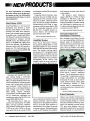


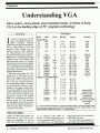


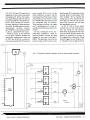


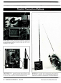


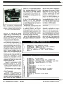


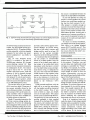
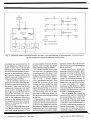


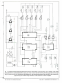
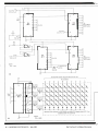

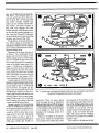


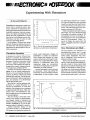

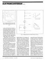

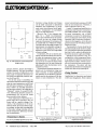
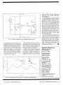

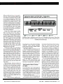


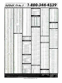


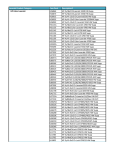


![v .] jCg _ 1l(_ `o,C..NN EinCOR `1_11E1](http://vs1.manualzilla.com/store/data/005961751_1-73960e1521729271050e00b8575619b8-150x150.png)