1
Micriµm
Empowering Embedded Systems
μC/OS-II
μC/Probe
and the
NXP LPC2478 Processor
(Using the Embedded Artists LPC2478 OEM Evaluation Board)
Application Note
AN-1478
www.Micrium.com
Micriµm
µC/OS-II and µC/Probe for the NXP LPC2478 CPU
About Micriµm
Micriµm provides high-quality embedded software components in the industry by way of engineer-friendly
source code, unsurpassed documentation, and customer support. The company‟s world-renowned realtime operating system, the Micriµm µC/OS-II, features the highest-quality source code available for
today's embedded market. Micriµm delivers to the embedded marketplace a full portfolio of embedded
software components that complement µC/OS-II. A TCP/IP stack, USB stack, CAN stack, File System
(FS), Graphical User Interface (GUI), as well as many other high quality embedded components.
Micriµm‟s products consistently shorten time-to-market throughout all product development cycles. For
additional information on Micriµm, please visit www.micrium.com.
About µC/OS-II
Thank you for your interest in µC/OS-II. µC/OS-II is a preemptive, real-time, multitasking kernel.
µC/OS-II has been ported to over 45 different CPU architectures and now, has been ported to the
Embedded Artists LPC2478 OEM evaluation board which includes the ARM-based NXP LPC2478
processor.
µC/OS-II is small yet provides all the services you would expect from an RTOS: task management, time
and timer management, semaphore and mutex, message mailboxes and queues, event flags an much
more.
You will find that µC/OS-II delivers on all your expectations and you will be pleased by its ease of use.
Licensing
µC/OS-II is provided in source form for FREE evaluation, for educational use or for peaceful research. If
you plan on using µC/OS-II in a commercial product you need to contact Micriµm to properly license its
use in your product. We provide ALL the source code with this application note for your convenience and
to help you experience µC/OS-II. The fact that the source is provided DOES NOT mean that you can
use it without paying a licensing fee. Please help us continue to provide the Embedded community with
the finest software available. Your honesty is greatly appreciated.
2
Micriµm
µC/OS-II and µC/Probe for the NXP LPC2478 CPU
About µC/Probe
μC/Probe is a Windows application that allows a user to display and change the value (at run-time) of
virtually any variable or memory location on a connected embedded target. The user simply populates
μC/Probe‟s graphical environment with gauges, tables, graphs, and other components, and associates
each of these with a variable or memory location. Once the application is loaded onto the target, the user
can begin μC/Probe‟s data collection, which will update the screen with variable values fetched from the
target.
μC/Probe retrieves the values of global variables from a connected embedded target and displays the
values in an engineer-friendly format. The supported data-types are: booleans, integers, floats and ASCII
strings.
μC/Probe can have any number of „data screens‟ where these variables are displayed. This allows to
logically grouping different „views‟ into a product.
Currently, there are two different trial version of μC/Probe :
The Full-Featured Trial Package (30-Day Evaluation Period)
Untimed Trial Package (15-Symbol Maximum)
Both versions can be downloaded on the Micriµm website :
http://www.micrium.com/products/probe/trialprobe.html
3
Micriµm
µC/OS-II and µC/Probe for the NXP LPC2478 CPU
Manual Versions
If you find any errors in this document, please inform us and we will make the appropriate corrections for
future releases.
Version
Date
By
Description
V.1.00
2008/08/11
FT
Initial version.
Software Versions
This document may or may not have been downloaded as part of an executable file, Micrium-NXP-uCOSII–LPC2478-EA.exe, containing the code and projects described here. If so, then the versions of the
Micriµm software modules in the table below would be included. In either case, the software port
described in this document uses the module versions in the table below
Module
Version
Comment
μC/OS-II
V2.86
ARM Port V1.84
μC/OS-Probe
V2.00
See Also
In addition to the µC/OS-II project accompanying this application note, a pre-compiled µC/OS-II and
µC/GUI example can be found on the NXP LPC24xx page on the Micriµm website.
4
Micriµm
µC/OS-II and µC/Probe for the NXP LPC2478 CPU
Document Conventions
Numbers and Number Bases
Hexadecimal numbers are preceded by the “0x” prefix and displayed in a monospaced font.
Example: 0xFF886633.
Binary numbers are followed by the suffix “b”; for longer numbers, groups of four digits are
separated with a space. These are also displayed in a monospaced font. Example: 0101 1010
0011 1100b.
Other numbers in the document are decimal.
prevailing where the number is used.
These are displayed in the proportional font
Typographical Conventions
Hexadecimal and binary numbers are displayed in a monospaced font.
Code excerpts, variable names, and function names are displayed in a monospaced font.
Functions names are always followed by empty parentheses (e.g., OS_Start()). Array names
are always followed by empty square brackets (e.g., BSP_Vector_Array[]).
File and directory names are always displayed in an italicized serif font.
/Micrium/Sofware/uCOS-II/Source/.
Example:
A bold style may be layered on any of the preceding conventions—or in ordinary text—to more
strongly emphasize a particular detail.
Any other text is displayed in a sans-serif font.
5
Micriµm
µC/OS-II and µC/Probe for the NXP LPC2478 CPU
Table of Contents
1.
Introduction
7
2.
2.01
2.02
2.03
2.03.01
2.05
2.05.0
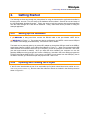
Getting Started
Setting up the Hardware
Opening and Viewing the Project
Using the IAR Project
µC/OS-II Kernel Awareness
Example Application
Additional Information
9
9
9
11
11
12
13
3.
Directories and Files
15
4.
4.01
4.02
Application Code
app.c
os_cfg.h
18
18
21
5.
5.01
5.03
5.04
5.05
Board Support Package (BSP)
IAR-Specific BSP Files
BSP, bsp.c and bsp.h
BSP, bsp_i2c.c
Processor Initialization Function
23
23
24
25
25
6.
μC/Probe
28
Licensing
31
References
31
Contacts
31
6
Micriµm
µC/OS-II and µC/Probe for the NXP LPC2478 CPU
1.
Introduction
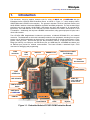
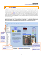
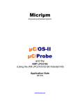
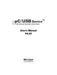
This document, AN-1478, explains example code for using µC/OS-II and µC/OS-Probe with the
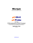
Embedded Artists LPC2478 OEM Evaluation Board, as shown in Figure 1-1, which employs NXP‟s
ARM7TDMI-based LPC2478 microcontroller. The processor includes 512 kB on-chip flash memory and
64-kB SRAM in addition to dedicated SRAM for the EMAC and DMA peripherals. The chip includes serial
interfaces such as an internal 10/100 EMAC, USB device and host (with support for an external OTG
2
transceiver), two CAN channels, a SPI controller, two SSP controllers, four UARTs, and several I C and
2
I S interfaces . Additionally, the chip has a SD/MMC card interface, many general purpose I/O pins, and a
10-bit A/D converter.
The LPC2478 OEM daughterboard includes the processor, a National DP83848 PHY, and external
memories. The baseboard on which this is situated provides the user peripherals, including five user push
buttons (one of which is attached to an interrupt line), one potentiometer, on 3-axis accelerometer, a 5-key
joystick and four LEDs. One RS-232 port (for the processor‟s UART2), a USB port used for a serial
bridge (for UART0), one CAN port, one USB device port, one USB host port, a SD/MMC card holder, and
an Ethernet port provide for external communication. The board includes a standard 20-pin JTAG
connector for debugging and programming.
JTAG
connector
USB
Host
Ethernet
SD/MMC Card
UART #0 (over USB-toSerial Bridge)
3- Axis
Accelerometer
DC Adaptor
Potentiometers
USB
OTG/Device
QVGA TFT
color LCD with
touch screen
NXP LPC2478
UART #1/UART #2
Select
UART #2 for
µC/OS-Probe
UART #1
Push Buttons
LEDs
Joystick
Figure 1-1. Embedded Artists LPC2478 OEM Evaluation Board
7
Micriµm
µC/OS-II and µC/Probe for the NXP LPC2478 CPU
If this appnote was downloaded in a packaged executable zip file, then it should have been found in the
directory /Micrium/Appnotes/AN1xxx-RTOS/AN1478-uCOS-II-NXP-LPC2478 and the code files referred to
herein are located in the directory structure displayed in Section 2.02; these files are described in
Section 3.
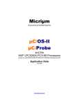
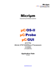
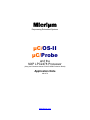
The executable zip also includes example workspaces for µC/Probe. µC/Probe is a Windows program
which retrieves the value of variables form a connected embedded target and displays the values in an
engineer-friendly format. It interfaces with the NXP LPC2378 via RS-232C. For more information,
including instructions for downloading a trial and the demo version of the program, please refer to
Section 6.
Figure 1-2. µC/Probe (with Target Output Window)
8
Micriµm
µC/OS-II and µC/Probe for the NXP LPC2478 CPU
2.
Getting Started
The following sections step through the prerequisites for using the demonstration application described in
this document, AN-1478. First, the setup of the hardware will be outlined. Second, the use and setup of
the IAR Embedded Workbench project. Thirdly, the steps to build the projects and load the application
onto the board through the JTAG will be described. Lastly, instructions will be provided for using the
example application.
2.01
Setting up the Hardware
If µC/OS-Probe is being used then connect the RS-232 cable to the port labeled “UART #2 for
µC/OS-Probe” in Figure 1-1. The project can also be configured to use UART0—which uses a USB port
via a USB-to-serial bridge (described below). See Section 2.05 for details.
The board can be powered either by an external DC adapter or through the USB port used for the USB-toserial bridge (labeled “UART0 (over USB-to-Serial Bridge in Figure 1-1. When first connecting the USB
cable between the evaluation board and your computer, you will be prompted to install the FTDI driver
(see the board manual for details). Once you have this driver installed, your computer can use this
particular USB port on the board port as if it were a COM port. Included in this is the ability to program the
LPC2478 through the UART0 (ISP). If you want to use UART0 (or use power from this USB port), but do
not want to use ISP, you will need to open the jumpers “RST” and “P2.10”
2.02
Opening and Viewing the Project
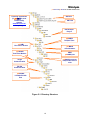
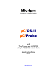
If this file were downloaded as part of an executable zip file (which should have been named MicriumNXP-uCOS-II-LPC2478-EA.exe), then the code files referred to herein are located in the directory structure
shown in Figure 2-1.
9
Micriµm
µC/OS-II and µC/Probe for the NXP LPC2478 CPU
Licensing agreements
(If µC/OS-II is used
commercially)
Contact
www.Micrium.com
for pricing
AN-1014
AN-1478
IAR Example
Project
µC/OS-II
The Real Time
Kernel
µC/LIB
Run-Time Libraries
µC/OS-II
documentation
µC/Probe
Real-Time Monitor
ARM
µC/OS-II port
µC/OS-II processor
independent source
code
Target
Communication
RS-232
Communication
µC/Probe
LPC24xx RS-232
Port
Figure 2-1. Directory Structure
10
Micriµm
µC/OS-II and µC/Probe for the NXP LPC2478 CPU
2.03
Using the IAR Project
An IAR project file named LPC2478-EA-OS-Probe-v5-2.eww is located in the directory (marked “IAR
Example Project” in Figure 2-2)
/Micrium/Software/EvalBoards/NXP/LPC2478-EA/IAR/OS-Probe
To view this example project, start an instance of IAR EWARM, and open the workspace file LPC2478EA-OS-Probe-V5-2.eww. To do this, select the “Open” menu command under the “File” menu, select the
“Workspace…” submenu command and select the workspace file after navigating to the project directory.
The project tree shown in Figure 2-3 should appear. (In addition, the workspace should be openable by
double-clicking on the file itself in a Windows Explorer window.)
The example project, LPC2478-EA-OS-Probe-v5-2.eww, is intended for EWARM v5.2x.
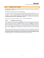
2.03.01
µC/OS-II Kernel Awareness
When running the IAR C-Spy debugger, the μC/OS-II Kernel Awareness Plug-In can be used to provide
useful information about the status of μC/OS-II objects and tasks. If the μC/OS-II Kernel Awareness
Plug-In is currently enabled, then a “μC/OS-II” menu should be displayed while debugging. Otherwise, the
plug-in can be enabled. Stop the debugger (if it is currently active) and select the “Options” menu item
from the “Project” menu. Select the “Debugger” entry in the list box and then select the “Plugins” tab
pane. Find the μC/OS-II entry in the list and select the check box beside the entry, as shown in Figure
2-2.
When the code is reloaded onto the evaluation board, the “μC/OS-II” menu should appear. Options are
included to display lists of kernel objects such as semaphores, queues, and mailboxes, including for each
entry the state of the object. Additionally, a list of the current tasks may be displayed, including for each
task pertinent information such as used stack space, task status, and task priority, in addition to showing
the actively executing task. An example task list for this project is shown in Figure 2-7.
11
Micriµm
µC/OS-II and µC/Probe for the NXP LPC2478 CPU
Figure 2-2. Enabling the μC/OS-II Kernel Awareness Plug-In
Figure 2-3. µC/OS-II Task List for LPC2478-EA-OS-Probe-V5-2.ewp
2.05
Example Application
Once the program is loaded onto the target, the LEDs will begin turning on, one-by-one. The LEDs will
then be all turned off. If any of the push buttons have been pressed since this last occurred, then the
corresponding LEDs (the LEDs directly above those push buttons) will blink rapidly 20 times.
The potentiometer controls the delay between the lighting of the LEDs in the initial phase; turning the
potentiometer counter-clockwise will decrease the delay. Similarly, the left-hand potentiometer controls
the rate at which the LEDs blink which correspond to the pressed push buttons; turning the potentiometer
counter-clockwise will decrease the delay.
Also, Text will be output to the RS-232 port labeled as “UART #0 (over USB-to-Serial Bridge)” (at 115200
baud) giving the state of the system as shown in Figure 2-3. The joystick (pressing to the left or to the right
) can be used to change the output to a new item.
12
Micriµm
µC/OS-II and µC/Probe for the NXP LPC2478 CPU
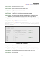
To communicate with the board through RS-232, connect a serial cable between the evaluation board
serial port and your PC and open a HyperTerminal or any Terminal program window. Configure the RS232 interface with the following settings:
Bits per Second: 115200
Data bits 8
Parity: None
Stops bits: 1
Flow Control: None
Figure 2-3. Example Application serial output
The RS-232 port labeled as “UART #2” is used for µC/Probe (at 115200 baud), which allows you to view
(in real-time) the value of static / global variables in the target system.
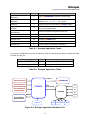
2.05.0
Additional Information
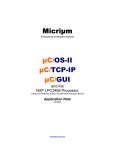
Including the µC/OS-II system tasks, the example application includes ten tasks, as listed in Table 2-1.
The board hardware used in the application is diagrammed in Figure 2-4.
13
Micriµm
µC/OS-II and µC/Probe for the NXP LPC2478 CPU
Task Name
App_TaskStart()
“Start Task”
App_TaskKbd()
“Keyboard”
App_TaskProbeStr()
“Probe Str”
App_TaskJoy()
“Joystick”
App_TaskSer ()
“Serial RS232
“Probe OS PlugIn”
Priority
Function
1
Starts µC/OS-Probe; reads ADCs, blinks LEDs.
2
Reads status of push buttons; passes IDs of pressed
buttons to App_TaskStart() in a queue.
3
Outputs strings to the Windows µC/Probe program
4
Increment/decrement the state of the system screens
base on the joystick status.
5
Outputs information through the RS-232 port
6
Updates CPU usage for µC/Probe.
“Probe RS-232”
11
Parses packets from µC/Probe.
“uC/OS-II Tmr”
29
Manages µC/OS-II timers
“uC/OS-II Stat”
30
Collect stack usage statistics
“uC/OS-II Idle”
31
Executes when no other task is executing.
Table 2-1. Example Application Tasks
The project is configured so that code is loaded into Flash and the stacks and data are loaded into RAM,
as shown in Table 2-2.
Size
Memory Range
0x00000000- 0x0007FFFF
Segment(s)
512 kB
Code (in Flash)
0x40000000- 0x4000FFFF
64 kB
Stacks and data (in RAM)
Table 2-2. Example Application Tasks
UART2
µC/OS-Probe
Accelerometer X
Accelerometer Y
2
I C0
(0.27, P0.28)
LPC2478
Accelerometer Z
Potentiometer
B1
B2
PCA9532
UART0
B3
B4
Serial Output
HyperTerminal
Joystick
LED1 LED2 LED3 LED4
Figure 2-4. Example Application Hardware Use
14
Micriµm
µC/OS-II and µC/Probe for the NXP LPC2478 CPU
3.
Directories and Files
Application Notes
\Micrium\AppNotes\AN1xxx-RTOS\AN1014-uCOS-II-ARM
This directory contains AN-1014.pdf, the application note describing the ARM port for μC/OS-II,
and AN-1014-PPT.pdf, a supplement to AN-1014.pdf.
\Micrium\AppNotes\AN1xxx-RTOS\AN1478-uCOS-II-NXP-LPC2478
This directory contains this application note, AN-1478.pdf.
Licensing Information
\Micrium\Licensing
Licensing agreements are located in this directory. Any source code accompanying this appnote
is provided for evaluation purposes only. If you choose to use μC/OS-II in a commercial product,
you must contact Micriμm regarding the necessary licensing.
μC/OS-II Files
\Micrium\Software\uCOS-II\Doc
This directory contains documentation for μC/OS-II.
\Micrium\Software\uCOS-II\Ports\ARM\Generic\IAR
This directory contains the standard processor-specific files for the generic μC/OS-II ARM port
assuming the IAR toolchain and the ARM/Keil “RealView Microprocessor Development Kit”
toolchain.
These files could easily be modified to work with other toolchains (i.e.,
compiler/assembler/linker/locator/debugger); however, the modified files should be placed into a
different directory. The following files are in this directory:
os_cpu.h
os_cpu_a.asm
os_cpu_c.c
os_dcc.c
os_dbg.c
With this port, μC/OS-II can be used in either ARM or Thumb mode. Thumb mode, which
drastically reduces the size of the code, was used in this example, but compiler settings may be
switched (as discussed in Section 2.30) to generate ARM-mode code without needing to change
either the port or the application code. The ARM/Thumb port is described in application note AN1014 which is available from the Micrium web site.
\Micrium\Software\uCOS-II\Source
This directory contains the processor-independent source code for μC/OS-II.
15
Micriµm
µC/OS-II and µC/Probe for the NXP LPC2478 CPU
μC/Probe Files
\Micrium\Software\uC-Probe\Communication\Generic\
This directory contains the μC/Probe generic communication module, the target-side code
responsible for responding to requests from the μC/Probe Windows application (including
requests over RS-232).
\Micrium\Software\uC-Probe\Communication\Generic\Source
This directory contains probe_com.c and probe_com.h, the source code for the generic
communication module.
\Micrium\Software\uC-Probe\Communication\Generic\OS\uCOS-II
This directory contains probe_com_os.c, which is the μC/OS-II port for the μC/Probe generic
communication module.
\Micrium\Software\uC-Probe\Communication\Generic\Source\RS-232
This directory contains the RS-232 specific code for μC/Probe generic communication module,
the target-side code responsible for responding to requests from the μC/Probe Windows
application over RS-232
\Micrium\Software\uC-Probe\Communication\Generic\Source\RS-232\Source
This directory contains probe_rs232.c and probe_rs232.h, the source code for the generic
communication module RS-232 code.
\Micrium\Software\uC-Probe\Communication\Generic\Source\RS-232\Ports\NXP\LPC24xx
This directory contains probe_rs232c.c and probe_rs232c.h, the NXP LPC24xx port for the RS-232
communications.
\Micrium\Software\uC-Probe\Communication\Generic\Source\RS-232\OS\uCOS-II
This directory contains probe_rs232_os.c, which is the μC/OS-II port for the μC/Probe RS-232
communication module.
μC/CPU Files
\Micrium\Software\uC-CPU
This directory contains cpu_def.h, which declares #define constants for CPU alignment,
endianness, and other generic CPU properties.
\Micrium\Software\uC-CPU\ARM\IAR
This directory contains cpu.h and cpu_a.s. cpu.h defines the Micriμm portable data types for 8-,
16-, and 32-bit signed and unsigned integers (such as CPU_INT16U, a 16-bit unsigned integer).
These allow code to be independent of processor and compiler word size definitions. cpu_a.s
contains generic assembly code for ARM7 and ARM9 processors which is used to enable and
disable interrupts within the operating system.
This code is called from C with
OS_ENTER_CRITICAL() and OS_EXIT_CRITICAL().
μC/LIB Files
\Micrium\Software\uC-LIB
This directory contains lib_def.h, which provides #defines for useful constants (like DEF_TRUE
and DEF_DISABLED) and macros.
16
Micriµm
µC/OS-II and µC/Probe for the NXP LPC2478 CPU
\Micrium\Software\uC-LIB\Doc
This directory contains the documentation for μC/LIB.
Application Code
\Micrium\Software\EvalBoards\NXP\LPC2478-EA\IAR\OS-Probe
This directory contains the source code the example application:
app.c contains the test code for the example application including calls to the functions
that start multitasking within μC/OS-II, register tasks with the kernel, and update the user
interface (the LEDs and the push buttons). app_cfg.h is a configuration file specifying
stack sizes and priorities for all user tasks and #defines for important global application
constants.
includes.h is the master include file used by the application.
os_cfg.h is the μC/OS-II configuration file.
LPC2478-EA-OS-Probe-v5-2.* are the IAR Embedded Workbench project files.
LPC2478-EA-OS-Probe-Workspace.wsp is an example µC/Probe workspace.
\Micrium\Software\EvalBoards\NXP\LPC2478-EA\IAR\BSP
This directory contains the Board Support Package for the Embedded Artists LPC2478 OEM
evaluation board:
bsp.c contains the board support package functions which initialize critical processor
functions (e.g., the PLL) and provide support for peripherals such as the push button and
potentiometer. bsp.h contains prototypes for functions that may be called by the user.
2
bsp_i2c.c contains a port for the NXP LPC2478 I C interface, aimed specifically at
supporting the PCA9532 LED dimmer which controls the LEDs and push buttons on the
board.
cstartup.s performs critical processor initialization (such as the initialization of task stacks),
readying the platform to enter main().
LPC2478_Flash.icf is the IAR linker files which contain information about the placement of
data and code segments in the processor‟s memory map.
LPC2478_Flash.mac contains instructions that are executed prior to loading code onto the
processor.
17
Micriµm
µC/OS-II and µC/Probe for the NXP LPC2478 CPU
4.
Application Code
The example application described in this appnote, AN-1478, is a simple demonstration of μC/OS-II and
μC/OS-Probe for the NXP LPC2478 processor on the Embedded Artists LPC2478 OEM evaluation
board.
4.01
app.c
Five functions of interest are located in app.c:
1. main() is the entry point for the application, as it is with most C programs. This function
initializes the operating system, creates the primary application task, App_TaskStart(), begins
multitasking, and exits.
2. App_TaskStart(), after creating the user interface tasks, enters an infinite loop in which it
blinks the LEDs (at rates determined by the potentiometers) and checks a queue to see if push
buttons have been pressed (see Figure 2-14).
3. App_TaskKbd()polls the user inputs—the push buttons—and, if new input is detected, places a
message in a queue for App_TaskStart().
4. App_TaskJoy()monitors the state of the joystick and passes messages to App_TaskSer()
5. App_TaskSer(),Outputs the state of the system based on the display state passed to it by
App_TaskJoy().
int
{
main (void)
CPU_INT08U
/* Note 1 */
err;
BSP_IntDisAll();
/* Note 2 */
OSInit();
/* Note 3 */
OSTaskCreateExt((void (*)(void *)) App_TaskStart,
/* Note 4 */
(void
*) 0,
(OS_STK
*)&AppTaskStartStk[APP_CFG_TASK_START_STK_SIZE - 1],
(INT8U
) APP_CFG_TASK_START_PRIO,
(INT16U
) APP_CFG_TASK_START_PRIO,
(OS_STK
*)&AppTaskStartStk[0],
(INT32U
) APP_CFG_TASK_START_STK_SIZE,
(void
*) 0,
(INT8U
)(OS_TASK_OPT_STK_CHK | OS_TASK_OPT_STK_CLR));
#if (OS_TASK_NAME_SIZE > 13)
/* Note 5 */
OSTaskNameSet(APP_CFG_TASK_START_PRIO, (CPU_INT08U *)"Start Task", &err);
#endif
OSStart();
/* Note 6 */
}
Listing 4-1, main()
18
Micriµm
µC/OS-II and µC/Probe for the NXP LPC2478 CPU
Listing 4-1, Note 1: As with most C applications, the code starts in main().
Listing 4-1, Note 2: All interrupts are disabled to make sure the application does not get interrupted until it
is fully initialized.
Listing 4-1, Note 3: OSInit() must be called before creating a task or any other kernel object, as must
be done with all μC/OS-II applications.
Listing 4-1, Note 4: At least one task must be created (in this case, using OSTaskCreateExt() to
obtain additional information about the task). In addition, μC/OS-II creates either one or two
internal tasks in OSInit(). μC/OS-II always creates an idle task, OS_TaskIdle(), and will
create a statistic task, OS_TaskStat() if you set OS_TASK_STAT_EN to 1 in os_cfg.h.
Listing 4-1, Note 5: As of V2.6x, you can now name μC/OS-II tasks (and other kernel objects) and
display task names at run-time or with a debugger. In this case, the App_TaskStart() is given
the name “Start Task”. Because C-Spy can work with the Kernel Awareness Plug-In available
from Micriμm, task names can be displayed during debugging.
Listing 4-1, Note 6: Finally multitasking under μC/OS-II is started by calling OSSTart(). μC/OS-II will
then begin executing App_TaskStart() since that is the highest-priority task created (both
OS_TaskStat() and OS_TaskIdle() having lower priorities).
19
Micriµm
µC/OS-II and µC/Probe for the NXP LPC2478 CPU
static void App_TaskStart (void *p_arg)
{
CPU_INT08U
i;
CPU_INT08U
j;
void
*msg;
CPU_INT08U
err;
CPU_INT08U
led;
CPU_INT32U
leds;
CPU_INT32U
delay0;
CPU_INT32U
delay1;
(void)p_arg;
BSP_Init();
/* Note 1 */
#if (OS_TASK_STAT_EN > 0)
OSStatInit();
#endif
/* Note 2 */
#if (APP_CFG_PROBE_COM_EN == DEF_ENABLED)
App_ProbeInit();
#endif
/* Note 3 */
App_EventCreate() ;
App_TaskCreate();
/* Note 4 */
BSP_Ser_Init(115200);
BSP_LED_Off(0);
while (DEF_TRUE) {
/* Note 5 */
for (i = 1; i <= 4; i++) {
/* Note 6 */
BSP_LED_On(i);
delay0 = BSP_ADC_GetStatus(BSP_ADC_POT) + 32;
OSTimeDlyHMSM(0, 0, delay0 / 1000, delay0 % 1000);
}
BSP_LED_Off(0);
delay0 = BSP_ADC_GetStatus(BSP_ADC_POT);
OSTimeDlyHMSM(0, 0, delay0 / 1000, delay0 % 1000);
leds = 0;
while (1) {
msg = OSQAccept(AppKbdQ, &err);
/* Note 7 */
if (err == OS_Q_EMPTY || msg == (void *)0) {
break;
}
led
= (CPU_INT32U)msg;
if (led > 4) {
break;
}
leds |= (1 << led);
}
if (leds == 0) {
continue;
}
for (j = 0; j < 20; j++) {
/* Note 8 */
for (i = 1; i <= 4; i++) {
if ((leds & (1 << i)) == (1 << i)) {
BSP_LED_Toggle(i);
}
}
delay1 = (BSP_ADC_GetStatus(BSP_ADC_POT) >> 2) + 32;
OSTimeDlyHMSM(0, 0, delay1 / 1000, delay1 % 1000);
}
}
}
Listing 4-2, App_TaskStart()
20
Micriµm
µC/OS-II and µC/Probe for the NXP LPC2478 CPU
Listing 4-2, Note 1: BSP_Init() initializes the Board Support Package—the I/Os, tick interrupt, etc.
See Section 5 for details.
Listing 4-2, Note 2: OSStatInit() initializes μC/OS-II‟s statistic task. This only occurs if you enable
the statistic task by setting OS_TASK_STAT_EN to 1 in os_cfg.h. The statistic task measures
overall CPU usage (expressed as a percentage) and performs stack checking for all the tasks
that have been created with OSTaskCreateExt() with the stack checking option set.
Listing 4-2, Note 3: If µC/OS-Probe is enabled, then the module‟s initialization procedure
App_ProbeInit() is called. App_ProbeInit()calls OSProbe_Init() which initializes the
µC/Probe plug-in for µC/OS-II, which maintains CPU usage statistics for each task,
ProbeCom_Init() that initializes the µC/Probe generic communication module and
ProbeRS232_Init() that initializes the RS-232 communication module. After these have been
initialized, the µC/Probe Windows program will be able to download data from the processor.
For more information, see Section 6.
Listing 4-2, Note 4: App_EventCreate()Creates all the application uC/OS-II events and
App_TaskCreate()creates all the application tasks.
Listing 4-2, Note 5: Any task managed by µC/OS-II must either enter an infinite loop „waiting‟ for some
event to occur or terminate itself. This task enters an infinite loop in which it toggles the LEDs at
rates determined by the potentiometer settings.
Listing 4-2, Note 6: The four LEDs are turned on, one by one, and then all of the LEDs are turned off.
Listing 4-2, Note 7: The task checks the queue AppKbdQ to see if any messages have been posted.
Listing 4-2, Note 8: If messages were posted (indicating that push buttons were pressed), then the LEDs
corresponding to the pressed push buttons will be blinked 20 times. If no messages were posted,
then the task will have continued at the beginning of the loop.
4.02
os_cfg.h
The file os_cfg.h is used to configure µC/OS-II and defines the maximum number of tasks that your
application can have, which services will be enabled (semaphores, mailboxes, queues, etc.), the size of
the idle and statistic task and more. In all, there are about 60 or so #define that you can set in this file.
Each entry is commented and additional information about the purpose of each #define can be found in
Jean Labrosse‟s book, µC/OS-II, The Real-Time Kernel, 2nd Edition. os_cfg.h assumes you have
µC/OS-II V2.83 or higher but also works with previous versions of µC/OS-II.
Task sizes for the Idle (OS_TASK_IDLE_STK_SIZE), statistics OS_TASK_STAT_STK_SIZE) and
timer (OS_TASK_TMR_STK_SIZE) task are set to 128 OS_STK elements (each is 4 bytes) and
thus each task stack is 512 bytes. If you add code to the examples make sure you account for
additional stack usage.
OS_DEBUG_EN is set to 1 to provide valuable information about µC/OS-II objects to IAR‟s C-Spy
through the Kernel Awareness plug-in. Setting OS_DEBUG_EN to 0 should some code space
(though it will not save much).
OS_LOWEST_PRIO is set to 31, allowing up to 32 total tasks.
21
Micriµm
µC/OS-II and µC/Probe for the NXP LPC2478 CPU
OS_MAX_TASKS determines the number of “application” tasks and is currently set to 10 allowing 9
more tasks to be added to the example code.
OS_TICKS_PER_SEC is set to 1000 Hz. This value can be changed as needed and the proper
tick rate will be adjusted in bsp.c if you change this value. You would typically set the tick rate
between 10 and 1000 Hz. The higher the tick rate, the more overhead µC/OS-II will impose on
the application. However, you will have better tick granularity with a higher tick rate.
22
Micriµm
µC/OS-II and µC/Probe for the NXP LPC2478 CPU
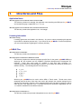
5.
Board Support Package (BSP)
The Board Support Package (BSP) provides functions to encapsulate common I/O access functions and
make porting your application code easier. Essentially, these files are the interface between the
application and the Embedded Artists LPC2478 OEM board. Though one file, bsp.c, contains some
functions which are intended to be called directly by the user (all of which are prototyped in bsp.h), the
other files serve the compiler (as with cstartup.s79).
5.01
IAR-Specific BSP Files
The BSP includes three files intended specifically for use with IAR tools: LPC2478_Flash.icf,
LPC268_Flash.mac, cstartup.s. These serve to define the memory map and initialize the processor prior to
loading or executing code. If the example application is to be used with other toolchains, the services
provided by these files must be replicated as appropriate.
Before the processor memories can be programmed, the compiler must know where code and data
should be placed. IAR requires a linker command file, such as LPC2478_Flash.icf that provides directives
to accomplish this. The C-Spy macro files LPC2478_Flash.mac declares routines which will be executed
prior to loading code on the processor and after a processor reset. Each of these sets the MEMMAP
register as is appropriate for the location of the exception vectors.
In cstartup.s is code which will be executed prior to calling main. One important inclusion is the
specification of the exception vector table (as required for ARM cores) and the setup of various exception
stacks. After executing, this function branches to the IAR-specific ?main function, in which the processor
is further readied for entering application code.
23
Micriµm
µC/OS-II and µC/Probe for the NXP LPC2478 CPU
5.03
BSP, bsp.c and bsp.h
The file bsp.c implements several global functions, each providing some important service, be that the
initialization of processor functions for μC/OS-II to operate or the toggling of an LED. Several local
functions are defined as well to perform some atomic duty, initializing the I/O for the LED or initialize the
µC/OS-II tick timer. The discussion of the BSP will be limited to the discussion of the global functions
that might be called from user code (and may be called from the example application).
The global functions defined in bsp.c (and prototyped in bsp.h) may be roughly divided into two categories:
critical processor initialization and user interface services. Four functions constitute the former:
BSP_Init() is called by the application code to initialize critical processor features (particularly
the μC/OS-II tick interrupt) after multitasking has started (i.e., OS_Start() has been called).
This function should be called before any other BSP functions are used. See Listing 5-1 for more
details.
BSP_IntDisAll() is called to disable all interrupts, thereby preventing any interrupts until the
processor is ready to handle them.
BSP_CPU_ClkFreq() returns the clock frequency in Hz.
BSP_CPU_PclkFreq() returns the clock frequency in Hz or a peripheral clock; an ID for the
peripheral clock (as defined in bsp.h) is accepted as the argument.
Five function provide access to user interface components:
BSP_LED_Toggle(), BSP_LED_On() and BSP_LED_Off() will toggle, turn on, and turn off
(respectively) the LED corresponding to the ID passed as the argument If an argument of 0 is
provided, the appropriate action will be performed on all LEDs. Valid IDs are 1, 2, 3, and 4.
BSP_PB_GetStatus() takes as its argument the ID of a push button and returns DEF_TRUE if
the push button is being pressed and DEF_FALSE if the push button is not being pressed. Valid
IDs are 1, 2, 3, and 4.
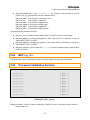
BSP_ADC_GetStatus() takes as its argument the ID of a ADC and returns the 10-bit number
that, when divided by 0x3FF, is equal to the ratio of the input voltage divided by the reference
voltage. The ID parameter can take the following values:
BSP_ADC_ACC_X the AD0.0 channel, Accelerometer x-axis.
BSP_ADC_ACC_Y the AD0.1 channel, Accelerometer y-axis.
BSP_ADC_ACC_Z the AD0.2 channel, Accelerometer z-axis.
BSP_ADC_POT the AD0.2 channel, Potentiometer.
BSP_Joy_GetPos() return the position of the Joystick . There are 6 different values that this
function can return:
BSP_JOY_NONE
BSP_JOY_UP
BSP_JOY_DOWN
BSP_JOY_RIGHT
BSP_JOY_LEFT
BSP_JOY_PUSH
If the Joystick is not being pressed.
If the Joystick is toggled up.
If the Joystick is toggled down.
If the Joystick is toggled right.
If the Joystick is toggled left.
If the Joystick is being pressed.
24
Micriµm
µC/OS-II and µC/Probe for the NXP LPC2478 CPU
BSP_JOY_GetStatus() return DEF_TRUE if the Joystick is being pressed at a given
position. The joy_pos argument can take 6 different values:
BSP_JOY_NONE
BSP_JOY_UP
BSP_JOY_DOWN
BSP_JOY_RIGHT
BSP_JOY_LEFT
BSP_JOY_PUSH
If the Joystick is not being pressed.
If the Joystick is toggled up.
If the Joystick is toggled down.
If the Joystick is toggled right.
If the Joystick is toggled left.
If the Joystick is being pressed.
Six function provide access to serial port:
BSP_Ser_Init() initializes either UART0, UART1 or UART2 for serial communication.
BSP_Ser_WrByte() and BSP_Ser_WrStr() write a byte (such as a character) or string to
either UART0, UART1 or UART2.
BSP_Ser_RdByte() and BSP_Ser_RdStr() read a byte (such as a character) or string from
either UART0, UART1 or UART2.
BSP_Ser_Printf() can be called like printf() to provide formatted output on either UART0,
UART1 or UART2.
5.04
BSP, bsp_i2c.c
This file includes a port for the NXP LPC2478 I2C interface targeted at supporting the PCA9532.
5.05
void
{
Processor Initialization Function
BSP_Init (void)
BSP_PLL_Init();
/* Note 1
*/
BSP_RTC_Init();
/* Note 2
*/
BSP_MAM_Init();
/* Note 3
*/
BSP_GPIO_Init();
/* Note 4
*/
BSP_Joy_Init();
/* Note 5
*/
BSP_ADC_Init();
/* Note 6
*/
BSP_VIC_Init();
/* Note 7
*/
BSP_I2C_Init();
/* Note 8
*/
BSP_Tmr_TickInit();
/* Note 9 */
}
Listing 5-1, BSP_Init()
Listing 5-1, Note 1: The PLL is setup to generate a 72 MHz CPU clock. All peripheral clocks are set to
half the CPU clock.
25
Micriµm
µC/OS-II and µC/Probe for the NXP LPC2478 CPU
Listing 5-1, Note 2: The Real-Time clock (RTC) is setup.
Listing 5-1, Note 3: The Memory Acceleration Module (MAM) is setup.
Listing 5-1, Note 4: The general purpose I/O ports are setup.
Listing 5-1, Note 5: The Joystick I/O is initialized.
Listing 5-1, Note 6 The ADC used for the Accelerometer/potentiometer is initialized..
Listing 5-1, Note 7: The interrupt controller is initialized, including the disabling of all interrupts and the
assignment of a dummy ISR handler to each interrupt vector to catch spurious interrupts.
2
Listing 5-1, Note 8: The I C interface used for the PCA9532 (which controls the LEDs and push buttons)
is initialized.
Listing 5-1, Note 9: The µC/OS-II tick interrupt source is initialized.
Listings 5-2 and 5-3 give the μC/OS-II timer tick initialization function, BSP_Tmr_TickInit(), the tick
ISR handler, BSP_Tmr_TickISR_Handler(). These may serve as examples for initializing an interrupt
and servicing that interrupt.
static void BSP_Tmr_TickInit (void)
{
CPU_INT32U pclk_freq;
CPU_INT32U rld_cnts;
VICIntSelect
VICVectAddr4
VICIntEnable
&= ~(1 << VIC_TIMER0);
= (CPU_INT32U)BSP_Tmr_TickISR_Handler;
= (1 << VIC_TIMER0);
pclk_freq
=
BSP_CPU_PclkFreq(BSP_PCLK_TIMER0);
rld_cnts
=
pclk_freq / OS_TICKS_PER_SEC;
T0TCR
T0TCR
T0PC
=
=
=
T0MR0
T0MCR
=
=
rld_cnts;
3;
T0CCR
T0EMR
T0TCR
=
=
=
0;
0;
1;
/* Note 1 */
/* Note 2 */
(1 << 1);
0;
0;
/* Note 3 */
/* Note 4 */
}
Listing 5-2, Tmr_TickInit()
Listing 5-2, Note 1: The timer interrupt vector is set and the interrupt is enabled.
Listing 5-2, Note 2: The peripheral clock frequency is calculated, and this clock frequency and desired
tick rate—OS_TICKS_PER_SEC—are used to determine the number of clocks between interrupts.
Listing 5-2, Note 3: The timer is setup to generate a periodic interrupt and then reset to zero.
Listing 5-2, Note 4: The timer is started.
26
Micriµm
µC/OS-II and µC/Probe for the NXP LPC2478 CPU
void BSP_Tmr_TickISR_Handler (void)
{
T0IR
= 0xFF;
/* Note 1 */
OSTimeTick();
/* Note 2 */
}
Listing 5-3, BSP_Tmr_TickISR_Handler()
Listing 5-3, Note 1: The interrupt is cleared.
Listing 5-3, Note 2: OSTimeTick() informs μC/OS-II of the tick interrupt.
27
Micriµm
µC/OS-II and µC/Probe for the NXP LPC2478 CPU
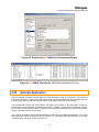
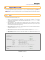
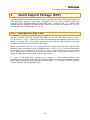
6.
μC/Probe
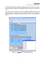
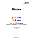
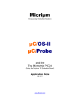
µC/Probe is a Windows program which retrieves the values of global variables from a connected
embedded target and displays the values in a engineer-friendly format. To accomplish this, an ELF file,
created by the user‟s compiler and containing the names and addresses of all the global symbols on the
target, is monitored by µC/Probe. The user places components (such as gauges, labels, and charts) into
a Data Screen in a µC/Probe workspace and assigns each one of these a variable from the Symbol
Browser, which lists all symbols from the ELF file. The symbols associated with components placed on
an open Data Screen will be updated after the user presses the start button (assuming the user‟s PC is
connected to the target).
A small section of code resident on the target receives commands from the Windows application and
responds to those commands. The commands ask for a certain number of bytes located at a certain
address, for example, “Send 16 bytes beginning at 0x0040102C”. The Windows application, upon
receiving the response, updates the appropriate component(s) on the screens with the new values.
Start Button.
This button
switches
between Design
and Run-Time
Views. During
Run-Time View
(when data is
collected), this
will appear as a
stop button (a
blue square).
Data Screen.
Symbol Browser.
Contains all symbols from the
ELF files added to the
workspace.
Figure 6-1. µC/Probe Windows Program
28
Components are placed
onto the data screen and
assigned symbols during
Design View. During RunTime View, these
components are updated
with values of those
symbols from the target
Micriµm
µC/OS-II and µC/Probe for the NXP LPC2478 CPU
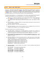
To use µC/Probe with the example project (or your application), do the following:
1. Download and Install µC/Probe. A trial version of µC/Probe can be downloaded from the
Micriµm website at
http://www.micrium.com/products/probe/probe.html
1. Open µC/Probe. After downloading and installing this program, open the example µC/Probe
workspace for µC/OS-II, named OS-Probe-Workspace.wsp, which should be located in your
installation directory at
/Program Files//Micrium/uC-Probe/Target/Plugins/uCOS-II/Workspace
2. Connect Target to PC. Currently, µC/Probe can use RS-232 to retrieve information from the
target. You should connect a RS-232 cable between your target and computer.
3. Load Your ELF File. The example projects included with this application note are already
configured to output an ELF file. (If you are using your own project, please refer to Appendix A of
the µC/Probe user manual for directions for generating an ELF file with your compiler.) This file
should be in
/<Project Directory>/<Configuration Name>/exe/
where <Project Directory> is the directory in which the IAR EWARM project is located (extension
*.ewp) and <Configuration Name> is the name of the configuration in that project which was built
to generate the ELF file and which will be loaded onto the target. The ELF file will be named
<Project Name>.elf
in EWARM v4.4x and
<Project Name>.out
in EWARM v5.xx unless you specify otherwise. To load this ELF file, right-click on the symbol
browser and choose “Add Symbols”.
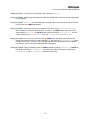
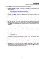
4. Configure the RS-232 Options. In µC/Probe, choose the “Options” menu item on the “Tools”
menu. A dialog box as shown in Figure 6-2 (left) should appear. Choose the “RS-232” radio
button. Next, select the “RS-232” item in the options tree, and choose the appropriate COM port
and baud rate. The baud rate for the projects accompanying this appnote is 115200.
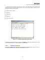
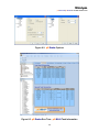
5. Start Running. You should now be ready to run µC/Probe. Just press the run button (
) to
see the variables in the open data screens update. Figure 6-3 displays the µC/OS-II workspace
which displays detailed information about each task‟s state.
29
Micriµm
µC/OS-II and µC/Probe for the NXP LPC2478 CPU
Figure 6.2. µC/Probe Options
Figure 6-3. µC/Probe Run-Time: µC/OS-II Task Information
30
Licensing
μC/OS-II is provided in source form for FREE evaluation, for educational use or for peaceful research. If
you plan on using μC/OS-II in a commercial product you need to contact Micriμm to properly license its
use in your product. We provide ALL the source code with this application note for your convenience and
to help you experience μC/OS-II. The fact that the source is provided does NOT mean that you can use it
without paying a licensing fee. Please help us continue to provide the Embedded community with the
finest software available. Your honesty is greatly appreciated.
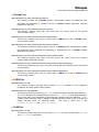
References
µC/OS-II, The Real-Time Kernel, 2nd Edition
Jean J. Labrosse
R&D Technical Books, 2002
ISBN 1-57820-103-9
Embedded Systems Building Blocks
Jean J. Labrosse
R&D Technical Books, 2000
ISBN 0-87930-604-1
Contacts
IAR Systems
Century Plaza
1065 E. Hillsdale Blvd
Foster City, CA 94404
USA
+1 650 287 4250
+1 650 287 4253 (FAX)
e-mail: [email protected]
WEB : www.IAR.com
CMP Books, Inc.
1601 W. 23rd St., Suite 200
Lawrence, KS 66046-9950
USA
+1 785 841 1631
+1 785 841 2624 (FAX)
e-mail: [email protected]
WEB : http://www.cmpbooks.com
Micriµm
949 Crestview Circle
Weston, FL 33327
USA
+1 954 217 2036
+1 954 217 2037 (FAX)
e-mail: [email protected]
WEB : www.Micrium.com
NXP
1110 Ringwood Court
San Jose, CA 95131
USA
+1 408 474 8142
WEB : www.nxp.com