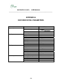
1
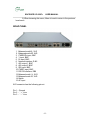
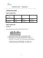
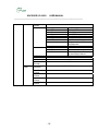
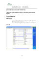
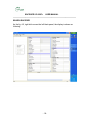
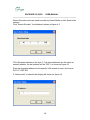
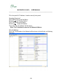
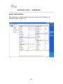
ENCODER UC-250E+ USER MANUAL
________________________________________________________________
UC-250E+
MPEG 2 ENCODER
USER MANUAL
Version 2.01 031508
UPCOM TECHNOLOGIES INC.
www.upcomtechnologies.com
-1-
ENCODER UC-250E+ USER MANUAL
________________________________________________________________
CONTENT
INTRODUCTION ..................................................................................................3
INTRODUCTION...............................................................................................3
WORKING PRINCIPLE.....................................................................................3
FUNCTIONS .....................................................................................................4
ENVIRONMENT................................................................................................4
INSTALLATION ....................................................................................................5
FRONT PANEL .................................................................................................5
REAR PANEL....................................................................................................6
OPERATION GUIDE ............................................................................................7
BASIC OPERATION .........................................................................................7
MENU OPERATION..........................................................................................7
START UP .....................................................................................................7
MENU STRUCTURE.........................................................................................8
MENU STRUCTURE .....................................................................................9
FRONT PANEL OPERATION .........................................................................11
PARAMETER SETTINGS............................................................................11
VERSION INFORMATION...........................................................................11
MODIFY PASSWORD.................................................................................11
FACTORY MODE........................................................................................11
KEYBOARD LOCK ......................................................................................12
AUDIO MENU SETTINGS ...........................................................................12
BIT RATE.....................................................................................................12
AUDIO MODE..............................................................................................12
NETWORK MANAGEMENT OPERATION .....................................................17
OPERATION STEPS...................................................................................17
SPECIFICATIONS ..........................................................................................24
TECHNOLOGY PARAMETERS......................................................................24
REFERENCE STANDARDS ...........................................................................24
DEFINITIONS..................................................................................................25
APPENDIX A ......................................................................................................26
ENCODER INITIAL PARAMETERS ...................................................................26
-2-
ENCODER UC-250E+ USER MANUAL
________________________________________________________________
INTRODUCTION
INTRODUCTION
The UC-250E+ encoder supports the following audio inputs: balanced, unbalanced and digital. It supports the following video inputs: CVBS, S-video,
Y/Pb/Pr and SDI digital interface. It supports two programs multiplexed into a TS
transport stream. It has two ASI outputs, with the same TS. It can work
independently or remotely controlled by a computer, by means of Web Based
Network Management Program.
WORKING PRINCIPLE
The encoder consists of the following modules: video front end module, audio
front end module, video encoding module, audio encoding module, interface
module, multiplexer module and control module.
The video/audio front end modules convert the analog signals to digital signals.
The audio and video encoding modules process the digital signal and produce
MPEG-2 Transport Stream. Interface module processes the Transport Stream to
ASI format output
The multiplexer module packets audio stream, video stream and other streams to
the standard stream output.
The control module sets up, loads and controls other modules. It also processes
the interface with an external computer for Network Management.
-3-
ENCODER UC-250E+ USER MANUAL
________________________________________________________________
FUNCTIONS
-SDI digital video input, CVBS input and component Y, Pr, Pb input
- Balanced, Stereo Audio Inputs
-MPEG-2 4:2:0 MP@ML video encoding, encode bit-rate range: 1.5-15MBit/s
-Variable GOP
-RJ45 interface
-Human-machine interface: LED, 160x32 LCD and 6 control keys
-The parameters will be restored in the event of an abnormal power off.
ENVIRONMENT
Working temperature: 0 to 55 C
Working humidity: 5 to 80%
Storage temperature: -20 to 80 C
Storage humidity: 5 to 90%
-4-
ENCODER UC-250E+ USER MANUAL
________________________________________________________________
INSTALLATION
FRONT PANEL
The front panel is shown in figure 2-1. It includes a LCD screen, 3 LED indicators
and 6 buttons.
-
Six buttons: LEFT, DOWN, RIGHT, UP, MENU, OK. These buttons are
used to select the Menu and set up the parameters.
Four LED indicators:
LED 1 is power indicator: LED on means the power is on.
LED 2 is the status LED1. LED on means it is encoding and no LED
means the input channel is closed.
LED 3 is the status LED 2. LED on means it is encoding and no LED
means the input channel is closed.
LED 4 is the temperature warning LED. Red LED on means the
temperature higher than setting temperature.
The usage of the buttons is:
DOWN: move menu down or changing value/parameters;
UP: move menu up changing value/parameters;
RIGHT: move the cursor to the right;
LEFT: move the cursor to the left;
OK:
1) When setting up the parameters, OK is used to confirm the set up
and return to the previous-level menu.
2) When browsing the menu, it enters the next level-menu;
MENU: 1) When setting up the parameters, Menu is used to cancel the setup
and return to the previous-level menu;
-5-
ENCODER UC-250E+ USER MANUAL
________________________________________________________________
2) When browsing the menu, Menu is used to return to the previouslevel menu.
REAR PANEL
1. Balanced audio2L, XLR
2. Balanced audio2R, XLR
3. CVBS2/Pb input, BNC
4. Y input, BNC
5. Pr input, BNC
6. Network interface, RJ45
7. ASI output 1, BNC
8. ASI output 2, BNC
9. SDI input, BNC
10. CVBS1 input, BNC
11. RS-232 interface, DB9
12. Balanced audio1 L, XLR
13. Balanced audio1R, XLR
14. Switch
15. AC input
XLR connector has the following pin-out:
Pin 1 – Ground
Pin 2 - “ + “ Line
Pin 3 - “ – “ Line
-6-
ENCODER UC-250E+ USER MANUAL
________________________________________________________________
OPERATION GUIDE
BASIC OPERATION
Step
Application
Installation
Change
Parameters
First
Second
Third
Network
Setting
Logon
Network
Logon
Network
Read
Information
Read
Information
Modify
Parameters
MENU OPERATION
START UP
After loading the software, the display will show as follows:
PGM1
PGM2
6.0
6.0
Unlock
Off
1. Output program number: PGM1 is output program number 1
2. Output bit rate: 6.0 M is output program number 1 bit rate
3. Output program running status: if a signal is input, it is shown as
“PAL/NTSC”, if it is showing “Off”, it will not start the output program.
1.” Main Menu” switch to “Operation Menu”: click “Menu” key
2.”Operation Menu” switch to “Main Menu” : click “Menu” key
-7-
ENCODER UC-250E+ USER MANUAL
________________________________________________________________
MENU STRUCTURE
The operation menu has four levels. The first level menu has four menu items,
each has its own child menu. And the child menu has its own child menus again.
When encoding, the user can change these parameters with following steps:
1. Press “MENU” to enter the encoder to change parameters.
2. After changing parameter, press “OK” and return to system menu to save
the setting.
3. No matter how the encoder is changed, press “MENU” to return last level
menu.
Note: If the display is kept still for above sixty seconds, the LCD will return to
main menu.
-8-
ENCODER UC-250E+ USER MANUAL
________________________________________________________________
MENU STRUCTURE
Status
Running
Setting
First
Keyboard
lock
Version
info
Factory
Mode
System
option
Second
Third
Fourth
Display bit rate
Soft: 1.0 hard: 0.1
Network
Address
IP address
Subnet mask
Gateway
Modify
password
Device number
Warm
Temperature
Output on/off
Set
Program1
Set
program2
Program
number
Set Video
Video input
CVBS1/SDI
Video PID
0x20 – 0x1FFD
Video bit rate
1.5-15Mbps
Video signal
PAL/NTSC
Video
D1/half-D1/SIF/Q-SIF
resolution
GOP
I/IP/IPB/IPBB
Structure
Spatial filter
Soft/Standard/sharp
Graphic
Brightness/Contrast/Chroma hue/saturation
Quality
Encode Mode CBR/VBR
Audio input
Analog1/SDI
Set audio1
Audio PID
0x20x0x1FFD
Audio bit rate
Audio mode
Stereo/Joint Stereo/Dual Channel/Single Channel
Audio PID
0x20-0x1FFD
Set Audio 2
Audio Bit rate
Audio Mode
Stereo/Joint Stereo/Dual Channel/Single Channel
XXXX HEX
PMT PID
XXXX HEX
PCR PID
ASCII
Service name
ASCII
Service provider
Output on/off
-9-
ENCODER UC-250E+ USER MANUAL
________________________________________________________________
Program
number
Set Video
Set Audio
Set Analog
Radio
Video input
Video PID
Video Bit rate
Video Signal
Video Resolution
GOP Structure
Spatial Filter
Graphic Quality
Encode Mode
Audio PID
Audio Bit rate
Audio Mode
PMT PID
PCR PID
Service name
Service
Provider
Sampling
frequency
CVBS Y/Pb/Pr
0x20-0x1FFD
1.5-15Mbps
PAL/NTSC
D1/HELF-D1/SIF/Q-SIF
I/IP/IPB/IPBB
Soft/Standard/sharp
Brightness/Contrast/Chroma
hue/Saturation
CBR/VBR
0x20-0x1FFD
Stereo/Joint Stereo/Dual
channel/Single Channel
XXXX Hex
XXXX Hex
ASCII
ASCII
32000/44100/48000
Input1 L
Volume
Input1 R
Volume
Input2 L
Volume
Input2 R
Volume
40
40
40
40
- 10 -
ENCODER UC-250E+ USER MANUAL
________________________________________________________________
FRONT PANEL OPERATION
PARAMETER SETTINGS
VERSION INFORMATION
Operation Sequence:
Click “MENU” to enter next Menu, select “VERSION INFO” then click “OK”. The
display will show as following:
Version Info
Soft: 1.0
Hard: 0.1
The screen is for information only, the user can not change the parameters.
MODIFY PASSWORD
Operation Sequence:
Click “MENU” to next menu, select by
key “ System option”;
Then click “OK” key into the second menu;
Select “Password Modify” to click “OK”, the display is shown as following:
Password Modify
Click “
“ in
“-“, click each symbol, the Cursor Move a bit;
Password consists of 8 symbols, factory password is “
can change the password.
“, the user
FACTORY MODE
Operation Sequence:
Click “MENU” to the first menu, select by
Then click “OK” to finish the setting.
key to “ Manufactory Mode”;
Note: After this operation the System will return to the original Factory Setting.
- 11 -
ENCODER UC-250E+ USER MANUAL
________________________________________________________________
KEYBOARD LOCK
Operation Sequence:
Click “MENU” to the first menu, select by
key “ Keyboard Lock” then click
“OK” key to finish the function. In order to use the front panel again you will need
to open the Keyboard Lock.
AUDIO MENU SETTINGS
The UC-250E+ Encoder supports the following audio parameters selections:
audio input, audio PID, audio bit rate, sampling rate, audio mode and volume
BIT RATE
Operation Sequence:
Click “MENU” to the first menu, select by
key “Set Program 1” or “Set
Program 2”;
Then click “OK” key to the second menu, select by
key “Audio 1” or “Audio
2”;
Then click “OK” to the third menu, select by
key “Bit Rate”;
Then click “OK” key to set the Audio Bit Rate.
Selection
X Kbps (X=32, 48, 64, 96, 112, 128, 160, 192, 224, 256, 320, 384)
BIT RATE
192 Kbps
Explanation: Select Bit Rate value by
key.
AUDIO MODE
Operation Sequence:
Click “MENU” to the first menu, select by
key “Program 1” or “Program 2”,
click “OK” to the second menu;
Then select by
key “Audio 1” or “Audio 2”;
Click “OK” to the third menu;
Select by
key “Bit Rate”;
- 12 -
ENCODER UC-250E+ USER MANUAL
________________________________________________________________
Click “OK” to “Audio Mode” setting.
Selection:
Stereo/Joint Stereo/Dual Channel/Single Channel
AUDIO MODE
STEREO
SAMPLING FREQUENCY
Operation Sequence:
Click “MENU” to the first Menu, select by
Key “Analog Audio”;
Click “OK” to the second Menu;
Select by
Key “Sampling Frequency”;
Then click “OK” Key to set Sampling Frequency.
Selection:
32KHz/44.1 KHz/48 KHz
SAMPLING FREQUENCY
48.0 KHz
VOLUME
Operation Sequence:
Click “MENU” to the first Menu, select by
Then click “OK”;
Set volume by
Key
INPUT L VOLUME
Volume: 40
- 13 -
Key: “Analog Audio”;
ENCODER UC-250E+ USER MANUAL
________________________________________________________________
VIDEO MENU SETTINGS
The UC-250E+ Encoder supports the following video parameters selections:
video input, video PID, video bit rate , video signal, video resolution, GOP
structure, spatial filter, graphic quality, and encoding mode.
VIDEO INPUT
The encoder supports two types of video inputs: CVBS1/SDI and CVBS2/Y/Pb/Pr
Operation Sequence:
Click “MENU” to the first Menu, select by
Click “OK” Key to the second Menu;
Select by
Key “Set Video”;
Click “OK” Key to the third Menu;
Select by
Key “Video Input”;
Then click “OK” to select video input
Key “Program 1” or “Program 2”;
Possible Selections:
Program 1 Video Input: CVBS1/SDI
Program 2 Video Input: CVBS2/Y/Pb/Pr
VIDEO INPUT
CVBS1/SDI
VIDEO PID
Operation Sequence:
Click “MENU” to the first Menu, select by
Click “OK” Key to the second Menu;
Select by
Key “Set Video”;
Then click “OK” Key to the third Menu;
Select by
Key “Video PID”;
Then click “OK” to set PID.
The video PID Range is 0x20 to 0x1FFD
VIDEO PID
PID: 33
- 14 -
Key “Program1” or :Program2”;
ENCODER UC-250E+ USER MANUAL
________________________________________________________________
VIDEO BIT RATE
Operation Sequence:
Click “MENU” to the first Menu, select by
Click “OK” Key to the second Menu;
Select by
Key “Set Video”;
Then click “OK” Key to the third Menu;
Select by
Key “Video Bit Rate”;
Then click “OK” to set Bit Rate.
Range: 1-15Mbps
Key “Program 1” or “Program 2”;
VIDEO SIGNAL
Video signal type can be selected to NTSC or PAL
GOP STRUCTURE
The GOP structure can be selected as I, IP, IPB, IPBB. The structure I requires
the maximum bit rate and the IPBB requires the minimum.
Operation Sequence:
Click “MENU” to the first Menu, select by
Click “OK” Key to the second Menu;
Select by
Key “Set Video”
Then click “OK” Key to the third Menu;
Select by
Key “GOP Structure”;
Click “OK” Key to GOP Structure setting.
Key “Program 1” or “Program 2”;
GOP Structure
IPBB
SPATIAL FILTER
Spatial Filter parameter including: Soft/Normal/Sharp/Soft show the picture soft,
sharp show picture sharp.
SPATIAL FILTER
NORMAL
- 15 -
ENCODER UC-250E+ USER MANUAL
________________________________________________________________
GRAPHIC QUALITY
Graphic Quality including: Brightness/Contrast/Chroma Hue/Saturation. Video
Picture Quality has some change by adjustment these parameters.
ENCODE MODE
Possible Selections:
CBR/VBR
ENCODE MODE
CBR
VIDEO RESOLUTION
Video Resolution display output picture quality, selected video resolution is
connected to Bit Rate.
DI definition is the best. Q-SIF definition is the lowest resolution.
Possible Selections:
DI, Half-DI, SIF, Q-SIF
VIDEO RESOLUTION
DI
Note:
1- If modified video PID is same as other PID, the display will show
“used”, at that time you can modify PID by
2- If appear the same PID value through making over the PID, the
system will give a clue to the user
3- During make over the PID, you should think over other equipment
which connect the encoder
4- After making over the IP address you need return system to save
the set and avoid set unsuccessful shut off the encoder
- 16 -
ENCODER UC-250E+ USER MANUAL
________________________________________________________________
NETWORK MANAGEMENT OPERATION
The Encoder can be managed by means of a Web-Based Remote Manager
program.
OPERATION STEPS
INSTALATION
Insert the CD into the host computer and unzip the zipped file;
The unzipped file is setup exe.
Go on following the system prompt and then run encoder exe.
LOG ON
- 17 -
ENCODER UC-250E+ USER MANUAL
________________________________________________________________
SEARCH ENCODER
As the fig. 4-2, right click mouse the left blank panel, the display is shown as
following:
- 18 -
ENCODER UC-250E+ USER MANUAL
________________________________________________________________
Search Encoder mode can search encoder by Search Mode or Add Mode in the
network.
Click “Search Encoder”, the interface is shown as figure 4-3:
Fill in Broadcast Address in the fig 4-3, First three addresses are the same as
network address, the last address will be “255”, it is shown as figure 4-3
Enter the broadcast address for the specific LAN network in use in the format
XXX.YYY.ZZZ.255.
If “add encoder” is selected the display will shown as figure 4-4
- 19 -
ENCODER UC-250E+ USER MANUAL
________________________________________________________________
Fill in the specific IP Address, it can be seen by front panel;
Operation Sequence”
Click “MENU” key to the first Menu;
Select by
key “System Option”;
Click “OK” to the second Menu;
Select by
“Network Address”;
Then click “OK”,”IP Address” will be shown.
Note: The IP Address is same as the Network Address
Fill in IP Address;
Click “OK”, the Encoder in the Network will be shown in the left side, as following
figure 4-5
- 20 -
ENCODER UC-250E+ USER MANUAL
________________________________________________________________
READ CONFIGURATION
After searching or adding Encoder, right click mouse in the IP Address, the
display will show as figure 4-6:
- 21 -
ENCODER UC-250E+ USER MANUAL
________________________________________________________________
As figure 4-6, click “Read Configuration”, the Encoder parameters will show at
the display, at the same time the computer LED turn to green, as following figure
4-7:
- 22 -
ENCODER UC-250E+ USER MANUAL
________________________________________________________________
After reading configuration, select a Encoder, then modify the parameters by
remotely, after modification, fill in 654321 in password and new password
column, then enter “Write Configuration” operation, so modify parameter
procedure is finished.
WRITE CONFIGURATION
Write Configuration is the operation to save parameters. After adjustment of
equipment parameters it is needed to click “Write Configuration” to ensure the
parameter takes effect;
Operation steps are:
As figure 4-6, right click mouse in the left side;
Click “Write Configuration”;
The display will pop “set configuration success”, the parameter modify
successfully.
- 23 -
ENCODER UC-250E+ USER MANUAL
________________________________________________________________
SPECIFICATIONS
TECHNOLOGY PARAMETERS
Bit Rates: 2M-25M; VBR, O-CBR, I-CBR (ASI)
Output Ports: two ASI, RJ45
Human-Machine interface: LED LED, LCD Screen, Background adjustment
button
Power-off protection: the device will restore the parameter in the case of poweroff
Remote controlled by computer
Dimension: 484 (W) X 44 (H) X 306 (D) mm
Weight: about 5 Kg
Power consumption: 25W
REFERENCE STANDARDS
GB/T 17975
GY/T 170-2001
- 24 -
ENCODER UC-250E+ USER MANUAL
________________________________________________________________
DEFINITIONS
DVB: Digital Video Broadcasting
TS: Transport Stream
SPTS: Single Program Transport Stream
MPTS: Multiple Program Transport Stream
ASI: Asynchronous Serial Interface
DCT: Discrete Cosine Transform
GOP: Group of Pictures
SPI: Synchronous Parallel Interface
VBR: Variable Bit Rate
CBR: Constant Bit Rate
- 25 -
ENCODER UC-250E+ USER MANUAL
________________________________________________________________
APPENDIX A
ENCODER INITIAL PARAMETERS
System Option
Set Program 1
Set Program 2
Set Analog Audio
IP Address
Password modify
Device
Warm temp.
Output
Program number
Set Video
Set Audio 1
Set Audio 2
PMT PID
PCR PID
Service Name
Service Provider
Output
Program Number
Set Video
Set Audio
PMT PID
PCR PID
Service Name
Service Provider
Sampling Frequency
Input1 L Volume
Input1 R Volume
Input2 L Volume
Input1 R Volume
- 26 -
PARAMETER
200.121.002.250
1
70
On
1
CVBS
Analog 1
Audio PID=0
32
33
DVB-Program1
DVB-Server
Off
1
CVBS
Audio PID=66
0
65
DVB-Program2
DVB-Server
48Mhz
40
40
40
40