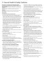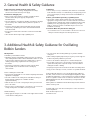
1
Original Instruction Manual
BBS1 Benchtop Bobbin Sander
BBS2 Heavy Duty
Floorstanding Bobbin Sander
Version 3.0
August 2013
To register this product please visit
www.recordpower.info
It is important to register your product as soon as possible in order to receive efficient after sales
support and be entitled to the full 5 year guarantee. Your statutory rights are not affected.
Please see back cover for contact details.
Kg
i
Always wear safety glasses when
using woodworking equipment.
Always read the instructions
provided before using
woodworking equipment.
Important
For your safety read instructions carefully before
assembling or using this product.
Save this manual for future reference.
1
Contents
1 Explanation of Symbols
2 General Health & Safety Guidance
3 Additional Health & Safety Guidance for Oscillating Bobbin Sanders
4 Record Power Guarantee
5 Specifications
6 Features of the BBS1 & BBS2 Bobbin Sanders
7 Contents of the Packages
8 Assembly
9 Operation
10 Dust Extraction
11 Maintenance
12 Electrical Connection & Wiring Diagram
13 Troubleshooting
14 Parts Lists & Diagrams
EU Declaration of Conformity
2
1. Explanation of Symbols
The symbols and their meanings shown below may
be used throughout this manual.
Please ensure that you take the appropriate action
wherever the warnings are used.
Mandatory Instructions
i
Read and fully understand the instruction
manual before attempting to use
the machine.
Indicates an instruction that requires
particular attention
Wear protective eyewear
i
i Use respiratory protective equipment
i
i
i
i
Use hearing protection
Use suitable protective footwear
Use protective work gloves
Warnings
Indicates a risk of severe personal injury
or damage to the machine
Indicates a risk of severe personal injury
from electrical shock
Kg
i
Kg
Kg
Kg
Risk of personal injury from lifting of
heavy items
i
i personal injury
Indicates a risk of severe
i objects
from airborne
Risk of fire
Kg
i
3
2. General Health & Safety Guidance
Ensure that you carefully read and fully understand the
instructions in this manual before assembly, installation and
use of this product. Keep these instructions in a safe place for
future reference.
•If the machine is suitable to be used on a workbench, ensure that the
workbench is well constructed and capable of withstanding the weight
of the machine. The machine should always be securely fastened to the
workbench with appropriate fixings.
WARNING: for your own safety, do not attempt to operate this machine
until it is completely assembled and installed according to these
instructions.
•Where possible, floor standing machines should always be secured to the
floor with fixings appropriate to the structure of the floor.
WARNING: When using any machine, basic safety precautions should
always be followed to reduce the risk of fire, electric shock and
personal injury.
Safe Operation
1. Use Personal Protective Equipment (PPE)
•The operation of any machine can result in foreign objects being thrown
into your eyes, which can result in severe eye damage. Protective
eyewear or other suitable eye protection or face shield should be used at
all times. Everyday spectacles only have impact resistant lenses. They are
not protective eyewear and do not give additional lateral protection.
•Use respiratory protective equipment (dust mask etc.) if the machining
operation creates dust. Exposure to high levels of dust created by
machining hardwoods, softwoods and man made composite boards can
result in serious health problems. Some imported hardwoods give off
highly irritating dust, which can cause a burning sensation. The use of
respiratory protective equipment should not be seen as an alternative to
controlling the risk of exposure at source by using adequate dust
extraction equipment.
•The use of ear plugs or ear defenders is recommended when the machine
is in use, particularly if the noise level exceeds 85 dB.
•Wear suitable protective gloves when handling cutting tools or blades.
Gloves should NOT be worn when using the machine as they can be
caught in moving parts of the machine.
•Non-slip safety footwear is recommended when using the machine and
handling large work pieces.
2. Dress appropriately
•Do not wear loose clothing, neckties or jewellery; they can be caught in
moving parts of the machine.
• Roll up long sleeves above the elbow.
• Wear protective hair covering to contain long hair.
3. Safety warnings
• Find and read any warning labels on the machine
•It is important that any labels bearing health and safety warnings are
not removed, defaced or covered. Replacement labels can be obtained by
contacting our Customer Service Department.
4. Familiarise yourself with the machine
•If you are not thoroughly familiar with the operation of this machine,
obtain advice from your supervisor, instructor, or other qualified person or
contact your retailer for information on training courses. Do not use this
machine until adequate training has been undertaken.
5. Take care when moving or positioning the machine
•Some machines can be very heavy. Ensure the floor of the area
in which the machine is to be used is capable of supporting
the machine.
•The machine and its various components can be heavy.
Always adopt a safe lifting technique and seek assistance when lifting
heavy components. In some cases it may be necessary to use mechanical
handling equipment to position the machine within the work area.
•Some machines have optional wheel kits available to allow them to be
manoeuvred around the workshop as required. Care should be taken to
install these according to the instructions provided.
•Due to the nature of the design of some machines the centre of gravity
will be high making them unstable when moved. Extreme care should be
taken when moving any machine.
6. The machine should be level and stable at all times
•When using a leg stand or cabinet base that is designed to be fitted to
the machine, always ensure that it is securely fastened to the machine
using the fixings provided.
•The floor surface should be sound and level. All of the feet of the
machine should make contact with the floor surface. If they do not, either
re-locate the machine to a more suitable position or use packing shims
between the feet and the floor surface to ensure the machine is stable.
7. Remove adjusting keys and wrenches
•Ensure that all adjusting wrenches and keys are removed before
switching the machine ‘ON’. There is a risk of severe personal injury or
damage to the machine from airborne objects.
8. Before switching the machine ‘ON’
• Clear the machine table of all objects (tools, scrap pieces etc.)
•Make sure there is no debris between the work piece and the
table / work support.
•Ensure that the work piece is not pressed against, or touching the saw
blade or cutting tool.
•Check all clamps, work holding devices and fences to ensure that they
are secure and cannot move during machining operations.
•Plan the way that you will hold and feed the work piece for the entire
machining operation.
9. Whilst machining
•Before starting work, watch the machine while it runs. If it makes
an unfamiliar noise or vibrates excessively, switch the machine ‘OFF’
immediately and disconnect it from the power supply. Do not restart until
finding and correcting the source of the problem.
10. Keep the work area clear
•Working clearances can be thought of as the distances between
machines and obstacles that allow safe operation of every machine
without limitation. Consider existing and anticipated machine needs,
size of material to be processed through each machine and space for
auxiliary stands and/or work tables. Also consider the relative position of
each machine to one another for efficient material handling. Be sure to
allow yourself sufficient room to safely operate your machines in any
foreseeable operation.
•Cluttered work areas and benches create the risk of accidents. Keep
benches clear and tidy away tools that are not in use.
•Ensure that the floor area is kept clean and clear of any dust and debris
that may create trip or slip hazards.
11. Consider the work area environment
• Do not expose the machine to rain or damp conditions.
•Keep the work area well lit and ensure that there is artificial lighting
available when there is insufficient natural light to effectively light the
work area. Lighting should be bright enough to eliminate shadow and
prevent eye strain.
•Do not use the machine in explosive environments eg. in the presence of
flammable liquids, gases or dust.
•The presence of high levels of dust created by machining wood can
present a risk of fire or explosion. Always use dust extraction equipment
to minimise the risk.
12. Keep other persons away (and pets)
• The machine is designed to be used by one person only.
•Do not let persons, especially children, touch the machine or extension
cable (if used) and keep visitors away from the work area.
•Never leave the machine running unattended. Turn the power supply off
and do not leave the machine unattended until it comes to a
complete stop.
•If the work area is to be left unattended, all machinery should be
switched ‘OFF’ and isolated from the mains power supply.
4
2. General Health & Safety Guidance
13. Store machines safely when not in use
•When not in use, machines should be stored in a dry place, out of reach
of children. Do not allow persons unfamiliar with these instructions or
with the machine to operate it.
14. Do not overreach
•Choose a working position that allows your body to remain balanced
and feed the work piece in to the machine without overreaching.
• Keep proper footing and balance at all times.
15. Electrical supply
•Electrical circuits should be dedicated to each machine or large enough
to handle combined motor amp loads. Power outlets should be located
near each machine so that power or extension cables are not obstructing
high-traffic areas. Observe local electrical guidelines for proper
installation of new lighting, power outlets, or circuits.
• The machine must be connected to an earthed power supply.
•The power supply must be equipped with a circuit breaker that provides
short circuit, overload and earth leakage protection.
•The voltage of the machine must correspond to the voltage of the mains
power supply.
•The mains plug fitted to the machine should always match the power
outlet. Do not modify the plug in any way. If a replacement plug is
required it should be fitted by a competent person and of the correct
type and rating for the machine.
•If you are unsure about any electrical connections always consult a
qualified electrician.
16. Avoid unintentional starting of the machine
•Most machines are fitted with a no-volt release (NVR) switch to prevent
unintentional starting. If in doubt always ensure the machine switch
is in the ‘OFF’ position before connecting it to the power supply. This
means the machine will not automatically start up after a power cut or
switching on of the power supply, unless you first reset the start switch.
17. Outdoor use
• Your machine should not be used outdoors.
18. Extension cables
•Whenever possible, the use of extension cables is not recommended.
If the use of an extension cable is unavoidable, then it should have
a minimum core cross section of 2.5 mm² and limited to a maximum
length of 3 metres.
•Extension cables should be routed away from the direct working area to
prevent a trip hazard.
19. Guard against electric shock
•Avoid body contact with earthed or grounded surfaces such as pipes
and radiators. There is an increased risk of electric shock if your body is
earthed or grounded.
20. Always work within the machine’s intended capacities
•Operator safety and machine performance are seriously adversely
affected if attempts to make the machine perform beyond its limits
are made.
21. Do not abuse the power cable
•Never pull the power cable to disconnect it from the power socket.
Always use the plug.
• Keep the power cable away from heat, oil and sharp edges.
• Do not use the power cable for carrying or moving the machine.
• Do not attempt to machine more than one work piece at a time.
•When feeding the work piece towards the blade or cutting tool never
position your hands in direct line of the cutting path. Avoid awkward
operations and hand positions where a sudden slip could cause your
hand or fingers to move into the machining area.
23. Stay alert
•Safety is a combination of operator common sense and alertness at all
times when the machine is being used.
•Use all machines with extreme care and do not use the machine when
you are tired or under the influence of drugs, alcohol or medication.
24. Use the correct tool for the job
•Do not use the machine for any purpose other than which it
was designed.
•When selecting replacement cutting tools and blades, always ensure that
they are designed to cut the material that you intend to use them for. If
in any doubt seek further advice from the manufacturer.
25. Connect dust extraction equipment
•Always use dust extraction equipment. The dust extractor should be of
suitable size and capacity for the machine that it is connected to and
have a filtration level appropriate to the type of waste being collected.
Refer to the relevant section of the manual for details of the specific dust
extraction requirements for this machine.
•The dust extractor should be switched ‘ON’ before starting the machine
that it is connected to. The dust extractor should be left running for 30
seconds after the last machining operation is complete in order to clear
any residual waste from the machine.
26. Ensure that the machine is correctly guarded
•Never use the machine if any of the standard safety guards and
equipment are removed or damaged.
•Some machines incorporate safety interlocks to prevent the machine
from being used without the guards in place. Never attempt to bypass
or modify the interlocks to allow the machine to be used without the
guards in place.
27. Maintain your machine with care
•This manual gives clear instructions on installation, set up and
operation of the machine and also details any routine and preventative
maintenance that should be performed periodically by the user.
•Remember always to switch off and unplug the machine from the power
supply before carrying out any setting up or maintenance operations.
•Follow any instructions for the maintenance of accessories
and consumables.
•Do not use compressed air to clean the machine. Always use a brush to
dislodge dust in places that are awkward to reach and a dust extractor
to collect the waste.
•Inspect electric cables periodically and, if damaged, have them replaced
by an authorised service facility or qualified electrician.
•Inspect extension cables (if used) periodically and replace if damaged.
28. Keep cutting tools sharp and clean
•Correctly maintained cutting tools are easier to control and less likely
to bind.
•Cutting tools and blades can become hot during use. Take extreme care
when handling them and always allow them to cool before changing,
adjusting or sharpening them.
22. Secure the work piece
•Ensure that the work piece is securely held before starting to machine it.
•When working within 300 mm of the machining area, always use a push
stick to feed the work piece in to the blade or cutting tool. The push stick
should have a minimum length of 400 mm. If the push stick becomes
damaged, replace it immediately.
•Use extra supports (roller support stands etc.) for any work pieces large
enough to tip when not held down to the table top.
•Do not use another person as a substitute for a table extension, or as
additional support for a work piece that is longer or wider than the basic
table, or to help feed, support, or pull the work piece.
5
2. General Health & Safety Guidance
29. Disconnect the machine from the power supply
•When not in use, before servicing, changing blades etc. always
disconnect the machine from the power supply.
30. Check for damaged parts
•Before each use of the machine, it should be carefully checked to
determine that it will operate properly and perform its
intended function.
•Check for alignment of moving parts, binding of moving parts, breakage
of parts and any other conditions that may affect the operation of
the machine.
•A guard or other part that is damaged should be properly repaired
or replaced by a qualified person unless otherwise indicated in this
instruction manual.
•Do not use the machine if the switch does not turn the machine ‘ON’
and ‘OFF’.
31. Warning!
•The use of any accessory or attachment, other than those recommended
in this instruction manual, or recommended by our Company may present
a risk of personal injury or damage to the machine and invalidation of
the warranty.
32. Have your machine repaired by a qualified person
•This machine complies with the relevant safety rules and standards
appropriate to its type when used in accordance with these instructions
and with all of the standard safety guards and equipment in place. Only
qualified persons using original spare parts should carry out repairs.
Failure to do this may result in considerable danger to the user and
invalidation of warranty.
33. Caution! Motor may become hot during use
• It is normal for motors on some machines to become hot to the touch
during use. Avoid touching the motor directly when in use.
• Have defective switches replaced by a qualified person.
3. Additional Health & Safety Guidance for Oscillating
Bobbin Sanders
Safe Operation
1. Familiarise yourself with the machine
•Machining operations using bobbin sanders present less of a risk than
other sanding machines. Most accidents with bobbin sanders are caused
by the work piece being thrown from the sanding surface or by loose
clothing or fingers being caught between the moving parts of
the machine.
•The machine is designed for sanding wood and composite board
(plywood, MDF etc.). It should not be used for sanding any
other materials.
2. Before switching the machine ‘ON’:
•Use extra caution when working with large, very small or awkward
work pieces.
•When sanding irregularly shaped work pieces, plan your work support so
it will not slip and be pulled from your hands.
• Never use the machine to finish pieces too small to hold by hand.
•Do not apply excessive force to the work piece. Press the work piece
against the sanding surface only hard enough to let it sand without
slowing the machine or binding
• Keep fingers away from the area between the table and sanding surface.
• Keep your face and body to one side, out of line of a possible throwback.
•Check the condition of the sanding sleeve and bobbin for damage or
fraying. Defective sanding sleeve or bobbins should be
replaced immediately.
4. This machine falls under the scope of the ‘Health & Safety at Work etc.
Act 1974’, and the ‘Provision & Use of Work Equipment Regulations 1998’.
In addition the elimination or control of risks from wood dust is included in
the above regulations and the ‘Control of Substances Hazardous to Health
(COSHH) Regulations 2002’. We recommend that you study and follow
these regulations.
•Make sure there are no nails or foreign objects in the part of the work
piece to be sanded.
Further guidance is available from The Health & Safety Executive and their
website www.hse.gov.uk.
•Ensure that the sanding table is secure and that any fixings which allow
adjustment are fully tight.
•Plan your work to avoid throwbacks – the work piece can catch on the
moving sanding surface and will be torn from your hand.
For further help on any of the above matters please contact our Customer
Services Department:
3. Whilst machining:
Email: [email protected]
•Always apply the work piece to the table / work support before it makes
contact with the sanding surface.
Tel: 01246 571 020
6
4. Record Power Guarantee
“Products” means the Products sold by Record Power subject to these
terms and conditions;
“Record Power” is Record Power Limited, whose company registration
number is 4804158 and registered office address is Centenary House,
11 Midland Way, Barlborough Links, Chesterfield, Derbyshire, S43 4XA and
sells through a network of Authorised Dealers;
“Authorised Distributor” is the nominated importer for your region
who will generally sell through a network of Authorised Dealers. Details of
Authorised Distributors for specific countries can be found in the Product
manual or at www.recordpower.info;
“Authorised Dealer” is a retailer or business authorised to sell Record
Power Products to end users.
1
Guarantee
1.1 Record Power guarantees that for a period of 5 years from the date
of purchase the components of qualifying Products (see clauses 1.2.1
to 1.2.9) will be free from defects caused by faulty construction
or manufacture.
1.2 During this period Record Power, its Authorised Distributor or
Authorised Dealer will repair or replace free of charge any parts
which are proved to be faulty in accordance with paragraphs 1.1
above provided that:
1.2.1 you follow the claims procedure set out in clause 2 below;
1.2.2 Record Power, our Authorised Distributor or Authorised Dealer are
given a reasonable opportunity after receiving notice of the claim to
examine the Product;
1.2.3if asked to do so by Record Power, its Authorised Distributor or
Authorised Dealer, you return the Product, at your own cost, to
Record Power's premises or other approved premises such as those
of the Authorised Distributor or supplying Authorised Dealer, for the
examination to take place;
1.2.4the fault in question is not caused by industrial use, accidental
damage, fair wear and tear, wilful damage, neglect, incorrect
electrical connection, abnormal working conditions, failure to follow
our instructions, misuse, or alteration or repair of the Product without
our approval;
1.2.5the Product has been used in a domestic environment only;
1.2.6 the fault does not relate to consumable Products such as blades,
bearings, drive belts or other wearing parts which can reasonably
be expected to wear at different rates depending on usage (for full
details contact Record Power or your local Authorised Distributor);
2
Claims Procedure
2.1 In the first instance please contact the Authorised Dealer who
supplied the Product to you. In our experience many initial problems
with machines that are thought to be due to faulty parts are actually
solved by correct setting up or adjustment of the machines. A good
Authorised Dealer should be able to resolve the majority of these
issues much more quickly than processing a claim under
the guarantee.
2.2 Any damage to the Product resulting in a potential claim under the
guarantee must be reported to the Authorised Dealer from which it
was purchased within 48 hours of receipt.
2.3If the Authorised Dealer who supplied the Product to you has been
unable to satisfy your query, any claim made under this Guarantee
should be made directly to Record Power or its Authorised Distributor
(for details of the Authorised Distributor in your country please see
your Product manual or check www.recordpower.info for details).
The claim itself should be made in a letter setting out the date and
place of purchase, and giving a brief explanation of the problem
which has led to the claim. This letter should then be sent with
proof of the purchase date (preferably a receipt) to Record Power or
its Authorised Distributor. If you include a phone number or email
address this will help to speed up your claim.
2.4Please note that it is essential that the letter of claim reaches Record
Power or its Authorised Distributor on the last day of this Guarantee
at the latest. Late claims will not be considered.
3
Limitation of Liability
3.1 We only supply Products for domestic and private use. You agree not
to use the Product for any commercial, business or re-sale purposes
and we have no liability to you for any loss of profit, loss of business,
business interruption or loss of business opportunity.
3.2This Guarantee does not confer any rights other than those expressly
set out above and does not cover any claims for consequential loss
or damage. This Guarantee is offered as an extra benefit and does
not affect your statutory rights as a consumer.
Notice
4
This Guarantee applies to all Products purchased from an Authorised
Dealer of Record Power within the United Kingdom of Great
Britain and Northern Ireland. Terms of Guarantee may vary in other
countries – please check with the Authorised Distributor in your
country (details of the Authorised Distributor for your country can be
found in the manual or at www.recordpower.info).
1.2.7the Product has not been used for hire purposes, by you or by a
previous owner;
1.2.8 the Product has been purchased by you as the guarantee is not
transferable from a private sale.
1.2.9where the Product has been purchased from a retailer, the 5 year
guarantee is transferable and begins on the date of the first purchase
of the Product and in the event of a claim under this guarantee
proof of the original purchase date will be required to validate the
warranty period.
7
5. Specifications
BBS1
BBS2
Speed:
1400 rpm
1400 rpm
Oscillation Stroke:
24 mm
30 mm
Table size:
380 mm diameter
500 mm diameter
Table tilt:
0 - 45º
0 - 45º
Motor:
1/2 hp / 370 W / 230 V / 50 Hz
1 hp / 750 W / 230 V / 50 Hz
Full load current:
1.6 A
3.5 A
Noise emission:
Sound power level < 80.1 dB (A)
Sound power level < 80.1 dB (A)
Sound pressure level < 69.6 dB (A)
Sound pressure level < 73.5 dB (A)
6. Features of the BBS1 & BBS2 Bobbin Sanders
9
1
2
3
7
8
4
6
5
1 Sanding bobbin
6 Table insert caddy
2 Work table
7 On / off switch with emergency stop
3 Table securing knob
8 Table tilt handle
4 Machine body
9 Table insert
5 Bobbin storage caddy
8
7. Contents of the Packages
3
BBS1 Benchtop Bobbin Sander
1
2
6
4
1 BBS1 Benchtop Bobbin Sander
5
Rubber feet x 4
2
Sanding bobbin & sleeve, 20 x 90 mm
6
Table inserts x 4
3
Sanding bobbin & sleeve, 50 x 140 mm
4
17 & 14 mm open ended wrenches x 2
5
BBS2 Heavy Duty Floorstanding Bobbin Sander
1
7
4
5
3
2
6
1BBS2 Heavy Duty Floorstanding
Bobbin Sander
5
21 & 19 mm open ended wrenches x 2
6
Rubber feet x 4
2
Sanding bobbin & sleeve, 20 x 140 mm
7
Table inserts x 6
3
Sanding bobbin & sleeve, 50 x 230 mm
4
Sanding bobbin & sleeve, 76 x 230 mm
Please note: Bobbins and sleeves shown above in the machines are for illustrative purposes only.
9
8. Assembly
Fig. 8.1
Kg
Kg
Caution: The machine is heavy and may require two
i
person lifting
Remove the Bobbin Sander from the packaging. The machine comes ready
assembled apart from the sanding attachments and the rubber feet.
i
Attaching the Rubber Feet
Lower the machine onto its side. Remove the feet from the plastic
wrapping. Remove the nut and washer from the thread.
Locate the four mounting points on the underside of the machine. Insert
the thread into the hole so that the rubber foot points downward, Fig 8.1.
Put on the washer followed by the nut. Tighten with a wrench. Repeat this
operation for the other three feet.
Site the machine at a suitable height enabling sanding operation to be
carried out comfortably and safely.
Installing the Sandpaper on to the Rubber Cylinder
or Bobbins
Kg
Caution: Make sure the machine is isolated from the supply
before any maintenance, cleaning or adjustments
are undertaken.
Fig. 8.2
Nut
Compression
washer
Bobbin
Compression
washer
Sanding sleeve
Shaft
Kg
i
i
If you want to change the grade of sanding paper already attached to the
bobbins supplied with the machine then proceed as follows. The bobbin
consists of a rubber body with a shaft passing through the centre, Fig 8.2.
At either end of the body are two large compression washers.
Fig. 8.3
At the top is a nut and washer to secure the sanding sleeve. The lower part
of the shaft is threaded and locates in the motor drive.
Please note: The shaft threads at the top and bottom of the
bobbin are left handed.
Remove the nut using a suitable wrench, Fig 8.3, lift away the washer
and slide the sanding sleeve clear of the bobbin. If removal was difficult
sprinkle a smalli amount of talcum powder onto the rubber to aid fitting the
new sandpaper sleeve.
Various grades of sanding sleeve are available for different applications.
See your stockist for replacement of sanding sleeve.
Offer the sanding sleeve to the rubber body, Fig 8.4. Slide onto the rubber
body so it fits centrally with no edges overhanging.
Fig.8.4
Replace the washer and nut. With a wrench tighten the nut to expand the
rubber body. This will grip the sanding sleeve. Do not over-tighten as this
will distort the rubber body.
10
8. Assembly
Installing the Bobbin on to the Machine
Fig. 8.5
Lower the bobbin down through the top of the machine.
Locate the thread on the bobbin spindle into the thread on the motor
drive spindle.
Select two open ended wrenches, Fig 8.5. With one wrench hold the motor
drive spindle and with the other wrench tighten the bobbin spindle.
Do not over-tighten.
Selecting Table Insert
The machine comes with two types of table insert for each bobbin size.
There is one with a round opening and one with an oval opening. For 90º
sanding choose the insert with the round opening, Fig 8.6. Notice the
cutout on the edge of the table insert. This aligns with the roll pin in the
recess on the table, Fig 8.7. Lower into position making sure the table
insert locates in the recess and is flush with the table.
Checking the Table Top is Square to the Bobbin
Fig. 8.6
Using a suitable 90º square placed on the table top, move the square to the
bobbin to check alignment, Fig 8.8. If the table is not square, adjustment
can be made. Located under the work table are eccentric table stops which,
Fig 8.9. Loosen the locking knob, loosen the table stop screws then rotate
the table stops until the table is at 90º with the bobbin. Tighten the table
stop screws and locking knob. Slacken the pointer screw and align with the
0º position on the scale and re-tighten screw.
Fig. 8.7
Cutout
Pin
Fig. 8.8
Fig. 8.9
Eccentric
table stop
Scale
Locking knob
Pointer
11
9. Operation
Tilting the Table
Fig. 9.1
NOTE: Remove the table insert with the circular opening before
tilting the table, otherwise it may be damaged.
Knurled locking ring
The table will tilt 0° - 45°.
To loosen the table,
first loosen the locking knob then also loosen the
i
knurled locking ring which is located behind the table rotation handle on
the opposite side of the table trunnion, see Fig 9.1. Once the desired angle
has been achieved, tighten the two stop bolts and knurled locking ring.
Table rotation handle
Locate the table insert with the oval opening and place into the
table top, Fig 9.2.
Starting & Stopping the Bobbin Sander
Fig. 9.2
To turn the bobbin sander on, lift the red emergency stop switch on the
front of the machine body and press the green switch marked ‘I’, Fig 9.3.
To stop the machine in normal use, lift the red emergency stop button and
press the red button marked ‘O’.
To stop the machine in an emergency, press the large red emergency stop
button on the front of the machine body, Fig 9.4.
In the Event of a Blockage or if the Machine Stalls
If the bobbin sander stalls during use, simply reducing pressure on the
bobbin by removing the work piece will allow the sanding bobbin to return
to normal speed. If the bobbin sander has a tendency to stall during use,
this could indicate that either too much pressure is being exerted on the
work piece, or that the sanding sleeve is at the end of its working life and
needs to be replaced.
In the event of a blockage (for example, if the work piece becomes trapped
against a fixed part of the machine) switch off the machine immediately by
pressing the emergency stop button.
Fig. 9.3
Locate and rectify the source of the blockage and ensure that the sanding
bobbin can be rotated freely by hand before attempting to re-start the
machine. To re-start the machine, press the green button marked ‘I’ as
described above.
In the Event of a Power Failure
The bobbin sander is fitted with a no volt release (NVR) switch to protect
the user against automatic starting of the machine when the power is
restored after a power failure.
In the event of a power failure, first locate and rectify the source of the
failure. If the fault is within the power circuit of the workshop, there may be
an underlying cause (circuit overload etc.) that should be investigated by a
qualified electrician, before attempting to restore the power supply.
Fig. 9.4
Once the power is restored, the machine can be re-started by pressing the
green button marked ‘I’ on the switch as described above.
12
9. Operation
Fig. 9.5
Using the Bobbin Sander
Kg
i
Kg
Caution: Never start the machine with work in contact with
the bobbin.
Start the machine and wait until the motor has reached full speed
before using.
i
Looking from above the machine, the spindle turns in a clockwise direction,
Fig 9.5. Always feed the workpiece from right to left, in the direction
of rotation.
Using the Bobbin Sander at Angles up to 45º
Take out the round insert and store carefully. Put in the oval insert and
slacken the table securing knobs on either side of the machine. Tilt the table
to the desired angle and re-tighten the ratchet levels. Feed the work into
the machine always with the direction of rotation, Fig 9.6.
Fig. 9.6
PLEASE NOTE: Always bear in mind that when the table is tilted
the angle required will only be achieved.
i
PLEASE NOTE: To sand a workpiece to the angle of the table,
always ensure the workpiece only comes into contact with the
bobbin at the front of the machine, perpendicular to the axis of
table tilt.
i
Dust Extraction
Fig. 9.7
Both the BBS1 and BBS2 are fitted with a 50 mm diameter dust extraction
outlet, located on the rear of the machine beneath the table. See Fig 9.7.
A suitable dust extraction machine must be connected to this outlet to
minimise the user's exposure to dust.
13
10. Dust Extraction
The Importance Of Dust Extraction
Before the machine is started, ensure that adequate dust extraction
provisions have been installed. Dust extraction is extremely important not
only for health and safety but also for the correct upkeep of the machine.
Saw dust can cause the machine not to operate properly or even fail
completely. By keeping the machine free of large amounts of waste the
performance will be optimised.
If a large amounts of MDF or toxic woods are to be cut we recommend that
there is a good ventilation system in place and that in addition to proper
extraction a mask or respirator be worn as minimum protection.
Record Power Extractors
Record Power offer a range of high quality dust extractors, we offer both
drum and bag type extractors which filter down 0.5 micron providing
protection from harmful fine dusts. All Record Power dust extractors & chip
collectors have 100 mm inlets and hoses.
DX1000 High Filtration Dust Extractor
Drum type extractor, 45 litre capacity, single 1 kW motor, suitable for
intermittent use ie must be switched off for 20 minutes every hour.
0.5 micron filtration
Drum type extractor, 50 litre capacity, single 1 kW motor, suitable for
intermittent use ie must be switched off for 20 minutes every hour.
0.5 micron filtration
RSDE/2A High Filtration Dust Extractor
with Auto Switching
Drum type extractor, 50 litre capacity, single 1 kW motor, auto switching
allows the machine to be turned on and off as machines and power tools
are operated. Suitable for intermittent use ie must be switched off for 20
minutes every hour. Maximum auto switch capacity tools up to 1.1 kW.
0.5 micron filtration
Bandsaws
Circular saws
Sanders
Intermittent usage
3
3
RSDE2
3
CX2000 Compact Chip Extractor
Medium capacity chip collector, with a powerful 0.56 kW induction motor.
An extremely smooth running unit suitable for continuous usage. Very quiet
impeller system extracts dust and chippings.
CX3000 Chip Collector
Larger capacity chip collector, with a more powerful 0.75 kW induction
motor and heavy duty construction. An extremely smooth running unit
suitable for continuous usage. Very quiet impeller system extracts dust and
chippings.
RSDE2 High Filtration Dust Extractor
DX1000 RSDE1
DX5000 High Filtration Dust Extractor
Bag type extractor, 200 litre capacity, Twin 1 kW motor, suitable for heavy
usage ie if one motor is switched off for 20 minutes then the other can
be used thus enabling continuous usage. Or both motors can be used
simultaneously giving maximum suction but in this mode the extractor must
be switched off for 20 minutes every hour. 0.5 micron filtration
CX2600 Chip Collector
Large capacity chip collector, with a powerful 0.37 kW induction motor.
An extremely smooth running unit suitable for continuous usage. Very quiet
impeller system extracts dust and chippings.
Suitable for chip collection or finer dust using the optional filter
cartridge
RSDE1 High Filtration Dust Extractor
Drum type extractor, 45 litre capacity, single 1 kW motor, suitable for
intermittent use ie must be switched off for 20 minutes every hour.
0.5 micron filtration
DX4000 High Filtration Dust Extractor
Drum type extractor, 80 litre capacity, Twin 1 kW motor, suitable for heavy
usage ie if one motor is switched off for 20 minutes then the other can
be used thus enabling continuous usage. Or both motors can be used
simultaneously giving maximum suction but in this mode the extractor must
be switched off for 20 minutes every hour. 0.5 micron filtration
Suitable for chip collection or finer dust using the optional filter
cartridge
Air Cleaners
It is strongly advised to also use an air cleaner to remove the fine airborne
dust present in the workshop which cannot be removed using machine
extraction. Record Power offer a range of air cleaners suitable for all home
workshops. Please contact your preferred stockist or
visit www.recordpower.info.
RSDE/2A DX4000 DX5000 CX2000 CX2600 CX3000
3
3
3
Recommended Recommended Recommended Recommended Recommended Recommended
Bandsaws
Circular saws
Sanders
Heavy usage
3
3
Recommended Recommended
Planer Thicknessers
Spindle Moulders
Universals
Intermittent usage
Planer Thicknessers
Spindle Moulders
Universals
Heavy usage
Dust Extraction
System
Intermittent usage
3
3
Recommended Recommended
3
3
3
3
3
Can be used Recommended Recommended Recommended Recommended
3
3
Can be used Recommended
3
3
3
Recommended Recommended
3
Can be used Recommended
14
11. Maintenance
Periodic maintenance of the machine is necessary to maximise longevity
of the machine. The maintenance procedures detailed below aim to
provide guidance for most routine areas of maintenance but should not be
considered to be an exhaustive list.
After Each Use of the Machine
Clean the machine with a soft brush and use a suitable high filtration dust
extractor to remove residual waste.
Check all components for sign of wear or damage and replace as necessary.
Ensure the dust extraction outlet is clear of any obstructions and the dust
extraction machine is in full working order.
Weekly
Clean and lubricate the following parts using a silicone based spray such as
CWA195 Silicone Spray or similar dry lubricant. Do not use oil:
Table trunnion mechanism.
Bobbin spindle threads.
Table adjustment components.
Clean the worktable surface using white spirit or similar. Do not use thinners
as damage to the paint finish may occur. After cleaning, apply silicone spray
or similar to the table for added protection.
Monthly
Check for free movement and rotation of the oscillation mechanism.
If problems are found please contact Record Power for assistance.
15
12. Electrical Connection & Wiring Diagram
Machines supplied for use in the UK are fitted with a 3 pin plug conforming
to BS1363, fitted with a fuse conforming to BS1362 and appropriate to the
current rating of the machine.
machine. If replacing the original fuse, always fit a fuse of equivalent rating
to the original. Never fit a fuse of a higher rating than the original. Never
modify the fuse or fuse holder to accept fuses of a different type or size.
Machines supplied for use in other countries within the European Union are
fitted with a 2 pin Schuko plug conforming to CEE 7/7.
Where the current rating of the machine exceeds 13 A at 230 V, or if the
machine is designated for use on a 400 V 3 phase supply a connector
conforming to BS4343 (CEE17 / IEC60309) will be used.
Machines supplied for use in Australia & New Zealand are fitted with a 3 pin
plug conforming to AS/NZS3112.
In all cases, if the original plug or connector has to be replaced for any
reason, the wires within the mains power cable are colour coded as follows:
230 V machines will be fitted with a blue 3 pin connector. The wiring for this
type of this connector will be the same as shown above.
400 V, 3 phase machines will be fitted with a red 4 or 5 pin connector. The
wiring for this type of connector is as shown below:
230 V (Single Phase)
Brown:
Live (L)
400 V (3 phase)
Blue: Neutral (N)
Brown: Live (L1)
Black:
Live (L2)
Grey:
Live (L 3)
Blue:
Neutral (N)
Green and Yellow:
Earth (E)
Green and Yellow: Earth (E)
The wire coloured brown must always be connected to the terminal marked
‘L’ or coloured red.
The wire coloured blue must always be connected to the terminal marked ‘N’
or coloured black.
The wire coloured green and yellow must always be connected to the
terminal marked ‘E’ or with the earth symbol:
The wire coloured brown must always be connected to the terminal
marked ‘L1’.
The wire coloured black must always be fitted to the terminal
marked ‘L2’.
or coloured green / green and yellow.
The wire coloured grey must always be connected to the terminal
marked ‘L3’.
It is important that the machine is effectively earthed. Some machines will be
clearly marked with the double insulated logo:
The wire coloured blue must always be connected to the terminal
marked ‘N’ or coloured black.
The wire coloured green and yellow must always be connected to the
terminal marked ‘E’ or with the earth symbol
In this case there will not be an earth wire within the circuit.
In the case of the BS1363 plug for use in the UK, always ensure that it is
fitted with a fuse conforming to BS1362 appropriate to the rating of the
If in doubt about the connection of the electrical supply, always consult a
qualified electrician.
16
13. Troubleshooting
PROBLEM PROBABLE CAUSE REMEDY
Bobbin sander does not operate. Not plugged into power outlet.
Plug into power outlet.
Power switch defective.
Replace switch.
Motor or wiring problem. Have a qualified electrician carry out repair if necessary.
Faulty motor.
Replace motor.
Faulty fuse.
Check and replace the fuse with the correct rating.
Power supply fault.
Identify source of power failure and rectify.
Bobbin sander stalls or will not
Bobbin jammed.
Remove obstruction.
reach full speed.
Ensure dust extraction outlet is cleared.
Faulty capacitor.
Replace capacitor.
Low voltage supply.
Check voltage supply.
Minimise cable extension length.
Motor slows when sanding. Applying too much pressure.
Apply less pressure to the workpiece when sanding.
Sanding sleeve is clogged with debris.
Clean or replace sleeve.
Use adequate dust extraction.
Sanding sleeve is worn out.
Replace sanding sleeve.
Faulty motor.
Replace motor.
Loose sanding sleeve gives impression
Tighten the bobbin securing nut.
of slow motor performance.
Wood burns while sanding.
Sanding sleeve is clogged with debris.
Clean or replace sleeve.
Use adequate dust extraction.
Sanding sleeve is worn out.
Replace sanding sleeve.
Applying too much pressure.
Apply less pressure to the workpiece when sanding.
Sander makes excessive noise.
Loose bobbin.
Tighten bobbin.
Damaged / irregularly worn bobbin.
Replace bobbin.
Possible wear or failure of internal components.
Contact Record Power or your local stockist for assistance.
17
14. Parts Lists & Diagrams
Parts List for BBS1 - Diagram A
No.
DESCRIPTION
No.
DESCRIPTION
A-1
Machine body
A-31
Table insert
A-2
Work table bracket
A-32
Switch box
A-3
Work table bracket
A-33
Table insert caddy
A-4
Switch
A-34
Dial indicator
A-5
Work table
A-35
Cross recessed pan head screws M5 x 8 mm
A-6
Connection rod
A-36
Cross recessed pan head screws M4 x 12 mm
A-7
Rotation bracket of work table (Left)
A-37
Stepped bolt
A-8
Rotation bracket of work table (Right)
A-38
Cross recessed countersunk screws M5 x 6 mm
A-9
Ratchet handle
A-39
Cross recessed pan head tapping screws ST2.9 x 13 mm
A-10
Small gear
A-40
Hex. nut M5
A-11
Rack
A-41
Roll pin
A-12
Knurled locking ring
A-42
Cable gland M18
A-13
Rotating shaft
A-14
Washer 6 mm
A-44
Left-handed nut M10
A-15
Washer 5 mm
A-45
Convex washer
A-16
Hex. bolt M6 x 12
A-46
Rubber sleeve
A-17
Hex. bolt M8 x 16
A-47
Washer
A-18
Hex. bolt M8 x 20
A-48
Sanding sleeve
A-19
Hex. bolt M6 x 16
A-49
Hex. nut M8
A-20
Hex. bolt M5 x 16
A-50
Rubber washer
A-21
Eccentric table stop
A-51
Nut washer
A-22
Cross recessed countersunk screws M6 x 10 mm
A-52
Hex. bolt M8 x 25
A-23
Rotation handle
A-53
Cross recessed pan head screws M4 x 10 mm
A-24
Bobbin caddy
A-54
Hex. nut M10
A-25
Fixed section
A-55
Spring washer 6
A-26
Movable section
A-56
Washer 8
A-27
Oscillation assembly
A-57
Cross recessed pan head screws M6 x 12 mm
A-28
Dust extraction outlet
A-58
Bottom guard
18
14. Parts Lists & Diagrams
Diagram A
19
14. Parts Lists & Diagrams
Parts List for BBS1 - Diagram B
No.
DESCRIPTION
No.
DESCRIPTION
B-1
Motor base
B-20
Hex. thin nut M8
B-2
Bobbin spindle bushing
B-21
Splined plastic insert for bobbin spindle
B-3
Guide column
B-22
Connecting rod spacer
B-4
Worm wheel frame
B-23
Connecting rod axle
B-5
Worm wheel spindle
B-24
Cross recessed countersunk screws M4 x 6 mm
B-6
Bearing gland
B-25
Cross recessed pan head screws M5 x 8 mm
B-7
Crank axle
B-26
Hex. bolt M8 x 20 mm
B-8
Crank
B-27
Hex. bolt M6 x 16 mm
B-9
Worm wheel
B-28
Washer 8 mm
B-10
Connecting rod
B-29
Spring washer 8 mm
B-11
Bearing 6001-2RS
B-30
Self-locking nut M5
B-12
Worm gear
B-31
Circlips for shafts 5 mm
B-13
Cover, worm wheel frame
B-32
Bearing 61804
B-14
Plastic housing for worm gear
B-33
Bearing 6006
B-15
Motor B-34
Internal circlip 55 mm
B-16
Bearing cover
B-35
External circlip 30 mm
B-17
Key 4 x 4 x 12 mm
B-36
Socket head screw M5 x 6 mm
B-18
Hex. socket set screws with flat point M6 x 6
B-19
Hex. bolt M8 x 75 mm
20
14. Parts Lists & Diagrams
Diagram B
21
14. Parts Lists & Diagrams
Parts List for BBS2 - Diagram C
No.
DESCRIPTION
No.
DESCRIPTION
C-1
Rotation bracket of work table(Left)
C-31
Roll pin
C-2
Rotation bracket of work table(Right)
C-32
Hex. thin nut M10
C-3
Rack
C-33
Cross recessed pan head screws M6 x 12 mm
C-4
Work table
C-34
Bottom guard
C-5
Work table bracket
C-35
Stepped bolt
C-6
Work table bracket
C-36
Cross recessed countersunk screws M6 x 12 mm
C-7
Switch
C-37
Hex. nut M5
C-8
Rotation handle
C-38 Front panel, machine body
C-9
Rotating shaft
C-39
Cross recessed pan head tapping screws ST3 x 10 mm
C-10
Knurled locking ring
C-40
Dust extraction outlet
C-11
Small gear
C-41
Table insert
C-12
Fixed section
C-42
Bobbin storage caddy
C-13
Movable section
C-43
Hex. bolt M5 x 16 mm
C-14
Eccentric table stop
C-44
Upper cover, machine body
C-15
Oscillation assembly
C-45
Switch box
C-16
Hex. bolt M8 x 16 mm
C-46
Table insert caddy
C-17
Hex. bolt M6 x 16 mm
C-47
Rubber washer
C-18
Hex. bolt M8 x 25 mm
C-48
Cross recessed pan head screws M5 x 25 mm
C-19
Cross recessed pan head screws M6 x 12 mm
C-49
Cross recessed pan head screws M4 x 12 mm
C-20
Hex. nut M8
C-50
Cross recessed pan head tapping screws ST3 x 10 mm
C-21
Cross recessed countersunk screws M5 x 6 mm
C-51
Hex. bolt M8 x 30 mm
C-22
Washer 6 mm
C-52
Pressing pad
C-23
Washer 8 mm
C-53
Bobbin shaft
C-24
Washer 5 mm
C-54
Left-handed nut M10
C-25
Cross recessed pan head screws M5 x 8 mm
C-55
Sanding sleeve
C-26
Ratchet handle
C-56
Washer
C-27
Machine body
C-57
Washer
C-28
Spring washer 6 mm
C-58
Rubber cylinder
C-29
Rubber foot
C-59
Hex. bolt M6 x 12 mm
C-30
Nut
22
14. Parts Lists & Diagrams
Diagram C
23
14. Parts Lists & Diagrams
Parts List for BBS2 - Diagram D
No.
DESCRIPTION
No.
DESCRIPTION
D-1
Motor base
D-20
Hex. thin nut M8
D-2
Bobbin spindle
D-21
Splined plastic insert for bobbin spindle
D-3
Guide column
D-22
Connecting rod spacer
D-4
Worm wheel frame
D-23
Connecting rod axle
D-5
Worm wheel spindle
D-24
Cross recessed countersunk screws M4 x 6 mm
D-6
Bearing gland
D-25
Cross recessed pan head screws M5 x 8 mm
D-7
Crank axle
D-26
Hex. bolt M8 x 20 mm
D-8
Table tilt handle
D-27
Hex. bolt M6 x 16 mm
D-9
Worm wheel
D-28
Washer 8 mm
D-10
Connecting rod
D-29 Washer 8 mm
D-11
Bearing 6001-2RS
D-30
Self-locking nut M5
D-12
Worm gear
D-31
Circlips for shafts 5 mm
D-13
Cover, worm wheel frame
D-32
Bearing 61905
D-14
Plastic housing for worm gear
D-33 Bearing 6007-2RS
D-15
Motor
D-34
Internal circlip 62 mm
D-16
Bearing cover
D-35
External circlip 35 mm
D-17
Key 4 x 4 x 12 mm
D-36
Cross recessed countersunk screws M4 x 6 mm
D-18
Hex. socket set screws with flat point M6 x 6 mm
D-37
Oilite bush
D-19
Hex. bolt M8 x 85 mm
24
14. Parts Lists & Diagrams
Diagram D
25
EU Declaration of Conformity
Cert No: EU / BBS1 BBS2 / 1
Record Power Ltd, Centenary House, 11 Midland Way, Barlborough Links, Chesterfield, Derbyshire S43 4XA
declares that the machinery described:1. Type: Oscillating Bobbin Sanders
2. Model Nos: BBS1 & BBS2
3. Serial No .........................................................................
Conforms with the following directives:
MACHINERY DIRECTIVE
2006/42/EC
LOW VOLTAGE DIRECTIVE
2006/95/EC
ELECTROMAGNETIC
2004/108/EC
COMPATIBILITY DIRECTIVE
CERTIFICATE NUMBERS
AN502120290001, AM502120280001
and complies with the relevant essential health and safety requirements.
Issuing Body: TÜV Rheinland LGA Products GmbH, Tillystraße 2, 90431 Nürnberg.
Signed ........................................................... Dated: 31.10.2013
Andrew Greensted
Managing Director
26
27
Woodworking Machinery & Accessories
United Kingdom
Eire
Australia
New Zealand
Record Power Ltd
Record Power Ltd
Tools 4 Industry
Tools 4 Industry
Centenary House, 11 Midland Way,
Barlborough Links, Chesterfield,
Derbyshire S43 4XA
Centenary House, 11 Midland Way,
Barlborough Links, Chesterfield,
Derbyshire S43 4XA
Po Box 3844
Parramatta 2124
Po Box 276079
Manukau City 2241
Tel: 01246 571 020
www.recordpower.co.uk
Tel: 01246 571 020
www.recordpower.co.uk
Tel: 1300 124 422
Fax: 1800 262 725
Tel: 0800 142 326
Fax: 09 2717 237
www.recordpower.com.au
www.recordpower.co.nz
Made in China