1
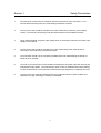
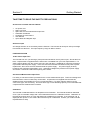
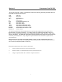
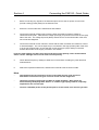
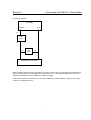
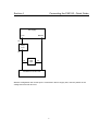
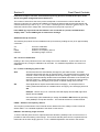
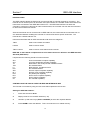
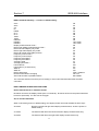
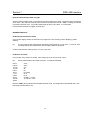
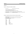
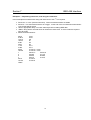
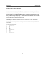
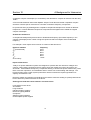
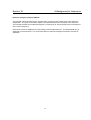
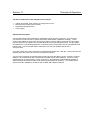
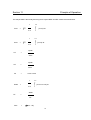
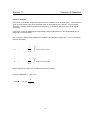
Contents
SECTION 1
SAFETY PRECAUTIONS ...........................................................2
SECTION 2
GETTING STARTED ..................................................................3
SECTION 3
OVERVIEW OF THE PA2100.....................................................5
SECTION 4
CONNECTING THE PA2100 - QUICK GUIDE ...........................6
SECTION 5
FRONT PANEL CONTROLS .....................................................9
SECTION 6
BACK PANEL CONNECTIONS ...............................................15
SECTION 7
IEEE-488 INTERFACE ............................................................16
SECTION 8
RS232 PORT ...........................................................................24
SECTION 9
PARALLEL INTERFACE..........................................................25
SECTION 10
A BACKGROUND TO HARMONICS .......................................26
SECTION 11
PRINCIPLE OF OPERATION ..................................................28
SECTION 12
CALIBRATION .........................................................................32
SECTION 13
FIRMWARE .............................................................................35
SECTION 14
OPTIONS.................................................................................36
SECTION 15
WARRANTY AND DISCLAIMER .............................................37
SECTION 16
SPECIFICATIONS ...................................................................38
SECTION 17
INDEX ......................................................................................40
1
Section 1
Safety Precautions
1
The PA2100 is constructed in accordance with the requirements of IEC 348 class I. This
ensures electrical safety when all normal safety precautions are taken.
2
The AC power cord should be inserted into a power outlet with a protective ground (earth)
contact. The PA2100 rear panel ground terminal should be used for additional safety.
3
Check that the applied AC power input voltage does not exceed the maximum AC power input
voltage of the PA2100.
4
The AC power cord should be inserted into a power outlet with ground contacts before
connections are made to the measurement inputs.
5
The instrument should only be opened by qualified personnel understanding the danger of
electrical shock hazards.
6
The outer cover should not be removed without isolating the AC power input and removing the
measurement input cables. The measurement input circuitry is isolated and therefore floating,
so care must be taken to ensure that the measurement input signals are completely removed.
6
The AC power input cable and measurement input cables should be in good condition and
replaced if any sign of damage or wearing is noticeable.
2
Section 2
Getting Started
TAKE TIME TO READ THE SAFETY PRECAUTIONS
Accessories included with the PA2100
•
•
•
•
•
•
•
AC power cord
Spare 1AT fuse
Spare 20A current measurement input fuse
Calibration Certificate
Certificate of Conformance
User Manual
Input cables and alligator clips
AC Power Input
AC voltage selection is not necessary with the PA2100. The PA2100 will accept an AC input voltage
from 90Vrms to 264Vrms. The input frequency range is 45Hz to 450Hz.
FUSE PROTECTION
1A AC Power Input Fuse
The PA2100 has 1AT (1A anti surge) fuse protection situated in the AC power input. Should the fuse
blow, a replacement is supplied with the instrument or available from your local representative. For
safety reasons always use the correct fuse type, size and rating. Additional AC input fuse protection
is provided inside the power supply. If the 1AT fuse blows and the PA2100 does not power up after
replacement, then check the fuse situated inside the power supply. The power supply is easily
located by the perforated metal safety cover. Hazardous voltages are present on this power supply
and section 1 should be read before opening the PA2100.
20A Current Measurement Input Fuse
For safety, a 20A internal fuse is provided for the current measurement input. This fuse is designed to
blow should the current continuously exceed 20A. A replacement is supplied with the PA2100,
additional fuses are available from your local representative. For safety reasons always use the
correct fuse type, size and rating. This fuse has a high current breaking capacity so it is advisable that
a replacement be obtained from Powertek.
Calibration
The PA2100 is calibrated before it is despatched from Powertek. The PA2100 should be calibrated
once a year to traceable voltage and current standards listed in the calibration section. Calibration of
the PA2100 requires entry of a four digit passcode available from Powertek. If the message ‘Cal’ is
displayed after power-on, this means the PA2100 may be uncalibrated. Contact your local Powertek
representative for help.
3
Section 2
Getting Started
Packaging
The PA2100 is a precision instrument and requires careful packaging to prevent damage during
transit. If the instrument has to be transported use the packaging materials provided by Powertek or
packaging materials of a similar quality. Ensure that the PA2100 is placed in a polythene bag before
packing to prevent ingress of moisture.
4
Section 3
Overview of the PA2100
The PA2100 AC Power Analyser is designed to measure the following electrical parameters with both
sinusoidal and distorted input signals.
Volts
Amps
Watts
VA
PF
Freq
VCF
ACF
THD V
THD A
HARM V
HARM A
INRUSH A
Volts rms
Amps rms
Real Power
Apparent Power
Power Factor
Fundamental Frequency Hz
Crest factor Volts
Crest factor Amps
Total Harmonic distortion Volts
Total Harmonic distortion Amps
Voltage harmonics orders 1 to 80
Current harmonics orders 1 to 80
Inrush Current
The above measurements are all determined from the PA2100 voltage and current inputs using
internationally recognised conventions. The voltage input is an isolated high impedance input of 1
Mohm. The current is measured using a fully isolated low impedance shunt, 0.02 ohms. Both inputs
are fully autoranging. The wideband inputs permit electrical measurement at high and low frequencies
as well as power frequencies. A high degree of input isolation allows connection anywhere in the
circuit under test.
Measurements are averaged to give stable readings. If there is a step change/trend in the input
voltage, current or frequency, the averaging will automatically disable to allow immediate observation
of the actual input signal amplitude or frequency.
Electrical measurements can be made in three ways:1
Viewing measurements from the front panel LEDs
2
Sending results to a standard printer via the parallel printer port
3
Using the optional IEEE-488 or RS232 computer interfaces
5
Section 4
Connecting the PA2100 - Quick Guide
1
Before connecting any signals to the PA2100 inputs connect the AC power cord, this will
provide a safety ground (earth) for the PA2100 case.
2
Ensure the circuit under test is switched off and isolated.
3
Connect the PA2100 voltage input across the load, the maximum working voltage is
1000Vrms/1440V peak. Note that the voltage input high (red) should connect to the live (line)
side of the load. The voltage input low (black) should connect to the neutral side of the load,
see connection diagrams.
4
Connect the PA2100 current channel in series with the load, remember the maximum current
is 20Arms/125Apk. The current input may be connected in the high (live/line) side of the load
or in the low (neutral) side. Ensure that the current input high (red) is always connected
towards the live/line of the supply, see later in this section.
Incorrect input polarity will affect only power and power factor polarity, other measurements
will be correct. Damage will not occur from incorrect polarity.
5
Check that the frequency reading is stable and correct before recording any other electrical
measurements.
6
Select the required measurement, and allow the PA2100 a few seconds to settle.
Hints
-
Check that electrical connections to the circuit under test are good and solid.
Intermittent connections will give incorrect results and are dangerous!
-
Use 4mm connecting plugs that are 18mm in length minimum. Best results are
achieved using 4mm plugs with "bunch" or "lantern" type spring contacts, especially
important for the current input.
-
Connect a standard printer to the parallel port to record results, this will save you time.
6
Section 4
Connecting the PA2100 - Quick Guide
Connection Diagram
AC Supply
AC Supply
Neutral
Neutral
³
Live
Live
³
Lo
PA2100
Amps
Input
Hi
Lo
PA2100
Volts
Input
Hi
Load/Device Under Test
Where possible use this wiring configuration. Here the current input is connected in the neutral supply
wire, note the position of the voltage and current Hi's and Lo's. The PA2100 voltage and current Hi
terminals should be connected towards the supply Live/High.
If the PA2100 Hi and Lo terminals are connected incorrectly, the watts reading is likely to be a minus
number, no damage will occur.
7
Section 4
Connecting the PA2100 - Quick Guide
AC Supply
AC Supply
Neutral
Live
³
Live
Neutral
³
Hi
PA2100
Amps
Input
Lo
Hi
PA2100
Volts
Input
Lo
Load/Device Under Test
With this configuration the current input is connected in the live supply wire, note the position of the
voltage and current Hi and Lo's.
8
Section 5
Front Panel Controls
Power
Power in watts is displayed continuously in the right hand display of the PA2100. True AC and DC
power is displayed along with plus or minus indications to show direction of power flow.
Vrms
True Rms voltage will be displayed in the function display. The displayed Rms includes both the AC
and DC component in the waveform. When selected the LED under the key will illuminate.
Arms
True Rms current in Amps will be displayed in the function display. The displayed Rms includes both
the AC and DC component in the waveform. When selected the LED under the button will illuminate.
VA
Selecting VA will display the product of Vrms and Arms. Often referred to as the maximum demand of
a system, required for rating purposes.
PF
Pressing PF, power factor, will display the true power factor over the range 0 to 1 using the definition
W/VA. Polarity indications + or – show whether the current is lagging or leading voltage.
+ = current leading voltage, capacitive
- = current lagging voltage, inductive
If the voltage and current are exactly in phase, then the polarity sign may alternate between plus and
minus.
The true power factor is valid where phase shift between fundamentals has occurred or when
harmonic distortion is present.
9
Section 5
Front Panel Controls
FREQ
Selecting frequency will display the fundamental or base frequency of the input signals. Frequency
can be detected from either the voltage or currents inputs. This is necessary if one of the input signals
is very distorted, ie. PWM signals. The default frequency source is the voltage channel. Always check
the frequency is stable and correct before recording a measurement.
Selecting the frequency source, V or A
The PA2100 can measure input frequency from either thhe voltage or current with the capability of
locking the frequency to 50Hz or 60Hz, explained next. Holding in FREQ for two seconds will display
whether the frequency is found from the voltage or current input or locked to 50Hz or 60Hz.
‘U’
‘A’
‘50’
‘60’
Frequency source is voltage
Frequency source is current
Frequency is locked at 50Hz
Frequency is locked at 60Hz
Press Vrms or Arms to select the required frequency source. Pressing frequency again returns the
user to frequency measurement.
Locking to 50Hz or 60Hz
These modes are used when the measured voltage and current waveforms are high frequency signals
modulated by the AC power frequency eg. 50Hz or 60Hz. To achieve stable measurement with these
conditions, all measurements have to be made over a complete number of cycles of the AC supply
frequency of 50Hz or 60Hz.
This mode is available by holding down the FREQ button for two seconds. Pressing 5 or 6 will select
50Hz or 60Hz mode. Pressing frequency again returns the user to frequency measurement. The
setting is saved and recalled at power on.
A typical application is measurement on the output of electronic lighting ballasts. Here the output
frequency could be 30kHz or more, modulated by a large 50Hz or 60Hz AC supply ripple component.
For stable measurement it is necessary to measure over a complete number of cycles of the
modulation frequency, eg. 50Hz or 60Hz.
CF
This function displays the crest factor of the input voltage or current waveform based on the ratio of
waveform peak/rms. After selecting CF the PA2100 will prompt V or A, press Vrms or Arms to select
voltage or current crest factor.
Crest factor allows the user to see if the waveform is deviating from a sinewave. The crest factor for a
pure sinewave is 1.41.
10
Section 5
Front Panel Controls
THD
Total Harmonic Distortion THD displays the percentage ratio of the harmonic rms and noise of the
fundamental rms. After selecting THD the PA2100 will prompt V or A, press Vrms or Arms to select
voltage or current THD. The LED under the key will light. The THD range using the front panel
display is 3% to 999%.
Pure THD (harmonic rms/fundamental rms as a percentage) is available using the PA2100 with a
printer. The THD shown at the end of the printout is then calculated from each of the listed hamonics.
Greater THD accuracy is achieved if more harmonics are included in the THD calculation, see the next
section describing the harmonic analysis capability of the PA2100.
The THD range using the PA2100 with a printer is 0.1% to 999%.
HARM
Pressing HARM allows access to the voltage and current harmonic analysis. After selecting HARM,
the PA2100 will prompt V or A. Voltage or current harmonic analysis can be selected, press the Vrms
button to select voltage harmonics or Arms for current harmonics. After the selection has been made,
H1 will be displayed in the right hand display, the Harm led will light along with the led under the Vrms
or Arms key.
It is possible to increment through the harmonics using the up/down keys marked with an arrow (eg
THD and Inrush). Use these keys to increment to the desired harmonic. Keeping the key pressed will
cause the PA2100 to increment quickly through the harmonics. The harmonic number (H1 to H50) is
displayed in the right hand display. The harmonic amplitude is displayed in the left hand display.
Harmonics H2 to H50 are displayed as a percentage of the fundamental rms. The fundamental H1, is
displayed in actual volts or amps rms.
Printing Harmonics
Pressing Print will send the voltage and current harmonics to the parallel printer port. The number of
harmonics sent to the printer will depend on the harmonic number selected. For example, if harmonic
9 is selected and print is pressed, the PA2100 will print the odd voltage and current harmonics up to
th
the 9 eg. 1, 3, 5, 7, and 9. Selecting an even harmonic number, say 14, will send both odd and even
th
voltage and current harmonics to the printer up to the 14 .
To exit harmonic analysis press HARM, the PA2100 will return to Vrms.
See section on Harmonic Analysis for more information.
11
Section 5
Front Panel Controls
INRUSH
Selecting INRUSH will store and display the largest current peak and is used typically to measure the
inrush or starting current of a load at switch on. All inrush events lasting 15uS or longer are
measured. It is possible to clear the peak reading by pressing INRUSH again.
To ensure that the peak current is captured with short duration (>600uS) inrush current events, it is
possible to select the starting current range. This ensures that the peak current is captured and not
missed due to the autoranging process.
The current ranges of the PA2100 are:
Range
Peak Amps
1
2
3
4
5
6
7
8
0.3A
0.6A
1.8A
3.6A
10.7A
21.3A
62.5A
125.0A
Pressing the INRUSH current key and holding in for 2 seconds will display the starting range. Use the
up and down keys marked with an arrow (THD and Inrush) to select the desired current range. Press
HARM to accept the range, the PA2100 is now ready to capture the inrush current.
Switch the load on and observe the peak current reading. It is advisable to switch off and repeat the
test several times. Where applicable, always allow the circuit under test time to discharge before
repeating the inrush current test.
PRINT
PRINT is used to print results by sending the measurements to the Parallel Centronics port. All
printed results are true simultaneous measurements.
The standard printout consists of the following parameters:Vrms
Arms
VA
PF
Watts
Hz (Volts, Amps, 50Hz or 60Hz)
CF V
CF A
THD V
THD A
12
Section 5
Front Panel Controls
If harmonic analysis has been selected before pressing printout, the PA2100 will print all the
above along with voltage and current harmonics.
The number of harmonics sent to the printer will depend on the harmonic number selected. For
example, if harmonic 9 is selected and PRINT is pressed, the PA2100 will print the odd voltage and
th
current harmonics up to the 9 eg. 1, 3, 5, 7 and 9. Selecting an even harmonic number, say 14, will
th
send both odd and even voltage and current harmonics to the printer up to the 14 .
If the PRINT key is pressed and the PA2100 is not connected to a printer, the PA2100 will
display ‘Hold’. Press PRINT again to remove this message.
Additional Set-up Functions
The following keys allow access to additional set-up functions by holding the key in for approximately
2 seconds:VA
PF
FREQ
INRUSH
-
Access to calibration
Control of averaging
Selection of Frequency Source
Set starting range of Inrush
VA – Access to Calibration
Holding in the VA key allows access to the voltage and current calibration. A pass code has to be
entered before any change to calibration can be made. For a detailed explanation see section on
Calibration.
PF – Control of Averaging, Auto or Set
Auto
All measurements are automatically averaged to give stable results. Automatic
averaging will average the last 16 measurements. One measurement is typically 0.75
seconds. If there is a step change/trend in the input voltage, current or frequency, the
averaging will automatically disable to allow immediate observation of the actual input
signal or frequency. Stable results and a fast response to change is achieved using
auto averaging. Auto averaging is the power on default setting of the PA2100.
Set
Some applications require fixed measurement averaging. An example of this is
making measurements with an unstable load or AC supply, here averaging has to be
Set.
Example: Hold PF key in for 2 seconds, left hand display will show AV, right hand
display will show AUto.
Use select keys (THD & INRUSH) to change from AUto to SEt followed by pressing
enter (HARM) to accept the selection. The PA2100 will return to measurements.
FREQ – Selection of Frequency Source
The frequency measurement of the PA2100 can be obtained from the voltage, current or fixed at
50Hzor 60Hz. For a detailed explanation see earlier in this section.
INRUSH – Set starting range of Inrush
To ensure that the peak current is captured with short duration (<600uS) inrush current events, it is
possible to select the starting current range. This ensures that the peak current is captured and not
missed due to the auto ranging process. For a 13detailed explanation see earlier in this section.
14
Section 6
Back Panel Connections
AC Power Input, On/off Switch and 1AT (Anti Surge) Fuse
The AC power input is a combined AC input connector, noise rejection filter, on/off switch and fuse
holder (rating 1A).
Optional IEEE-488 Connector
This connector permits connection of the PA2100 to an IEEE-488 interface bus. Full talk and listen
facilities are implemented.
Parallel Centronics Printer, 25 pin D type connector
Connection to any parallel input printer is possible using this standard parallel output port.
Optional RS232
This connector is a 9 pin D type connector. BI directional RS232 serial communication using a data
rate of 9600 baud is possible using this port.
15
Section 7
IEEE-488 Interface
INTRODUCTION
The IEEE Interface allows the PA2100 to communicate with a controller (typically a computer). The
PA2100 can be used as part of an automatic test system where the controller sends commands to the
instruments connected to the IEEE-488 interface bus. The IEEE-488 interface bus allows the
controller to instruct an instrument to make measurements, the controller can then ask the instrument
to return the measurement results.
Several instruments can be connected to an IEEE-488 bus, this means that each instrument has it’s
own dedicated address enabling the controller to communicate with a specific instrument. The
PA2100 has a default address of 9.
Instruments with fitted with an IEEE-488 interface fall into three categories:Talker
Able to send results and status
Listener
Able to receive results
Talker-Listener
Able to receive commands and send results
IEEE-488 on the PA2100 is implemented as a full talker-listener as defined in the IEEE Standard
488-1978 (IEEE-488.1).
It implements the following interface functional subset:
SH1
AH1
T6
TE0
L4
LE0
SR1
RL1
PP0
DC1
DT0
C0
Source handshake complete capability
Acceptor handshake complete capability
Basic talker, with serial poll and unaddress if MLA
No extended talker
Basic listener, unaddress if MTA
No extended listener
Service request complete capability
Remote-Local complete capability
No parallel poll capability
Device clear complete capability
Device trigger capability
No controller capability
CONTROLLING THE PA2100 OVER THE IEEE-488 INTERFACE BUS
The PA2100 is controlled by using the text commands explained in this section.
Setting the IEEE-488 address:
1.
Press and hold down Arms
2.
Display will show current IEEE address (1-30)
3.
Use SEL up and down keys (THD and INRUSH) to select the required address.
4.
Press HARM to enter the address. This is now stored in non-volatile memory.
16
Section 7
IEEE-488 Interface
IEEE Command Summary, * = Power-on default setting
Vrms
Arms
VA
PF
FREQ
CF V
CF A
THDV
THDA
INRUSH
HARM V
HARM A
Display measurements mode *
Return both display measurements mode *
Return left hand display only mode
Return right hand display only mode
Return all results mode (li8ke printout)
Frequency source Volts *
Frequency source Amps
Frequency fixed 50Hz
Frequency fixed 60Hz
Averaging fixed
Averaging automatic *
Fast mode off *
Fast mode on (no harmonics)
SRQ on
SRQ off *
Return status byte
Resets measurement averaging
Send 8 bit number to parallel interface
D0
D1
D2
D3
D4
D5
D6
D7
D8
D9
HV1-HV50
HA1-HA50
R0
X0
X1
X2
R1
FV
FA
F5
F6
A1
A0
M0
M1
Q1
Q0
Spoll + address
A0 or A1
B0 to B255
The controller should use an EOI (end or identify) or send a line feed terminator after the IEEE
command.
IEEE COMMAND STRING EXPLANATIONS
Return measurements in mode R0 and R1
R0 allows access to the display results (see X commands). R1 allows access to the printout data and
hamonics (all results). R1 also acts as a trigger.
X0, X1 and X2 commands
When in R0 mode (power on default setting), the display results are made available in three ways:X0 mode
Returns both left and right hand display measurements, X0 is the power-on
default setting.
X1 mode
The PA2100 will return the left and function display measurements only.
X2 mode
The PA2100 will return the right hand display measurement only.
17
Section 7
IEEE-488 Interface
D (display) Commands
The D command allows the controller to select which measurement is shown on the PA2100 function
display.
Vrms
Arms
VA
PF
FREQ
CF V
CF A
THD V + noise
THD A + noise
INRUSH
D0
D1
D2
D3
D4
D5
D6
D7
D8
D9
This command is equivalent to pressing a function select key when the instrument is being used
manually. In R0 mode, the PA2100 will return the measurement that has been selected using the D
commands.
Selecting Harmonic Measurements
The HV and HA commands allows the controller to select which harmonic measurement is displayed.
The instrument will then calculate both volts and amps harmonics up to the number selected. If an
odd number is selected, only odd harmonics will be returned. If an even number is selected, then all
harmonics up to the number selected will be returned.
HARM V
HARM A
HV1-HV50
HA1-HA50
Setting Frequency Source
Frequency Volts
Frequency Amps
Frequency fixed 50Hz
Frequency fixed 60Hz
FV
FA
F5
F6
These settings will not change the current frequency source selection stored in non-volatile memory.
IEEE Fast Mode M1
Enabling IEEE fast mode increases the rate at which the PA2100 will return measurements.
Harmonics, fundamentals, PF ± sign and THD are not available in fast mode. Typically 3
readings/second.
Averaging
Averaging fixed
Averaging automatic
A1
A0
Sending these commands will also reset measurement averaging.
18
Section 7
IEEE-488 Interface
Reset Averaging
Resets measurement averaging
see A command
Service Request
SRQ on
SRQ off
Q1
Q0
Status Byte Serial Poll
Return status byte
Spoll xx
xx = PA2100 IEEE address
Bit 0
complete)
Bit 6
Bit 7
Averaging complete (logic 1 when averaging
SRQ bit (logic 1 is set when service is requested)
Data ready (logic 1 when data ready)
IEEE-488 Control of Parallel Port
Sends an 8 bit number (B0 to B255) to parallel interface
Eg
sending B255 will send 11111111 to the parallel interface
Sending B3 will send 00000011 to the parallel interface
READING RESULTS
Return display measurements R0
In this mode, the PA2100 is configured to return display measurements when read. This is the default
setting. In this mode an IEEE read will return a single line consisting of the two display
measurements. This mode cannot be used for harmonic measurements (see R1 command).
Selecting the Inrush function will automatically return to the R0 mode.
Return all results mode R1
In this mode, the PA2100 will return all the measurement results usually obtained on the printout.
Voltage harmonics and current harmonics will be included if the harmonic function has been
previously selected. The number of harmonics sent will depend on the harmonic number selected.
The R1 command acts as a trigger. At the end of the next measurement cycle following R1, the
results will be sent to the IEEE output buffer ready to be read.
Measurements will not be available until one measurement cycle following the R1 command.
19
Section 7
IEEE-488 Interface
Returned measurement data using R1
All the results normally found on the printout are stored ready to be read. An IEEE read is required for
each result. After the last result ha been read the instrument will send an ‘*END*’ message to indicate
all results have been sent. Any further IEEE reads ill return a line feed. To read further
measurements another R1 trigger must be sent.
READING RESULTS
R0 Display measurements mode
In this mode display results are returned on a single line in the format [function display] + [watts
display].
Eg
if Vrms is the function selected the data string returned will be ‘x.xxxx Vrms +x.xxxx W’, 0ah
all strings will be terminated with a line feed (0ah) and EOI will be set.
Inrush measurements will only return ‘±x.xxxx A pk’, 0ah.
R1 Return all results
In this mode many results are stored, each string has to be read a line at a time.
Eg
236.5
0.0613
14.512
+8.434
0.581
49.97
1.412
4.260
00.92
158.58
*END*
Eleven IEEE reads would need to be sent. To read the following:
Vrms
Arms
VA
W
PF
Hz (volts)
CF V
CF A
%THD V + noise
% THD A + noise
Note the *END* string indicates that all data has been read. All strings will be terminated with a line
feed (0ah) and EOI will be set.
20
Section 7
IEEE-488 Interface
EXAMPLES
Example A – Reading Volts and Watts with R0 Mode
!
Send ‘R0, d0’
Sets R0 mode and Vrms function
Note: Upper and lower case can both be used
Separate commands by comma or space
R0 mode will stay selected until the R1 command is received
!
!
!
Wait until reading is available by inserting a delay or by reading the status byte
Send IEEE read
PA2100 will return a string containing Vrms and Watts results
Further IEEE reads will return the PA2100’s current result
Example B – Requesting all results (no harmonics) using the R1 command
!
!
!
!
!
Ensure that the PA2100 is not in harmonic or inrush mode (send any D command)
Send R1 (trigger)
Use an appropriate delay or monitor status byte before reading IEEE data
Send IEEE reads until *END* is received
Returned measurements:236.5
0.0613
14.497
8.423
0.581
49.97
1.412
4.260
00.92
158.58
*END*
Vrms
Arms
VA
Watts
PF
Hz (volts)
CF V
CF A
%THD V + noise
%THD A + noise
21
Section 7
IEEE-488 Interface
Example C – Requesting harmonics, and using R1 command:th
In this example all measurements along with harmonics to the 7 are required.
!
!
!
!
!
Send ‘HV7’ or ‘HA7’ (selects harmonics). Wait until measurements are stable
Send ‘R1’ This sets mode and acts as a trigger. At the end of the next PA2100 measurement
cycle results will be stored
Use an appropriate delay or monitor status byte before reading IEEE data
‘*END*’ string will be received when all results have been read. If more results are required
send R1 again
Returned measurements:236.5
0.0613
14.512
+8.434
0.581
49.97
1.412
4.260
00.92
158.58
1
3
5
7
00.79
107.90
*END*
Vrms
Arms
VA
W
PF
Hz
CF V
CF A
%THD V + noise
%THD A + noise
236.40 V
0.0327 A
00.49%
70.17%
00.54%
63.96%
00.31%
51.27%
%THD V
%THD A
22
Section 7
IEEE-488 Interface
HINTS FOR READING BACK DATA
AFTER DATA DROM THE PA2100 HAS BEEN READ, THERE IS A DELAY BEFORE THE IEEE
OUTPUT BUFFER IS UPDATED. DURING THIS TIME THE PA2100 WILL RETURN A LINE FEED
IF THE CONTROLLER SENDS AN IEEE READ BEFORE THE PA2100 IEEE OUTPUT BUFFER IS
UPDATED.
Depending on the harmonic number selected, the PA2100 can take several seconds after
receiving a trigger (R1) to complete all the measurements.
Before reading the data, monitor the status byte or insert a delay before sending IEEE reads.
When calculating a delay, use 0.25 seconds for each harmonic. Eg. 50 harmonics will take about
12.5 seconds before data is ready.
23
Section 8
RS232 Port
NOTES FOR USE OF PA2100 RS232 PORT
To control the PA2100 through the RS232 port, use the command set as detailed in the IEEE-488
User Manual. These commands are valid for IEEE and RS232 control. The exceptions are the Q1
and Q0 commands, which are IEEE specific.
An extra command ‘c1’ is provided for the RS232. This is a command to tell the instrument to send
data. To read data from the PA2100 send ‘c1’ and then read from the RS232 port. The end of data
sent by the PA2100 is signified by the byte 1a Hex.
The baud rate is fixed at 9600 for transmit and receive
To program the PC RS232 port use 8 data bits and two stop bits, and no parity. Use hardware
handshaking.
The 9 way plug on the rear panel has a standard pinout and will connect to a PC by a standard null
modem cable.
The 9 way connector pins are:
1.
2.
3.
4.
5.
6.
7.
8.
9.
Not Connected
Rx
Tx
CTS
0V
Not Connected
RTS
CTS
Not Connected
24
Section 9
Parallel Interface
Parallel Port
The parallel printer output allows the user to send all the PA2100 measurements directly to a printer
fitted with a Parallel Centronics input. A standard PC type parallel printer cable (25 pin "D" to
Centronics) is required to connect the PA2100 to a printer. The data is sent to the parallel port when
the PRINT button is pressed.
If the print key is pressed and the PA2100 is not connected to a printer, the PA2100 will display
‘Hold’, Press PRINT again to remove this message.
Read the relevant part of section 5 which describes the PRINT key operation.
25
Section 10
A Background to Harmonics
A repetitive complex waveshape (not a sinewave) was deemed too complex to describe until the early
1800’s.
A French mathematician called Jean Baptiste Joseph Fourier discovered that a repetitive complex
waveform could be split or resolved into a number of sinewave frequency components.
He proved his theory by breaking down a repetitive complex waveshape into a number of different
frequencies. He then added the frequencies components back together and created the original
complex waveshape.
So what are harmonics?
A complex waveshape always has a base or fundamental frequency (the lowest frequency in the
complex waveshape) and a number of higher frequencies that are multiples of the fundamental
frequency.
For example a 1kHz square wave is known to consist of odd harmonics:Harmonic Number
st
1 (Fundamental)
rd
3
th
5
th
7
th
9
th
11
etc to infinity
Frequency
1kHz
3kHz
5kHz
7kHz
9kHz
11kHz
Impact of Harmonics
Today’s AC power distribution system was designed to operate with near sinewave voltages and
currents. Many loads connected to the AC supply cause the voltage and current to become nonsinusoidal. These additional frequency components flowing in devices like power transformers, power
factor correction capacitors, circuit breakers and AC motors can cause heating and damage. The
harmonics also cause a lower system power factor which increases the required generation VA
capacity and therefore cost.
Electricity utilities and equipment manufacturers around the world are seeking to quantify and limit the
level of harmonic pollution because of the above.
Some typical loads that cause harmonic currents to flow
Large AC/DC motor drives
Arc welders
Large rectifiers
Induction heating systems
Electronic lighting ballasts
Computers
Switching power supplies
Uninterruptible power supplies
26
Section 10
A Background to Harmonics
Harmonic Analysis using the PA2100
The PA2100 uses a Discrete Fourier Analysis (DFT) to measure the voltage and current harmonic
magnitudes. This gives an excellent rejection of unwanted frequencies contained in the waveform.
The PA2100 will track the fundamental frequency continuously to ensure the harmonics are analysed
at the correct frequency.
Harmonics 2 to 50 are displayed as a percentage of the fundamental rms. The fundamental (H1) is
displayed in Vrms and Arms. For more information on Harmonic Analysis see section ‘Principle of
Operation’.
27
Section 11
Principle of Operation
The main components of the PA2100 Power Analyser
•
•
•
•
Analog input board, input sections for voltage and current.
Main processor board (mother board)
Keyboard and display board
Power supply
Operational Description
The PA2100 analog board attenuates or amplifies the input signals as required. A current shunt
converts the input current into a voltage that is then attenuated or amplified accordingly. These
analog input signals are then fed to an analog to digital convertor (ADC) converting the input signal
into 8 bit numbers, the sample rate selected depends on the input signal frequency. All gain stages
and attenuation on the analog boards are controlled by the microprocessor via an opto isolated serial
interface link. The 8 bit sample data is transferred over the opto isolation barrier to the
microprocessor.
The input voltage and current waveforms are digitized simultaneously. Both the V and A channels are
isolated (3kV) with respect to each other and ground (chassis).
The processor averages the measurement results and sends the data to the two 4.5 digit 7 segment
displays. All measurements are automatically averaged to give stable readings. If there is a step
change/trend in the input voltage, current or frequency, the averaging will automatically disable to
allow immediate observation of the actual input signal amplitude or frequency. The measurement
results are made available to the Printer port or IEEE-488 / RS232 interfaces.
28
Section 11
Principle of Operation
The sample data is then analysed using the accepted IEEE and IEC measurement definitions.
Vrms
Arms
√
=
√
=
2πn
1
∫
(V inst)² dt
2πn
0
1
2πn
∫
2πn
(A inst)² dt
0
Vpeak
Vcf
=
Vrms
Apeak
Acf
=
Arms
VA
=
Vrms x Arms
1
Watts
2πn
∫
=
2πn
(V inst x A inst) dt
0
Watts
PF
=
VA
VArs
=
√ (VA² - W²)
29
Section 11
Principle of Operation
Harmonic Analysis
Harmonics are analysed using a technique known as Discrete Fourier Analysis (DFT). This technique
gives accurate results even when significant noise at other frequencies is present. The PA Series
Analysers constantly track the fundamental frequency, so this allows all harmonics to be analysed
accurately.
Harmonics 2 to 50 are displayed as a percentage of the fundamental rms. The fundamental (H1) is
displayed in Vrms and Arms.
The "a" and "b" values below represent the inphase and quadrature components. "Func t" represents
the input waveform.
2πn
1
a
=
2πn
(Func t x sin nωt) dt
0
2πn
1
b
∫
∫
=
2πn
(Func t x cos nωt) dt
0
Both magnitude and angle are calculated using these formulae:
Harmonic Magnitude = √ (a² + b²)
b
Angle θ
= arc tan
a
30
Section 11
Principle of Operation
Total Harmonic Distortion - THD
Two types of formulae are available to analyse THD:THD Range 0.1% to 999.9%, calculated from the harmonics and included at the end of the printout:-
THDV =
√ (VH2%² + VH3%²
THDA =
√ (AH2%² + AH3%² + ……..AH50%²)
+ ……..VH50%²)
Mathematically equivalent to
√
(VH2² + VH3² + ……..VH50²)
THDV =
x 100%
VH1
√
(AH2² + AH3² + ……..AH50²)
THDA =
x 100%
AH1
THD + noise range 3% to 999.9% using front panel display
√
(Vrms² - VH1²)
THDV + noise =
x 100%
VH1
√
(Arms² - AH1²)
THDA + noise =
x 100%
AH1
THD + noise will take account of any DC or noise contributions present in the waveform. The
calculation time of THD + noise is much shorter than THD. THD + noise will often give a larger
number than the THD.
31
Section 12
Calibration
PA2100 Calibration Procedure
Introduction
Calibration of the PA2100 voltage and current inputs is performed by applying a traceable reference
level to each voltage and current range. The actual PA2100 reading and reference are then
compared, the calibration constants are then calculated. This means that calibration of the PA2100
does not require adjustment of trim potentiometers or even the removal of the outer case.
Equipment Required
Voltage calibration source ±0.02% accuracy or better
Range 1Vrms to 500Vrms 50Hz or 60Hz.
Current calibration source ±0.02% accuracy or better
Range 0.12Arms to 20Arms 50Hz or 60Hz.
Alternatively a stable voltage and current source may be used in conjunction with a high accuracy AC
voltmeter and current shunt. The voltmeter and current shunt are used to measure the applied voltage
and current.
Calibration of the PA2100 voltage and current inputs is all that is necessary. All other PA2100
measurement parameters are calculated from the voltage and current inputs.
Before Calibrating a PA2100
1.
A warm-up period of 30 minutes is allowed before measurements are taken.
2.
Allow a 10 second settling time is allowed before recording a measurement.
3.
The calibration signal ground (low) is connected to the low terminal (Black) of the PA2100
4.
All instrument accuracy specifications are valid for a 1 year period.
5.
Room temperature = 23°C ± 2°C.
32
Section 12
Calibration
Calibration Procedure
Allow at least 30 minutes warm up.
The following two tables show the voltage and current ranges and the applied calibration levels:-
Range
Number
Voltage range
Volts Peak
Applied calibration level
Voltage rms
8
7
6
5
4
3
2
1
1440.0
720.0
220.0
110.0
33.0
16.0
5.0
2.5
500.0
250.0
120.0
60.00
20.00
10.00
2.400
1.200
Range
Number
Current range
Amps Peak
Applied calibration level
Amps rms
8
7
6
5
4
3
2
1
125.0
62.5
21.3
11.0
3.6
1.8
0.6
0.3
16.0
16.0
10.0
5.0
2.0
1.0
0.24
0.12
If a mistake is made during any stage of the calibration, just switch off and start again. The previous
calibration will remain intact. A new calibration is stored when ‘SAVE’ is selected.
33
Section 12
Calibration
1.
To enter calibration mode hold down the VA button for approximately 2 seconds. The left
hand display will show ‘Code’, the right hand display will show ‘----‘.
2.
Enter the calibration code 1508. Use the numbers under the keys.
3.
Left hand display will show ‘CAL’, right hand display will show ‘V’ or ‘A’.
4.
Select V (Voltage calibration) by pressing Vrms. (If current calibration is required then select
Arms).
5.
‘Vr1’ will be displayed in the right hand display, ‘CAL’ will remain in the left hand display.
At this point it is possible to increment up and down to other ranges using the THD (up) and
INRUSH (down) keys.
If a full calibration is required start with voltage range 1 (Vr1).
6.
Apply the recommended voltage, see the voltage calibration table.
7.
Press the HARM key (enter) to begin calibration.
8.
The actual voltage reading will be displayed in the left hand display. When the PA2100
averaging is complete, the left hand voltage display will stop updating and ‘----‘ will appear in
the right hand display. A four digit calibration constant has to be calculated and entered:-
Applied voltage
The calibration constant =
x 2048
PA2100 reading
9.
Enter the 4 digit calibration constant, the PA2100 will automatically accept this number.
Range 1 is now calibrated. ‘Vr2’ is now displayed in the right hand display. If a mistake is
made enter any number then return to the range using the up/down keys and recalibrate
starting from step 5.
10.
Select the voltage input level required for range 2 (Vr2). Repeat steps 5 to 9 for ranges 2 to 8
until ‘SAVE’ is displayed.
11.
The calibration constants can now be stored. The PA2100 will show ‘SAVE’ in the right hand
display after calibration of range 8, press HARM (enter) to save the calibration.
12.
Check each voltage (or current) range by applying a traceable reference level to ensure that
the PA2100 meets its specification.
13.
To calibrate current start from step 1 and enter ‘Arms’ instead of ‘Vrms’ at step 4. Apply the
current calibration levels shown before the procedure and repeat steps 5 to 12.
14.
If you check the current with no voltage applied, do not forget to set the frequency source to
‘Amps’.
34
Section 13
Firmware
Introduction
Powertek has an on going firmware development for all its products. At regular intervals new features
and upgrades are made available.
Firmware up-grades are possible by the replacement of an EPROM situated on the main board. It is
the only IC with a version number label. Updates are available from your local representative or from
Powertek Ltd.
The EPROM can be replaced easily:
1.
Switch off, remove AC power cable and all measurement input connections, read safety
section 1.
2.
Unscrew and lift off the top cover.
3.
Locate the EPROM identifiable by the version number label.
4.
Using anti-static precautions, remove the EPROM using an extractor tool to avoid damage to
the EPROM or PCB.
5.
Carefully insert the new EPROM, check all internal cables are secure and reassemble the
PA2100.
6.
Power up the PA2100 and check that the new version number is displayed at switch on.
7.
Check that the PA2100 is working by applying a known input voltage and current.
Replacement of the EPROM will not affect calibration
35
Section 14
Option 03
Option 04
Option 05
Option 05A
Option 06
Option 09
Option 10
Option 13
Option 24
Option 25
Option 28
Option 28A
Option 49
Option 61
Option 65
Option 65A
Option 65B
Options
500Arms 100:1 Current Transducer
1200Arms 1000:1 Current Transducer
IEEE-488 Interface
RS232 Interface
PA Series Printer Cable
PA2100 Rack Mounting Kit
IEEE-488 Cable 2 Metre
PA2100 UKAS Certificate
Rear Panel Inputs
HV 40kVpk 2000:1 Probe
Additional 1m Test Lead Set
Additional 3m Test Lead Set
1250A/125A:1A Toroid Current Transformer ±0.2%
PA2100 Hard Flight Case
DPU-414 Seiko Thermal Printer
20 rolls of paper for option 65
Battery pack for DPU-414 Seiko Thermal Printer
SAFETY WITH CURRENT TRANSFORMERS
Always connect the current transformer to the PA2100 current input before attempting to clamp
around the current carrying conductor. As with any clamp-on current transducers, care must be taken
to ensure that the clamp is securely closed before use. Periodically the clamp magnetic surfaces
should be inspected and cleaned as required. An air gap in the magnetic circuit will result in large
amplitude and phase shift errors.
36
Section 15
Warranty and Disclaimer
The PA2100 is warranted against defects in materials and workmanship for a one year period.
Powertek reserves the right to decide if the repair is under warranty. This will not apply to defects
resulting from misuse or unauthorised modifications. Powertek cannot accept legal liabilities for any
inaccuracies in this documentation. Powertek reserves the right to alter the specification without
notice.
37
Section 16
Measurement
Bandwidth
VOLTS
Display Resolution
Specifications
DC, 5Hz to 250kHz
4 ½ digit
Measurement range
700mVrms to 1000V rms (1440Vpk)
(200mVrms with blanking disabled)
Max input volts
1000Vrms (1440Vpk) Overload: 3000Vrms for 1 second
Max input CF
20
Accuracy
±0.2% Rdg ±0.2% Range
± 0.02% per kHz ±10mV
Common mode V
rejection
90dB
(1 kHz @ 100V with 1 kΩ Imbalance)
Input Impedance
1 MΩ 12pF
CURRENT
Display Resolution
4 ½ digit
Measurement range
0.0144Apk to 125.00Apk
600Arms with Option 03, 1200Arms with Option 04
Max input Amps
20Arms (125Apk) Overload: 500Arms for 1 second
Max input CF
20
Accuracy
±0.2% Rdg ±0.2% Range
±0.02% per kHz ±2mA
Common mode V
Rejection
< 10mA
(1 kHz @ 100V applied to Hi and Lo terminals)
Input Impedance
0.020Ω
POWER
W
W
VA
45-65Hz
±0.4% Rdg ±0.2% range ± 2mW
±(0.02/PF)% per kHz
±0.2% Rdg ±0.1% range
±0.4% Rdg ±0.2% range
38
Section 16
Specifications
POWER FACTOR
Range
Capacitive load
Inductive load
0.000 to ±1.000
+ = Leading PF
- = Lagging PF
Accuracy
±0.002 ±0.0005/PF per kHz
CREST FACTOR
Range
Accuracy
1 to 20
±0.002
INRUSH CURRENT
Range
0.1Apk to 125Apk
Up to 1200Apk with Option 04
Accuracy
±1.5%
Frequency
Range
5Hz to 125kHz
Accuracy
±0.1% of reading
HARMONIC ANALYSIS
Range
Fund Accuracy
Harm Accuracy
DC, Fund to 50
±0.2% Rdg ±0.2% Range
±(0.1 + 0.02 per kHz)%
THD
Range
Accuracy
0.1% to 999.9%, Via display 2% to 999.9%
±0.3% ± 0.01% per kHz
th
INTERFACES
Standard: Parallel Centronics Printer port
Options: 05 - IEEE-488
Options: 05A - RS232
ENVIRONMENT
Operating Temperature 0°C to +50°C
Storage Temperature -40°C to +60°C
Humidity 10%-90% RH non-condensing
DIELECTRIC STRENGTH
Inputs to case 3kV AC 50/60Hz for 1 minute
AC line input to case 2kV AC 50/60Hz for 1 minute
POWER INPUT
AC line input range 90Vrms to 264Vrms AC
AC line input frequency 45Hz to 450Hz
AC line input fuse protection 20mm 1AT (anti surge)
Power consumption 16W 30VA
DIMENSIONS
Width 215mm x Height 144mm x Depth 390mm
WEIGHT
5.5 kg
(6kg boxed)
39
Section 17
A
Index
Frequency Source, 10, 13
Front Panel Keys, 9
Fuse Protection, 3
AC Power Input, 3, 14
Accessories, 3
Arms, 9
B
RS232, 14, 23
H
HARM Harmonics, 11
Harmonic Analysis, 25, 29
Back Panel Connections, 14
C
Calibration, 3, 31, 32
CF Crest Factors, 10
Connecting the PA2100, 6
Connection Diagram, 7
Control of averaging, 13
Current Transformers, 35
F
S
Safety Precautions, 2
Specification, 37
I
IEEE-488, 14, 15
IEEE-488 Commands, 16
INRUSH, 12
Inrush Range, 13
T
THD, 11, 30
V
O
Options, 35
E
EPROM, replacement of, 34
R
P
PF Power Factor, 9
Principle of Operation, 27
PRINT, 12
Printer port, 14, 24
Firmware, 34
FREQ, 10
March 2003
40
VA, 9
Vrms, 9
W
Watts Calculation, 28