1
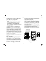
TVR10/100/1000TM
TRACE VERIFY REPAIR
LAN TESTER
●
© 2005 Byte Brothers, Inc.
www.bytebrothers.
Network Test and Certification
7003 132nd Place SE, Newcastle, WA 98059 USA
+1.425.917.8380 ● FAX +1.425.917.8379 ● [email protected]
●
Table of Contents
Limited Warranty
The manufacturer warrants to the original consumer that this product is
in good working order for a period of one year from the date of purchase.
During this period the product will be repaired or replaced without charge
for either parts or labor. Repair or replacement as provided under this
warranty is the exclusive remedy of the purchaser.
Made in the USA. Copyright 2005.
TVR10/100/1000, TVR1000 , TVR and Test, Verify and Repair are
trademarks of Byte Brothers, Inc.
Model TVR10/100/1000 User's Guide
Free DVD
The TVR1000's big brother, the Real World Certifier, has a DVD describing its use. The DVD includes a clip of the TVR1000 in action. If
you would like a copy of this DVD, please call 800.999.2983 or email
[email protected].
Section I. Introduction ........................................................
The 10 Most Common Questions answered
TVR10/100/1000 List of functions
Section II. The Three phases of LAN installation .............
Section III. Faceplate description ......................................
Section IV Learning the Main Unit's Faceplate ................
10/100/1000 LAN Test jacks and LEDs
Single port testing
Inline testing
Cable Test Jack and LEDs / Remote Probe
Section V. Learning the Remote Probe's Faceplate .......
Section VI. Performing LAN Tests ....................................
Test example #1. Testing a PC or hub/switch to verify
the device type, speed and duplex (single port test).
Test example #2. Cabling a PC to a switch (Inline test).
Test example #3. Testing a switch or PC at the far
end of a cable for activity (using the Main Unit’s
10/100/1000 LAN tests section).
Test example #4. Testing a switch or PC at the far
end of a cable for continuity (using the Main Unit’s
Cable Tests section).
Test example #5. Tracing a cable's location ("toning")
to a wiring closet (or to a switch port).
Test example #6. Testing a cable’s pair configuration.
Appendix A. Wiring primer ................................................
Appendix B. 10, 100 and 1000 Base-T Basics .................
Appendix C. Ways to Minimize LAN Problems ...............
Appendix D. Self-test and battery replacement ...............
2
6
8
10
17
20
33
39
43
44
Section I. Introduction.
Negotiation makes networks work. Twisted pair cable is the
standard for local area networks (LANs). Its popularity stems from its
ease of use, cost, speed and maybe most importantly, adaptability.
A 10 Base-T device installed years ago communicates with a new
gigabit switch (1000 Base-T) because the standard that defines
LAN Ethernet communications requires devices negotiate to find a
common speed and duplex. For instance, if the devices are working
correctly, a 100 Base-T, half duplex PC connected to a 1000 Base-T,
full duplex switch will force the switch to negotiate "down" to 100
Base-T, half duplex mode. You can verify this by connecting the
TVR1000 "inline" between the two devices and displaying the link's
negotiated speed and duplex. The inline capability is remarkable and
only available on other testers that cost over 7 times the price of the
TVR1000. The TVR1000 also performs single port tests, cable tests
and tones cables but the inline test is one of its most popular.
The 10 most common LAN install and repair questions answered.
The TVR1000 is a quick and uncomplicated LAN verification and troubleshooting tool developed by people with expertise in the installation and
repair of LANs. Although they owned TDRs and other high priced testers,
they desired an easy-to-use, low-cost tester pair that would quickly
handle everyday installation and repair tasks common with twisted pair
LANs. The result is a tester that quickly answers the 10 most common
questions that occur during LAN installation and repair.
LAN devices questions answered...
Is the hub/switch/PC ON and transmitting? See example 1.
What speed did 2 devices negotiate? Inline mode. See example 2.
Is the speed 10,100,1000MB/s, half or full duplex? See example 1.
Is the hub/switch/PC reducing my LAN speed? See example 2.
Does the hub/switch/PC appear as such? See example 1.
2
LAN cabling questions answered...
Is a hub/switch/PC connected to my cable? See example 4.
Does my hub/switch/PC require 2 or 4 pair cable. See example 4.
What pairs are terminated in my cable? See example 6.
Where is my cable in the wiring closet? See example 5.
What hub/switch port is my PC using? See example 5.
Is my cabling straight thru or crossover? See example 6.
Does a cable have inverted pairs or other faults? See example 6.
The TVR1000 is comprised of two units: The “Main unit” and the
“Remote Probe.” The Main unit performs the bulk of the tests such
as determining the LAN device type (is it a hub or PC?) and the LAN
speed (10,100,1000 MB/s) and duplex (full, half) without the need of
the Remote Probe. The Remote Probe adds the ability to trace cable
locations (by audibly tracing tones placed on the cable by the Main
Unit) and to test the wiring of the cable (by decoding and displaying
wiring information placed on the cable by the Main Unit).
Broad capabilities: TVR1000 helps you locate faulty hubs, switches,
PCs and cable connections that are stopping or limiting the performance
of your LAN. Designed for both the LAN installer and repair person, it
is useful documenting legacy LANs, installing and repairing LANs or
adding equipment to existing LANs.
Designed specifically for 10, 100 and 1000 Base-T LANs: The
TVR1000 tests devices and cabling designed to the 10, 100 and 1000
Base-T standard. This includes wiring paired to EIA(TIA)568B (also
called AT&T258A or simply “AT&T”) and EIA(TIA)568A. EIA(TIA)568B
is the most popular scheme for Base-T cabling. EIA(TIA)568A is the
most popular scheme for ISDN cabling. USOC pairing (typically used
for telephones) is not compatible with the 10, 100 or 1000 Base-T
standard and is therefore not tested by the TVR1000.
3
Multiple test sets in one tester: To accomplish its goals, the
TVR1000 performs tests that, prior to the TVR1000, required 7 different test sets. Plus, the multi-functionality is integrated to provide
a combination of quick results that are not available in any other
tester. If the TVR1000 is divided by function, it yields a:
●
Hub/switch/PC verifier that indicates the equipment
Device Type (is it a hub/switch or PC?).
●
LAN speedometer that verifies the speed (10, 100, 1000
MB/s) and duplex of the link (full, half).
●
Straight thru/crossover cable simulator that indicates
the type of patch cable required.
●
On-line network activity monitor (inline mode) that indicates
when data is being transmitted (and at what speed,duplex, etc).
●
Tone probe and tone generator for tracing cable locations
(and the port used)
●
Cable pairs tester that verifies what cable pairs are wired and
identifies straight thru and crossover configurations.
●
Cable termination tester: Tests for the existence of a LAN
device connected at the end of the cable (determines number of
cable pairs required by the device).
It is not only the individual functions of the TVR1000 that makes it
so useful... but the creative combination of features that yield an
efficient tester that saves time and gets the LAN working quickly.
About the manual: The manual presumes that you have a basic
understanding of Base-T LAN terms such as “hub”, "switch" and
“PC” and are aware that every connection to a LAN device requires
the use of a “straight thru” or “crossover" cable. It does not expect
you to be a LAN expert.
4
TVR10/100/1000 ("TVR1000") List of Functions
The TVR1000 performs the following functions:
10/100/1000 BASE-T LAN Tests: The TVR1000 plugs into active
hubs, switches and PCs to verify 10, 100 and 1000 Base-T operation.
Only the Main Unit is required for these tests.
●
Verifies if a LAN device (hub, switch, PC) is ON, its speeds and
duplex capability and if it is wired as a hub, switch or PC.
●
Verifies the negotiated speed and duplex between any two
LAN devices (Inline mode).
●
Checks if straight thru or crossover patch cable is required.
●
Finds speed bottlenecks on 10, 100 and 1000 Base-T LANs.
●
On-line monitors LAN link (between two devices). Inline mode.
Cable Testing: The following tests are performed by the TVR1000
Main Unit and Remote Probe (except where indicated).
●
Locates miswired cables.
●
Locates missing cables.
●
Locates cables that can not support 100Base-T4 and 1000
Base-T operation (for LANs that require 4 pair wiring).*
●
Tests connection to hub (pairs connected to hub).*
●
Tests connection to PC (pairs connected to hub).*
●
Tests installed cables (pairs wired and type).
●
Tests patch cables (pairs wired and type).
●
Remote Probe helps locate and trace inactive cables.
●
Remote Probe traces active cables connected to hubs
and PC without interfering with LAN performance.
* Test performed by the Main Unit only (does not require the
use of the Remote Probe).
5
Section II. The Three Phases of LAN Installation
For LAN installers and repair personnel. The TVR1000 is designed
for both the LAN installer and the LAN repair person. The tests used
during the three phases of LAN installation can just as well be used
to repair LANs that are suffering operational problems.
The installation of a LAN is handled in phases. The cabling is
installed; then the hubs, switches and PCs are installed; and then
all is connected together. The TVR1000 plays a role during all three
phases, saving countless hours of troubleshooting. Specific examples
for using the TVR1000 can be found in section VI.
Phase I. Using the TVR1000 during cable installation. After the LAN
cable has been pulled through the building and terminated, it is good
practice to verify that the cabling is terminated properly. It is also a good
time to document where each PC cable is located at the hub/switch
(before plugging cabling into a new hub, switch or PC). To do this, use
the TVR1000 Main Unit’s Cable Test jack and the Remote Probe to
trace the location of each cable (using the Main Unit’s tone generator
and Remote Probe’s trace capability). Once a cable end is located,
label it. Now, without unplugging the cable from the Main Unit, plug
the newly located cable end into the Remote Probe’s RJ45 jack. The
Remote Probe LEDs indicate the number of cable pairs (and whether
they are straight thru or crossover). Single Step operation: The Remote
Probe’s combination of cable tracing and cable pairs testing makes
cable locating and verification a single step operation. See section IV,
V and VI (example 6) for additional information.
Phase II. Using the TVR1000 after the hubs, switches and PCs are
installed. Before connecting the cables to LAN devices, verify that each
hub and switch port and PC are operational. To do this: Plug the
6
TVR1000 Main Unit’s10/100/1000 LAN Test jack (green bordered jack)
directly into the device (use the supplied straight thru patch cable) and
verify the equipment’s Device Type (i.e. is it a hub/switch or PC?) and
its maximum speed (10,100,1000 MB/s) and duplex (full, half). This
provides a wealth of information: It verifies that the device is ON (i.e.
it is transmitting); the speed and duplex of the device; and the Device
Type (i.e. does a PC port appear as a PC port?). Now, its a good idea
to test the hub/switch or PC thru its own connecting cable to determine
how many pairs of the cable are terminated in the device (some 100
Base-T devices and all 1000 Base-T devices require 4 pair cable). To
do this, connect the Main Unit’s Cable Test jack to the device using
the cable that was pulled for the device. The number of pairs that are
connected to the device will be displayed. The Remote Probe is not
required to perform this test.
Phase III. Using the TVR1000 when connecting the cabling to the
hubs, switches and PCs. With the cabling verified (Phase I) and the
hubs, switches and PCs checked out (Phase II), all that remains is 1)
getting the equipment communicating and 2) verifying each LAN link is
performing at the speed and duplex expected. To do this, use the Main
Unit's inline capability: The inline feature (using the 10/100/1000 LAN
TESTS jacks) allows you to connect in between any two LAN devices
and display the negotiated speed and duplex of the two devices. If the
two devices fail to communicate, use the same jacks to simulate a
straight thru and crossover cable. See test examples 1 and 2 in Section
VI for more detail about inline testing.
7
Section III. Faceplate Description.
10/100/1000 LAN TESTS
The following tests utilize these 3 sockets.
SPEED/DUPLEX LEDs... Shows 10,100 and/or 1000 MB/s. Color
shows full or half duplex. Single port and inline mode.
DATA/LINK LEDs...Verifies the device type (hub/switch or PC)
and presence of Data packets and/or Link pulses.
INLINE MODE...Negotiated speed and duplex of 2 devices.
INSTANT LINK...Gets LAN devices communicating
by matching them with a simulated straight or crossover cable.
CABLE TESTS
The following tests utilize this socket(s)
TONE GENERATOR/PROBE...Generates a locating tone
for use by the Remote probe. The Remote probe finds cables
(in crowded wiring closets, etc.) by detecting the tone generated by the main unit. Also useful for locating hub ports.
CABLE VERIFICATION (SINGLE SIDED)... (Performed
without the need for the Remote probe). Verifies what pairs
are connected to the hub, switch or PC. Indicates whether hub,
switch or PC expects 2 or 4 pair cable.
CABLE VERIFICATION (TWO SIDED)...Displays what
pairs are wired; whether cable is straight thru or crossover;
and whether cable has pair reversals.
8
MAIN UNIT
REMOTE PROBE
9
Section IV. Learning the Main Unit's Faceplate
The TVR1000 Main Unit can be connected to a single port of any
10, 100 or 1000 Base-T device and it can be inserted inline between
any two LAN devices without disrupting LAN communications.
The Main Unit performs the bulk of the tests. The Remote Probe
(detailed later in this manual) adds the ability to trace cable locations and determine the pairs configuration of a cable. It is used with
the Main Unit to perform its operations.
Power “ON/OFF” and self-test
Turns all Main Unit power ON or OFF.
The Main Unit performs a self-test each time it is powered ON (this
is indicated by a series of flashing LEDs). If the TVR1000 passes
the test, all LEDs will be left OFF, except the power ON LED. If the
unit continues to self-test or the red power LED is dim, it is time to
replace the 9V battery.
10/100/1000 LAN TESTS Jacks
The Main Unit's upper RJ45 jacks perform the following tests (details of the
tests follow later in this section)
1) Display the speed and duplex. If a device is capable of 10,100
and 1000 all 3 speed LED(s) will light. Color indicates duplex.
2) Verify if a device is wired as a hub, switch or PC and indicate if
Data and/or Link pulses are present.
3) Make an inline connection between two devices to determine the
negotiated speed and duplex of the link and test the need for a
straight thru or crossover cable. The inline mode does not disrupt
10
communications, so the TVR1000 can be used to continuously
monitor the link for data and link activity plus speed and duplex.
Understanding the use of the
10/100/1000 LAN Test’s
three RJ45 jacks.
These jacks and associated LEDs are the heart of the Main Unit’s
ability to save you time with your LAN tasks.
GREEN JACK (Single port and Inline tests): The most used jack
of the three is the “Green jack” (named by its green border). All three
jacks will verify the device type (hub/switch, PC), the presence of
Data and Link pulses and Speed/Duplex, but the Green jack is used
most often because it is a “straight thru” connection to the tester’s
circuitry making it the best choice for "single port" tests. If a device is
plugged into the Green jack using a straight thru cable, the LEDs will
indicate the device correctly because of the straight thru connection.
MIDDLE JACK (Inline tests): The middle jack is also connected
straight thru to the tester. Using the Middle Jack and the Green
jack inline between two devices creates a straight thru connection.
RIGHT SIDE JACK (Inline tests): The jack to the far right is connected to the tester by a crossover connection. Using the Right
Side Jack and the Green jack inline between two devices creates a
crossover connection between the two devices.
All three jacks 1) provide input to the Data, Link, Speed and Duplex
LEDs and 2) simulate both straight thru (=) and crossover (X)
connections(allowing you to determine which style patch cable is
required to make a connection between the two LAN devices).
When performing inline tests, first power ON the tester, then allow 3
seconds between plugging in devices (the time it takes the TVR1000
to make a reading).
11
Single Port testing
Use the Green jack to verify the device type
as a hub/switch or a PC; the presence of
Data and Link pulses; and the complete
speed and duplex capability of the device.
The TVR1000 must be ON before plugging in devices. First, plug
the LAN device into the Green jack. The “DATA" and "LINK” LEDs
display whether a pulse received from the device is from a "HUB"
or PC (to the TVR1000, a hub and switch are the same device). If a
"PC" is indicated, it means the Main Unit is receiving signals on pins
1 and 2 (“1,2”). A hub and switch are devices that transmit on pins 3
and 6 (“3,6”). Note about crossover cables: If a device is connected
to the tester using a crossover cable, the device will appear opposite
of what it is (see Appendix A for "straight" and "crossover" wiring).
The device's speed(s) of 10,100 and 1000 MB/s are displayed on
the Main Unit’s “SPEED VERIFICATION” LEDs. The color of the
LEDs defines the duplex (Full or Half). If a device is capable of
multiple speeds and duplexes, all appropriate LEDs will light.
Example: A 1000 MB/s switch (capable of 10,100, and 1000 MB/s,
full and half duplex operation) connected to the tester with a straight
thru cable: Lights the 10, 100 and 1000 speed LEDs green under
the "Hub" column (green is full duplex). If the switch has "autocrossover" capability it will light the same LEDs under the "PC" column (8
LEDs will be lit). See Appendix A for more on autocrossover. Note:
"Full duplex" always implies that half duplex is available.
12
Inline testing
Use the three jacks to determine the
negotiated speed and duplex between any
two LAN devices. The multiple jacks provide both a straight thru and a crossover
connection (if required).
The TVR1000 must be ON before plugging in devices. Using the
two RJ45 straight thru patch cables provided with the TVR1000,
plug two LAN devices into the leftmost jacks (making a straight thru
connection between the two devices). Allow 3 seconds between
plugging in devices (the time it takes the TVR1000 to make a reading). A reading is taken for each device and displayed across two
columns of LEDs. The device that appears as hub (or switch) has
its column of LEDs as does the device that appears as a PC. For
communication to exist, both columns must have a LED ON. If they
don't, move the cable plugged into the center jack to the jack on the
far right (making a crossover connection). Once both columns have
a LED lit, the devices are communicating and the required patch
cable has been determined. If only one column of LEDs comes ON
in either jack configuration a problem exists. Isolate the problem by
plugging one device at a time into the TVR1000’s GREEN Jack (the
left jack). The device that does not show any activity on the LEDs
is causing the problem. If it is the remote device that is showing no
activity, there may be nothing connected at the far end of the cable.
See “Cable Tests Jack” later in this section to test for a device on the
other cable end.
The LED definitions described on the opposite page (Single Port
13
testing) are the same for Inline testing. The speed/duplex indicated
is the result of the two devices negotiating to a common speed and
duplex. This is termed the "negotiated speed". Speed and Duplex
are important considerations because two LAN devices will not to
communicate unless they both are operating at the same speed and
duplex.For more detailed information about Data and Link pulses
see Appendix B.
Negotiating the speed between two LAN devices. When all devices were 10 Base-T, half duplex, two LAN devices linked together
operated at 10 MB/s, half duplex. Today's devices offer a
mixture of speed and duplex across 10 MB/s, 100 MB/s
and 1000 MB/s. Their capabilities range from being fixed
at one speed and duplex to handling all speeds and
duplexes. To determine the speed of a link, a negotiation may take place between the two LAN devices. The
negotiation normally consists of a mixture of link pulses
and data packets sent between the two devices. As an example,
presume unit A (a 100 MB/s, full duplex device) is connected to a
unit B capable of 100 MB/s and 1000 MB/s, full or half duplex. If typical, unit A will negotiate with unit B and unit B will reconfigure itself
for 100 MB/s, full duplex communication.
Displaying the DATA packet and LINK pulse activity of the
connected device(s). The DATA and LINK LEDs provide
and easy way to identify the device type (does a device
appear to be a hub/switch or a PC) but beyond that, as you
become more familiar with the operation of your network devices,
you will find the ability to differentiate between data and link pulses
to be very helpful. See Appendix B for further details about data and
link pulses.
Keeping in mind the above, the following applies:
●
●
If the TVR1000 is connected to only one LAN device, it will
display all of the device's speed and duplex capability.
If the TVR1000 is placed inline between two LAN devices, it
will display the negotiated speed and duplex of the devices.
If 1000 MB/s equipment is communicating at 100 MB/s, the causes
could be:
●
The other LAN device is a 100 Base-T.
●
There is a “Cable Fault.” A cable fault is when a wiring pair
is inverted (e.g. pair 1,2 is wired 2,1).
●
One or both LAN ports is capable of 1000 MB/s but has
been programmed to 100 MB/s (slowing down the link).
Important: If testing a PC, reboot the computer after a LAN device is
connected. Some PCs will select their speed/duplex after detecting
the speed/duplex of the connected device.
Cable Fault Indication. The "three jacks" are constantly testing
a connected cable for inverted pairs (e.g. pair 1,2 is wired 2,1). Inverted pairs, although rare, can slow and even stop communication.
The TVR1000 indicates the presence of inverted pairs by lighting the
DATA/LINK LEDs red (normally green). For an example of testing for
inverted pairs see section VI, example 6.
LINK
14
15
Section V. Learning the Remote Probe's Faceplate
CABLE TESTS Jack
The Cable Test section of the Main Unit
is an easy-to-use and very powerful
part of the TVR1000.
●
●
●
Tests for a physical hub/switch or PC connection on the cable
that is plugged into the jack. If a device exists, the wiring pairs
involved are displayed on the adjacent LEDs. See below.
Places a tone and a wiring pattern signal on the cable
connected to the jack. Use the Remote Probe and the tone
to trace the location of the cable (e.g. in the wiring closet).
Displays the pair configuration and other characteristics of the
cable on Remote Probe's LED display. Further explanation of the
use of the Remote Probe can be found in section V "Learning the
Remote Probe's faceplate.”
Cable Tests without the use of the Remote Probe.
The TVR1000 Main Unit’s Cable Test jack senses LAN device
connections (without the use of the Remote Probe). Connections
are displayed on the LED panel below the jack (e.g. if LEDs “1,2”
and “3,6” are lit, it means that pairs 1,2 and 3,6 are connected to a
device). The LAN device can be ON or OFF. This test is most often
used to verify the presence of a LAN device at the far end of a cable
but it also can be used to locate cables that cannot support 100
or 1000 Base-T operation (some 100 Base-T and all 1000 Base-T
devices require 4 pairs of wire so all 4 LEDs must light). In summary,
the tests performed by the Cable Test jack (without the Probe) are:
●
Tests connection to hub (cable pairs connected to hub).
●
Tests connection to PC (cable pairs connected to PC).
●
Tests number of pairs required by a PC or hub (plug directly
into PC or hub).
16
The TVR1000’s Remote Probe adds cable tracing and
pairs testing capability to the TVR1000. It must be used
with the Main Unit’s Cable Tests jack. The Remote
Probe traces cables and tests the pairs configuration of
the cable by tracing signals placed on the cable by the
Cable Tests jack on the Main Unit. By combining cable
tracing and pairs testing in one unit, the TVR1000 Remote Probe has uniquely turned a two step procedure
into a one-step process.
Tests performed by the Remote Probe (using the Main Unit’s
Cable Tests jack)
●
Locates miss-wired cables.*
●
Locates missing cables.*
●
Tests installed cables (pairs wired and type).
●
Tests patch cables (pairs wired and type).
●
Locates and traces inactive cables.
●
Locates active cables to hubs/switches and PCs
without interfering with LAN performance.
* Main unit only. Does not require the use of the Remote Probe
Tracing tones. The Remote Probe’s tip traces tones transmitted
from the Main Unit's Cable Test jack. Any tone detected is amplified
and emitted from the Remote Probe’s built-in speaker.
Use this capability to trace the location of wires inside a wiring
closet or wherever cables are bundled. For instance, it is very common for switch ports to be mislabeled or not labeled at all. These
problems can be solved by placing a tone on the wire
17
(using the Main Unit’s Cable Test jack) and tracing it using The
Remote Probe. The remote Probe will emit a tone when it is close to
(or touching) the cable under test.
Note: The tone generator places a tone on a pair of wires at a time
(first 1,2 then 3,6 then 4,5 them 7,8). This is the AT&T 258A wiring
scheme. If all 4 pairs are wired, the tone will sound rather steady. If
only 1 pair is wired, the tone will only be on for 1/4 of the cycle.
Tips for tracing tones:
●
●
●
Tracing tones is usually best on wires that are disconnected from
any power source. Existing signals on lines can sometimes
interfere with the tone signal.
You will notice that the Main Unit’s tone generator circuitry steps
the tone from one pair to the next (i.e. “1,2” then “3,6” then “4,5”
then “7,8’). Listening to the missing gaps in the tone signal can
sometimes be helpful in understanding a problem.
Maximum sensitivity occurs when the tip is held parallel to
the conductors carrying the tone and the volume is high.
Caution: electrical cables carry a wide variety of signals. They are
dangerous. Telephone circuits employ a –48V battery voltage. When
ringing, voltages are much higher (90 V RMS on top of the –48V).
Telephone signals should not be on the same cables as LAN signals
but exercise caution. If you are unsure of safe procedures, do not
continue.
Determining the pairs that are wired. Once the cable has been
located by tracing the tone, the Remote Probe’s RJ45 jack is used
to test the wiring of the cable. The Remote Probe decodes the wiring
data sent by the TVR1000 Main Unit’s Cable Test jack (the
18
same jack that transmits the tone) and displays the results of the
decoding on the Remote Probe’s four LEDs. The LEDs meaning is
defined by it labeling (“1,2”, “3,6”, etc); color (Off, Green or Red) and
direction of scanning (top-to-bottom or bottom-to-top).
●
Labeling: If the LED labeled “1,2” is ON, wire pair 1, 2 is wired.
The other LED labeling is the same in function.
●
Color: If the LED lights green, the pair is OK. If the LED lights
red, there is a wire fault in that pair (most likely that the wires are
inverted i.e. pair 1,2 is wired 2,1). This is indicated on the
faceplate as “Green OK and “Red Fault.”
●
Direction of scan: If the LEDs are lighting in a top-to-bottom
direction (from the tip of the
probe toward the base of the probe),
the
cable pairs are wired in a straight thru pattern. If they are
lighting in the opposite direction, the pairs are wired in a
crossover configuration. This is denoted on the faceplate by the
“=” symbol for “Straight” and “X” for “Crossover.”
●
Shorted pairs: If a pair is shorted across itself, it will show up
as
non existent pair (LED will be OFF). If the
short is across pairs it
will either light one
pair red and the other green (simultaneously)
or an individual LED will alternate red and green. Summary: Any
red color indicates a wiring problem.
See the Appendix A for more information about the subject of wiring.
The Remote Probe’s “One-step process.” In a ONE-STEP
PROCESS, this unique device traces a tone, then displays the
pairs configuration of the cable without requiring the substitution
19
Section VI. Performing LAN Tests
What follows are a few examples of using the TVR1000 to perform
typical network troubleshooting. With a little experience, you will be
adding your own new tests. If you are new to LAN testing, please
read the “Introduction”, “The Three Phases of LAN installation”,
Appendix A, Appendix B and Appendix C of this manual. They will
provide you with some basic understanding of LAN networks before
you begin testing.
Two methods of connecting to a LAN device
There are two ways to connect the Main Unit to LAN devices. You
choose the method based on what test it is you wish to perform.
If you wish to measure the speed and duplex and determine the
device type of a single port, use the Single Port test. If however,
you are trying to determine the negotiated speed and duplex of two
devices or get two devices to communicate, use the "inline" method.
I. Single port testing: The TVR1000 can be connected to any LAN
device (even when the LAN is operating). When the Main Unit is
connected, it will display the device's Data and Link pulses as
well as its Device Type (hub/switch, PC), Speed and Duplex.
II. Inserted inline between two LAN devices: The TVR1000 can
be inserted in a LAN segment without disrupting LAN
communications between the two LAN devices. Because the
TVR1000 can display the negotiated speed and duplex of both
devices plus simulate a straight thru or crossover cable
connection, it helps you to quickly sort out many problems. It also
is used as an activity monitor of link pulse and data packet
activity and as a monitor of the speed and duplex of the LAN link
without affecting the link. When the TVR1000 is connected inline
between two active devices, the devices negotiate to determine
their common speed and duplex. This is termed "negotiation."
20
Plug into
green jack
PC or hub/switch
Straight thru patch cable
(included)
SINGLE PORT METHOD
PC or hub/switch
Hub/Switch
Main Unit's straight
thru connectors are used
in this example.
"INLINE" METHOD
21
Test example #1. Using a Single Port test to determine a PC or
Hub/Switch's capabilities. This procedure tests if a LAN port is
ON and capable of transmitting; verifies its Device Type (hub/switch
or PC); and displays its complete Speed and Duplex (a 10,100,1000
device lights all 3 speed LEDs). Full duplex includes half duplex.
Step 4: SPEED/DUPLEX TEST: The data rate(s) of 10,100 and
1000 MB/s are displayed on the Main Unit’s “SPEED VERIFICATION” LEDs. The color of the LEDs define the duplex (Full or Half).
If you are testing a device that is capable of multiple speeds and
duplexes, all appropriate LEDs will light.
Equipment required: The TVR1000 Main Unit and a straight thru
RJ45 patch cable.
Step 1: Turn ON tester.
Step 2. Make connections: Connect the LAN device directly to the
TVR1000’s GREEN JACK using a straight thru RJ45 patch cable.
Step 3: ACTIVITY AND DEVICE TYPE TEST. Any activity on
the DATA and LINK LEDs indicate that the LAN device is ON and
transmitting. The DEVICE TYPE is displayed on the “DATA/LINK”
LEDs indicating a “HUB” or a “PC”. If it indicates what you expect,
all is well. If it indicates the opposite, a crossover cable might exist
somewhere between the LAN device and the tester. This is not
necessarily bad, but it is something to take into consideration when
diagnosing problems that might occur.
Analysis of test example #1:
Using the Green jack to verify activity and whether the device
is a hub/switch or a PC. The first step in determining whether the
LAN device is operating and whether it is cabled as a hub/switch or
PC is to plug the device into the GREEN JACK. The LEDs on the
left side labeled “DATA" and "LINK” display whether a pulse received
from the device is from a HUB or PC (the pulse can be a Data
packet or a Link pulse). A “PC” is a device that transmits on a pair of
wires that use pins 1 and 2 (“1,2”). A “hub” (and switch) are devices
that transmit on pins 3 and 6 (“3,6”). The TVR1000 bases its testing
on this standard. Consequently, the configuration of a cable affects
the results of the test. For instance, if a hub/switch is connected to
the tester using a crossover cable, the hub/switch will appear as a
PC.
Analysis: Using the Green jack for SPEED VERIFICATION. For
LAN devices to operate, they both must be operating at the same
speed and duplex. Thus, understanding the speed and duplex capabilities of a LAN device is very important. The first step in verifying
the speed of a LAN device is to plug it into the GREEN JACK of the
Main Unit. Because the TVR1000 does not attempt to influence the
speed of the device, the speed/duplex displayed is the capability of
the device. For instance, a device capable of 10,100, 1000 MB/s and
full and half duplex will light 3 LEDs (10, 100, 1000), all green (full
duplex). "Full duplex" includes half duplex capability.
Test example #1
Single port test
Plug into
green jack
PC or hub/switch
Straight thru patch cable
(included)
22
23
If the data rate is less than you expect (e.g. a 100 MB/s communicating at 10 MB/s), look for one of these problems:
●
The LAN device is a 10 Base-T port only.
●
There is a “Cable Fault.” A cable fault is when a wiring pair is
inverted.
●
The LAN ports is initialized to 10 MB/s (e.g. the PC was
booted while not connected to the 100 MB/s LAN). Some
PCs will only boot up to 100 MB/s if they detect a 100
MB/s connection. Perform an inline test between the two devices
(see example #2 below).
Test example #2. Connecting a PC to a Switch (using the
INLINE MODE). The TVR1000 can be inserted in between two
LAN devices without disrupting LAN communications. Because the
TVR1000 can display the device type and speed/duplex of both
devices plus simulate a straight thru or crossover cable connection,
it helps you to quickly sort out problems. In this example, the Main
Unit will 1) test if if one LAN device is slowing down the other and 2)
see what patch cable (straight thru or crossover) is required to make
the correct connection. The TVR1000 lets the two devices negotiate
to determine their own speed and duplex.
allow a minimum of 3 seconds between connections (this is the time
it takes the TVR1000 to make a reading).
Step 3. Get them communicating: Study the “DATA” and"LINK"
LEDs. If communicating, a LED will be ON in both columns (“HUB”
and “PC”). If not, switch the cable in the middle jack to the rightmost
jack (rightmost jack is a crossover connection to the GREEN JACK).
For this example we will presume that the straight-thru connection
allowed communication (so we don't need to worry about adding a
crossover cable to our network).
Step 4. SPEED/DUPLEX test: If all is well, a Speed Verification LED
will be ON for each device (one for the switch and one for the PC).
This is the negotiated speed and duplex of the two devices.
Step 5. Am I slower?: Study the Speed Verification LEDs and see if
Test example #2
Two devices tested
using the inline mode
PC or hub/switch
Equipment required: TVR1000 Main Unit and two straight thru RJ45
patch cables.
Step 1:
Turn ON tester.
Step 2. Make the connections: Plug a straight thru patch cable
(provided) between the GREEN JACK and the wall plug that
connects to the switch. Use the other straight thru patch cable to
connect the middle jack of the TVR1000 to the LAN port on the PC
(the middle jack is a straight thru connection to the GREEN JACK).
A straight thru connection now exists between the switch and the
PC (assuming no crossover cables). After turning on the tester,
24
Wall socket
to switch
Straight thru patch cables
(included)
Using 2 leftmost sockets simulates a
straight thru connection
25
the negotiated speed/duplex of the two devices is slower than the
speed/duplex of each individual device (you determine the speed
and duplex of the individual devices by plugging them separately
into the Green jack as shown in the Single Port test of Example#1).
As an example, if one of the devices is 1000 MB/s, full duplex and
the negotiated speed between the two devices is 100 MB/s, half
duplex, you know that something is pulling the 1000 Base-T device
"down". Note: When you remove the TVR1000 from the circuit,
remember to cable it correctly. In this example it, the two devices
are communicating using the GREEN JACK and the middle jack. A
straight thru patch cable is required.
Analysis of test example #2: When you plug the two LAN devices
into the TVR1000, they attempt to negotiate a common speed and
duplex. If they do not communicate immediately, a crossover cable
could be required. The TVR1000's three jacks provide the flexibility
to quickly create either a straight thru or crossover connection
(depending on the jacks you chose). Follow this procedure: Start by
plugging the two LAN devices into the two leftmost jacks (making a
straight thru connection). For less confusion, it is best to use straight
thru patch cables (we provide you two). Be sure the TVR1000 is
powered ON before any connections are made. Study the DATA and
LINK Pulse LEDs. Each column indicates a DEVICE TYPE (Hub
and PC). The object is to select jacks such that both columns of
LEDs have a LED ON (both hub/switch and PC). If both columns
do not have LEDs on, move the connector plugged into the center
jack to the jack on the far right (making a crossover connection
between the two devices). Once both columns have a LED lit, the
devices are communicating and the required patch cable has been
determined (i.e. if the two leftmost jacks are being used, a straight
thru patch cable is required to make the connection).
26
If only one column of LEDs comes on in either jack configuration
you are not communicating. If this is the case, unplug both devices
from the TVR1000 and then test the devices individually using the
Green jack. The device that does not show any activity on the LEDs
is causing the problem. If a remote device is showing no activity,
there may be nothing connected at the other end of the cable. See
Test Example #4 for a quick test for a device connection on the
other end of the cable.
Note:When all devices were 10 Base-T, half duplex, two LAN
devices linked together operated at 10 MB/s, half duplex. Now
there is a mixture of speed and duplex across 10 MB/s, 100 MB/s
and 1000 MB/s devices. Their capabilities range from being fixed
at one speed and duplex to handling all speeds and duplexes. To
determine the speed of a link, a negotiation may take place between
the two LAN devices. The negotiation normally consists of a mixture
of link pulses and data packets sent between the two devices. As
an example, presume unit A (a 100 MB/s, full duplex device) is
connected to a unit B capable of 100 MB/s and 1000 MB/s, full or
half duplex. Further presume that when unit B is first turned ON its
speed is 100MB/s, half duplex (its "default" speed). If typical, unit
A will negotiate with unit B and unit B will reconfigure itself for 100
MB/s, full duplex communication. The TVR1000 displays the link
pulses and data packet activity as well as the speed/duplex of the
link. See Appendix B for further discussion.
27
Test example #3. Testing a 100 MB/s switch port for an unknown problem at far end of the cable (not at the switch port).
This test uses the 10/100/1000 LAN TESTS section of the Main Unit
to test the speed and wiring of the connection.
Step 1: Turn ON tester.
Step 2. Make the connection: Connect the switch outlet (at the
remote site) to the TVR1000’s Main Unit GREEN JACK (use the
straight thru RJ45 patch cable that is provided).
Step 3: If a Data/Link and Speed/Duplex LED lights, presume the
switch and the cabling are good. The test is complete. Otherwise,
go to step 4.
Step 4: If no Data/Link LED and Speed/Duplex LEDs light: Plug the
Main Unit directly into the switch (without any wall cabling in
Test example #3
Testing a remote
switch for activity
Straight thru patch cable
(included)
between) and test. You should see activity (a Data/Link LED) and a
Speed/Duplex LED. If you don't, the LAN device is faulty. If you do,
the cable is faulty.
Test example #4. TEST for Hub/Switch or PC at the far end of
a cable using the TVR1000’s Cable Test Jack (continuity test).
Note: This test uses the CABLE TESTS section of the Main Unit to
perform its tests. It is a quick way to determine the number of cable
pairs connected to the hub/switch or PC (e.g. if switch requires
four pairs and only two are connected). Use this test if no activity
has been detected by the Data/Link and Speed/Duplex tests. This
lack of activity may be caused by a misplaced or disconnected
patch cable or the installed cable may be faulty. The power may be
turned OFF as well. This connection test is so quick, it should be
used whenever there is a lack of activity. The connection test
Test example #4
Testing a remote hub/
switch for continuity
Straight thru
patch cable
(included)
Wall socket
to switch
Green jack is connected
to the switch via the wall socket
28
Wall socket
to hub/switch or PC
Cable Tests jack is connected
to the hub or PC via the wall socket
29
senses if the far device is connected to the cable by searching for
continuity through the device. It does not matter if the far device is
powered-up or not.
Step 1: Turn tester ON and connect the jack that connects to the
hub/switch or PC to the TVR1000’s Cable Tests jack as shown.
Step 2: LEDs “1,2” and “3,6” as a minimum should be ON, if
a device is connected to the far end of the cable. If all four LEDs
“1,2”, “3,6”, “4,5” and “7,8” are ON, that is a good indication that a
hub/switch or PC is connected to the other end of the cable and that
the installed cable is good.
Test example #5. Tracing where a cable is located in the wiring
closet (or to which LAN port it is connected). Note: This is a
general explanation of using the Remote Probe to trace a tone
generated by the Main Unit to locate cables. It is an easy way to
determine what hub port your PC’s cable is using or to locate a
cable in a crowded wiring closet.
Step 1: Insert one end of the cable you wish to trace (and/or test)
into the TVR1000 Main Unit’s Cable Test jack (the jack places a
tone and a wiring signal code on the wire).
Step 2: Take the Remote Probe to the location where you expect
the opposite end of the cable to be located.
Step 3: Press the “TRACE” button of the Remote Probe.
Step 4: Move the Remote Probe over the cable. For best results
sweep the probe up and down the cable. Listen for the sound of
tracing tones. If you hear them, you have located the cable.Tracing
tones is usually best on wires that are disconnected from any power
source. Existing signals on lines can sometimes interfere with the
tone signal.
You will notice that the Main Unit’s tone generator circuitry steps the
tone from one pair to the next (i.e. “1,2” then “3,6” then “4,5” then
30
“7,8’). Listening to the missing gaps in the tone signal can sometimes be helpful in understanding a problem.
Maximum sensitivity occurs when the Remote Probe’s tip is held
parallel to the conductors carrying the tone. It is normal for the
volume to change along a cable's path (volume can change as the
cable length changes; as the angle of the probe to the conductor
changes; as the signals on or around the cable).
Caution: electrical cables carry a wide variety of signals. They are
dangerous. Telephone circuits employ a –48V battery voltage. When
ringing, voltages are much higher (90 V RMS on top of the –48V).
Telephone signals should not be on the same cables as LAN signals
but exercise caution. If you are unsure of safe procedures, do not
continue.
Test example #6. Testing the cable’s pair configuration (using
the Main Unit and the Remote Probe). No other tester provides
the ability to locate the cable (see tracing, above) and simply plug
it into the Remote Probes jack to determine its pairs configuration.
This is called the “One step” feature. Note: With this test you can
determine if your cable is straight thru or crossover; if it has inverted
pairs (cable fault); and what pairs are terminated. To test a cable's
pair configuration:
Step 1: While leaving the far end of the cable plugged into the Main
Unit's Cable Test jack, plug the cable end you just located in test
example #5 into the Remote Probe’s RJ45 jack.
Step 2: The LEDs on the Remote Probe will tell you the following
information about the cable:
PAIRING: If pairs “1,2” “3,6” “4,5” or “7,8” are present and are of correct polarity, the pair’s LED will light green. The Remote Probe tests
for pairing and polarity according to the AT&T 258A standard
31
(see Appendix A). See note below for required pairs.
INVERTED PAIRS: If any of the pairs are present but have incorrect
polarity (i.e. the “1,2” pair is really “2,1”) the pair’s LED will light
red. A cable with an inverted pair will also cause the Main Unit's
Data and Link LEDs to light red when performing tests using the
10/100/1000 LAN TEST jack. Inverted pairs can slow down or stop
a link.
PAIR NOT PRESENT: The LEDs will not light, if the pair does not
exist or if the pair is shorted across itself.
STRAIGHT THRU OR CROSSOVER: If the LEDs light in a
top-down order, the cable is wired in a straight thru configuration
(e.g. “1,2” to “3,6” to “4,5” to “7,8” indicates a straight thru cable
connection. If the LEDs light in a bottom-up order, the cable is wired
crossover configuration (e.g. “7,8” to “4,5” to “3,6” to “1,2”) indicates
a crossover cable). LEDs not lighting in order indicates pairs may
be swapped.
SHORTED PAIRS: If a pair is shorted across itself, it will show up
as a non existent pair (LED will be OFF). If the short is across pairs
it will either light one pair red and the other green (simultaneously)
or an individual LED will alternate red and green. Summary: Any
red color indicates a wiring problem.
Notes: If pairs “1,2” and “3,6” are not both present, there is no
possibility of communication. If pairs “4,5” or “7,8” are not present,
data rates maybe impaired (some 100 MB/s systems and all 1000
MB/s require 4 pairs). The Remote Probe will not interfere with an
32
Appendix A. Wiring Primer.
Twisted Pair Cable: Base-T LANs are based on a star topology
(every PC on the network is linked to a central location). The central
location is termed a hub or switch. The cabling is always twisted
pair wire terminated with 8 position modular connectors (RJ45).
PC and Hub/Switch defined: A “PC” transmits on a pair of wires
that use pins 1 and 2 (“1,2”). A “hub” and switch transmits on pins 3
and 6 (“3,6”). The TVR1000 bases its testing on this standard.
Cable types: A "straight thru" cable connects a PC to a hub and
does not change the wiring of the cable (e.g. pins 1 and 2 are connected to pins 1 and 2, etc). A "crossover cable" swaps the transmit
and receive pairs of the connection (pins 1 and 2 are connected to
pins 3 and 6). The TVR1000 includes two straight thru patch cables.
Connecting Devices: Base-T devices (PCs/hubs/switches) are
connected together by connecting the "Transmit pair" from one
device to the "Receive pair" of the other. A “PC” transmits on pins
1 and 2 (“1,2”). A hub and a switch transmit on pins 3 and 6 (“3,6”).
Because of these pinouts, a PC connects to a hub or switch with a
straight-thru cable. It follows that two hubs or switches connected
together require a crossover cable (the same is true for two PCs
connected together). Autocrossover: Some devices adapt themselves to either straight thru or crossover configuration, depending
on what is required. During Single Port Testing, the TVR1000 will
light LEDs in both the "PC" and "Hub" columns if a device has
autocrossover capability.
Number of pairs: All 10 Base-T and most 100 Base-T devices
(called 100 Base-TX) use 2 pairs to function but 100 Base-T X4
devices and all 1000 Base-T devices require 4 pairs.
33
Summary Twisted Pair (TP) Wire Connection Chart
Twisted Pair cables connecting:
PC to Hub/Switch
Straight thru
PC to PC
Crossover
Hub/Sw to Hub/Switch Crossover
Note: Because the Base-T standard has a mix of crossover and
straight thru cables, many opportunities arise for the pairs to get
“flipped.” The TVR1000 3 jacks can quickly simulate a straight thru
and crossover connection to test for the proper cabling solution.
USOC vs AT&T Wiring Configurations Of all the combinations
of 8 position modular connector wiring schemes, two have become
popular enough to gain name recognition status. Of the two, only
“AT&T” can be used for 10, 100, 1000 Base-T systems. The difference is the pairing of signals on the cable (pairs are twisted together
for noise immunity).
●
USOC paired configuration. A standard for telephones, this
configuration is never used to connect network devices. The
pinouts do not match what is required for Ethernet.
●
AT&T paired configuration (also known as AT&T 258A, EIA
(TIA) 568B, Twisted Pair Networks). The older 10Base-T
standard defined and required pairs 1, 2 and 3, 6 to be wired but
all new cabling almost always includes the other two pairs (4,5
and 7,8). This is because some 100 Base-T schemes and all
1000 Base-T schemes use all 4 pairs. A “crossover” version of
“AT&T” is also quite common. Both straight thru and crossover
diagrams are shown.
34
AT&T 258A (EIA/TIA 568B) STRAIGHT THRU
PIN #
PIN # WIRE COLOR
1
1 Orange/White
2
2 Orange
3
3 Green/White
6
6 Green
4
4 Blue
5
5 Blue/White
7
7 Brown/White
8
8 Brown
Colors: First color is the base color of the cable. The second color is
the stripe on the cable.
PIN #
1
2
3
6
4
5
7
8
AT&T 258A (EIA/TIA 568B) CROSSOVER
PIN # WIRE COLOR
3 Orange/White
6 Orange
1 Green/White
2 Green
4 Blue
5 Blue/White
7 Brown/White
8 Brown
35
AT&T 258A (EIA/TIA 568B) Signal Definition in Diagram Form
PIN #
POLARITY FUNCTION
Pair 2
1
(+) Transmit Data
2
(-) Receive Data
3
Transmit Data
6
Pair 3
(+)
(-) Receive Data
Twisted Pair Cables TP cable is used for Base-T applications because of its excellent noise cancelling capabilities. Two pairs of twisted
pair wire are the minimum required for each computer that hooks to
the hub or switch :
●
One pair of TP wire to transmit data to the hub.
●
One pair of TP wire to receive data from the hub.
Some 100 Base-T devices (called "T4") require 4 pairs of wires as
does all 1000 Base-T devices. These standards require 2 pairs for
transmitting data and 2 pairs for receiving data.
Pair 1
4
5
(-) Receive Data
(+) Transmit Data
Pair 4
7
8
(+) Transmit Data
(-) Receive Data
Mixing Telephones and Data: Some installations mix Base-T
networks on the same wires that are used in a telephone system.
They are subject to the same types of problems that telephone
systems have, ranging in difficulty from the typical errors in wiring
and connectors to intermittent connections. Care must be taken to
avoid electrical connection between networks and telephone
36
To make a proper cable, first choose a twisted pair cable that is
adequate for your application. For instance, CAT 5E cable for 100MB
and 1000MB applications. Use solid core wire when pulling inside a
wall. Use stranded cable ("patch cable") for jumpers.
●
Remove the outer jacket of the twisted pair cable exposing
about a 6" of wire on each end of the cable.
●
Each pair of wire must be twisted together (after crimping, the
wire should be twisted right up to the connector).
●
Do not make the number one wiring mistake: "Split pairs" (a wire
from one pair is swapped with a wire from another pair).
●
To minimize mistakes, use a standard color code throughout
your project. See the prior pages for the correct connector pin
numbers associated with each Base-T pair and the most popular
color code.
●
Use good quality wire, connectors and tools.
37
RJ45 Connectors (sockets and plugs): The Base-T Standard
uses RJ45 sockets and plugs. The RJ45 socket has 8 pins. The pins
are numbered 1 to 8. Looking at the socket with insertion key facing
down, pin number 1 is to the left.
There are two types of RJ45 plugs: One specifically for CAT6 (has
offset contacts) and another for CAT5E and below.
PLUGS
SOCKETS ("JACKS")
PIN NUMBERS
38
Appendix B. 10, 100 and 1000 Base-T Basics
Base-T LANs connect LAN devices (PCs, hubs and switches) to
other LAN devices using twisted pair cable. The speed and duplex
of the individual devices (and the proper cable) determine the performance of the LAN. Speed: 10Base-T has a data rate of 10 MB/s
(million bits per second). 100Base-T has a maximum data rate of
100 MB/s. And 1000Base-T has a maximum data rate of 1000 MB/s
(also called "Gigabit"). Duplex: Full duplex allows simultaneous
transmission in both directions. Half duplex is capable of transmitting
in both directions, but only in one direction at a time. Duplex capability varies from device to device but most devices are capable of both
half and full duplex.
For two LAN devices to communicate, they both must be operating
at the same speed and duplex. 10Base-T devices always operate
at 10 MB/s. Many 100 and 1000 Base-T devices, on the other hand,
can communicate at multiple speeds. Most LAN devices are capable
of "negotiating" down to lower speeds to be compatible with other
devices. As an example, it takes two 100Base-T full duplex devices
to establish a communication link at 100 MB/s, full duplex. See 100
and 1000 Base-T Link Pulses and Data packets on the following
page for additioanl combinations of devices.
HUB/SWITCH
PC
SPEED
10Base-T
10Base-T
10 MB/s
100Base-T 10Base-T
10 MB/s
10Base-T
100Base-T 10 MB/s
100Base-T 100Base-T 100 MB/s
1000Base-T 100Base-T 100 MB/s
1000Base-T 1000Base-T 1000 MB/s
Note: Duplex must also match. A full duplex device connected to a
half duplex device will communicate at half duplex.
39
"Hub", "Switch" and "PC" defined: A “PC” is a device that
transmits on a pair of wires that use pins 1 and 2 (“1,2”). A “hub” and
"switch" are devices that transmit on pins 3 and 6 (“3,6”). When the
TVR1000 senses a link pulse or data packet, it lights the Data and
Link LEDs on the faceplate to indicate its source (hub or PC) based
on the above standard. "Hub" on the faceplate also means switch.
Link Pulses and Data Packets: LAN devices interact with one
another using Link pulses and Data packets. The TVR1000 detects
and displays both data and link pulses on the DATA and LINK LEDs.
The Link pulses and Data packets are different depending on whether
the devices are 10, 100 or 1000 Base-T devices.
10 Base-T Link pulses and Data packets: 10 Base-T devices
synchronize communication with one another first by each sending
link pulses (a series of single pulses) followed by any data packets
being sent. During quiet time (when there is no data being
transmitted) both devices send link pulses causing the Main Unit's
LINK LEDs to light. The speed and duplex of the link is displayed on
the Speed Verification LEDs.
100 and 1000 Base-T Link Pulses and Data packets: In the 100
and 1000 Base-T environment, a LAN device sends a burst of Link
pulses (containing setup parameters) to the other LAN device. These
bursts continue until acknowledged by the other device (this is termed
"negotiation"). Once the negotiation is complete, data packets are
sent back and forth. No more link pulses are required as long as the
link is not broken. The existence of Link Pulses and Data packets will
cause the DATA and LINK LEDs to light. During link pulse and
data transmission, the link speed and duplex will be displayed on the
Speed Verification LEDs. Notes: Some single speed 100 and 1000
Base-T devices do not send link pulses (just data packets). Also,
40
some devices are programmable, allowing you to "force" their speed
and duplex. "Forced" devices, likewise, may not send link pulses.
Because the TVR1000 uses link pulses to determine the speed and
duplex, if there is no link pulse, no speed LEDs will light. This does
not mean that the devices cannot communicate. It means that the
TVR1000 cannot detect the details about the device. Fortunately,
most LAN devices constantly provide link pulses.
Common cable problems: The cable category (Cat 5, Cat
5E, etc.), the number of twisted pairs in a cable and the correct
fabrication of the cable all affect the communication capability of a
network. For instance, 10Base-T only requires two pair cables. Two
standards exist for 100Base-T. One requires two pair cables and the
other requires four wire pair cables. 1000Base-T requires 4 pairs.
If a two pair cable is used when four pair cables is required, a slow
connection will be permanently established. Another common cable
problem is caused by inverted pairs: A pair exists but the pins are
inverted (e.g. 1,2 is 2,1). Make sure you use the proper cable type.
Cat 5E cable is required for 100 MB/s and 1000 MB/s speeds.
LAN type
10Base-T
100Base-T (Type 1 or TX)
100Base-T (Type 2 or T4)
1000Base-T
1,2
1,2
1,2
1,2
Cable Pairs Required
3,6
3,6
3,6
4,5
7,8
3,6
4,5
7,8
As is shown in the above table, 10Base-T or 100Base-T (Type 1 or
TX) LAN ports use two pair cables. 100Base-T (Type 2 or T4) and
1000Base-T LANs require all four pairs. It is best to use a minimum
of Cat 5E cables with all four pairs to insure compatibility with all
three types of Base-T LANs.
41
If there is a short or open on pairs 1,2 and 3,6 all communications
will be prevented. If there is a short or open on pairs 4,5 or 7,8 the
data rate may drop.
Appendix C. Ways to minimize LAN problems.
●
●
A faulty cable with missing or faulty pairs 4,5 or 7,8 may cause the
data rate on that cable to drop. If this faulty cable is between a PC
and hub or switch, all data going to and from that single PC will be
at a slow rate. If the faulty cable is between two hubs or switches
then communications will be quick at times and slow other times.
Communications between PCs connected to the same hub or switch
will be quick. Communications between a PC on one hub or switch
across a faulty cable to a PC on another hub or switch will be slow.
This type of problem can be very difficult to find without a TVR1000.
Real World Certifier: If your job requires testing the speed
parameters of a cable (is it Cat 5E? is it Cat 6?) and printing test
results, take a look at the Byte Brothers Real World Certifier at www.
bytebrothers.com. It has all of the features of the TVR1000 plus additional troubleshooting capabilities that might be helpful in your job.
●
●
●
●
Use Category 5E cable (rated at 1000 MB/s).
Connect all four pairs when installing cables.
Use straight thru connections for installed cables.
Install all cables using standardized color code.
Use color coded patch cables with all four pairs wired.
Use TVR1000 to test each cable as it is installed.
Preferred Cables. The preferred wiring configuration for Ethernet
connections is based on the AT&T 258A standard (also called
EIA/TIA 568B). See Appendix A for the pinouts of the cable.
Two wrongs do not make a right!
Wire all sockets and cables according to the standards. This will
save countless hours of troubleshooting time.
Do not deviate from the standard cable pin outs. i.e. when testing
a cable be sure that both ends of the cable adhere to the standard
straight thru pin out and standardized wire color code.
When you find a missing wire on an installed cable. Open the nearest wall jack and check that it is wired correctly according to color
code. If the nearest wall jack is correct, go to the other wall jack to
correct the problem. Be sure both ends are wired correctly.
42
If the near end wall jack is wired correctly, do not attempt to correct
pinout errors made on the other jack by swapping wires on the
correct wall jack. This mixes pairs, which makes LANs unreliable
may cause LAN ports to drop to low data rates causing bottlenecks
in the LAN operation. Wire both sides of cables correctly and
remember "two wrongs do not make a right."
43
Appendix D. Self test and battery replacement
Testing the Main Unit: The “10/100/1000 LAN Test” section of
the Main Unit is equipped with a self-test feature that is automatically activated when the unit is powered ON. Self-test progress is
indicated by a series of sequentially flashing LEDs. If the TVR1000
passes the test, all LEDs will be left OFF, except the power ON LED.
If the unit continues to self-test or the red power LED is dim, it is
time to replace the 9V battery.
The Main Unit's “Cable Tests” section's LEDs are tested by connecting a Straight thru patch cable (included) between the Main Unit’s
“Cable Tests” jack and the Remote Probe’s “Cable Tests” jack. The 4
LEDs on both units should light in “Straight” order.
If you suspect a problem with the Main Unit, replace the battery
(weak tone generator, dim LEDs, etc.). The battery compartment
is located in the lower-back of the Main Unit. Remove the snap-fit
cover. Use a 9V alkaline battery (NEDA type 1604A).
Testing the Remote Probe: To test the Remote Probe’s tone detection capability, hold the probe’s tip next to the Main Unit’s “Cable
Tests” jack and depress the “Trace” button. A tone should be heard
(having a short patch cable connected to the Main Unit's jack will
amplify the tone). If weak, replace the battery.
To test the Probe's “Cable Tests” jack, perform the same test as
described for the Main Unit (above).
To replace the battery, remove the two screws holding the probe’s
battery cover in place. The battery cover is located on the lower
back of the probe. Use a 9V alkaline battery (NEDA type 1604A).
When replacing the cover, do not overtighten.
44