1
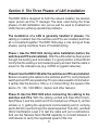
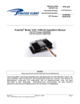
REAL WORLD CERTIFIERTM
A whole new world of testing possibilities!
MODEL RWC1000
USER’S GUIDE
★ ★ TEST
D DISPLA
Y
AN
S
S
★★
CAT
3,5,5E,6
CA
B
CABLE CATEGORY
*DIGITAL TEST
3*
5*
EXIT
5E*
6*
REVIEW
Revision 4
CATEGORY
LE
Limited Warranty
The manufacturer warrants to the original consumer that this product
is in good working order for a period of one year from the date of
manufacture or date of purchase. During this period the product will
be repaired or replaced without charge for either parts or labor. The
warranty does not cover damage caused by improper use or abuse
including connecting to high voltage. Repair or replacement as provided
under this warranty is the exclusive remedy of the purchaser.
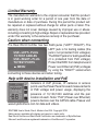
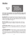
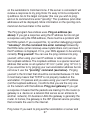
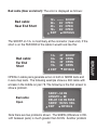
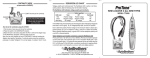
Caution when connecting
The Real World Certifier has two RJ45 jacks ("LEFT","RIGHT"). The
LEFT jack is for testing cables (the
jack is not protected from voltages).
USE <LEFT> PLUG
The RIGHT jack is for testing switches
TO TEST CABLES
(it is protected from PoE voltage).
USE <RIGHT> PLUG
Protect the RWC from telephone and
TO TEST PORTS
Power over Ethernet (PoE) voltages
MENU
by using the "RIGHT" socket when
connecting to these devices and when toning.
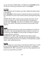
Help with device installation and PoE
Installers of VoIP phones, IP cameras or access
points use the Power Panel for exact measurements
of PoE voltage and power usage, displaying the
presence of 10,100,1000 switches and the pair
location of each. Note: "PoE" (Power over Ethernet)
powers devices over the CAT5/6 cable. Please visit
www.bytebrothers.com for data and videos.
RWC1000 User's Guide, Rev 4. Made in the USA. Copyright 2010.
Metric version available with display and reports in metric units.
Real World Certifier and Real World Certification are trademarks of Byte Brothers.
Microsoft and Excel are registered trademarks of the Microsoft Corporation.
Table of Contents
Section I. Introduction........................................................
2
Real World Certifier list of functions........................ 4
Section II. The Three phases of LAN installation.............
5
6
Section III. Faceplate description......................................
Section IV. Documenting testing results.........................
8
Section V. Operation...........................................................
9
Powering up and backlighting.................................
9
Navigation button.................................................... 10
RWC1000 Main Menu................................................... 11
Cable Testing................................................................ 12
Cat 5/6 UTP Cable Testing................................ 12
Cat 5/6 UTP RWC Level 1................................ 13
Cat 5/6 UTP RWC Level 2................................ 18
Reviewing Cat 5/6 UTP Test Results................ 21
Cat 5/6 UTP Basic Test.................................... 30
Coax Testing...................................................... 33
Naming / Saving Test Results.....................................
Reviewing/Erasing Printer Memory ...........................
Printing from a PC........................................................
35
39
41
Network Testing............................................................ 46
Scan one port................................................... 47
Monitor INLINE................................................. 50
Send Beacon.................................................... 53
Appendix A. Straight thru cable coupler.............................
Appendix B. Ping and TCP/IP debugging tools..................
Appendix C. Examples of UTP cable faults........................
Appendix D. Making a correct UTP cable.........................,,
54
55
60
63
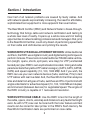
Section I. Introduction
Over half of all network problems are caused by faulty cables. And
with network speeds exponentially increasing, the need for affordable,
sophisticated test equipment is more apparent than ever before.
The Real World Certifier (RWC) and Network Tester is break-throughtechnology that brings cable and network certification and testing to
a whole new level of reality. It opens up a whole new world of testing
opportunities to network cabling professionals and managers that, prior
to the Real World Certifier, could only dream of performing speed tests
on their cable and LAN devices and printing the results.
WORKS WITH UTP AND ALL ETHERNET DEVICES: Unlike traditional
certifiers, the RWC uses digital circuitry and digital testing techniques to
perform its tasks. These tests include traditional TIA568 cable verification (length, opens, shorts, split pairs, wire map) for UTP (unshielded
twisted pair) plus RWC's own sophisticated crosstalk, timing and cable
parameter tests that yield a UTP cable's category (CAT3, CAT5, CAT5E,
CAT6) and speed capability (10, 100, 1000 MB)! And if you wish, the
RWC can use your own network devices (hubs, switches, PCs) to test
UTP cables with real live data! And, the Real World Certifier analyzes
links and data from all types of hubs, switches and PCs. It performs both
single sided tests for advertised speed (10, 100, 1000 MB and duplex)
and inline tests (between devices) for negotiated speed. The engine of
the RWC circuitry is capable of 1 nanosecond resolution.
WORKS WITH COAX CABLE: Use the RWC to test for the length of
the cable, opens, shorts, wiremap and distance to any faults that might
exist. As with UTP, coax can be toned with the toner feature and test
results can be stored for later printer in the RWC's flash memory. No
Real World Certification tests are performed on coax cable.
2
What is Real World Certification?
Real World Certification means that a UTP cable passed a prescribed
battery of tests and is therefore not likely to cause problems later. The
Real World Certifier has two levels of verification/certification:
RWC Level 1: Performed with the Main Unit and the Remote
Probe, Level 1 tests the cable for length; opens, shorts, split pairs
and distance to the fault; wire map (displays cable wiring); NEXT
and FEXT (crosstalk tests); propagation delay (time to transit
cable); skew (time delay between pairs); cable category (CAT3, 5,
5E, 6); and speed projection (10, 100, 1000 MB).
RWC Level 2: Includes all Level 1 tests plus takes advantage of a
real live data source (hub, switch or PC) to test for attenuation and
device type. The result is RWC Level 2 speed certification of the
cable and the LAN device.
Networks are installed in steps. First, cables are installed. Then hubs,
switches and PCs follow. Cables and network interfaces are known as
the physical layer. The higher software layers provide addressing, file
transfers. etc. If the physical layer does not work, the communications
layers (software) will not work. Debugging cables, ports and network
software together is time consuming, frustrating and ultimately very
expensive.There are too many unknowns. Real World Certifying cables
eliminates unknowns, making it easier to get a network up and running.
And, once the hardware is operational you can run software layer tests
(ping, etc. ) from any workstation (see Appendix B).
What is the best time to Real World Certify a cable?
The best time to certify a cable is when the installer is still readily
available to repair any faults that are found. Installers should certify
before they leave, so that they will not lose money by having to
return to a job site to do in warranty repairs. Network professionals
should certify before the warranty period expires.
3
The RWC1000 List of Functions
UTP CABLES. Real World Certification Level 1 tests:
✔ Length measurement of each cable pair.
✔ Locates opens, shorts and distance to the fault.
✔ Locates split pairs and the distance to the split.
✔ Wire map. Graphs cables internal pairing.
✔ NEXT (near end) and FEXT (a far distance) crosstalk.
✔ Propagation delay (time for data to travel the length of the cable).
✔ Skew (time delay between pairs).
✔ Cable typing. CAT 3, 5, 5E, 6.
✔ Speed Projection: Displays test results as a graph
projecting the cable’s speed capability (up to 1 GIGABIT).
UTP CABLES. Real World Certification Level 2 tests. Adds:
✔ Attenuation. Graphs level of real live data from PC, hub or switch.
✔ Speed Certification (Level 2). Enhanced speed display samples
real live data on active pairs to the limit of the device (1 Gig).
Note: Level 2 tests use real data from your hub, switch or PC.
COAX CABLES:
✔ Length, open, shorts, distance to fault, tone and wire map.
NETWORK DEVICE TESTING:
✔ Single Sided and INLINE port tests check the ability of the hub,
switch or PC to communicate by displaying their advertised and
negotiated capabilities.
✔ Data signal strength. Single sided test exercises the suspect hub,
switch or PC and displays the data signal strength of active pairs.
NAMING TEST RESULTS, PRINTER AND TONER PROBE:
✔ Naming tests. Test names can be up to 16 characters each.
✔ Toner/probe. Includes a full featured toner/probe. Tones coax and
all 4 UTP pairs to locate wires in crowded wiring closets.
✔ Printer memory. Stores test results for up to 250 UTP and coax
tests for later printing (requires a PC with Excel®). USB data
transfer cable and software included.
4
Section II. The Three Phases of LAN Installation
The RWC1000 is designed for both the network installer, the network
repair person and the IT manager. The tests used during the three
phases of LAN installation can just as well be used to troubleshoot
LANs that are suffering operational problems.
The installation of a LAN is generally handled in phases. The
cabling is installed; then the switches and PCs are installed; and then
all is connected together. The RWC1000 plays a role during all three
phases, saving countless hours of troubleshooting.
Phase I. Use the RWC1000 during cable installation (before the
switches and PCs are installed). After the LAN cable has been pulled
through the building and terminated, it is good practice to Real World
Certify that the cabling is terminated properly and test that the cable is
proper for the intended use (e.g. CAT5E for gigabit networks).
Phase II. Use the RWC1000 after the switches and PCs are installed.
Before connecting the cables to the switches and PCs, verify that each
switch port and PC are operational.This provides a wealth of information:
It verifies that the device is ON (i.e. it is transmitting); the speed of the
device (10, 100, 1000 MB/s) ; duplex; and other features.
Phase III. Use the RWC1000 when connecting the cabling to the
switches and PCs. With the cabling verified and Real World Certified (Phase I) and the switch and PCs checked out (Phase II), all that
remains is 1) getting the equipment communicating and 2) verifying
each LAN link is performing at the speed expected. To do this, use Real
World Certification Level 2 to test the cable and port combinations.
And use the Network Tests INLINE capability to connect between 2
LAN devices to verify the negotiated speed of the link.
5
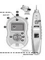
Section III. RWC1000 Faceplate Descriptions.
RWC1000 MAIN UNIT
The MAIN UNIT connects to any Cat 5/6, coax cable or 10,
100, or 1000 Base-T device and performs a host of tests
needed for their installation and repair. For certain tests, it
can be inserted inline between two LAN devices.
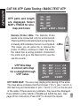
Main Unit Jacks
LEFT, COAX and RIGHT: Use the LEFT jack for UTP
TESTING. Use RIGHT jack for NETWORK TESTING.
➊
➋
"Printer" port
Use to transfer stored testing data (up to 250 tests) to a PC.
Requires Excel®. USB data transfer cable included.
➌
Power and LCD backlighting
Press the recessed power button. To backlight the display,
press the SEL button during the opening screen. The
RWC1000 powers OFF if there is no activity for 10 minutes.
➍
Cursor and SELECT buttons
Use the cursor buttons to select the function to be performed. Press the SEL button to select the functions.
➎
RWC1000 REMOTE PROBE
The Remote Probe performs 2 functions:
Tracing cables: Use it as an inductive probe to trace
cables with the tone generated by the Main Unit.
Far end cable termination: The Remote Probe's
jack is used to terminate the far end of the cable
when the wire map test is conducted.
6
➏
➐
➋
RJ45/COAX
ADAPTER
FOR PROBE
MAIN UNIT
➋
➋
➊
➌
➏
➍
➍
➎
➎
➎
9V BATTERY
COMPARTMENTS
REMOTE PROBE
7
➐
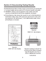
Section IV. Documenting Testing Results
The Real World Certifier includes 3 ways to document your test results.
1) A custom tablet can be used to fill in the test results (included).
2) "PASSED" stickers can be applied to wall outlets and LAN
devices to Real World Certify their capability (included).
3) Printer Memory that stores test results for up to 250 Real World
Certification tests, basic UTP tests and coax tests for later printing (requires a PC with Excel®). A 6' USB transfer cable, driver
and software is included.
Reorder:
RWC1011 (96 stickers)
Reorder:
RWC1007 (50 sheets)
Transfer readings to Excel® for
printing (serial cable included).
See the Readme.doc file on
CD for USB/serial converter
instructions.
8
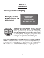
Section V
OPERATION
Powering up and backlighting
REAL WORLD
CERTIFIER
REVISION 800K1
SEL BACK LITE ON
Backlight selection
screen (lighting the
LCD display)
TURNING ON: Press the power button (PWR) and
release to turn ON the tester. The "backlighting"
screen appears (above). Pressing the select (SEL)
button while this screen is present turns on LCD lighting ("backlighting"). Backlighting is important when
working in dim light but shortens battery life.
Note: Once enabled, the LCD will remain backlit until the tester is powered
OFF.The backlight selection screen (above) is always lighted during the
3 second period that it is displayed. This allows you to turn the tester
ON in a dark area and SELECT backlighting during the process.
9
The Main unit's navigation button
How to navigate through the Real World Certifier screen:
PWR. Power ON/OFF (see prior page for backlighting).
SEL (SELECT). Press to perform task. Appears as on LCD.
The UP arrow. Appears as on LCD.
The DOWN arrow. Appears as on LCD.
The SELECT button's function always selects the task. But the function
of the UP and DOWN arrow buttons may change with each screen. For
example, the Main Menu (above) uses the UP arrow button to return
the tester to the MAIN MENU and uses the DOWN arrow button to
scroll the cursor.
10
Main Menu
RWC1000
Menu
CAT 5/6 UTP
COAX CABLE
NETWORK PORTS
PRINTER MEMORY
EXIT SCROLL SEL
This menu is the gateway to all of the RWC1000's tests. Scroll
the cursor with the down arrow button and press SELECT to
perform the task.
CAT5/6 UTP: Test and Real World Certify UTP cables with or without
LAN devices (hubs, switches, PCs) connected. Perform basic cable
tests on UTP cables. Tone UTP cables. Move the cursor to CAT 5/6
UTP and press SELECT. Page 12.
COAX CABLE: Test coax cables for length, opens, shorts, distance to fault and wiremap. 2 adapters included. Tone coax cables.
Page 33.
NETWORK PORTS: Perform tests on LAN (hubs, switches, PCs)
devices. Move the cursor to NETWORK PORTS and press SELECT.
Page 46.
PRINTER MEMORY: Printer memory is used to store the results
of up to 250 RWC Level 1, Level 2, basic tests and coax tests for later
printing. Move the cursor to PRINTER MEMORY and press SELECT
if you want to Review the tests stored in memory or Erase memory.
Page 40.
11
CAT 5/6 UTP
CAT 5/6 UTP Cable Testing Main Menu
UTP Cable Testing
Main Menu
SELECT TEST:
RW CERTIFY UTP
BASIC TEST UTP
TRACER TONES ON
EXIT SCROLL SEL
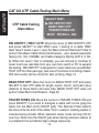
RW CERTIFY ("RWC") UTP: Move the cursor to RW CERTIFY UTP
and press SELECT to start RWC Level 1 testing of a cable. RWC
tests have 2 levels: Level 1 uses the Main Unit and Remote Probe to
perform the Basic Cable Tests (listed below)... plus Speed parameter
testing (10, 100, 1000MB) and Cable Category Testing (CAT 3, 5, 5E,
6). When the Level 1 test is complete, you can choose to continue to
Level 2 and use real data from your own hub, switch or PC to expand
the testing. RW CERTIFY is designed for 4 pair cable only (use BASIC
TEST UTP for other pairings). See List of Functions for a listing of tests.
250 test results can be stored for later printing. Page 13.
BASIC TEST UTP: Move the cursor to BASIC TEST UTP and press
SELECT to test UTP cable for length, opens, shorts, split pairs (plus
distance to these faults) and wire map. BASIC TEST UTP does not
perform Real World Certification. Page 30.
TRACER TONES ON: Move the cursor to TRACER TONES ON and
press SELECT if you wish to energize a cable with a tone (plug the
cable into the Main Unit's RIGHT jack). The Remote Probe detects
the tone at the far end of the cable. This is useful in locating cables in
crowded wiring closets. When selected, tracer tones will stay ON for
one hour. Note: Use the RIGHT jack when tracing unknown cables (it
is protected from accidental high voltage exposure).
12
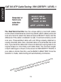
RW CERTIFY UTP
Perform Real World
Certification Level 1 (UTP
cables) and Level 2 (UTP
cables and LAN devices)
UN-COIL CABLE
PLUG OPEN CABLE
INTO LEFT PLUG
DO NOT USE PROBE
EXIT
TEST
Press down arrow
button after cable
is connected
Follow the instructions. Only an uncoiled cable will give you accurate
test results. At this point in the testing, the far end of the cable should
not be connected to any device. Note: If the cable is connected to a
device you will be alerted to check the far end of the cable. When ready
to proceed, press the down arrow ( TEST).
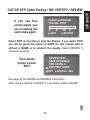
Error Messages: If there is a problem that stops the test from proceeding, one of the following error messages will be displayed:
CABLE IS ACTIVE: There is an active network port on the far end
of the cable. You will need to unplug it to proceed.
CHECK CABLE END: A voltage is present on one or more of the
cable pairs or the REMOTE PROBE is connected to the cable end
when it is not needed. You will need to unplug it to proceed.
NO CABLE: There is no cable connected or an inactive port is
plugged into the far end of the cable.
Note: If errors persist from test to test, please contact the factory.
13
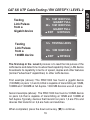
CAT 5/6 UTP
CAT 5/6 UTP Cable Testing / RW CERTIFY / LEVEL 1
CAT 5/6 UTP
CAT 5/6 UTP Cable Testing / RW CERTIFY / LEVEL 1
SELECT CABLE
PATCH 20' MIN
SOLID 20' MIN
Stranded or
Solid wire
selection
screen
EXIT
SCROLL SEL
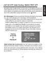
The Real World Certifier has the unique ability to test both cables
constructed of stranded wire (commonly called "patch" cables) and solid
core wire. Scroll to select the cable and press SELECT. How to tell the
difference: If the cable is installed in a wall, it is almost certainly a solid
core wire. Preassembled cable with end fittings already attached is
usually stranded cable. Also, stranded cable is more flexible than solid
wire. If you bend the cable and it does not attempt to spring back to its
original shape it is most likely solid cable. Note: The minimum length
of each cable type is shown on the screen for RW CERTIFY TESTS. If
your cable is shorter than this, use the BASIC CABLE TEST. Once the
selection is made, cable testing will automatically commence.
in
found
n be l.
a
c
s
reen e manua
ult sc
th
st res ection of
e
t
ll
a
s
f
o
W
tions Y/REVIE
scrip
F
E: De CERTI
T
O
N
W
the R
14
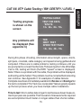
Testing progress
is shown on the
screen
Any problems will
be displayed (See
appendix C)
TESTING CABLE
TEST FOR DATA
*SPLITS
12> 36> 45> 78>
TDR
NEXT FEXT
SPEED TEST PAIRS
12> 36> 45> 78>
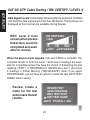
During this phase of testing, information about length, opens, shorts,
split pairs, crosstalk, cable category and speed is being gathered and
computed. If there are no cable problems, testing continues until you
are prompted to connect the Remote Probe and perform the Wire Map.
If all is OK, testing will finish (the RWC "speed" screen is displayed).
Note: If there is a problem with the cable, the problem will be displayed,
and testing will be halted. The problem must be corrected before testing
can continue. See Appendix C for examples of cables failures.
Complete results are immediately available for Review and Saving after
the test is completed.This "test now, review later" feature greatly speeds
up the test process when you have multiple cable installations.
Time to test: Short-cables take longer to test because fewer measurements per pass are possible. The thousand of measurements required
are accomplished much faster on longer cables than shorter cables.
15
CAT 5/6 UTP
CAT 5/6 UTP Cable Testing / RW CERTIFY / LEVEL 1
CAT 5/6 UTP
CAT 5/6 UTP Cable Testing / RW CERTIFY / LEVEL 1
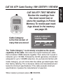
Testing is halted
until the Remote
Probe is connected.
PLUG IN PROBE AT
FAR END OF CABLE
<RED LED = DONE>
TRACE TONES ON
EXIT
The REMOTE PROBE is required for the WIRE MAP to be constructed. Plug the Remote Probe into the far end of the cable. Tracer
tones have been turned ON to help locate cables in crowded areas
(press the TRACE button on the Remote Probe and hold it close to
the cable to follow the tone). The Main Unit's wire map test is triggered
when the Remote Probe is connected to the far end of the cable
(there are no buttons to push). The wire map tests for correct cable
pairing. Note: The wire map is displayed during the Review process.
Not during the test.
Remote Probe LEDs. The Remote Probe
needs to be connected only for a brief period.
Flashing LED(s) indicate the test is progressing.
A steady LED indicates the test is completed.
This saves you an extra trip to retrieve the
LEDs
probe. If LED(s) continue to flash the cable,
the cable has a wiring problem. Disconnect
the probe and go to the Main Unit to see
the see the results. Note: If you plan to test
to Real World Certification Level 2, now is a
good time to plug in the hub, switch or PC (it
will save you a trip).
16
RWC Level 1 final
screen (when you see
this, Level 1 is completed and available
for review)
<<< PASSED >>>
*DIGITAL TEST
3*
5* 5E* 6*
EXIT REVIEW/SAVE
When the above screen appears, the Level 1 RWC is complete. If
you select REVIEW/SAVE, you will enter the Test Results Option
Screen. To discard the test results immediately, select EXIT.
Test results
option screen
REVIEW TEST
SAVE READINGS
RWC TEST PORT
EDIT TEST NAME
EXIT SCROLL SEL
REVIEW TEST: View results from the Level 1 test. After the review, you
may return to this screen to NAME/SAVE the results. See page 21.
SAVE READINGS: Store the test results in PRINTER MEMORY for
later printing and do not continue to Level 2 testing. The next sequential
Reading Number (1-250) will be assigned along with any name that
has been created (see EDIT TEST NAME below).
RWC TEST PORT: Continue to Level 2 certification. Requires a PC,
hub or switch to drive the cable. See page 18.
EDIT TEST NAME: Create a name (not required) that is stored with
the sequential reading number. If you continue to Level 2 you will have
another chance to create a name. See page 35.
EXIT: Discards the test results and returns to the Main Menu.
17
CAT 5/6 UTP
CAT 5/6 UTP Cable Testing / RW CERTIFY / LEVEL 1
CAT 5/6 UTP
CAT 5/6 UTP Cable Testing / RW CERTIFY / LEVEL 2
RW CERTIFY UTP
LEVEL 2
Perform Real World
Certification Level 2 (UTP
cables and LAN devices)
If you have selected
to continue with Real
World Certification
Level 2, this screen
appears.
PLUG IN PORT
GIG PORT MAY
RW CERTIFY TO
10M 100M 1 GIG
EXIT
CERT 2
Real World Certification Level 2 adds to the battery of tests conducted
in Level 1 by testing the cable with real live data. The source of this data
can be any hub, switch or PC. Note: The screen (above) reminds you
that the best source of data is a gigabit device. A gigabit device drives
the cable with data up to a gigabit (1000 MB) on all 4 pairs.
Connect the port to the cable and press
to continue with Level 2.
FAQ: What is the difference between Level 1 and Level 2 and when do
I use it? Level 1 certification tests for length, opens, shorts, split pairs
(including distance to the fault) along with propagation delay, skew,
NEXT, FEXT, and Cable Category measurements. Level 1 testing uses
simulated digital signals to test the cable. Level 2 adds to the testing
with the use of real live data from a NIC, hub, or switch. Use Level 1
for new cable installations or anytime a LAN device (hub, switch, PC)
is not available.
18
Testing
Link Pulses
from a
Gigabit device
12> 10M 100M FULL
GIGABIT FULL
36> 10M 100M FULL
GIGABIT FULL
EXIT
DETAILS
Testing
Link Pulses
from a
100MB device
12> TESTING LINKS
36> 10M 100M HALF
EXIT
DETAILS
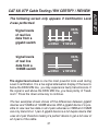
The first step in the Level 2 process is to read the link pulses of the
LAN device and determine its advertised capability. Every LAN device
broadcasts its capability in terms of speed, duplex and other features
(termed "advertised" capabilities) to other LAN devices.
First example (above): The RWC1000 has found a gigabit device
(1000MB) on pairs 1,2 and 3,6 that is capable of transmitting at 10MB,
100MB and 1000MB at full duplex. 1000 MB devices use all 4 pairs.
Second example (above): The RWC1000 has found a 100MB device
on pairs 3,6 that is capable of transmitting at 10MB and 100MB at
half duplex. Typically, devices that transmit on pairs 1,2 are PCs and
devices that transmit on 3,6 are hubs and switches.
When completed, press the down arrow key ( ) to continue.
19
CAT 5/6 UTP
CAT 5/6 UTP Cable Testing / RW CERTIFY / LEVEL 2
CAT 5/6 UTP
CAT 5/6 UTP Cable Testing / RW CERTIFY / LEVEL 2
Data Signal Levels: Immediately following the link pulse test, the Main
Unit tests the data signal levels from the LAN device. The levels are not
displayed at this time but are available during Review.
RWC Level 2 final
screen (when you see
this screen, Level 2 is
completed and available for review).
RW CERTIFIED
1 GIG
10
100
1000
EXIT
REVUE/SAVE
When the above screen appears, the Level 2 RWC is complete. The
complete results of both the Level 1 and Level 2 readings are available for immediate review. You have the choice of discarding the test
readings ("EXIT") or REVIEWING or SAVING the Level 1 and Level
2 readings in Printer Memory ("REVUE/SAVE"). Note: If you select
REVIEW/SAVE, you will have an option to name the test (EDIT TEST
NAME) before saving.
Review, create a
name for the test
and/or save the test
results.
REVIEW TEST
SAVE READINGS
RWC TEST PORT
EDIT TEST NAME
EXIT SCROLL SEL
20
CAT 5/6 UTP TEST REVIEW
Review the readings from
the most recent test or
store the readings in Printer
Memory. To review past readings stored in the memory
see page 39.
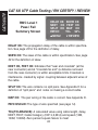
CABLE CATEGORY
*DIGITAL TEST
Cable Category
is the first screen of
many that are stored
3*
5*
EXIT
5E* 6*
REVIEW
The "Cable Category" is universally accepted as the speed
capability of the cable. Cat 3 was the original twisted pair cable
that connected 10MB networks together. Then came Cat 5 (used in
networks up to 100 MB). Followed by Cat 5E (generally considered
adequate for up to 1000MB networks). As you become familiar with
Cable Category, you will notice that few cables get rated higher than
their factory labeling. This is because cables are manufactured and
tested to minimum specifications. If the cable exceeds minimum
specifications it passes the manufacturer's inspection.
When ready to proceed, press ( ) REVIEW.
21
CAT 5/6 UTP
CAT 5/6 UTP Cable Testing / RW CERTIFY / REVIEW
CAT 5/6 UTP
CAT 5/6 UTP Cable Testing / RW CERTIFY / REVIEW
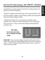
RW Certification
Level 1 Speed
Projection
REAL WORLD
CERTIFIED TO 100M
10
100
1000
MENU
REVIEW
Real World Certification Level 1 displays the projected speed capability
of the cable. The graph is a result of thousands of measurements used
to project the speed of the cable. This is one of the most useful and
money-saving displays. For instance, it is possible that some shorter,
installed CAT5 cable (rated for 100MB) are capable of communicating
at a 1000MB. This graph will indicate such. Many users conclude their
cable testing with Level 1 and skip the Level 2.
22
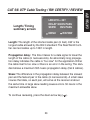
LENGTH = 201'
DELAY 304NS PASS
SKEW 3NS PASS
Length / Timing
summary screen
MENU
REVIEW
Length: The length of the shortest cable pair (in feet). 330' is the
longest cable allowed by the 802.3 standard. The Real World Certifier can test cables up to 1250' in length.
Propagation delay: The time it takes for a data signal to travel the
length of the cable (in nanoseconds). An abnormally long propagation delay indicates the cable is "too slow" for the application. Either
the cable itself is too slow or there is an error in the wiring. The standard allows a maximum 555 nsecs propagation delay (Cat 6 cables).
Skew: The difference in the propagation delay between the slowest
pair and the fastest pair in the cable (in nanoseconds). A small skew
insures that data, on each pair, will arrive at the receiver at about
the same time. A large skew reading causes errors. 50 nsecs is the
maximum allowable skew.
To continue reviewing, press the down arrow key ( ).
23
CAT 5/6 UTP
CAT 5/6 UTP Cable Testing / RW CERTIFY / REVIEW
CAT 5/6 UTP
CAT 5/6 UTP Cable Testing / RW CERTIFY / REVIEW
RWC Level 1
Pass / Fail
Summary Screen
DELAY OK
NEXT OK
SPLIT OK
PATCH
MENU
SKEW OK
FEXT OK
MAP OK
TOL 94%
REVIEW
DELAY OK: The propagation delay of the cable is within specification. See page 23 for the definition of delay.
SKEW OK: The skew of the cable is within specification. See page
23 for the definition of skew.
NEXT OK, FEXT OK: Indicates that "near end crosstalk" (at the
near connector) and at "crosstalk far end" (a distance removed
from the near connector) is within acceptable limits. Crosstalk is
interference created by signal coupling between adjacent wires of
the cable.
SPLIT OK: The wire contains no split pairs. See Appendix D for a
definition of "split pairs" and notes on making a correct cable.
MAP OK: The pair wiring of the cable is correct. See Appendix D.
PATCH/SOLID: The type of wire specified (see page 14).
TOL(TOLERANCE): A calculated value using cable length, delay,
NEXT, FEXT, Cable Category (CAT 3,5,5E,6) and speed (10M,
100M, 1000M). Zero percent equals failure to meet
24
specifications at a given speed. One percent is barely passing. 100
percent is maximum tolerance.
Tolerance is largely cable length driven. The longer the cable is, the
less the tolerance. However, lower Category cables eat up tolerance
faster than higher Category cables.
If Tolerance is below 15%, you may wish to consider using a
repeater, hub or switch to shorten the cable run. This is especially
true if you are in a "noisy" environment (large electromechanical
machines, etc.).
12> 203'
36> 203'
45> 201'
78> 200'
MENU
Wire Map
A correct wire map
for a straight through
cable.
= = = <12
= = = <36
= = = <45
= = = <78
REVIEW
WIRE MAP: The wire map displays the pairing of the wires in the
cable. The example wire map indicates that the first pair (comprised
of pins 1 and 2) is 203 feet long and terminates in pins 1 and 2 on
the far end of the cable.
25
CAT 5/6 UTP
CAT 5/6 UTP Cable Testing / RW CERTIFY / REVIEW
CAT 5/6 UTP
CAT 5/6 UTP Cable Testing / RW CERTIFY / REVIEW
P ro p a g a t i o n
and skew (per
pair) screens
12> 309NS
36> 309NS
45> 305NS
78> 305NS
MENU
12> 4NS
36> 4NS
45> 0NS
78> 0NS
MNEU
DELAY
DELAY
DELAY
DELAY
REVIEW
SKEW
SKEW
SKEW
SKEW
REVIEW
Timing data per pair: The next two screens give you the timing of
the propagation delay and skew for each pair in the cable. Large
variations between pairs indicate trouble.
Note: A given pair's skew is the difference in propagation delay
between that pair and the slowest pair in the cable.
26
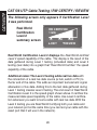
The following screen only appears if Certification Level
2 was performed.
Signal levels
of real live
data from a
gigabit switch
DATA
MIN
12 36 45 78
MENU
REVIEW
DATA
MIN
Signal levels
of real live
data from a
100MB switch
36
MENU
REVIEW
The signal level screen is one the most powerful tools used during
Level 2 certification. It is a live signal attenuation display. If the level is
below the DATA MIN line, you may experience faulty transmissions. If
the signal is well above the DATA MIN line, you have plenty of "headroom". Press the down arrow key to continue.
The two examples shown shows off the differences between gigabit
devices and 10MB and 100MB devices. With a gigabit device it is possible to view real live data on all 4 pairs whereas a 10MB and 100MB
can only transmit on 1 pair. A gigabit device is a full duplex device that
uses all 4 pair therefore making it a perfect device to get a full view of
all 4 pairs of the cable.
27
CAT 5/6 UTP
CAT 5/6 UTP Cable Testing / RW CERTIFY / REVIEW
CAT 5/6 UTP
CAT 5/6 UTP Cable Testing / RW CERTIFY / REVIEW
The following screen only appears if Certification Level
2 was performed.
Real World
Certification
Level 2
summary screen
RW CERTIFIED
1 GIG
10
100
1000
EXIT
REVIEW
Real World Certification Level 2 displays the Real World certified
Level 2 speed capability of the cable. The display is the result of the
data gathered during Level 1 testing (simulated data) and Level 2
testing (real data) into a graph that "Real World Certifies" the speed
capability of the cable.
Additional notes: The Level 2 testing adds real live data with
the connection of a real live data source (a hub, switch or PC) to
the far end of the cable. This adds an important test element: signal
attenuation of live data. Adding this to the test data gathered during
Level 1 testing creates Level 2 testing. The end result of Real World
Certification Level 2 is the speed graph shown above. It certifies the
measured data speed capability of the cable. Use Level 2 certification whenever you want to test a cable with real live data. With the
Level 2 testing you are Real World Certifying both your cable and
your network port at the same time (you can test your cable with the
exact port that it will use in the network).
28
CABLE CATEGORY
*DIGITAL TEST
If you see this
screen again, you
are reviewing the
same data again
3*
5*
EXIT
5E* 6*
REVIEW
Select EXIT at any time to stop the Review. If you select EXIT,
you will be given the option to SAVE the test results with or
without a NAME or to discard the results. Select REVIEW to
continue reviewing.
REVIEW TEST
SAVE READINGS
RWC LEVEL 2
EDIT TEST NAME
EXIT SCROLL SEL
Test results
option screen
"EXIT"
See page 35 for SAVING and NAMING instructions.
Note: Once a reading is SAVED, it is too late to create a NAME.
29
CAT 5/6 UTP
CAT 5/6 UTP Cable Testing / RW CERTIFY / REVIEW
CAT 5/6 UTP
CAT 5/6 UTP Cable Testing / BASIC TEST UTP
BASIC TESTING OF UTP
Test UTP for opens, short,
split pairs, length and
distance to fault.
UTP Cable Test
Main Menu
RW CERTIFY UTP
BASIC TEST UTP
TRACE TONES ON
EXIT
SCROLL SEL
BASIC TEST UTP: Move the cursor to BASIC TEST and press SELECT
to test a UTP cable for length, opens, shorts, split pairs (plus distance to
these faults) and wire map. BASIC TEST UTP is a quick test and does
not perform Real World Certification. Basic test results can be stored
in Printer Memory. Note: BASIC TEST UTP is often used when a cable
fails to pass the RWC test. Or it is used to test 2 pair UTP wiring (RWC
can only be performed on 4 pair wire).
Press down arrow
button after the
UTP cable is
connected
UN-COIL CABLE
PLUG OPEN CABLE
INTO LEFT PLUG
DO NOT USE PROBE
EXIT
TEST
Follow the instructions on the screen (plug the cable you wish to test
into the LEFT jack). Only an uncoiled cable will give you the most
30
accurate length measurement. At this point in the testing, the far end
of the cable should not be connected to any device. Note: If the far end
of the cable is connected to any device it will notify you to check the far
end of the cable.When ready to proceed, press ( TEST).
Error Messages: If there is a problem that stops the test from proceeding, one of the following error messages will be displayed:
CABLE IS ACTIVE: There is an active network port on the far end
of the cable. You will need to unplug it to proceed.
CHECK CABLE END: A voltage is present on one or more of the
cable pairs or the REMOTE PROBE is connected to the cable
end when it is not needed. You will need to unplug it to proceed.
NO CABLE: There is no cable connected or an inactive port is
plugged into the far end of the cable. Plug in the cable or disconnect the inactive port.
TESTING CABLE
TEST FOR DATA
*SPLITS
12> 36> 45> 78>
TDR
Testing
progress
is
displayed
Cable testing has commenced. You can follow its progress on the
display. During this phase of testing, information about length, opens,
shorts and split pairs is being gathered and computed. If any cabling
errors are encountered you will be alerted including the distance to
any problems..
31
CAT 5/6 UTP
CAT 5/6 UTP Cable Testing / BASIC TEST UTP
CAT 5/6 UTP
CAT 5/6 UTP Cable Testing / BASIC TEST UTP
UTP pairs and length
are displayed. Select
MAP + TRACE for wiremap and tones
12> 203'
36> 203'
45> 201'
78> 200'
EXIT MAP + TRACE
Remote Probe LEDs. The Remote Probe
needs to be connected only for a brief period.
Flashing LED(s) indicate the test is progressing.
A steady LED indicates the test is completed. LEDs
This saves you an extra trip to retrieve the
probe. If LED(s) continue to flash the cable,
the cable has a wiring problem. Disconnect
the probe and go to the Main Unit to see the
see the results.
UTP Wire Map
A correct wire map
for a straight through
UTP cable.
12> 203'
36> 203'
45> 201'
78> 200'
EXIT
= = = <12
= = = <36
= = = <45
= = = <78
SAVE
UTP WIRE MAP: The wire map displays the pairing of the wires.
The map above indicates that the first pair ("12>"), pins 1 and 2, is
203 feet long and terminates in pins 1 and 2 ("<12") on the far end
of the cable. If there were any problems, they would be displayed.
Press SAVE to either SAVE or NAME and SAVE the test. See
page 35 for instructions. Press EXIT to discard the results.
32
COAX CABLE TESTING
Test coax cable for opens,
short, length and distance
to fault.
CAT 5/6 UTP
COAX CABLE
NETWORK PORTS
PRINTER MEMORY
EXIT SCROLL SEL
Select COAX
CABLE from
Main Menu
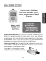
COAX CABLE TESTING: Move the cursor to COAX CABLE and press
SELECT to test a coax cable for length, opens, shorts (plus distance
to these faults). Wire map and toning is also available from this menu.
COAX CABLE test is a quick test and does not perform Real World
Certification. Test results can be stored in Printer Memory.
RJ45/COAX ADAPTER: The Main Unit has a permanent COAX connector labeled "COAX". The RJ45/COAX adapter is used to connect
the coax cable to the Remote Probe.
Pins 1 and 2 of the Remote Probe's
socket are used to test the coax cable.
33
COAX CABLES
COAX CABLE TESTING
COAX CABLES
COAX CABLE TESTING
Connect the coax
cable to the F
connector on the
Main Unit and select coax. The test
begins.
12> 105'
COAX
EXIT
MAP + TRACE
At the beginning of the test, the far end of the cable should
not be connected to anything.
The coax pair (pins 1
and 2) and length are
displayed. Select MAP
+ TRACE for wiremap
and tones
Coax Wire Map
A correct wire map
for a coax cable.
12> 105'
COAX
EXIT
MAP + TRACE
12> 105' = = = <12
EXIT
SAVE
Is the cable OK? If the COAX CABLE TEST concludes with a wire
map display and no reported errors, the cable is error free.
Press SAVE to either SAVE or NAME and SAVE the test. See
the next page for instructions. Press EXIT to discard the results.
34
NAMING / SAVING TEST RESULTS
Naming and Saving
test results start at
this screen
REVIEW TEST
SAVE READING
RWC TEST PORT
EDIT TEST NAME
EXIT SCROLL SEL
REVIEW TEST: Review test results before they are SAVED. After
reviewing the test results you can return to this screen.
SAVE READINGS: Store the results from the latest test in PRINTER
MEMORY for later printing. The next sequential Reading Number
(1-250) is automatically assigned along with any NAME that you
created (see EDIT TEST NAME below). Creating a name is not
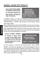
required. Note: The test results of all RWC1000 cable tests can
be NAMED and STORED with the exception of RWC tests that
did not "PASS".
RWC TEST PORT: For RWC UTP tests only. See page 18.
EDIT TEST NAME: Create a name (not required) that is stored
with the sequential reading number. If you are going to create a
name, it must be created before the test is SAVED. See the following page for instructions on creating a NAME.
EXIT: Discards the test results and returns to the Main Menu.
35
EDIT NAME
All RWC1000 tests, whether RWC UTP, Basic UTP or coax, eventually
arrive at this screen. It is here where you decide to SAVE the test in
PRINTER MEMORY (with or without a custom NAME).
NAMING / SAVING TEST RESULTS
EDIT NAME
Select EDITTEST NAME
to create a custom name
for the test results. Do
this before saving the
test in memory.
REVIEW TEST
SAVE READING
RWC TEST PORT
EDIT TEST NAME
EXIT SCROLL SEL
To NAME a reading, you must first complete any of the RWC1000's
cable tests. At the end of the test, press the DOWN arrow (labeled
"REVIEW/SAVE" or "SAVE") and the above screen appears. Select
EDIT TEST NAME.
Note: Creating a name (EDIT TEST NAME) for a test result is optional.
The RWC1000 automatically assigns a sequential number from 1 to 250
when SAVE READING is selected. If a name has been created using
EDIT TEST name, this name will also be stored with the sequential
number when SAVE READING is selected.
Select START FRESH
to create a name from
scratch. Select EDIT OLD
to create a new name by
modifying the prior name.
It saves time.
CREATE TEST NAME
START FRESH
EDIT OLD NAME
EXIT
SCROLL SEL
For the purposes of learning the naming routine, select START
FRESH and follow the exercises on the following page. Once you
become proficient with START FRESH, give the EDIT OLD routine a
try. It speeds creating names by allowing you to copy an "old" reading
name as the starting point for creating the next cable reading name.
See 2 pages ahead for more detail.
36
NAMING / SAVING TEST RESULTS
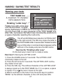
Naming your tests
TEST NAME line
A maximum 16 character
name appears here.
W
WXYZ
MENU #012
SELECT CHAR
The UP and DOWN arrows rotate the "LETTER LOOP"
to the right and left. The SEL key copies the letter to
the TEST NAME LINE. Create a label: Rotate the letter
loop until the letter or command desired appears at the
leftmost of the display and press the SEL button.
Exercise the "Rotating Letter Loop"
It's the best way to learn how to create a name.
Exercise #1. Moving the LETTER LOOP.
1) Press the DOWN arrow for 5 seconds: The LETTER LOOP
continually rotates to the left.
2) Press the UP arrow for 5 seconds: The LETTER LOOP continually rotates to the right.
3) Press the SEL key: The leftmost character of the LETTER LOOP
is always copied up to the TEST NAME line. If it is a space, a space
is copied. If it is a the cursor moves to the right.
4) Want to exit back to the menu? Use the arrow keys to position
"MENU" as the leftmost character on the LCD and press SEL.
37
EDIT NAME
Rotating "Letter loop"
LEFT RIGHT SEL
Rotate loop with arrow keys
until desired letter, number,
space, backspace or MENU command appears on the left edge
of LCD. Press SEL to copy character to the TEST NAME line.
After SEL is pressed, the letter loop conveniently positions to
a space character awaiting the next entry.
NAMING SAVING TEST RESULTS
EDIT NAME
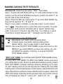
Exercise #2. Create the test name "TEST", then erase:
Step 1: Position the LETTER LOOP so "T" is the leftmost letter on the
screen (use the UP and DOWN arrow keys to position the letter "T" at
the left side of the LCD display).
Step 2. Press the SEL key, copying the "T" up to the TEST NAME line.
Now do the same for "E", "S" and "T".
Step 3. If you make a mistake, try the letter loop's "cursor characters" (
). They allow you to control the cursor's postion. To erase
a character, write over the character with a "space" (blank) character. There are 3 of these in the letter loop. For instance, a space
character is located between the "." character and the letter A.
Special characters in the LETTER LOOP
Backspace over letters without erasing them.
Forward space over letters without erasing them.
Space (blank). Use to erase letters or add spaces.
MENU Use to exit the EDIT TEST NAME routine and return to the
MENU. If you select MENU you have lost nothing. You can
still SAVE the reading in memory or re-enter the EDIT
TEST NAME routine.
"EDIT OLD" NAME Once familiar with the EDIT TEST NAME routine,
try using EDIT OLD NAME. The EDIT OLD NAME routine requires a
prior cable name to edit. Perform a cable test and when naming, select
EDIT OLD NAME. It speeds creating names by allowing you to copy
an "old" reading name as the starting point for creating the next cable
reading name. Use the backspace, forward space, space character and
other characters to modify the name. SAVE it when complete. Note:The
RWC1000 allows duplicate names but when they are printed in Excel
they will appear as "Jack A", "Jack A (2)", "Jack A (3)", etc.
38
REVIEWING PRINTER MEMORY
PRINTER MEMORY
Review or Erase stored
readings (memory stores
up to 250 readings).
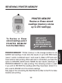
PRINTER MEMORY: "Printer memory" is the storage location for all
SAVED test readings. It can store the results of up to 250 RWC tests
(Level 1 and/or combined Level 1 and Level 2), Basic UTP tests and
coax tests for later printing. After each test is conducted, you have the
option to REVIEW, SAVE and/or NAME the test results (readings) in
PRINTER MEMORY for later printing. This following screen is used
if you wish to REVIEW the readings after they have been stored. It is
also used to ERASE all of the stored readings.
See page 41 for connecting the Real World Certifier to the PC for data
transfer and printing.
39
MEMORY
CAT 5/6 UTP
COAX CABLE
NETWORK PORTS
PRINTER MEMORY
EXIT SCROLL SEL
To Review or Erase
stored readings, select
PRINTER MEMORY
from the Main Menu
REVIEWING PRINTER MEMORY
Review or Erase
selection screen
REVIEW MEMORY
ERASE MEMORY
EXIT
MEMORY
REVIEW: Use the UP and DOWN
arrow to find the reading you wish
to review in Printer Memory. Press
SEL to review. "BLANK TEST
NAME" indicates a name has not
been created for the test.
ERASE: Selecting the ERASE
function erases all of Printer
Memory. There is no way to selectively erase readings. This screen
verifies that you wish to erase all
of Printer Memory.
SCROLL SEL
READING #
1
BLANK TEST NAME
UP
DOWN SEL
ERASE READINGS
ERASE ALL MEMORY
NO> NOT SURE
YES> VERY SURE
EXIT SCROLL SEL
FLASH MEMORY: The test readings are stored in nonvolatile (flash)
memory. The stored readings will remain until the "ERASE" function
is performed. Powering OFF the tester or unplugging its battery will
not affect the memory contents.
UNDERSTANDINGTHE READINGS: The display of the stored readings
follows the same sequence as if you reviewed the
test immediately after the test was conducted. See page 21.
40
PRINTING FROM A PC
Transfer the test readings from the Main Unit
to the PC using the supplied cable, driver and
software (requires Microsoft® Excel®)
USB micro B
plug
USB port
PC with Excel
and a USB port
RWC1000 with up to 250
stored readings
STEP 2: TRANSFERRING TEST READINGS (RWC TO PC):
1) Connect the RWC to a USB port on your PC and turn the RWC ON.
2) Run the "RWC1000.xls" spreadsheet (found on the RWC software
CD). RWC1000.xls is itself an Excel spreadsheet that uses Excel's
built-in macros to transfer the test results to your PC. Run RWC1000.xls
directly from the CD or copy it to your hard drive. Follow the directions
on the Excel screen to transfer the readings from the RWC's Printer
Memory. 3) If you wish, print some or all of the tests (each test prints
on a separate sheet). Or email the file to your customer as proof of
test. 4) Save the file using Excel's File>"Save as". See the Readme.
doc file on the RWC software CD for more details.
41
PRINTING
STEP 1: INSTALL THE RWC DRIVER ON PC: Run "install_driver.
exe" (found on the RWC software CD). This driver is needed for the
PC to talk to the RWC (ignore other drivers). The RWC does not
need to be connected to the PC for the driver to properly install.
PRINTING FROM A PC
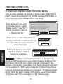
STEP-BY STEP INSTRUCTIONS FOR USING EXCEL:
After you have installed the driver and connected the RWC1000 to
the PC, launch Excel. Select FILE, OPEN and select RWC1000.xls
(either from your RWC software CD or hard drive).
Microsoft Excel
Excel asks you if you wish
to "Enable macros". Select
"Enable macros". Say "No" if
asked if you want to open as
a "Read Only" file.
The workbook you are opening contains macros.
Some macros may contain viruses taht could be harmful to your computer.
If you are sure this workbook is from a trusted source, click
"Enable Macros". If you are not sure and want to prevent
any macros from running click "Disable "Macros".
Excel alerts you that it has not found
the tester. Click OK to continue and use
the Import Report routine (below) to
locate the tester. .
PRINTING
Enable Macros
Disable Macros
The Import Report screen with
3 buttons appears. "Detect
Testers" is automatic.
Do Not Open
Microsoft Excel
No network testers found
OK
Import Report
Serial Port
Detect Testers
Com1
Import Readings Edit Report
Detect Testers The RWC spreadsheet's first step is to automatically
assign a COM (serial) port to your USB connection and detect the
RWC tester. The COM port number selected is displayed in the
window (1 through 9 is acceptable). The "Import Reading" button will
only be enabled if a RWC tester is detected. If Detect Testers does
not work, it will respond with the error message "No Network Testers
found." Verify the tester's power is ON and try again. If the problem
still persists, see "Error messages" on the following page.
42
PRINTING FROM A PC
Microsoft Excel
Press the Import Readings button
next. It downloads data from the serial port specified in the drop down box. Press OK.
Import Readings
Download from network
tester successful!
OK
Error messages: If Excel says "Please select a serial port with
a network tester connected" or "No network testers found", communication is not established with the RWC's USB port. First check
the connections; is the USB cable firmly connected; is Excel's macro
security set to low; and the RWC powered ON. For more help, see
README.DOC on the RWC software CD and the videos at www.
bytebros.com/bb_tester/tech_support/RWC1000_tech_support.htm. It
shows you the step-by-step installation procedure.
Edit Report
Readings
Select and change reading names below:
Rack 5 Jack 3
Rack 5 Jack 4
Rack 5 Jack 5
Room 18 Jack 1
Room 18 Jack 2
Room 18 Jack 2A
Room 18 Jack 2B
Reading #:
4
Reading Name:
Room 18 Jack 1
Back
Finish
The sequential number (1-250) automatically assigned by the
RWC1000 to each stored test will appear as "Reading: Cable#1,
Reading: Cable#2", etc. in the spreadsheet along with any custom
name that you created. The "Reading #" can only be modified in the
spreadsheet. Note: The RWC1000 allows duplicate custom names
but when they are printed in Excel they will appear as "Jack A",
"Jack A (2)", "Jack A (3)", etc. unless you change the name here.
43
PRINTING
Edit Report
After
the readings are
downloaded, press to
launch the spreadsheet.
If you wish to change
any NAMES that you
created, do it in this
opening screen. You can
wait until they are in the
spreadsheet but it is
quicker here.
PRINTING FROM A PC
PRINTING
When satisfied, press Finish. The spreadsheet named
"RWC1000.XLS" will appear. One cable test reading occupies one
worksheet. You can do anything with this spreadsheet as would with
any Excel spreadsheet (save it under a different name, change the
names in the cells, etc.). When you are ready to print, select FILE,
PRINT and in the PRINT WHAT dialog box select ALL. All of the
cable test readings will print (one per page).
C
A
D
E
B
1 Reading: Cable# 1
2 Length
Delay
Skew
Patch/Solid
3 25 ft.
38ns
2ns
Patch
4 CERT LEVEL 1: 1 GIG, 100% TOL
5 CERT LEVEL 2: 1 GIG, 100% TOL
6 NEXT PASSED (DIGITAL TEST)
7 FEXT PASSED (DIGITAL TEST)
8 SPLIT PAIRS PASSED
9
10
11 WIREMAP:
12> 25' === <12
12
36> 26' === <36
13
45> 26' === <45
14
78> 26' === <78
15
16 PROPAGATION
SKEW
12>
38ns DELAY
17 DELAY (PER PAIR)
36>
39ns DELAY
18
45>
39ns DELAY
19
78>
39ns DELAY
20
21
22
Cable# 4 Cable# 3 Cable# 2 Cable# 1
F
12>
36>
45>
78>
RWC1000.XLS spreadsheet
44
G
0ns SKEW
1ns SKEW
1ns SKEW
1ns SKEW
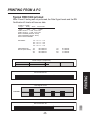
PRINTING FROM A PC
Typical RWC1000 printout
Note: If Level 2 testing was not performed, the Data Signal Levels and the RW
Certification #2 charts will have no data.
Reading: Cable# 1
Length
Delay Skew
Patch/Solid
25 ft.
38ns
2ns
Patch
CERT LEVEL 1: 1 GIG, 100% TOL
CERT LEVEL 2: 1 GIG, 100% TOL
NEXT PASSED (DIGITAL TEST)
FEXT PASSED (DIGITAL TEST)
SPLIT PAIRS PASSED
WIREMAP:
12>
36>
45>
78>
PROPAGATION
DELAY (PER PAIR)
12>
36>
45>
78>
25' ===
26' ===
26' ===
26' ===
<12
<36
<45
<78
12>
36>
45>
78>
38ns DELAY
39ns DELAY
39ns DELAY
39ns DELAY
0ns SKEW
1ns SKEW
1ns SKEW
1ns SKEW
Cable Category (Digital test)
CAT3
CAT5
CAT5E
CAT6
10MB/S
100MB/S
PRINTING
RW Certification #1
1000MB/S
Data Signal Levels
Data Min
PAIR 1,2
PAIR 3,6
PAIR 4,5
RW Certification #2
10MB/S
100MB/S
1000MB/S
45
PAIR 7,8
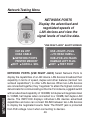
Network Testing Menu
NETWORK PORTS
Display the advertised and
negotiated speeds of
LAN devices and view the
signal levels of real live data.
"USE RIGHT JACK" ALERT SCREEN
NETWORKS
CAT 5/6 UTP
COAX CABLE
NETWORK PORTS
PRINTER MEMORY
EXIT SCROLL SEL
USE <RIGHT> PLUG
<<TO READ HUBS>>
HUB<POE>VOLTAGES
DAMAGE LEFT PLUG
EXIT TEST PORT
NETWORK PORTS (USE RIGHT JACK) Select Network Ports to
display the capabilities of a LAN device. LAN devices broadcast their
capability in terms of speed, duplex and other features (termed "advertised capabilities") to other LAN devices. When two LAN devices
are connected together, they "negotiate" to attain the highest common
denominator for communicating on the link. For instance, a gigabit switch
with an advertised capability of 1000MB, full duplex will negotiate down
to 100MB, half duplex when connected to a 100MB, half duplex LAN
device. The RWC1000 displays individual LAN devices advertised
capabilities and also can connect INLINE between two LAN devices
to display the negotiated results. Note: The RIGHT jack is protected
from PoE voltage. Use it when connecting to devices.
46
Network Testing / SCAN ONE PORT
SCAN ONE PORT
MONITOR INLINE
SEND BEACON
EXIT
SCROLL SEL
SCAN ONE PORT
USE RIGHT
JACK
47
NETWORKS
SCAN ONE PORT: Move the cursor to SCAN ONE PORT and press
SELECT if you wish to display the advertised capability of a LAN device.
You can connect to any LAN device using a patch cable or any cable
of your choosing. The signal data levels of all active pairs will also be
displayed. When Scanning One Port, the connection can be made to
a live hub, switch or PC without affecting the communication of the
other connected devices. See the following 2 pages for examples of
advertised capability and the Signal Data Level display
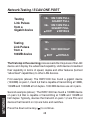
Network Testing / SCAN ONE PORT
Testing
Link Pulses
from a
Gigabit device
12> 10M 100M FULL
GIGABIT FULL
36> 10M 100M FULL
GIGABIT FULL
EXIT
DETAILS
Testing
Link Pulses
from a
100MB device
12>
36> 10M 100M HALF
EXIT
DETAILS
The first step in the scanning process reads the link pulses of the LAN
device and display the advertised capability. LAN devices broadcast
their capability in terms of speed, duplex and other features (termed
"advertised" capabilities) to other LAN devices.
NETWORKS
First example (above): The RWC1000 has found a gigabit device
(1000MB) on pairs 1,2 and 3,6 that is capable of transmitting at 10MB,
100MB and 1000MB at full duplex. 1000 MB devices use all 4 pairs.
Second example (above): The RWC1000 has found a 100MB device
on pairs 3,6 that is capable of transmitting at 10MB and 100MB at
half duplex. Typically, devices that transmit on pairs 1,2 are PCs and
devices that transmit on 3,6 are hubs and switches.
Press the down arrow key ( ) to continue.
48
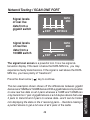
Network Testing / SCAN ONE PORT
Signal levels
of real live
data from a
gigabit switch
DATA
MIN
12 36 45 78
EXIT
DETAILS
Signal levels
of real live
data from a
100MB switch
DATA
MIN
36
EXIT
DETAILS
The signal level screen is a powerful tool. It is a live signal attenuation display. If the level is below the DATA MIN line, you may
experience faulty transmissions. If the signal is well above the DATA
MIN line, you have plenty of "headroom".
) key to continue.
The two examples shown shows off the differences between gigabit
devices and 10MB and 100MB devices.With a gigabit device it is possible
to view real live data on all 4 pairs whereas a 10MB and 100MB can
only transmit on 1 pair. A gigabit device is a full duplex device that uses
2 pairs to transmit and 2 pairs to receive data...and it can be tricked
into displaying the data on the 2 receiving pairs.... therefore making it
a perfect device to get a full view of all 4 pairs of the cable.
49
NETWORKS
Press the down arrow (
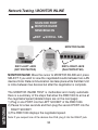
Network Testing / MONITOR INLINE
SCAN ONE PORT
MONITOR INLINE
SEND BEACON
EXIT
SCROLL SEL
MONITOR INLINE
RWC's RIGHT JACK
(PoE PROTECTED)
RWC's LEFT JACK
(NOT PROTECTED)
NETWORKS
MONITOR INLINE: Move the cursor to MONITOR INLINE and press
SELECT if you wish to view the negotiated results between two LAN
devices. Note: Data communication can take place while the Main Unit
is inline between two devices but after the negotiation is complete.
The MONITOR INLINE TEST is methodical and mostly automatic.
Here is a summary of the steps that allow the RWC1000 to arrive at
the negotiated speed (detailed steps are on the next page):
1) Plug in one PORT into the LEFT SOCKET of the RWC1000.
2) Pause for a few seconds and then plug the second PORT into the
RIGHT SOCKET.
3) The RWC1000 displays the negotiated speed.
Note: If you suspect one of the devices has PoE, plug it into the RIGHT jack.
50
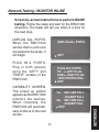
Network Testing / MONITOR INLINE
Screen-by-screen instructions to perform INLINE
testing. Follow the steps and wait for the RWC1000
directions. The tester will tell you when it is time for
the next step.
UNPLUG ALL PORTS.
When the RWC1000
senses that no ports are
connected to the tester, it
will begin.
UNPLUG ALL PORTS
EXIT
PLUG IN 2 PORTS.
Plug in both devices
using the "LEFT" and
"RIGHT" sockets of the
RWC1000.
PLUG-IN 2 PORTS
PC =>LEFT PLUG
HUB=> RIGHT PLUG
<POE PROTECTED>
EXIT
CAPABILITY SCREEN.
This screen (or similar)
appears as the RWC1000
monitors the devices.
When complete, the
RWC1000 will automatically continue to the next
screen.
51
NETWORKS
12> 10M 100M FULL
GIGABIT FULL
36> 10M 100M FULL
GIGABIT FULL
EXIT
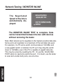
Network Testing / MONITOR INLINE
NEGOTIATED
GIGA BIT FD
The Negotiated
Speed of the link is
automatically displayed.
OK TO SEND DATA
MENU
The MONITOR INLINE TEST is complete. Data
can be transmitted between the two LAN devices
without removing the tester.
NETWORKS
Note: Most network ports negotiate to the highest possible data rate.
Some ports will negotiate to a maximum of the last data rate used.
For example, if a PC and a switch communicate at 100 MB/s and
a new gigabit switch is installed, the PC port may drag the switch
down to 100 MB/s, even if the PC is capable of gigabit data rate.
This may be solved by resetting the PC. Or use the SCAN ONE
PORT option to read and unstick the port. If in doubt, use the tester
to scan and unstick both ports, one at a time.
52
Network Testing / SEND BEACON
SEND BEACON
Locate cable drops by
lighting a link LED
SCAN ONE PORT
MONITOR INLINE
SEND BEACON
Scroll down and select SEND BEACON
EXIT
SCROLL SEL
USE RIGHT JACK
(PoE PROTECTED)
PORT BEACON: Use the Port Beacon to locate cable connections in
crowded areas. To activate the port beacon, move the cursor to PORT
BEACON and press SELECT. The Port Beacon is a link pulse that
the Main Unit sends to the receiving device every 3 seconds. The Port
Beacon causes the link LED to flash on the LAN device
allowing you to spot the connection
53
NETWORKS
PORT BEACON
Appendix A. Straight coupler
When installing or troubleshooting a LAN, you might need a straightthru cable coupler. The RWC1000's Main Unit jacks makes it easy. The
tester must be OFF to utilize this feature.
APPENDIX
Straight-thru
coupler
Note: If you suspect one of the devices is capable of sourcing PoE
voltage, connect the device to the RIGHT jack. The RIGHT jack
is protected from PoE voltage.
54
Appendix B. Ping and TCP/IP debugging tools
What is TCP/IP: TCP/IP is set of standards first developed by ARPA
(USA DOD’s Advance Research Projects Agency) that define how
information is routed over the Internet. And because of its internet
popularity, TCP/IP is the most popular protocol operating over
twisted pair cabling... and therefore is the most popular protocol
used by Ethernet (the standard for local area networking).
TCP/IP basics: TCP/IP has 4 layers: 1) The lowest layer is the
PHYSICAL layer that deals with cabling. 2) The next layer is the
INTERNET layer. This is the “IP” layer (internet protocol) and it
describes the assigning of an "ip" address to each data packet
that is transmitted (all data on the internet must have a destination
address associated with it and this is referred to as an "ip address").
The address can refer to a workstation on you local network or a
server on the internet thousands of miles away. 3) The next layer is
the TRANSPORT layer. Because data packets can travel through
networks and the Internet using many different routes, they will
not necessarily arrive in the same order as they were sent. There
needs to be a mechanism that reassembles the packets in the
proper sequence. This is the job of the “TCP” (transmission control
protocol) and it resides in this layer. 4) Layer 4, the highest layer
is the APPLICATION layer. This is where Ethernet and many other
software tools reside.
55
APPENDIX
Why learn about TCP/IP: Once the RWC1000 has established that
your cables and network devices are working at the hardware level
your next step is to checkout the software level of your network.
Understanding the basics of TCP/IP and gaining a familiarity with
your operating system's built-in network debugging tools helps you
diagnose and troubleshoot network problems at the software level.
APPENDIX
Because TCP/IP is so common, Windows and many UNIX systems
have built-in tools to help you debug TCP/IP network problems.
These debugging programs are executed at the command line
prompt of the operating system (see the end of this section for more
information about the command line).
ping
The most popular TCP/IP debugging program is called “ping” (after
the name given to the operation of submarine sonar devices). Like
the sonar, ping sends out a packet to an address that you specify
and waits for a reply. Although very simple to use, ping is extremely
powerful because it works at the IP level and often will respond even
when the higher level TCP layer cannot. As mentioned above, pinging capability is included with most systems and there are also many
shareware implementations.
USE: Determine if a workstation is connected to the network. Routers, servers and workstations are identified by an "ip" address and
possibly a "name". The ip address is a numeric string whose format
is referred to as "dotted decimal" (example: 192.168.0.0.). The
"name" can be any name given to a computer when it is installed or
an internet URL. The ability to use a name is provided by a server's
DNS (Domain Name Service). The DNS has a lookup table that
cross references ip addresses to names. If a DNS service is not
available you will need to use the ip address.
EXAMPLE OF USE: #1: I have problems connecting to the Byte
Brothers website from a workstation. I know the DNS name of the
website is “www.bytebrothers.com”. At the workstation’s Command
Prompt, enter “ping www.bytebrothers.com”. If connected, I will
receive back bytebrother.com's IP address (e.g. 207.115.64.64)
and the roundtrip time of my ping packet. #2) I am having a problem
with one of my workstations communicating to a server. I know the
server's ip address is 192.168.1.100. I enter “ping 192.168.1.100”
56
The Ping program has endless uses. Ping an address (as
above): If you get a response using the IP address but do not get
a response using the DNS address, there must be a problem with
the DNS system. If you suspect this, try another debugging program
"nslookup". On the command line enter nslookup followed by
the DNS name (enter nslookup www. bytebrothers.com) and see if
the IP address is displayed. If it is, your DNS appears to be working
correctly. Ping yourself: You can use the ping command to ping
yourself, either using your own IP address or what is known as
the loopback address. The loopback address is a special reserved
address that works on all systems:127.0.0.1 (enter ping 127.0.0.1).
If you would like to try pinging your own workstation address but do
not know it use the "ipconfig" command (see below). Pinging
yourself is the first test that should be conducted because if it fails
it most likely means that TCP/IP is not properly loaded on the
workstation. If it passes and you were using your own IP address
(not the loopback address), it confirms that you are the only one
on the network with that address. Ping your gateway: If you get
a response it means that the packets are making it to the router (a
gateway is a device on a network that serves as an entrance to
another network). On business LANs the gateway is generally the
router. In homes, the gateway is the ISP (internet service provider)
that connects the user to the internet.
Ping notes: If you want to ping another workstation or server and
57
APPENDIX
on the workstation’s Command Line. If the server is connected I will
receive a response to my ping. Note: It's easy to find a computer's
ip address. Go to the target computer (the one you wish to ping)
and on its command line enter "ipconfig". The ip address (and other
addresses will be displayed). More information on the ipconfig command can be found later in this section
you do not know its DNS name or IP address use ipconfig (below).
To learn all of the ping command’s option, enter ping /?.
APPENDIX
ipconfig
USE: Determine the IP address and other related information about
a workstation.
Enter ipconfig /? at the prompt to display the options possible with
this command. The two most common entries: ipconfig and ipconfig
/all.
EXAMPLES OF USE: I want to ping a remote server but I do not
know its ip address. Go to the server and at the command line
prompt enter “ipconfig”. The server's IP address will be displayed.
Return to the earlier workstation and perform the ping test to this
address.
tracert
USE: Determines how many router hops a packet took to reach its
destination. This can help determine why a network is slow (or not
functioning). Enter tracert /? at the prompt to display the options
possible with this command.
EXAMPLES OF USE: I want to determine how many routers
between my system and the ISO that services Byte Brothers. Enter
tracert followed by the name or IP address of the destination system
(enter www .bytebrothers.com).
Netstat
USE: Displays the current status of all listening TCP/IP ports. A TCP/
IP port is where applications connect to the server or workstation.
EXAMPLES OF USE: I would like to see how many applications are
tied to my system that use TCP/IP.
58
Additional information:
The web has many interesting articles on network troubleshooting
and also numerous sites that feature a glossary of terms. Use your
favorite search engine and search for Pinging, Pinging Devices, Network management, Network Monitoring Tools, Network Testing, etc.
59
APPENDIX
Executing troubleshooting programs from the command line
All of the programs discussed must be executed from the command
line of your operating system. To reach the command line on Windows 95 and 98 systems, click on START>PROGRAMS and Select
the MS DOS prompt. Then enter your command.
On Windows XP systems, click on START>PROGRAMS> and
select ACCESSORIES then COMMAND LINE. Then enter your
command.
On other systems select Run from the main menu and enter "cmd".
Then enter your command.
TO EXIT THE COMMAND LINE: Enter EXIT.
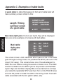
Appendix C. Examples of cable faults
A good cable: A cable that passes its first set of cable tests will
have summary screen similar to this:
LENGTH = 201'
DELAY 304NS PASS
SKEW 3NS PASS
Length / Timing
summary screen
of a good cable
EXIT
REVIEW
APPENDIX
Bad cable (Split pair): If errors are found, they will be displayed.
Here are some examples of screens with bad cables.
12>
36>
45>
78>
EXIT
Bad cable:
Split pairs
at 154'
154' SPLIT
154' SPLIT
330'
331'
DETAILS
The screen shows a 330’ cable with SPLIT pairs at 154’. If the cable
goes through a wiring closet, it is possible the SPLIT pairs are in the
closet (154’ away). This screen shows one of the advantages the
RWC has over testers costing thousands of dollars more. The RWC
shows the distance to the SPLIT pair to help locate it and facilitate
repair. High cost Certifiers display dBs of cross talk but do not help
you locate the repairable SPLIT pair fault. Turn on the TRACE tones
and use the probe to locate the cable in the wiring closet. Test each
cable associated with the link (patch cables, etc).
60
Bad cable (Near end short): The error is displayed as follows:
Bad cable:
Near End Short
12> ------- SHORT
36> 26' OPEN
45> 25' OPEN
78> 26' OPEN
EXIT
DETAILS
Bad cable:
Far End
Short
12>
36>
45>
78>
EXIT
27'
26'
25'
26'
SHORT
OPEN
OPEN
OPEN
DETAILS
OPENs in cable pairs generate errors in both in SKEW tests and
in wire map tests. The following example shows a 200’ cable with
a break in the middle on pair 78. The following is the first screen to
show a problem.
Bad cable:
Open
SKEW > 50 NS
LENGTH = 98'
DELAY 148 NS PASS
SKEW 150 NS FAIL
EXIT
DETAILS
Note there are two problems shown. The SKEW (difference in DELAY between pairs) is much greater than 50 NS. Another problem
61
APPENDIX
The SHORT on 12> is most likely at the connector (near end). If the
short is on the FAR END of the cable it would look like this:
is that the cable LENGTH is only shown as 98’. Press DETAILS
and continue the tests. All will become clear when cable map is
displayed. Here is a sample cable map.
APPENDIX
Bad cable:
Wire map
of open
pair
12> 199'
36> 202'
45> 202'
78> 98'
EXIT
= = = <12
= = = <36
= = = <45
= = = OPEN
DETAILS
The sample map clearly shows the problem. There is an OPEN at
98’ on pair 78>. The SKEW was so large because the timing pulses
travel about 200’ on pairs 12, 36, and 45, but only travel 98’ on pair
78. As always, retest cable after repairs are made.
During the wire map test you probably noticed that the indicator
lights on the REMOTE PROBE (connected to the far end of the
cable) continue to flash. This is another indication of a problem.
If a cable has a SHORT in the middle, the wire map looks like this:
Bad cable:
Wire map
of shorted
pair
12> 199'
36> 202'
45> 202'
78> 102'
EXIT
= = = <12
= = = <36
= = = <45
= = = SHORT
DETAILS
The RWC is both a RW CERTIFIER and troubleshooting tool.
It identifies the faults and gives you the distance to the OPENs,
SHORTs and SPLIT pairs.
62
Appendix D. Making a correct UTP cable
As mentioned above, twisted pair cable has separate pairs of wires
twisted together to minimize crosstalk. If a wiring error is made
and one pair of wire is “split” with another ("split pairs"), the excess
crosstalk will most likely keep the link from operating properly.
To make a proper cable, first choose a twisted pair cable that is
adequate for your application. For instance, CAT 5E cable for 100MB
and 1000MB applications. Use solid core wire when pulling inside a
wall. Use stranded cable ("patch cable") for jumpers.
●
Remove the outer jacket of the twisted pair cable exposing
about a 6" of wire on each end of the cable.
●
Each pair of wire must be twisted together (after crimping, the
wire should be twisted right up to the connector).
●
Do not make the number one wiring mistake: "Split pairs" (a wire
from one pair is swapped with a wire from another pair).
●
To minimize mistakes, use a standard color code throughout
your project. See the following page for the correct connector pin
numbers associated with each Base-T pair.
●
Use good quality connectors and tools
63
APPENDIX
Twisted Pair Cables: Unshielded twisted pair cable is used for
Base-T applications because it is inexpensive, easy to use and has
excellent noise cancelling capabilities. A minimum of two pairs of
twisted pair wire are required for each computer that connects to the
local area network:
●
One pair of twisted pair wire to transmit data.
●
One pair of twisted pair wire to receive data.
There are exceptions. 100 Base-T devices (called "T4") require 4
pairs of wires. Also, gigabit devices (1000MB) require 4 pair. In both
cases, 2 pair are used for transmit and 2 for receive.
RJ45 Connectors (sockets and plugs): The Base-T Standard
uses RJ45 sockets and plugs. The RJ45 socket has 8 pins. The pins
are numbered 1 to 8. Looking at the socket with insertion key facing
down, pin number 1 is to the left.
PLUGS
SOCKETS
1
8
8
8
1
1 1
8
APPENDIX
PIN NUMBERS
EIA/TIA 568B STRAIGHT THRU
PIN #
PIN# WIRE COLOR
1
1
Orange/White
2
2
Orange
3
3
Green/White
6
6
Green
4
4
Blue
5
5
Blue/White
7
7
Brown/White
8
8
Brown
Colors: The first color is the base color on the cable. Second color
is the stripe color of the cable. A straight-thru cable has identical
ends.
Note: The above color code is the most popular in use.
64
© 2010 Byte Brothers, Inc.
www.bytebrothers.com
Network Test and Certification
7003 132nd Place SE, Newcastle, WA 98059 USA
+1.425.917.8380 ● FAX +1.425.917.8379 ● [email protected]