1
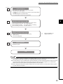
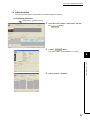
(2) Advanced setting
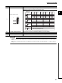
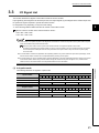
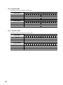
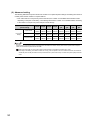
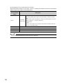
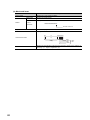
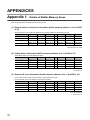
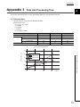
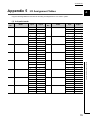
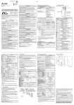
The following table lists the point mode and the number of occupied I/O points settings considering the number of
unused points and the number of occupied stations.
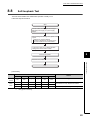
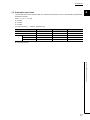
• Even if the number of occupied I/O points is the same, the number of controllable remote stations varies
depending on the point mode setting. The following table lists the number of connectable stations according
to the number of occupied I/O points and point mode settings.
Number of occupied I/O
points setting
4-point mode
Point mode
setting
8-point mode
16-point mode
16 pts.
32 pts.
48 pts.
64 pts.
128
256
512
1024
pts.
pts.
pts.
pts.
4
8
12
16
32
64
64
64
stations
stations
stations
stations
stations
stations
stations
stations
2
4
6
8
16
32
64
64
stations
stations
stations
stations
stations
stations
stations
stations
1
2
3
4
8
16
32
64
stations
stations
stations
stations
stations
stations
stations
stations
If the number of occupied I/O points is set larger than the maximum number of link points in the 4-point mode or 8-point
mode, the excessive I/O points cannot be used.
Ex. When the point mode is in the 4-point mode and the number of occupied I/O points is set to 1024
According to the setting, the master module can occupy 1024 I/O points in the CPU module. However, the number of
actual link points is 256 (the maximum link points when the 4-point mode is set). The rest of I/O points (768) cannot be
used.
34