1
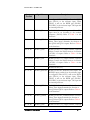
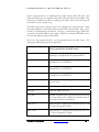
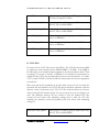
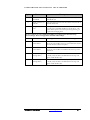
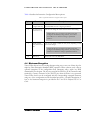
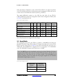
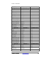
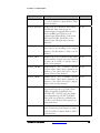
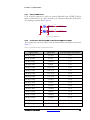
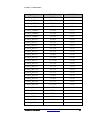
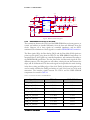
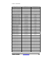
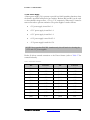
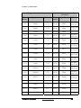
FPGA E
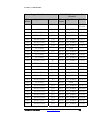
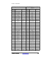
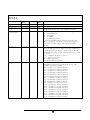
Start
Address
0x4C00_0004
0x4C00_0004
Read /
Write
R/W
Status Register
0x4C00_0008
0x4C00_0008
R
Existing FPGA
Register
0x4C00_0018
0x4C00_0018
R/W
External Host
Commands Register
End Address
Description
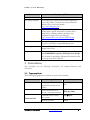
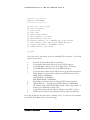
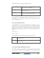
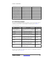
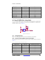
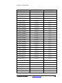
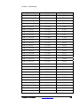
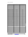
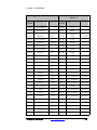
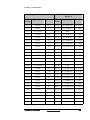
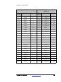
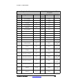
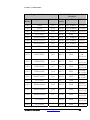
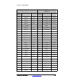
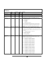
Write/Read register for MCU to issue the following commands:
0x1 – test all functionality
0x2 – test registers
0x5 – test FPGA interconnect
To issue a command the MCU must write one of the above
values to this register. The MCU can then poll this register to
check if the test is done (register will return all zeros when
finished)
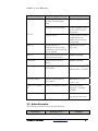
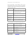
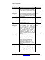
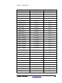
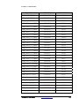
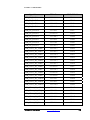
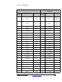
Read-only register - Status of commands and bus control:
Bits 16-18 must all be zero for MCU to issue any commands to
External Host Command Register. Status results can be read
after command register is cleared. The decode for the test results
is as follows:
Bit 0 – overall pass/fail (pass = 1, fail = 0)
Bit 1 – register test pass/fail
Bit 4 – interconnect test pass/fail
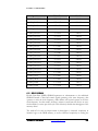
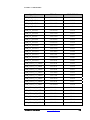
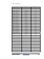
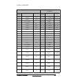
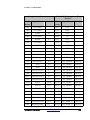
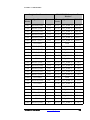
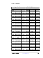
Contains information on what FPGAs are stuffed on the
DN6000k10 as well as what type of FPGAs they are. The
register has the following format:
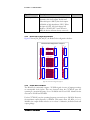
Bit 0 – 1 if FPGA A is stuffed, 0 otherwise
Bit 1 – 1 if FPGA B is stuffed, 0 otherwise
Bit 2 – 1 if FPGA C is stuffed, 0 otherwise
Bit 2 – 1 if FPGA D is stuffed, 0 otherwise
Bit 2 – 1 if FPGA E is stuffed, 0 otherwise
Bit 2 – 1 if FPGA F is stuffed, 0 otherwise
Bit 2 – 1 if FPGA G is stuffed, 0 otherwise
Bit 7 – 1 if FPGA H is stuffed, 0 otherwise
Bit 8 – 1 if FPGA I is stuffed, 0 otherwise
Bit 9 – 1 if FPGA A is 2vp100, 0 if 2vp70
Bit 10 – 1 if FPGA B is 2vp100, 0 if 2vp70
Bit 11 – 1 if FPGA C is 2vp100, 0 if 2vp70
Bit 12 – 1 if FPGA D is 2vp100, 0 if 2vp70
Bit 13 – 1 if FPGA E is 2vp100, 0 if 2vp70
Bit 14 – 1 if FPGA F is 2vp100, 0 if 2vp70
Bit 15 – 1 if FPGA G is 2vp100, 0 if 2vp70
Bit 16 – 1 if FPGA H is 2vp100, 0 if 2vp70
Bit 17 – 1 if FPGA I is 2vp100, 0 if 2vp70
179