1
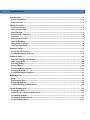
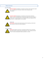
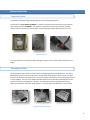
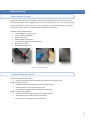
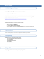
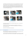
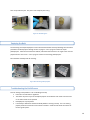
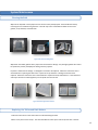
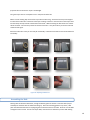
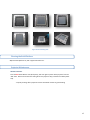
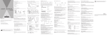
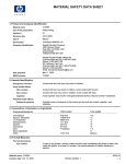
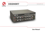
Projected Image Prototyping System User Manual 1 MSD P13552 Table Of Contents Introduction .......................................................................................................................................................... 3 System Capabilities..........................................................................................................................................................3 Saftey Overview ................................................................................................................................................................4 System Overview ................................................................................................................................................. 5 Projection System ............................................................................................................................................................5 Photopolymer Bath .........................................................................................................................................................5 Build Platform ...................................................................................................................................................................6 Electronics & Connections ............................................................................................................................................6 Enclosure.............................................................................................................................................................................6 Photopolymer Recipe .....................................................................................................................................................7 Material Handling ............................................................................................................................................................8 Photopolymer Storage....................................................................................................................................................8 Ordering Ingredients ......................................................................................................................................................8 Projector Setup .................................................................................................................................................... 9 Connecting the Projector ...............................................................................................................................................9 Troubleshooting the Projector....................................................................................................................................9 Software Guide .................................................................................................................................................. 10 LabVIEW Packages and Settings .............................................................................................................................. 10 Importing a Model ........................................................................................................................................................ 10 Selecting Settings .......................................................................................................................................................... 10 Slicing a Model................................................................................................................................................................ 10 Monitoring Build Progress......................................................................................................................................... 11 Stopping the Build......................................................................................................................................................... 11 Troubleshooting the Software.................................................................................................................................. 11 Building a Part .................................................................................................................................................. 12 Setup .................................................................................................................................................................................. 12 Removing the Part ........................................................................................................................................................ 13 Emptiying the Bath ....................................................................................................................................................... 14 Troubleshooting the Build Process ........................................................................................................................ 14 System Maintenance ....................................................................................................................................... 15 Cleaning the Bath .......................................................................................................................................................... 15 Replacing the Teflon and Bath Bottom................................................................................................................. 15 Assembling the Bath .................................................................................................................................................... 16 Cleaning the Build Platform ...................................................................................................................................... 17 Projector Maintenance ................................................................................................................................................ 17 2 Introduction The Projected Image Prototyping System enables the user to print 3D objects. This is accomplished using a light sensitive photopolymer that cures when exposed to high intensity light from the DLP projector. This process is fully automated and only requires user input to initialize the build process. System Capabilities The system is capable of printing 3D objects with the size limitation of a 4-inch (101.6mm) cube. Objects can be solid or hollow. This system is not able to produce parts that have features not directly connected to the object. Resolution is limited by the projectors pixel count and the chemistry of the photopolymer. It is recommended that test parts are printed multiple times to determine the correct settings for the detail and size desired. Figure I: Sample Parts 3 Saftey Overview PH OTOPOLYMER CONTACT HAZARD: Photopolymer is hazardous to human skin and membranes in liquid form. Use rubber gloves and proper ventilation when handling the liquid photopolymer. DISPOSAL HAZARD: Photopolymer is hazardous and must be fully cured before disposal. Curing is accomplished with a high intensity light source, direct sunlight is recommended. Cured photopolymer is not hazardous and may be disposed of in the general trash. Cured photopolymer is not recyclable. PROJECTOR CAUTION HOT: Projector bulb will be extremely hot when operating. Avoid contact with the bulb or lens until it has cooled completely. B UILD PLATFORM CAUTION: Build platform movement is automated and will pinch skin or extremities. Ensure upper cabinet is closed during entire build process. Do not attempt to remove the part or touch the build platform while the platform is in motion. 4 System Overview Projection System The projector unit produces high intensity light that cures the liquid photopolymer. The projector is a Sharp Model PG-MB60X. It contains a pressurized mercury lamp that can be replaced with a Sharp Lamp Unit AN-MB60LP. The projector is attached to the enclosure using four mounting screws located on the bottom of the projector. Avoid moving the projector while the system is in use. Figure II: Projector For more information on using and troubleshooting the projector refer to the Projector Setup Section on Page 9 Photopolymer Bath The photopolymer bath provides a reservoir for the uncured photopolymer during operation. The bath is filled before the print process is initiated and is manually filled during operation when required. The bath consists of an aluminum base that houses a clear acrylic window on the bottom covered with Teflon film and a series of gaskets. The clear acrylic window provides support for the Teflon film and allows light from the projector to reach the photopolymer in the bath. The Teflon film prevents cured photopolymer from adhering to the bottom of the bath during operation. The acrylic sheet and Teflon film are consumables. Figure III: Photopolymer Bath 5 Build Platform The build platform consists of a 4” square of sandblasted aluminum and is where the 3D object will adhere to during printing. Proper installation and setup of the build platform is important to the success of the machine. Figure IV: Build Platform Electronics & Connections The system’s motion is controlled using a stepper motor/lead screw assembly. These are in turn connected to the software through wiring to an Anaheim Automation Stepper Motor Driver Model DPY50611. The Anaheim Automation motor controller is connected to the user’s computer through a USB cable. Always completely power down the motor controller before disconnecting the stepper motor to prevent damage. Figure V: Controller and Power Strip A 120V power strip in the bottom of the enclosure provides power for the system. This power strip has receptacles to provide power to the projector and the motion controller system. There are additional receptacles for the user to connect the computer system, but this is not necessary. More information on controlling motion is available in the Software Guide Section on Page 10. More information on connecting the computer is available in the Building a Part Section on Page 12. Enclosure The enclosure is built primarily from sheet metal and 80/20. The upper section is enclosed in tinted Plexiglas. The lower door allows access to the power cords, projector, and motion controller. The upper door allows 6 access to the photopolymer bath and the build platform. During operation the upper section should remain closed. To aid in cooling of the projector and motion controller the lower section door needs to remain open to prevent damage to the projector and/or motion controller. Figure VI: Enclosure Photopolymer Recipe The visible light curable photopolymer recipe is as follows: 98 mL Hexanediol Diacrylate (CAS:13048-33-4) 2.00 g Phenylbis (2,4,6-Trimethylbenzoyl)-Phosphine Oxide (CAS:162881-26-7) Figure VII: Photopolymer Ingredients Use a balance and graduated cylinder to measure out the quantities needed for each ingredient. The photopolymer should be mixed in a beaker for 3 days prior to use. Cover the beaker containing the photopolymer with an opaque bag or box during mixing to prevent accidental curing. 7 Material Handling Always wear safety glasses and protective gloves when handling photopolymer mixture and/or ingredients. Use proper ventilation when mixing and handling photopolymer. A ventilation hood or air filtration system is recommended. Cover the material when not in use to block stray light sources from accidentally curing the photopolymer. Figure VIII: Material Handling Photopolymer Storage Store the photopolymer away from any visible light and properly contained in a chemical cabinet. Keep the photopolymer cool and dry. Do not store photopolymer in plastic containers. Figure IX: Photopolymer Storage Ordering Ingredients Ingredients can be ordered from Sigma Aldrich at: http://www.sigmaaldrich.com/united-states.html . 8 Projector Setup Connecting the Projector Confirm projector power cord is connected to the power strip located in the bottom of the enclosure. Ensure that the power strip is plugged into the nearest available power outlet. Turn the power strip on by using the power switch on the front. Turn the projector on by pressing the green ON button on the front of the projector. Attach the VGA and USB cable to the computer. Computer settings should be set to: “Extend Display to Projector” mode. Screen resolution of 800x600 Disable screen saver Disable computer sleep mode Lower projector brightness to lowest setting Black window borders Black desktop background Figure X: Connecting Projector Troubleshooting the Projector Projector is not projecting an image? Confirm connections are intact and make sure computer is in projection mode. Projector is not powering on? Confirm power strip is connected to an outlet properly and is on. Confirm projector is connected to the power strip. Check the power cable connection on the back of the projector. Image is not focused on platform? Keystone and Zoom settings can be used to recalibrate part size. Adjust the projector on the mounting bracket slides. Ensure quarts lens is attached to the projector lens. 9 Software Guide LabVIEW Packages and Settings The following LabVIEW packages need to be installed on the computer. NI-Vision Development Module NI-VISA The SMC60WIN v2.01 software and drivers from Anaheim Automation need to be installed for proper control of the stepper motor controller. This software is for the Anaheim Automation Stepper Motor Controller Model DPY50611. The direct link is: http://www.anaheimautomation.com/downloads/software/software.php The following files need to be located on the computer desktop Black image file named 00000.png Image files info1.png, info2.png, info3.png Replace LabVIEW code referencing Amy’sDesktop/info1 to the actual location of above file Importing a Model Load an stl file by specifying the location in the appropriate LabView program text box. Selecting Settings The following must be selected before a build is started: The units which the CAD model was exported in The layer thickness The base speed of the motor The cure time* The Visa Resource ** *For the Photopolymer described in this manual a cure time of 3 seconds is recommended **VISA Resource should be set to COM4 on most units Slicing a Model Begin slicing the file and initiate the build process by clicking “START” 10 Monitoring Build Progress Progress can be monitored via the LabView GUI layer count and progress section. The next layer to print and the current layer are also displayed. Stopping the Build To stop motion engage the red emergency stop by pressing it down. The system will need to be reset before restarting the build. Figure XI: Estop Troubleshooting the Software Check the motion controller’s connection with the computer. Check the stl file for errors. Ensure that the emergency stop is not engaged 11 Building a Part Setup Check the Teflon film in the bottom of the bath. If the film is loose or damaged replace it before proceeding. See the Replacing Teflon and Bath Bottom section on page 15. The bath is installed with the two witness marks on the side facing the back of the enclosure. The front left corner and the back right corner receive a ¼-20 bolt that secures the bath to the machine during operation. Before tightening these bolts check that the bath is level with a small level on the bottom of the bath. To adjust levelness place washers under the corners to achieve a level bath bottom. Tighten the bolts with the appropriate wrench. Figure XII: Installing the Bath Ensure that the projector is not projecting an image. If needed cover the projector lens. Fill the bath to half full with the photopolymer. Follow proper handling instructions from page 8. Figure XIII: Cover Projector Lens 12 The build platform is attached with four ¼-20 bolts. Loosely attach the build platform with the two witness marks on top towards the rear; do not tighten the bolts. Jog the build platform down until it is touching the bottom of the bath. Make sure the photopolymer does not overflow the bath during this. When the build platform is just touching, jog the platform down a little more to provide adjustment of the build platform. Press down gently on the center of the build platform while tightening the bolts with a wrench. Use a crisscross pattern to tighten the bolts. Tighten the front right bolt first followed by the rear left then the front left and finishing with the rear right. Figure XIV: Installing Build Platform If you covered the projector check that it is not projecting an image and uncover it. If an image is being projected adjust the computer. Load the stl file to be printed and press the start button on the LabVIEW GUI. The process is now automated and requires no user input. Periodically check the photopolymer level in the bath and refill using a syringe when necessary. When the part is finished LabVIEW will automatically stop. Removing the Part When finished printing use the jog buttons to raise the build platform so that the printed object is out of the uncured photopolymer. Allow the object to drain for a few minutes. To detach the part from the build platform first remove the build platform from the machine. Use a putty knife or razor blade to remove the cured part from the build platform. It may take a significant amount of 13 force to separate the part. The part is now ready for post curing. Figure XV: Detaching Part Emptying the Bath The remaining uncured photopolymer can be reused and should be stored by following the instructions provided in the Photopolymer Storage section on page 8. Use a syringe to remove the liquid photopolymer. When the level becomes shallow, unbolt the bath and tilt it at an angle so the uncured polymer flows to one corner. Use a syringe to remove the remaining photopolymer. Place the bath assembly aside for cleaning. Figure XVI: Removing Photopolymer Troubleshooting the Build Process Part not sticking to the platform? Part not building correctly? Ensure all nuts and bolts are tightened. The Teflon may have a layer of cured photopolymer on the bottom and needs to be removed or the Teflon needs to be replaced. Photopolymer may be spoiled. Look closely to determine whether the build platform is moving correctly. If it is not moving properly check the connection to the motion controller. Check all mechanical connections of the liner guide system. 14 System Maintenance Cleaning the Bath Wipe out the bath with a clean paper towel to remove excess photopolymer. Disassemble the bath by removing the 12 ¼-20 bolts along the sides. The bath top is then removable and allows access to the gaskets, acrylic window, and Teflon film. Figure XVII: Disassembling Bath Wipe down the rubber gaskets with a paper towel and check for damage. Any damaged gaskets will need to be replaced to prevent photopolymer leaking onto the projector. Inspect the Teflon film for damage. If damaged it will need to be replaced. Follow the instructions in the section below on replacing the Teflon film. Inspect the acrylic window. If damage it will need to be replaced. Follow the instructions in the section below to replace the acrylic bath bottom. If the Teflon film and acrylic window are undamaged they can be wiped clean and reused. Figure XVIII: Damaged Bath Bottom Replacing the Teflon and Bath Bottom Follow the instructions in the section above on disassembling the bath. Obtain a new piece of clear acrylic. The sheet should be 6 inches square and be 1/8 inch thick. Remove 15 projective film and ensure the acrylic is undamaged. Using the acrylic sheet as a template to cut a new piece of Teflon film. Obtain a roll of masking tape and cut four strips about 5 inches long. Attach the first strip to the edge of one side of the Teflon film so that half of the tape is sticking to the film. Place the film on the acrylic sheet and then wrap the tape around to the bottom of the sheet. While stretching the film attach it to another side of the sheet. Continue this process for all sides of the film. It may be necessary to remove sides and stretch the film again. When the Teflon film is taut you are ready for reassembly. Follow the instructions in the section below for reassembly. Figure XIX: Replacing Bath Bottom Assembling the Bath Starting with the aluminum bath base, arrange the bottom gasket in the base. Place the Teflon/acrylic assembly into the base with the Teflon film facing up. Place the remaining gasket on top of this. Now place the aluminum bath base on top aligning the two witness marks on the sides. Place the 12 ¼-20 bolts and tighten with a wrench. Do not over torque bolts; minimal force is sufficient to prevent bath leaking. 16 Figure XX: Reassembling Bath Cleaning the Build Platform Wipe the build platform dry with a paper towel after use. Projector Maintenance PROPER SH UTOFF Press the Red Power Button once (brief pause), and once again to power down projector from the “ON” state. Wait 5-10 minutes until cooling fan for the projector stops, and then turn off the power strip. * Properly shutting off the projector ensures the bulb life remains in good standing. 17