1
UM0857
User manual
Smart monitoring system STEVAL-IFS014V1
and STEVAL-IFS015V1, based on the STM32x
Introduction
This document explains the functioning of the "smart monitoring system" and also serves as
a quick reference manual to operate the system. The smart monitoring system works on
ZigBee® wireless technology and measures temperature, humidity and light intensity of 9
remote and different locations simultaneously. The system also demonstrates the wireless
control of home appliances and can serve as a basis for many new systems.
The objective of this demonstration board is to design a complete system which
demonstrates the effectiveness of low data rate wireless solutions from ST in automating
various measurements for weather parameters. This system can be further interfaced to
take an appropriate action based on the parameters being monitored. The system can very
easily be modified to control various household appliances by suitable additional hardware.
This system uses various devices, the most relevant are the STM32x (microcontroller),
SPZB260 (ZigBee® device), LIS331DLH (MEMS), STMPE811 (touchscreen controller),
STLM20 (temperature sensor) and various power supply components along with the battery
charger. The system has been designed taking future expandability into consideration.
The system can be powered up using:
■
External power supply
■
3.7 V Li-Ion battery
To summarize, the key features of the system are:
January 2010
■
Wireless network
■
Monitoring of weather parameters (temperature, humidity, light intensity)
■
Wireless light control application
■
Node movement and simultaneous node movement detection
■
Various weather warning configurations and alarm messages
■
TFT display with touchscreen
■
Real-time clock along with alarm configurations
■
Data logging for more than one year
■
GUI for data reading, saving and analysis using graphs
■
Power management system
■
Battery charging capability
■
Embedded in-circuit programming capability using JTAG
Doc ID 16752 Rev 1
1/66
www.st.com
Contents
UM0857
Contents
1
2
3
2/66
System features . . . . . . . . . . . . . . . . . . . . . . . . . . . . . . . . . . . . . . . . . . . . . 7
1.1
Wireless network . . . . . . . . . . . . . . . . . . . . . . . . . . . . . . . . . . . . . . . . . . . . 7
1.2
Single node movement detection . . . . . . . . . . . . . . . . . . . . . . . . . . . . . . . . 8
1.3
Simultaneous node movement detection . . . . . . . . . . . . . . . . . . . . . . . . . . 8
1.4
Weather alarm conditions . . . . . . . . . . . . . . . . . . . . . . . . . . . . . . . . . . . . . . 8
1.5
Light control application . . . . . . . . . . . . . . . . . . . . . . . . . . . . . . . . . . . . . . . 9
1.6
Data logging . . . . . . . . . . . . . . . . . . . . . . . . . . . . . . . . . . . . . . . . . . . . . . . . 9
1.7
User interface . . . . . . . . . . . . . . . . . . . . . . . . . . . . . . . . . . . . . . . . . . . . . . . 9
1.7.1
TFT display . . . . . . . . . . . . . . . . . . . . . . . . . . . . . . . . . . . . . . . . . . . . . . . 9
1.7.2
Touchscreen . . . . . . . . . . . . . . . . . . . . . . . . . . . . . . . . . . . . . . . . . . . . . . 9
1.7.3
Buzzer . . . . . . . . . . . . . . . . . . . . . . . . . . . . . . . . . . . . . . . . . . . . . . . . . . . 9
1.7.4
LEDs . . . . . . . . . . . . . . . . . . . . . . . . . . . . . . . . . . . . . . . . . . . . . . . . . . . 10
1.7.5
Menu . . . . . . . . . . . . . . . . . . . . . . . . . . . . . . . . . . . . . . . . . . . . . . . . . . . 10
1.8
Graphical user interface . . . . . . . . . . . . . . . . . . . . . . . . . . . . . . . . . . . . . . 10
1.9
Clock and alarm feature . . . . . . . . . . . . . . . . . . . . . . . . . . . . . . . . . . . . . . 10
1.10
Powering the system . . . . . . . . . . . . . . . . . . . . . . . . . . . . . . . . . . . . . . . . 10
Getting started . . . . . . . . . . . . . . . . . . . . . . . . . . . . . . . . . . . . . . . . . . . . . 11
2.1
System requirements . . . . . . . . . . . . . . . . . . . . . . . . . . . . . . . . . . . . . . . . 11
2.2
System content . . . . . . . . . . . . . . . . . . . . . . . . . . . . . . . . . . . . . . . . . . . . . 11
2.3
Hardware installation . . . . . . . . . . . . . . . . . . . . . . . . . . . . . . . . . . . . . . . . 11
2.4
Powering up the system . . . . . . . . . . . . . . . . . . . . . . . . . . . . . . . . . . . . . . 15
System operation . . . . . . . . . . . . . . . . . . . . . . . . . . . . . . . . . . . . . . . . . . 16
3.1
Starting up the system . . . . . . . . . . . . . . . . . . . . . . . . . . . . . . . . . . . . . . . 16
3.2
Establishing the network . . . . . . . . . . . . . . . . . . . . . . . . . . . . . . . . . . . . . 17
3.3
Seeing the parameters of a specific node . . . . . . . . . . . . . . . . . . . . . . . . 18
3.4
Data logging . . . . . . . . . . . . . . . . . . . . . . . . . . . . . . . . . . . . . . . . . . . . . . . 19
3.5
Alarm system . . . . . . . . . . . . . . . . . . . . . . . . . . . . . . . . . . . . . . . . . . . . . . 20
3.5.1
Threshold crossing of weather parameters . . . . . . . . . . . . . . . . . . . . . . 20
3.5.2
Node movement . . . . . . . . . . . . . . . . . . . . . . . . . . . . . . . . . . . . . . . . . . . 20
3.5.3
Simultaneous node movement . . . . . . . . . . . . . . . . . . . . . . . . . . . . . . . 21
Doc ID 16752 Rev 1
UM0857
4
Contents
6
7
8
Low battery and battery recovery . . . . . . . . . . . . . . . . . . . . . . . . . . . . . 22
3.5.5
Clock alarm . . . . . . . . . . . . . . . . . . . . . . . . . . . . . . . . . . . . . . . . . . . . . . 22
Description of the STEVAL-IFS014V1 (smart monitoring station) . . . 23
4.1
Components of the sensor data screen . . . . . . . . . . . . . . . . . . . . . . . . . . 23
4.2
Dedicated symbols for important actions . . . . . . . . . . . . . . . . . . . . . . . . . 23
4.3
Menu . . . . . . . . . . . . . . . . . . . . . . . . . . . . . . . . . . . . . . . . . . . . . . . . . . . . 24
4.4
5
3.5.4
4.3.1
USB mode . . . . . . . . . . . . . . . . . . . . . . . . . . . . . . . . . . . . . . . . . . . . . . . 25
4.3.2
About . . . . . . . . . . . . . . . . . . . . . . . . . . . . . . . . . . . . . . . . . . . . . . . . . . . 25
4.3.3
Switching the lamp on or off (light application) . . . . . . . . . . . . . . . . . . . 25
4.3.4
Setting the system time . . . . . . . . . . . . . . . . . . . . . . . . . . . . . . . . . . . . . 25
4.3.5
Setting the clock alarm . . . . . . . . . . . . . . . . . . . . . . . . . . . . . . . . . . . . . 26
4.3.6
Setting the various warning alarms . . . . . . . . . . . . . . . . . . . . . . . . . . . . 27
4.3.7
No-display mode (power saving) . . . . . . . . . . . . . . . . . . . . . . . . . . . . . . 27
4.3.8
System restore . . . . . . . . . . . . . . . . . . . . . . . . . . . . . . . . . . . . . . . . . . . . 27
Meaning of navigational icons . . . . . . . . . . . . . . . . . . . . . . . . . . . . . . . . . 28
Description of the STEVAL-IFS015V1 (smart monitoring node) . . . . . 29
5.1
Components of default display screen . . . . . . . . . . . . . . . . . . . . . . . . . . . 29
5.2
Other messages . . . . . . . . . . . . . . . . . . . . . . . . . . . . . . . . . . . . . . . . . . . . 29
5.3
JTAG connectivity . . . . . . . . . . . . . . . . . . . . . . . . . . . . . . . . . . . . . . . . . . . 30
Additional setup information . . . . . . . . . . . . . . . . . . . . . . . . . . . . . . . . . 31
6.1
Complete example of menu navigation of STEVAL-IFS014V1 . . . . . . . . 31
6.2
Factory default values . . . . . . . . . . . . . . . . . . . . . . . . . . . . . . . . . . . . . . . 34
6.3
LEDs . . . . . . . . . . . . . . . . . . . . . . . . . . . . . . . . . . . . . . . . . . . . . . . . . . . . 35
6.4
Battery connection . . . . . . . . . . . . . . . . . . . . . . . . . . . . . . . . . . . . . . . . . . 35
6.4.1
Battery connection - STEVAL-IFS014V1 . . . . . . . . . . . . . . . . . . . . . . . . 36
6.4.2
Battery connection - STEVAL-IFS015V1 . . . . . . . . . . . . . . . . . . . . . . . . 40
Schematics and bill of material . . . . . . . . . . . . . . . . . . . . . . . . . . . . . . . 46
7.1
Schematic and bill of material of STEVAL-IFS014V1 . . . . . . . . . . . . . . . . 46
7.2
Schematic and bill of material of STEVAL-IFS015V1 . . . . . . . . . . . . . . . . 57
Revision history . . . . . . . . . . . . . . . . . . . . . . . . . . . . . . . . . . . . . . . . . . . 65
Doc ID 16752 Rev 1
3/66
List of tables
UM0857
List of tables
Table 1.
Table 2.
Table 3.
Table 4.
4/66
Parameters of ZigBee network for smart monitoring system . . . . . . . . . . . . . . . . . . . . . . . . 7
Bill of material of STEVAL-IFS014V1 . . . . . . . . . . . . . . . . . . . . . . . . . . . . . . . . . . . . . . . . . 51
Bill of material of STEVAL-IFS015V1 . . . . . . . . . . . . . . . . . . . . . . . . . . . . . . . . . . . . . . . . . 60
Document revision history . . . . . . . . . . . . . . . . . . . . . . . . . . . . . . . . . . . . . . . . . . . . . . . . . 65
Doc ID 16752 Rev 1
UM0857
List of figures
List of figures
Figure 1.
Figure 2.
Figure 3.
Figure 4.
Figure 5.
Figure 6.
Figure 7.
Figure 8.
Figure 9.
Figure 10.
Figure 11.
Figure 12.
Figure 13.
Figure 14.
Figure 15.
Figure 16.
Figure 17.
Figure 18.
Figure 19.
Figure 20.
Figure 21.
Figure 22.
Figure 23.
Figure 24.
Figure 25.
Figure 26.
Figure 27.
Figure 28.
Figure 29.
Figure 30.
Figure 31.
Figure 32.
Figure 33.
Figure 34.
Figure 35.
Figure 36.
Figure 37.
Figure 38.
Figure 39.
Figure 40.
Figure 41.
Figure 42.
Figure 43.
Figure 44.
Figure 45.
Figure 46.
Figure 47.
Smart monitoring station (STEVAL-IFS014V1) - front view . . . . . . . . . . . . . . . . . . . . . . . . 12
Smart monitoring station (STEVAL-IFS014V1) - side view. . . . . . . . . . . . . . . . . . . . . . . . . 12
Smart monitoring station (STEVAL-IFS014V1) - back view . . . . . . . . . . . . . . . . . . . . . . . . 13
Smart monitoring node (STEVAL-IFS015V1) - front view. . . . . . . . . . . . . . . . . . . . . . . . . . 13
Smart monitoring node (STEVAL-IFS015V1) - side view . . . . . . . . . . . . . . . . . . . . . . . . . . 14
Smart monitoring node (STEVAL-IFS015V1) - back view . . . . . . . . . . . . . . . . . . . . . . . . . 14
Welcome screens of STEVAL-IFS014V1 . . . . . . . . . . . . . . . . . . . . . . . . . . . . . . . . . . . . . . 16
Initial data screen . . . . . . . . . . . . . . . . . . . . . . . . . . . . . . . . . . . . . . . . . . . . . . . . . . . . . . . . 16
Newly joined node . . . . . . . . . . . . . . . . . . . . . . . . . . . . . . . . . . . . . . . . . . . . . . . . . . . . . . . 17
Assign node number . . . . . . . . . . . . . . . . . . . . . . . . . . . . . . . . . . . . . . . . . . . . . . . . . . . . . . 17
Sensor data screen with one active node . . . . . . . . . . . . . . . . . . . . . . . . . . . . . . . . . . . . . . 18
Sensor data screen with more than one active node . . . . . . . . . . . . . . . . . . . . . . . . . . . . . 18
Selecting the node to see the parameters . . . . . . . . . . . . . . . . . . . . . . . . . . . . . . . . . . . . . 19
Warning messages . . . . . . . . . . . . . . . . . . . . . . . . . . . . . . . . . . . . . . . . . . . . . . . . . . . . . . . 20
Node movement - alarm message . . . . . . . . . . . . . . . . . . . . . . . . . . . . . . . . . . . . . . . . . . . 21
Simultaneous node movement of nodes 2, 4 and 5 caused simultaneous movement
detection . . . . . . . . . . . . . . . . . . . . . . . . . . . . . . . . . . . . . . . . . . . . . . . . . . . . . . . . . . . . . . . 21
Sensor data screen. . . . . . . . . . . . . . . . . . . . . . . . . . . . . . . . . . . . . . . . . . . . . . . . . . . . . . . 23
Dedicated icons for various actions . . . . . . . . . . . . . . . . . . . . . . . . . . . . . . . . . . . . . . . . . . 24
Menu details . . . . . . . . . . . . . . . . . . . . . . . . . . . . . . . . . . . . . . . . . . . . . . . . . . . . . . . . . . . . 24
Configured clock alarm indication . . . . . . . . . . . . . . . . . . . . . . . . . . . . . . . . . . . . . . . . . . . . 26
Details of data screen of STEVAL-IFS015V1 . . . . . . . . . . . . . . . . . . . . . . . . . . . . . . . . . . . 29
Various other message screens of STEVAL-IFS015V1 . . . . . . . . . . . . . . . . . . . . . . . . . . . 30
Selecting “MENU” using stylus . . . . . . . . . . . . . . . . . . . . . . . . . . . . . . . . . . . . . . . . . . . . . . 31
Menu . . . . . . . . . . . . . . . . . . . . . . . . . . . . . . . . . . . . . . . . . . . . . . . . . . . . . . . . . . . . . . . . . . 31
“SETTINGS” menu . . . . . . . . . . . . . . . . . . . . . . . . . . . . . . . . . . . . . . . . . . . . . . . . . . . . . . . 32
“CLOCK” menu . . . . . . . . . . . . . . . . . . . . . . . . . . . . . . . . . . . . . . . . . . . . . . . . . . . . . . . . . . 32
“SYSTEM TIME” - 1 . . . . . . . . . . . . . . . . . . . . . . . . . . . . . . . . . . . . . . . . . . . . . . . . . . . . . . 32
“SYSTEM TIME” - 2 . . . . . . . . . . . . . . . . . . . . . . . . . . . . . . . . . . . . . . . . . . . . . . . . . . . . . . 33
“SYSTEM TIME” - 3 . . . . . . . . . . . . . . . . . . . . . . . . . . . . . . . . . . . . . . . . . . . . . . . . . . . . . . 33
“SET SYSTEM TIME” - 4 . . . . . . . . . . . . . . . . . . . . . . . . . . . . . . . . . . . . . . . . . . . . . . . . . . 34
“SET SYSTEM DATE” . . . . . . . . . . . . . . . . . . . . . . . . . . . . . . . . . . . . . . . . . . . . . . . . . . . . 34
Dimensions of Li-Ion battery . . . . . . . . . . . . . . . . . . . . . . . . . . . . . . . . . . . . . . . . . . . . . . . . 35
Back of STEVAL-IFS014V1 and screwdriver . . . . . . . . . . . . . . . . . . . . . . . . . . . . . . . . . . . 36
Removal of rubber pads . . . . . . . . . . . . . . . . . . . . . . . . . . . . . . . . . . . . . . . . . . . . . . . . . . . 36
Removal of screws . . . . . . . . . . . . . . . . . . . . . . . . . . . . . . . . . . . . . . . . . . . . . . . . . . . . . . . 36
Front of STEVAL-IFS014V1 . . . . . . . . . . . . . . . . . . . . . . . . . . . . . . . . . . . . . . . . . . . . . . . . 37
Opening the top cover . . . . . . . . . . . . . . . . . . . . . . . . . . . . . . . . . . . . . . . . . . . . . . . . . . . . 37
Removing the cover of double-sided tape for battery placement . . . . . . . . . . . . . . . . . . . . 37
Battery correctly placed . . . . . . . . . . . . . . . . . . . . . . . . . . . . . . . . . . . . . . . . . . . . . . . . . . . 38
Battery soldering . . . . . . . . . . . . . . . . . . . . . . . . . . . . . . . . . . . . . . . . . . . . . . . . . . . . . . . . . 38
Checking that the battery connection is correct . . . . . . . . . . . . . . . . . . . . . . . . . . . . . . . . . 38
Closing the top cover of the case . . . . . . . . . . . . . . . . . . . . . . . . . . . . . . . . . . . . . . . . . . . . 39
Tightening the screws . . . . . . . . . . . . . . . . . . . . . . . . . . . . . . . . . . . . . . . . . . . . . . . . . . . . . 39
3 V coin-type CR2032 battery insertion for RTC power backup . . . . . . . . . . . . . . . . . . . . . 40
Back of STEVAL-IFS015V1 and screwdriver . . . . . . . . . . . . . . . . . . . . . . . . . . . . . . . . . . . 40
Removal of rubber pads . . . . . . . . . . . . . . . . . . . . . . . . . . . . . . . . . . . . . . . . . . . . . . . . . . . 40
Removal of screws . . . . . . . . . . . . . . . . . . . . . . . . . . . . . . . . . . . . . . . . . . . . . . . . . . . . . . . 41
Doc ID 16752 Rev 1
5/66
List of figures
Figure 48.
Figure 49.
Figure 50.
Figure 51.
Figure 52.
Figure 53.
Figure 54.
Figure 55.
Figure 56.
Figure 57.
Figure 58.
Figure 59.
Figure 60.
Figure 61.
Figure 62.
Figure 63.
Figure 64.
Figure 65.
Figure 66.
6/66
UM0857
Front of STEVAL-IFS015v1 . . . . . . . . . . . . . . . . . . . . . . . . . . . . . . . . . . . . . . . . . . . . . . . . 41
Removal of top cover of the case . . . . . . . . . . . . . . . . . . . . . . . . . . . . . . . . . . . . . . . . . . . . 41
Removing the LCD . . . . . . . . . . . . . . . . . . . . . . . . . . . . . . . . . . . . . . . . . . . . . . . . . . . . . . . 42
Removing the cover of double-sided tape for battery placement . . . . . . . . . . . . . . . . . . . . 42
Battery correctly placed . . . . . . . . . . . . . . . . . . . . . . . . . . . . . . . . . . . . . . . . . . . . . . . . . . . 43
Soldering the battery. . . . . . . . . . . . . . . . . . . . . . . . . . . . . . . . . . . . . . . . . . . . . . . . . . . . . . 43
Checking that the battery connections are correct . . . . . . . . . . . . . . . . . . . . . . . . . . . . . . . 43
Applying the LCD and closing the top cover of case . . . . . . . . . . . . . . . . . . . . . . . . . . . . . 44
Tightening the case with screws . . . . . . . . . . . . . . . . . . . . . . . . . . . . . . . . . . . . . . . . . . . . . 44
Applying the rubber pads and STEVAL-IFS015V1 powered up with battery . . . . . . . . . . . 45
3 V coin-type CR2032 battery insertion for RTC power backup . . . . . . . . . . . . . . . . . . . . . 45
Sheet 1 of schematic of STEVAL-IFS014V1 . . . . . . . . . . . . . . . . . . . . . . . . . . . . . . . . . . . 46
Sheet 2 of schematic of STEVAL-IFS014V1 . . . . . . . . . . . . . . . . . . . . . . . . . . . . . . . . . . . 47
Sheet 3 of schematic of STEVAL-IFS014V1 . . . . . . . . . . . . . . . . . . . . . . . . . . . . . . . . . . . 48
Sheet 4 of schematic of STEVAL-IFS014V1 . . . . . . . . . . . . . . . . . . . . . . . . . . . . . . . . . . . 49
Sheet 5 of schematic of STEVAL-IFS014V1 . . . . . . . . . . . . . . . . . . . . . . . . . . . . . . . . . . . 50
Sheet 1 of schematic of STEVAL-IFS015V1 . . . . . . . . . . . . . . . . . . . . . . . . . . . . . . . . . . . 57
Sheet 2 of schematic of STEVAL-IFS015V1 . . . . . . . . . . . . . . . . . . . . . . . . . . . . . . . . . . . 58
Sheet 3 of schematic of STEVAL-IFS015V1 . . . . . . . . . . . . . . . . . . . . . . . . . . . . . . . . . . . 59
Doc ID 16752 Rev 1
UM0857
1
System features
System features
The "smart monitoring system" has been designed and developed to give the user a number
of original features which make this system unique. The system is comprised of one smart
monitoring station (STEVAL-IFS014V1) and a maximum of 8 different smart monitoring
nodes (STEVAL-IFS015V1). The smart monitoring station and all the nodes make a
wireless STAR network and all the nodes communicate with the smart station using ZigBee
protocol. The smart station is a handheld device and can be carried by the user from one
place to another. Also the size of the smart monitoring node is small and can be placed
anywhere.
1.1
Wireless network
The smart monitoring station (STEVAL-IFS014V1) behaves as the coordinator of the
ZigBee network and develops the network with a predefined network ID. The smart
monitoring node (STEVAL-IFS015V1) can connect to the network as the end device. At any
time the complete network can have a maximum of 8 nodes, and the weather parameters of
all the nodes can be seen at the smart station along with those of the smart station.
The user can assign the application node numbers to the nodes which are connected during
the system installation. This gives the user the freedom to assign a specific number to the
connected node and place it anywhere.
Some of the key features of the wireless network are as follows:
●
The system network supports one smart station (STEVAL-IFS014V1) and a maximum
of 8 different nodes (STEVAL-IFS015V1)
●
The user can assign the node number one at a time to the nodes being joined to the
system
●
Whenever a node is switched off or gets out of range, the system detects its absence
and after ~1 minute, this node displays the message "node left"
●
If a node is switched off or gets out of range and comes back, the system detects it and
this node gets its previous user-assigned ID again without any intervention from the
user
●
If, in a working network, the power of the smart station is turned off and is powered up
again, then after complete startup, the system itself recognizes all the previous active
nodes of the system and re-assigns them the user-assigned numbers without any
intervention from the user.
For the smart monitoring system, the following configurations of the ZigBee network have
been used.
Table 1.
Parameters of ZigBee network for smart monitoring system
Parameter
Value
Channel
26
Panid
0x01F0
Extended panid
{'H','W','M','S','_','S','T','M'}
Power
3
Doc ID 16752 Rev 1
7/66
System features
Table 1.
UM0857
Parameters of ZigBee network for smart monitoring system (continued)
Parameter
Value
profile_ID
0xAAAA
Cluster_ID
0x0045
Note:
Please note that these parameters have been chosen without any special consideration and
can be changed later, but they should be the same for STEVAL-IFS014V1 and STEVALIFS015V1.
1.2
Single node movement detection
The system also detects movement or vibration of the active nodes in which case the buzzer
sounds at the smart node and the smart station also receives this information. At the smart
station an alarm buzzer sounds along with a message on the TFT display.
The system also calibrates the node movement into five different levels and stores this data
along with the node number, severity level, date and time stamp. Node movement levels are
defined in a range from 1 to 5 where 1 is the lowest intensity and 5 is the highest intensity.
1.3
Simultaneous node movement detection
The system has the capability to detect the simultaneous movement of all the connected
nodes. The system detects simultaneous movement and sounds a buzzer alarm for the user
and displays the warning message on the TFT display. This information is also stored in the
data logging system along with the date and time stamp as “earthquake”.
Note:
In the GUI of the system, the simultaneous movement of nodes is designated as
“earthquake”.
Note:
Simultaneous movement detection is possible only when the nodes have joined the system
and are active, otherwise no earthquake detection is done as the smart station itself is a
handheld system.
1.4
Weather alarm conditions
The system has the capability to configure the various maximum and minimum threshold
values of the weather parameters of all the nodes connected to the system for the alarm
conditions. Each node can be configured for different values.
Whenever any alarm condition of any of the smart node is reached, an alarm signal is given
at the smart node as well as at the smart monitoring station.
The user can change the alarm conditions at any time through the smart monitoring station;
there is no need to restart the system or node.
8/66
Doc ID 16752 Rev 1
UM0857
1.5
System features
Light control application
The system demonstrates the application of wireless light control through which the user
can control the LED lamp of any active smart node (D1 of STEVAl-IFS05V1) through the
smart station.
This is just the demonstration of the wireless light control application and can be enlarged to
a wider level to control any electrical appliance.
1.6
Data logging
The system has a data logging system which can store the data of more than one year (two
values for each parameter of each node per day). The data logging system stores the
maximum and minimum values of all the parameters of all the active smart nodes (STEVALIFS015V1) and smart station (STEVAL-IFS014V1) of one day along with the time stamp.
The user can refer to the maximum and minimum value of any of the parameters of any of
the nodes of any date and the time when it happened.
It also stores the node movement data of all the nodes along with the severity level, date and
time stamp. So the user can view later which node was moved at which date and at what
time.
Similar to the node movement data, the system also stores the earthquake (simultaneous
movement of all active nodes) along with the severity level, date and time stamp.
Note:
In the present system, the earthquake severity level is not calculated and has been set to
minimum level 1.
1.7
User interface
The system has been provided with an interactive user interface with the features described
in the following sections.
1.7.1
TFT display
The smart station (STEVAL-IFS014V1) has been provided with a 2.4" color TFT display on
which all the data is displayed along with the various colored icons/symbols.
The smart node (STEVAl-IFS015V1) has been provided with a 122 X 32 graphical LCD
display.
1.7.2
Touchscreen
The smart station (STEVAL-IFS014V1) has a touchscreen with which the user can navigate
through the menu by just pressing the particular option displayed on the display. A beep
produced by the buzzer confirms every screen touch.
1.7.3
Buzzer
Both the smart station and node have been provided with a buzzer which is used for the
alarm conditions.
Doc ID 16752 Rev 1
9/66
System features
1.7.4
UM0857
LEDs
Both the smart station and node have been provided with four status LEDs and one LED
lamp (see Section 6.3).
1.7.5
Menu
Apart from all the hardware human interfaces, the system has been provided with a very
good and user-friendly menu with which the user can perform various actions and settings.
1.8
Graphical user interface
The system is provided with a very useful graphical user interface to read and analyze the
data logged in the system.
Some of the key features of the GUI are:
1.9
●
All the logged data can be read from the system within 2-3 seconds
●
The read data can be saved in the computer and can be analyzed at any time, if the
system is connected to the computer or not
●
The user can separate the data of the various nodes from any start and end date and
can save the data in a .csv file format (.csv is a standard file format which stands for
comma separated values. This file can be viewed using the software tool Microsoft
office Excel.)
●
The user can also plot the data in various graphs and can compare the data of the
various nodes with each other and also for different dates of one node
●
Graphs can be generated with various features to visualize the data in a proper way
●
The user can save the graphs as pictures and even print the graphs.
Clock and alarm feature
The system has a built-in real-time clock. The user has the flexibility to set the clock
time/date using the menu and the clock keeps running even when the system is not
powered up. The user can also set the clock alarm for the same day.
1.10
Powering the system
The system has multiple ways of powering up with key features:
10/66
●
Both the smart station (STEVAL-IFS014V1) and smart node (STEVAL-IFS015V1) can
be powered up using the USB power supply (5 V) or 3.7 V Li-Ion battery
●
The system has the capability to switch over from the external supply to battery backup
and vice versa by itself
●
When external USB power is available, the onboard battery starts charging and the
system itself operates using external power
●
The system has the capability to detect the low battery of the smart station (STEVALIFS014V1) as well as of the nodes (STEVAl-IFS015V1), and the information is
displayed as an alarm and indicator of a low battery.
Doc ID 16752 Rev 1
UM0857
Getting started
2
Getting started
2.1
System requirements
The system requires Li-Ion batteries (3.7 V, 1800 mAh) or suitable mini USB adaptors (5 V,
500 mA) for powering of the smart station (STEVAL-IFS014V1) and the node (STEVALIFS015V1).
2.2
System content
The complete system is comprised of the following:
●
●
Hardware
–
STEVAL-IFS014V1 (smart monitoring station), 1 USB cable and 1 stylus
–
Three STEVAL-IFS015V1 devices (smart monitoring nodes)
Software
–
●
GUI of the smart monitoring system
Documentation
–
User manual (this document)
Note:
The user should buy the STEVAL-IFS014V1 and STEVAL-IFS015V1 separately. These two
are different entities and together they comprise the smart monitoring system.
Note:
The smart monitoring system works as a standalone unit with either the STEVAL-IFS014V1
or STEVAL-IFS015V1. All the parameters are measured and displayed on the onboard
display. Adding one node to the smart station allows one to evaluate the wireless features
and the addition of two nodes would allow one to test the feature of simultaneous movement
of the nodes. Two additional quantities of the STEVAL-IFS015V1 are recommended only to
evaluate the complete system.
2.3
Hardware installation
Both the smart monitoring station (STEVAl-IFS014V1) and smart node (STEVAL-IFS015V1)
can be powered by an external USB adaptor (5 V, 500 mA) or mini USB cable or by using
the 3.7 V Li-Ion battery.
Doc ID 16752 Rev 1
11/66
Getting started
UM0857
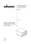
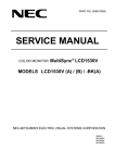
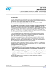
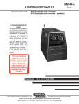
Figure 1.
Smart monitoring station (STEVAL-IFS014V1) - front view
!LARM,%$
,AMP,%$
(OLEFOR,$2
,IGHTDEPENDENT
RESISTOR
:IG"EENETWORK
,%$
!-V
The major components present on the smart monitoring station (STEVAL-IFS014V1) - front
view are (see Figure 1):
●
TFT display having built-in touchscreen
●
Light-dependent resistor (LDR) for measuring ambient light intensity
●
D2 - LED indicator for alarm
●
D1 - LED indicator for lamp
●
NW - LED indicator for ZigBee® activity
Figure 2.
Smart monitoring station (STEVAL-IFS014V1) - side view
-INI53"CONNECTOR
FOREXTERNALPOWERAND
53"COMMUNICATION
,%$INDICATING
BATTERYCHARGING
,%$INDICATING
BOARDPOWERSTATUS
0OWERSWITCHTO
/./&&THEPOWERSUPPLY
!-V
The major components present on the smart monitoring station (STEVAl-IFS014V1) - side
view are (see Figure 2):
12/66
●
USB - mini USB connector for power and USB connectivity
●
Power switch - used for switching the board power on or off
●
CH - LED indicator for battery charging
●
PW - LED indicator for board power
Doc ID 16752 Rev 1
UM0857
Getting started
Figure 3.
Smart monitoring station (STEVAL-IFS014V1) - back view
3TANDTOPLACEBOARDONTABLE
!-V
The smart monitoring station STEVAL-IFS014V1 includes a stand (see Figure 3 ).
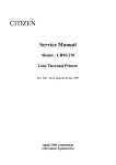
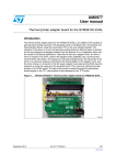
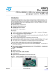
Figure 4.
Smart monitoring node (STEVAL-IFS015V1) - front view
,AMP,%$
!LARM,%$
:IG"EENETWORK
,%$
,%$INDICATING
BOARD
POWERSTATUS
(OLEFOR,$2
LIGHTDEPENDENTRESISTOR
'RAPHICAL,#$DISPLAY
X
,%$INDICATING
BATTERYCHARGING
!-V
The major components present on each smart monitoring node (STEVAL-IFS015V1) - front
view are (see Figure 4):
●
Graphical LCD
●
Light-dependent resistor (LDR) for measuring ambient light intensity
●
D1 - LED indicator for lamp
●
D2 - LED indicator for alarm
●
NW - LED indicator for ZigBee activity
●
CH - LED indicator for battery charging
●
PW - LED indicator for board power
Doc ID 16752 Rev 1
13/66
Getting started
UM0857
Figure 5.
Smart monitoring node (STEVAL-IFS015V1) - side view
-INI53"CONNECTORFOREXTERNAL
POWERAND53"COMMUNICATION
0OWERSWITCHTO
/./&&THEPOWERSUPPLY
!-V
The major components present on each smart monitoring node (STEVAL-IFS015V1) - side
view are (see Figure 5):
●
USB - mini USB connector for power
●
Power switch - used for switching board power on or off
Figure 6.
Smart monitoring node (STEVAL-IFS015V1) - back view
7ALLCLIP
!-V
The smart monitoring node (STEVAl-IFS015V1) has a clip to hang the board on the wall
(see Figure 6).
Note:
14/66
For a complete hardware description of the smart monitoring station (STEVAL-IFS014V1)
and smart monitoring node (STEVAL-IFS015V1), please contact your local
STMicroelectronics sales office.
Doc ID 16752 Rev 1
UM0857
2.4
Getting started
Powering up the system
Both the smart monitoring station (STEVAL-IFS014V1) and smart monitoring node
(STEVAL-IFS015V1) can be powered up using the USB power adaptor (5 V, 500 mA) or the
mini USB cable (through a computer/laptop) or by using the battery (3.7 V Li-ion). The
system uses the battery power only in case of unavailability of the external power supply.
The system itself switches from the external power supply to battery and vice versa.
The system also has the capability to charge the battery when the external power supply is
available at which time the system switches its power consumption from battery to mains
and the battery starts charging.
On both the smart monitoring station and smart monitoring node, there is a power switch
which is used to switch the supply on or off to the system.
There are two status LEDs:
●
Power LED (PW): This indicates if the system is on or off
●
Charging LED (CH): This indicates the charging status of the battery. If the battery is
being charged from the external power supply, then this LED glows. If the external
power supply is available but the battery is fully charged, then this LED is off.
Note:
If no battery is connected and the system is powered using the USB supply, then the
behavior of the charging LED 'CH' is unpredictable.
Note:
For information regarding battery insertion in the STEVAL-IFS014V1 and STEVALIFS015V1, please see Section 6.4.
Doc ID 16752 Rev 1
15/66
System operation
UM0857
3
System operation
3.1
Starting up the system
The following steps indicate system and network startup:
1.
Power on the smart monitoring station (STEVAL-IFS014V1) using the power switch and
the green LED (PW) glows, indicating that the station is powered up successfully.
2.
After a moment, welcome screens appear on the TFT display.
3.
After the welcome screens, a wait screen appears on the display indicating
"SCANNING NETWORK". The user should not do anything until the network scanning
is complete. After the scanning is complete, a screen indicating the text "NETWORK
SCANNING COMPLETED" appears for a short time.
Figure 7.
Welcome screens of STEVAL-IFS014V1
7ELCOMESCREEN
7ELCOMESCREEN
7AITSCREEN
!-V
4.
After all the above steps, the main sensor data screen appears on the display as shown
in Figure 8.
Figure 8.
Note:
16/66
Initial data screen
For details of the components of the display window see Section 4.1.
Doc ID 16752 Rev 1
UM0857
3.2
System operation
Establishing the network
Completion of the steps in Section 3.1 creates the network for the smart monitoring station
(STEVAL-IFS014V1). In order to join the different smart monitoring nodes (STEVALIFS015V1) to the network, the user should perform the following steps:
1.
After the data screen is displayed on STEVAL-IFS014V1, the user should power on one
of the smart nodes (STEVAL-IFS015V1) (for details see Section 5).
2.
A screen on the display of STEVAl-IFS014V1 appears indicating that a new node has
joined the system as shown in Figure 9.
Figure 9.
3.
Newly joined node
After a while, the user is asked to assign the node number to the newly joined node, as
shown in Figure 10.
Figure 10. Assign node number
4.
The user can assign the node number using the touchscreen by pressing the icons
displayed on the screen (to see the meaning of the various icons, see Section 4.4).
5.
As the node number is assigned to the joined node, the display returns to the default
data screen, but with the displayed node number which has joined the system. The
parameters of the node are displayed on the screen as shown in Figure 11.
Doc ID 16752 Rev 1
17/66
System operation
UM0857
Figure 11. Sensor data screen with one active node
6.
Similarly, the user can power up the various nodes (one at a time) and assign the
various node numbers to them. Accordingly, the SENSOR DATA screen of STEVALIFS014V1 is updated, displaying the various joined nodes on the left side of the main
screen as shown in Figure 12.
Figure 12. Sensor data screen with more than one active node
7.
The system does not allow the user to assign the same node number to two different
nodes which prompts an error message. The system does not exit the "ASSIGN NODE
NUMBER" screen until the user assigns the node number to the newly joined number.
Note:
It is recommended that no node should be switched on until the STEVAL-IFS014V1 shows
the default data screen after startup.
3.3
Seeing the parameters of a specific node
When the very first node joins the system, the system itself selects that particular node and
shows the various parameters of the node on the TFT display of the smart monitoring
station (STEVAL-IFS014V1). If more than one node is connected to the system, then the
user can select any of the connected nodes to display the various parameters on the sensor
data screen of the STEVAL-IFS014V1.
The user can select any particular node by simply pressing the node number displayed on
the screen using a stylus. The parameters of the selected node are displayed on the screen
along with that of the smart monitoring station.
18/66
Doc ID 16752 Rev 1
UM0857
System operation
Figure 13. Selecting the node to see the parameters
Note:
The user can see the parameters of only one node (STEVAL-IFS015V1)at a time along with
the smart monitoring station (STEVAL-IFS014V1) on the sensor data screen.
Note:
The parameters of the node and station are updated at regular intervals of time and the
response is not instantaneous. If an event occurs at the node/station, it can take several
seconds to be displayed. If the user wants to see the instantaneous response, he/she can
simply press any part of the screen and the data is updated.
3.4
Data logging
The smart monitoring station (SETVAL-IFS014V1) has the capability to log the data of all
the active nodes (STEVAL-IFS015V1) for more than one year and this data can be seen
using the GUI developed for the system.
Three types of data are logged in the system:
1.
Maximum and minimum values of weather parameters: the station stores the maximum
and minimum values of all the weather parameters of all the nodes including itself once
per day. These values are stored along with the time stamp. With this data the user can
know not only the values, but also at what time of day the various parameters of the
weather reached their maximum and minimum values. This data can be stored for more
than one year.
2.
Node movement data: the system stores the node movement data of all the active
nodes along with the severity level of the movement, date and time stamp.
3.
Simultaneous movement of all nodes / earthquake data: the system also stores the
information of simultaneous movement of all active nodes/ earthquake data along with
the date and time stamp.
All of the above data can be viewed using the GUI and by performing the following steps:
1.
Go to the "USB MODE" of the smart monitoring station (STEVAL-IFS014V1) (see
Section 4.3.1)
2.
Plug in the USB cable to the board and connect it to the computer which has the
installed GUI and driver for the smart monitoring system
3.
Operate the GUI and read the data logged in the smart monitoring station
4.
To exit the USB mode, remove the USB cable from the board and press the display
screen.
Doc ID 16752 Rev 1
19/66
System operation
Note:
3.5
UM0857
1
The GUI can read the data only from the smart monitoring station (STEVAL-IFS014V1).
USB communication is not available in the smart monitoring node (STEVAL-IFS015V1).
2
The GUI reads the data from the board only once at startup and then processes that data.
Once the file is read from the board, the board can be removed and can exit the USB mode.
3
As long as the station is in USB mode, all other operations are stopped. The station should
not be kept in USB mode for a long time after reading the file using the GUI to prevent losing
the wireless link and data.
Alarm system
The system has the capability to detect various alarm conditions and give indication to the
user. The system gives warnings for the following conditions.
3.5.1
Threshold crossing of weather parameters
The smart monitoring station and all the active nodes can be configured to display warnings
upon crossing the maximum or minimum threshold of any of the weather parameters.
Whenever any weather parameter of any node crosses the configured maximum or
minimum limit, then that node sounds an alarm. At the same time this information is
transferred to the smart monitoring station through ZigBee and an alarm sounds also at the
smart monitoring station along with the warning on the display (see Figure 14).
Figure 14. Warning messages
7ARNINGSCREENOF
34%6!,)&36
7ARNINGSCREENOF34%6!,)&36
!-V
All the nodes and the smart monitoring station function in this manner.
Note:
For displayed warnings, if the user acknowledges the alarm by pressing the screen of the
STEVAL-IFS014V1 when the warning is displayed on the screen, then the alarm does not
post again for some time (~15 minutes). During this time interval the user can remove the
cause of the alarm. If, after that time has passed the condition re-occurs, then the alarm is
displayed again.
3.5.2
Node movement
Whenever any active node of the system vibrates or moves from its place, an alarm sounds
at the node. At the same time, this information is transferred to the smart monitoring station
along with the severity level of the movement. At the smart monitoring station an alarm
sounds along with the alarm message on the display as shown in Figure 15.
20/66
Doc ID 16752 Rev 1
UM0857
System operation
Figure 15. Node movement - alarm message
.ODEMOVEMENTSCREENOF
34%6!,)&36
.ODEMOVEMENTSCREENOF34%6!,)&36
!-V
This information is also stored in the data logging system with the date and time stamp for
future reference.
3.5.3
Simultaneous node movement
The system has the capability to detect the simultaneous movement of all the active nodes
and sounds an alarm and displays a message on the screen as shown in Figure 16.
Figure 16. Simultaneous node movement of nodes 2, 4 and 5 caused simultaneous
movement detection
.ODEMOVEMENTSCREENOF34%6!,)&36
3IMULTANEOUSNODEMOVEMENTSCREENOF
34%6!,)&36
.ODEMOVEMENTSCREENOF34%6!,)&36
.ODEMOVEMENTSCREENOF34%6!,)&36
!-V
Note:
1
Simultaneous movement of all the active nodes of the system has been defined as
“earthquake” for the system when logging the data into the system, but simultaneous
movement of the nodes can also happen without an earthquake. The system is just
Doc ID 16752 Rev 1
21/66
System operation
UM0857
demonstrating the concept which has no relation with a real earthquake and has not been
tested using any vibration-producing system until now.
2
3.5.4
For the system to detect any simultaneous node movement, at least one node should be
active in the system.
Low battery and battery recovery
The system has the capability to detect a low battery of the smart monitoring station as well
as that of all the nodes. Whenever the system detects a low battery, a warning is displayed.
Also, on the data screen of the station (STEVAL-IFS014V1) the node number becomes red,
indicating the low battery of that particular node. Similar information is displayed on the data
screen of the node also (see Section 4.1 and 5.1).
When the battery is charged, the system detects the battery status and displays a message
on the screen and the node number becomes blue again.
Note:
3.5.5
1
When the battery value falls to 3.3 V, the board interprets this value as a low battery and the
user should charge the battery. To prevent total discharging of the battery, the board
switches off when the battery voltage falls to 2.5 V. The board shuts down after low-battery
detection in approximately 2 hours, but this time depends on the type and rating of the
battery being used.
2
Even after the system shuts down, the user should charge the battery within 8 hours
otherwise deep discharging can cause the permanent damage to the battery.
Clock alarm
The smart monitoring station has the capability to configure the clock alarm for the same
day. The alarm time should be greater than the current system time and when the system
time matches that of the configured alarm time, the system sounds an alarm and a picture of
a bell is displayed.
22/66
Doc ID 16752 Rev 1
UM0857
4
Description of the STEVAL-IFS014V1 (smart monitoring station)
Description of the STEVAL-IFS014V1 (smart
monitoring station)
The smart monitoring station (STEVAL-IFS014V1) acts as the coordinator for the ZigBee
network to which all the smart monitoring nodes (STEVAL-IFS015V1) are connected. In
addition to the network formation and parameter display, it is equipped with a very
interactive menu with which the user can perform various actions. In this section of the
document we explain in detail the smart monitoring station.
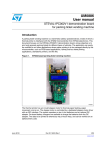
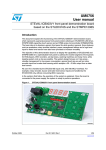
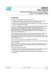
4.1
Components of the sensor data screen
Figure 17. Sensor data screen
3MARTNODE
PARAMETERS
3MARTSTATION
PARAMETERS
,OWBATTERYINDICATIONOFSMART
MONITORINGSTATION34%6!,)&36
!CTIVENODE
4EMPERATURE
#ENTIGRADE
!CTIVENODE
WITH
LOWBATTERY
(UMIDITY
RELATIVE
,IGHT
INTENSITY
.ODESNOT
CONNECTED
,IGHTLAMP
STATUS
.ODE34%6!,)&36
4.2
$ATE
!LARM
CONFIGURED
4IME
-ENU
!-V
Dedicated symbols for important actions
Several white colored icons are situated on the right side of the TFT display of the STEVALIFS014V1 which have been configured for important functions (see Figure 18). These
functions can also be performed using the menu options as explained earlier, but these
dedicated icons are available at any time irrespective of where the user is in the system.
Doc ID 16752 Rev 1
23/66
Description of the STEVAL-IFS014V1 (smart monitoring station)
UM0857
Figure 18. Dedicated icons for various actions
53"MODE
4&4BACKLIGHT
OFF
-ENU
%XITFROMMENU
!-V
Note:
These icons do not work when the system is in the "ASSIGN NODE NUMBER" screen.
4.3
Menu
The menu of the smart monitoring station has a hierarchical structure which is illustrated in
the figure below.
Figure 19. Menu details
24/66
Doc ID 16752 Rev 1
UM0857
Description of the STEVAL-IFS014V1 (smart monitoring station)
The menu options are explained in detail in the following sections.
4.3.1
USB mode
To get the data from the data logging system, the user has to go to the USB mode using the
menu option available.
The user can exit the USB mode by pressing the screen. The system exits the USB mode
and the default sensor data screen is displayed.
4.3.2
About
To obtain system information, the user can go to the “ABOUT” option of the menu. A screen
describing the details of the system is displayed. There are four screens for the “ABOUT”
option of the system and the user can navigate through these by touching the “NEXT” or
“BACK” symbol on the screen.
4.3.3
Switching the lamp on or off (light application)
To switch the lamp on or off, the user should perform the following steps:
1.
Go to “MENU/ LIGHTS’, following the menu options available (see Figure 19).
2.
Select the node number of the lamp to be controlled or “Node 0” for the smart
monitoring station. Use the “INC” icon to increase the node number and “SET” to select
the node number. Only the active nodes of the system are displayed when “INC” is
pressed
3.
After the node selection, the user is given options to switch the lamp on or off. The user
can select any option and the action is performed accordingly.
Note:
On the board, the lamp is indicated using an onboard LED. To control the actual lamp,
additional hardware is required and that hardware is not the part of the system provided.
4.3.4
Setting the system time
To set the system time, the user should perform the following steps:
Note:
1.
Go to "SET SYSTEM TIME" in the clock menu, following the menu options (see
Figure 19).
2.
Enter the time using the various navigational icons (options) available on the "SET
SYSTEM TIME" screen (see Section 6.1).
3.
After setting the system time, the user enters the "SET SYSTEM DATE" menu. If the
user wants to enter the system date, he can set the system date using the same type of
navigational keys as that of “SET SYSTEM TIME”. The user can also exit without
setting the system date. In this case only the system time is set and the system date
does not change.
1
The system clock is displayed and entered in 24-hour format only.
2
The system date can be entered only from the year 2000 onward. Previous dates are not
allowed.
3
The system date is displayed and entered in MM/DD/YYYY format.
4
As the system clock is set in the smart monitoring station (STEVAL-IFS014V1), the clock of
all the connected nodes is updated by the system itself.
Doc ID 16752 Rev 1
25/66
Description of the STEVAL-IFS014V1 (smart monitoring station)
4.3.5
UM0857
Setting the clock alarm
To set the clock alarm, the user should perform the following steps:
1.
Go to the "SET ALARM TIME" menu using the menu options available (see Figure 19).
2.
The alarm time can be entered using the navigational options like those of the system
time
3.
If the time entered is not a valid time, then an error message is displayed on the screen
and the system exits the menu
4.
If the alarm time entered is valid, then the system alarm is set and a symbol of a clock
alarm is displayed near the displayed time on the sensor data screen (see Figure 20).
Figure 20. Configured clock alarm indication
Note:
26/66
5.
When the alarm time is reached, an alarm buzzes and a picture of a bell is displayed on
the screen. After a while the default screen (sensor data screen) is again displayed.
6.
The user can reset the alarm (turn the alarm off), at any time by using the "RESET
ALARM" option available in the menu.
1
The alarm time should always be the greater than the system time by at least 2 seconds.
2
The alarm time can be set only for the same day.
3
The clock alarm feature is available only in the STEVAL-IFS014V1. The clock alarm cannot
be set for any of the nodes.
Doc ID 16752 Rev 1
UM0857
4.3.6
Description of the STEVAL-IFS014V1 (smart monitoring station)
Setting the various warning alarms
The user can set the maximum and minimum values of various weather parameters as
alarm conditions for the different nodes. For this user should perform the following steps:
1.
Go to the "WARNING ALARMS" menu using the various menu options available (see
Figure 19)
2.
Select the parameter whose maximum/minimum values are to be configured
3.
The screen for the configuration of the maximum/minimum values of the parameter
selected is displayed on the screen
4.
The user can enter the values using the navigational options available on the screen
(these are same as those of “set system time“)
5.
If the values entered by the user are not valid, an error message is displayed on the
screen and the system exits the menu
6.
If the values entered are valid, then the system moves to the "SELECT NODE" menu.
The user can select any node of the parameter to be configured or “NODE 0” for the
smart monitoring station
7.
If the node selected by the user is not active, then an error message is displayed on the
screen and the system exits the menu
8.
If the node selected is active, then the warning condition of that particular node for that
particular parameter is configured.
Note:
The maximum value of any parameter should be greater than the minimum value.
4.3.7
No-display mode (power saving)
If the user does not want to see the display and wants to save the power, there is a provision
to switch off the backlight of the display.
The user should perform the following steps:
4.3.8
1.
Go to the "B. LIGHT OFF" option of the menu using the various menu options (see
Figure 19)
2.
Upon selecting this option, after 15 seconds the backlight of the display turns off and
the display is not visible to the user
3.
The system exits this mode and the display resumes by simply touching the screen
4.
If after selecting this option, the user wants to change his/her decision before 15
seconds, he/she can go to the menu of "B.LIGHT OFF" and select this option. In this
case the system does not enter the no-display mode.
System restore
The user can configure the system for the following settings:
Delete node
The user can delete the details of the node which are already stored in the system. The
system deletes the node details and that space is freed for the new node. If the same node
rejoins the system, then the user re-assigns the node number to that node.
Note:
Only those nodes whose information is stored in the station and are not active can be
deleted.
Doc ID 16752 Rev 1
27/66
Description of the STEVAL-IFS014V1 (smart monitoring station)
UM0857
Restore default
The user can restore the factory default values by selecting the "RESTORE FACTORY"
option of the menu (see Figure 19). For the details of the factory default values see
Section 6.2.
Note:
This restores only the factory default values of the smart monitoring station (STEVAlIFS014V1) and not those of the active nodes (STEVAL-IFS015V1).
4.4
Meaning of navigational icons
There are four different navigational icons displayed on the menu screens where the user
has to enter values for certain settings. The meaning of these icons is as follows:
Note:
28/66
●
INC: The function of this icon is to change the value where the pointer is currently
placed. In general this increments the digit and upon reaching the maximum limit, the
value rolls over and increments again.
●
MOVE: The function of this icon is to change the current place of the pointer.
Upon pressing this icon the pointer shifts by one place to the right. When the pointer
reaches the last place, upon pressing this icon again, the pointer rolls over to the first
place with the contents remaining unchanged. The user can again update the contents
of the place by using the INC icon.
●
SET: The function of this icon is to set the entered data into the system. If the
data entered is valid, then the data is accepted and if it is not valid, the system
generates an error and exits the menu.
●
BACK: The user can go back to the previous menu without doing any settings
using this icon.
Throughout the complete system the meaning of these icons is always same and serves the
same purpose regardless of the data to be entered.
Doc ID 16752 Rev 1
UM0857
5
Description of the STEVAL-IFS015V1 (smart monitoring node)
Description of the STEVAL-IFS015V1 (smart
monitoring node)
The smart monitoring node (STEVAL-IFS015V1) acts as the end device of the of the ZigBee
network developed by the smart monitoring station (STEVAL-IFS014V1). The smart
monitoring node contains a 122 x 32 graphical LCD which is used to display the information.
In this section of the document we explain in detail the smart monitoring node.
As previously stated, the smart monitoring node can be powered up using the USB supply
or a 3.7 V Li-Ion battery. Once the node is powered up using the on/off switch, various
welcome messages are displayed on the screen. After some time the default screen or the
main screen of the display appears which contains the various parameters and other
information.
5.1
Components of default display screen
Figure 21 shows the complete default screen of the smart monitoring node (STEVALIFS015V1). Some of the components of the screen may not be visible depending on the
conditions.
Figure 21. Details of data screen of STEVAL-IFS015V1
.ETWORK
STATUS
,OWBATTERY
INDICATION
7ARNINGINDICATION
BECAUSEOF
THRESHOLDCROSSING
5SERASSIGNEDNOTE
NUMBER
4EMPERATURE
VALUE
,IGHTINTENSITY
LEVEL
(UMIDITY
VALUE
,AMPSTATUS
$ATE
4IME
!-V
Note:
The humidity value of the smart node (STEVAL-IFS015V1) can take some time to stabilize.
5.2
Other messages
During the operation of the smart monitoring system, a number of different messages are
displayed on the screen of the smart monitoring node. These messages are selfexplanatory, but some have been displayed in Figure 22.
Doc ID 16752 Rev 1
29/66
Description of the STEVAL-IFS015V1 (smart monitoring node)
UM0857
Figure 22. Various other message screens of STEVAL-IFS015V1
7ELCOMEMESSAGE
7ELCOMEMESSAGE
7ELCOMEMESSAGE
$ATASCREENWITHNONETWORK
3CREENWHENTHENETWORKISFOUND
.ODEWAITINGFORTHENODENUMBER
.ODEWITHNETWORKUPBUTNONODENUMBER
4IMEANDDATEOFNODECONFIGURED
.ODEBEINGASSIGNEDNUMBER
$ATASCREENWITHTHENODENUMBER
!-V
5.3
JTAG connectivity
The smart monitoring node has the capability of in-circuit debugging using the JTAG tool. In
this case the node must be opened and the berg strip (8 x 2 pin with 2.54 mm pitch) should
be soldered at J2. When the JTAG is connected to the smart monitoring node and the node
is powered up, then (after the welcome messages) a message of non-availability of the lamp
and alarm LEDs is displayed. This is because the JTAG lines of the MCU have been shared
with the JTAG and LEDs of the lamp and alarm.
30/66
Doc ID 16752 Rev 1
UM0857
Additional setup information
6
Additional setup information
6.1
Complete example of menu navigation of STEVAL-IFS014V1
In this section, a complete example of menu navigation is explained by demonstrating how
to set the system time. Taking this example as a reference, the user can navigate through
various menu options and can perform any operation.
To set the system time the user should perform the following steps:
1.
Select the menu from the main screen using the touchscreen.
Figure 23. Selecting “MENU” using stylus
2.
The menu screen opens.
Figure 24. Menu
3.
Select “SETTINGS” by pressing the touchscreen.
Doc ID 16752 Rev 1
31/66
Additional setup information
4.
UM0857
The settings menu opens.
Figure 25. “SETTINGS” menu
5.
Select “CLOCK” using the touchscreen.
6.
The clock menu opens.
Figure 26. “CLOCK” menu
7.
Select the “SET SYSTEM TIME” option using the touchscreen.
8.
The system time menu opens.
Figure 27. “SYSTEM TIME” - 1
32/66
Doc ID 16752 Rev 1
UM0857
Additional setup information
9.
Press the INC icon using a stylus which increments the ten’s place of the hour from 0 to
1.
Figure 28. “SYSTEM TIME” - 2
10. In the same way the ten’s place of the hour can be incremented to 2. If it is incremented
again, the digit rolls over and starts from 0 again.
11. After the user has selected the correct digit for the ten’s place of the hour, then he
should move to the next place (one’s place of the hour) by pressing the MOVE icon
using a stylus. The pointer of the time setting moves to the one’s place of the hour and
is highlighted as shown in the figure below.
Figure 29. “SYSTEM TIME” - 3
12. Pressing the INC icon increases the digit at the one’s place of the hour. When the
required digit is displayed at the one’s place of the hour, then the user can move to the
next place (ten’s place of the minutes) using the MOVE icon, as in the previous step.
13. Similarly, the user can select the total system time using the INC and MOVE icons.
Doc ID 16752 Rev 1
33/66
Additional setup information
UM0857
14. When the required system time is selected, the user can set the time in the system
using the “SET” icon by simply pressing it on the screen. The system time is set in the
system and a new window to set the “SYSTEM DATE” is activated, as shown in
Figure 31.
Figure 30. “SET SYSTEM TIME” - 4
15. When the time is set, a new screen to set the date appears.
Figure 31. “SET SYSTEM DATE”
16. The user can set the system date using the previous steps and the system exits the
menu after setting the time and date in the system.
Note:
6.2
1
As the time and date in the smart monitoring station are set by the user, the smart
monitoring station itself updates this information in all the active nodes.
2
Regardless of where the user is in the menu, he/she can always exit the menu using the
EXIT option.
Factory default values
The smart monitoring station (STEVAl-IFS014V1) and smart monitoring node (STEVALIFS015V1) are programmed with the following factory default values:
34/66
1.
Lamp status: the lamp (D1) is off by default
2.
Weather parameters alarm conditions:
a)
Temperature: maximum +50 °C, minimum +10 °C
b)
Relative humidity: maximum 99%, minimum 20%
c)
Light intensity: maximum 6, minimum 1 (relative scale)
Doc ID 16752 Rev 1
UM0857
6.3
Additional setup information
LEDs
Both the smart monitoring station (STEVAL-IFS014V1) and smart monitoring node
(STEVAL-IFS015V1) have 5 different LEDs with the following description:
6.4
1.
PW (power LED - green) - this LED glows if the system is on
2.
CH (charging LED - orange) - this LED shows if the battery is charging. If the external
supply is available and the battery is charging, then this LED glows. When the battery
is fully charged or if the external supply is removed, this LED turns off
3.
D2 (alarm LED - red) - this LED glows whenever there is an error or alarm
4.
D1 (lamp LED - yellow) - this LED functions as the lamp which can be switched on or
off from the smart monitoring station by the user using the light application of the
system
5.
NW (network LED - blue) - this LED blinks whenever there is any communication using
ZigBee.
Battery connection
In this section we explain how the user can connect the battery to the STEVAL-IFS014V1
and STEVAL-IFS015V1. Both the systems have been designed for the Li-Ion battery of the
dimensions 45 x 35 x 5 mm (see figure below). The battery dimensions are similar to the
battery with part number BL-5B from Nokia.
For the RTC power backup, a socket for the 3 V coin-type CR2032 battery is provided.
Figure 32. Dimensions of Li-Ion battery
Doc ID 16752 Rev 1
35/66
Additional setup information
6.4.1
UM0857
Battery connection - STEVAL-IFS014V1
The user should do the following steps in order to connect the battery to the STEVALIFS014V1 board:
1.
Turn the board upside down and place it on a table.
Figure 33. Back of STEVAL-IFS014V1 and screwdriver
2.
Remove the rubber pads from the holes.
Figure 34. Removal of rubber pads
2EMOVINGTHERUBBERPADS
2UBBERPADSREMOVED
!-V
3.
Remove all the screws using the screwdriver.
Figure 35. Removal of screws
/PENINGTHESCREWS
!LLSCREWREMOVED
!-V
36/66
Doc ID 16752 Rev 1
UM0857
Additional setup information
4.
Turn the board with the front facing up and place it on the table
Figure 36. Front of STEVAL-IFS014V1
5.
Remove the top cover of the board and move it to the side of the board. This should be
done very carefully because the top and bottom of the board are connected by a flex
cable and if this becomes damaged, the system may experience damage.
Figure 37. Opening the top cover
6.
When the board is open, remove the cover of the tape where the battery is to be
placed.
Figure 38. Removing the cover of double-sided tape for battery placement
Doc ID 16752 Rev 1
37/66
Additional setup information
7.
UM0857
Place the battery on the space provided.
Figure 39. Battery correctly placed
8.
Solder the positive terminal of the battery to the first pin (square) of the jumper
designated as BT1. Connect the negative terminal of the battery to the third pin of the
jumper designated as BT1.
Figure 40. Battery soldering
3OLDERINGTHEBATTERYTERMINALS
*UMPERDETAILS
!-V
During soldering, care should be taken to avoid damage to the case and the flex cable.
9.
Switch on the power switch and the PW LED glows green which confirms that the
battery is connected in the proper manner.
Figure 41. Checking that the battery connection is correct
3WITCHINGONTHEPOWERSWITCH
07,%$OFTHEBOARDGLOWINGASGREEN
!-V
38/66
Doc ID 16752 Rev 1
UM0857
Additional setup information
10. Close the case with the top cover.
Figure 42. Closing the top cover of the case
#OVERTHEBOARDWITHTOPCOVER
#AREFULLYMAKEADJUSTMENTTO
MATCHTOPANDBOTTOM
,IGHTLYPRESSTOFIXGAPS
!-V
11. Tighten the screws to close the case. Care should be taken that the screws are not
tightened with too much force as this can damage the TFT display or LEDs.
Figure 43. Tightening the screws
12. Apply the rubber pads on the screws. Now the smart monitoring station (STEVALIFS014V1) is ready to operate on battery.
Doc ID 16752 Rev 1
39/66
Additional setup information
Note:
UM0857
For the RTC power backup (that is, to make the clock operate even when the station is not
powered up), a 3 V CR2032 battery should be inserted in the socket BT2.
Figure 44. 3 V coin-type CR2032 battery insertion for RTC power backup
6.4.2
Battery connection - STEVAL-IFS015V1
The user should do the following steps in order to connect the battery to the STEVALIFS015V1 board:
1.
Turn the board upside down and place it on a table.
Figure 45. Back of STEVAL-IFS015V1 and screwdriver
2.
Remove the rubber pads from the holes.
Figure 46. Removal of rubber pads
2EMOVINGTHERUBBERPADS
2UBBERPADSREMOVAL
!-V
40/66
Doc ID 16752 Rev 1
UM0857
Additional setup information
3.
Remove all the screws using the screwdriver.
Figure 47. Removal of screws
/PENINGTHESCREWS
!LLSCREWSREMOVED
!-V
4.
Turn the board with the front facing up and place it on the table
Figure 48. Front of STEVAL-IFS015v1
5.
Remove the top cover of the board and move it to the side of the board. This should be
done very carefully because the top has the cutouts for the LCD and LEDs. Care
should be taken that the LEDs and LCD are not bent.
Figure 49. Removal of top cover of the case
2EMOVINGTHETOPCOVER
4OPCOVERREMOVED
!-V
Doc ID 16752 Rev 1
41/66
Additional setup information
6.
UM0857
Remove the LCD from the jumper J4.
Figure 50. Removing the LCD
.ODEWITHOUTTOPCOVER
2EMOVINGTHE,#$DISPLAY
,#$DISPLAYREMOVED
!-V
7.
When the board is open, remove the cover of the tape where the battery is to be
placed.
Figure 51. Removing the cover of double-sided tape for battery placement
42/66
Doc ID 16752 Rev 1
UM0857
Additional setup information
8.
Place the battery on the space provided.
Figure 52. Battery correctly placed
9.
Solder the positive terminal of the battery to the first pin (square) of the jumper
designated as BT1. Connect the negative terminal of the battery to the third pin of the
jumper designated as BT1.
Figure 53. Soldering the battery
*UMPERDETAILS
3OLDERINGTHEBATTERYTERMINALS
!-V
During soldering, care should be taken to avoid damage to the case and the nearby LEDs.
10. Switch on the power switch and the PW LED glows green which confirms that the
battery is connected in the proper manner.
Figure 54. Checking that the battery connections are correct
3WITCHINGONTHEPOWERSWITCH
07,%$OFTHEBOARDGLOWINGASGREEN
!-V
Doc ID 16752 Rev 1
43/66
Additional setup information
UM0857
11. Close the case with the top cover.
Figure 55. Applying the LCD and closing the top cover of case
"ATTERYCONNECTED,#$REMOVED
&IXTHE,#$DISPLAY
"ATTERYCONNECTED,#$DISPLAYFIXED
!PPLYTHETOPCOVER
!-V
12. Tighten the screws to close the case. Care should be taken that the screws are not
tightened excessively as this can damage the display or LEDs.
Figure 56. Tightening the case with screws
13. Apply the rubber pads on the screws. Now the smart monitoring node (STEVALIFS015V1) is ready to operate on battery.
44/66
Doc ID 16752 Rev 1
UM0857
Additional setup information
Figure 57. Applying the rubber pads and STEVAL-IFS015V1 powered up with battery
!PPLYINGTHERUBBERPADS
.ODEPOWEREDUPWITHBATTERY
!-V
Note:
For the RTC power backup, (that is, to make the clock operate even when the station is not
powered up), a 3 V CR2032 battery should be inserted in the socket BT2.
Figure 58. 3 V coin-type CR2032 battery insertion for RTC power backup
Doc ID 16752 Rev 1
45/66
*1'
6+'1
9&&
5
'
32:(5/('
9
6701:;)
966
287
8
9%$7
&
Q)
&
Q)
5
N
%$7
&+5*
32:(521
352*
9&&
8
67%&305
9%$7
5
'
<(//2:
%7
9B/L,21
N
5
9B86%
*1'
5
&
X)
4
6713)
5
X+
/
6736/$
'
6736/$
'
&
Q)
Q)
32:(56:,7&+
&
6:
9
5()
)%
/;
8
/'
6+'1
/%
/%
287
&
Q)
*1'
Doc ID 16752 Rev 1
5
,1
5
N
6+'1
9B%$7
N
5
N
5
N
9%$7
287
8
/'675627
*1'
46/66
&
X)
&
Q)
3%B/2:B%$7
5
N
&
X)
9
9
5
N
9
9B%$7
Schematics and bill of material
UM0857
7
Schematics and bill of material
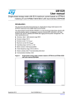
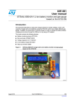
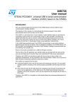
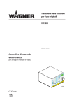
7.1
Schematic and bill of material of STEVAL-IFS014V1
Figure 59. Sheet 1 of schematic of STEVAL-IFS014V1
!-V
Doc ID 16752 Rev 1
-7$*B
-
9
N
5
5
N
5
N
'%*$&.
'%*54
5(6(7
N
N
5
5
3%B-7$*B6:'
3$B-7$*B6:'
3&BQ+267B,17
9
3&BQ5(6(7
5
N
*1'
,&B6&/
9
,&B6'$
3&B7.B5(6(7
3%B7.B7,17
3%B7.B*,17
-
728&+.(<&211
63,B6&.
'
3&BQ5(6(7
9%5'
*1'
6&/.
0,62
026,
8
6B'%*
6,)B6&/.
6,)B0,62
6,)B026,
6,)B/2$'%
37,B(1
37,B'$7$
:$.(
$&7,9,7<
6,)B6&/.
6,)B0,62
6,)B026,
6,)B/2$'%
37,B(1
37,B'$7$
3&BQ:$.(
$&7,9,7<
6'%*
$&7,9,7<
37,B(1
6,)B/2$'%
*1'
63=B6'%*
9
:IG"EECONNECTOR
5
63=B567%
63=%
63,B66(/
+267B,17
567%
+($'(5;
-
=,*%(($&7,9,7</('
9
4OUCHKEYCONNECTOR
9
5
63=B6'%*
37,B'$7$
63=B567%
6,)B6&/.
6,)B026,
6,)B0,62
63,B0,62
-
&21
5
N
3(B06'B&6
5
N
5
57&.
*1'
5 5
N
6'%*
5
QRWXVHG
5
-ICRO3$CARDCONNECTOR
5
N
9
63,B0,62
63,BQ66(/
5
N
5(6(7
3&B6'B&'
9
63,B026,
5
N
9
*4!'CONNECTOR
3%B-7$*
9
63,B6&.
9
63,B026,
3$B-7$*B6:'
3$B-7$*B6:'
3%B-7$*
9
UM0857
Schematics and bill of material
Figure 60. Sheet 2 of schematic of STEVAL-IFS014V1
!-V
47/66
N
5
&
Q)
(UMIDITYSENSOR
9
03(
966
9&&
&
X)
'
&
5(6(7
76/RU:
4
6
8
*1'
3%B-7$*
3$B-7$*B6:'
3$B-7$*B6:'
3$B-7$*B6:'
3%B-7$*B6:'
5(6(7
*1'
86%'0
*1'
86%'3
3$B86%B&175/
3%B%8==
9
9%$7
3%B/2:B%$7
9
5
63,B0,62
3,1&$%/(833(5
-
9
3(B6)B6
5
63,B026,
63,B6&.
9
9&&
8
+,+
*1'
3%B-7$*
3$B-7$*B6:'
3$B-7$*B6:'
3$B-7$*B6:'
3%B-7$*B6:'
5(6(7
*1'
86%'0
*1'
86%'3
3$B86%B&175/
3%B%8==
9
9%$7
3%B/2:B%$7
9
*1'
Doc ID 16752 Rev 1
287
-
3&B79287
5
.
*1'
9
*1'
9
N
5
5
N
*1'
&
Q)
3&B+9287
&21
-
&21
-
)NTERFACECONNECTOR
3,1&$%/(/2:(5
&
Q)
&
Q)
*1'
&
Q)
9
ѵÀ҅ Ѷ ѵ҆ѹ
&
Q)
҇
5
N
3&B/9287
/'5
NN
9
,$2CIRCUIT
67/0:
9287 9
*1'
*1'
8
4EMPERATURESENSOR
3&B7)7B%/
;
<
;
<
N
5
%/B&$7+2'(
,&B6&/
9
&
Q)
9''B,2
1&
1&
6&/
*1'
9
/,6'/+
9
5 5
N N
S)
&
S)
&
S)
&
S)
&
*1'
5
N
5
5
N
9
*1'
5
%/B&$7+2'(
<
;
<
;
9
-
3,17)7&211
5
N
*1'
*1'
3(B0(06B,175
*1'
3(B0(06B,175
9
9
3(B7)7B&6
3(B7)7B56
3(B7)7B:5
4
3(B7)7B5'
675 3&B7)7B5(6(7
3'B7)7B'%
3'B7)7B'%
3'B7)7B'%
3'B7)7B'%
3'B7)7B'%
3'B7)7B'%
3'B7)7B'%
3'B7)7B'%
3'B7)7B'%
3'B7)7B'%
3'B7)7B'%
3'B7)7B'%
3'B7)7B'%
3'B7)7B'%
3'B7)7B'%
3'B7)7B'%
Q)
&
8
*1'
*1'
,17
5(6(59(
,17
4&4DISPLAY
-%-3
*1'
6'$
,&B6'$
9''
&6
5(6(59(
6$
48/66
$ATALOGINGSYSTEM
Schematics and bill of material
UM0857
Figure 61. Sheet 3 of schematic of STEVAL-IFS014V1
!-V
&
X)
/
,1'8&725
9
S)
&
S)
&
S)
&
S)
&
9$
5
95()
26&B287
5
0
26&B,1
3&B26&B287
<
.+]
5
5
%7
%$77(5<
3&B26&B,1
<
0+]
&
Q)
9%$7
9%$7
9
Q)
&
,&B6'$B76&
,&B6&/B76&
-OUNTONLYONERESISTOROUTOF2AND2
N
5
N
5
9
3(B0(06B,175 3(B0(06B,175 3(B6)B6
3(B06'B&6
3&B26&B,1
3&B26&B287
9
26&B,1
26&B287
1567
3&B/9287
3&B79287
3&B+9287
95()
9''$
3$B/$03B/('
3$B$/$50B/(' 3(B6)B6
3%B%8==
3%B/2:B%$7
%227
,&B6'$B76&
,&B6&/B76&
9
3(
3(
3(
3(
3(
9%$7
3&B$17,B7$03(5
3&B26&B,1
3&B26&B287
966B
9''B
26&B,1
26&B287
1567
3&
3&
3&
3&
966$
95()
95()
9''$
3$B:.83
3$
3$
,&B6'$
,&B6&/
9
3%B-7$*
3%B-7$*B6:'
3'B7)7B'%
3'B7)7B'%
3'B7)7B'%
3'B7)7B'%
3'B7)7B'%
3'B7)7B'%
3'B7)7B'%
3'B7)7B'%
3&B7)7B5(6(7
670)9%7
N
5
N
5
9
63,B6&.
63,B0,62
63,B026,
3&B6'B&'
3&B7.B5(6(7
3%B7.B*,17
3%B7.B7,17
%227
3(B,17B76&
3$B-7$*B6:'
3$B-7$*B6:'
9''B
966B
3(
3(
3%
3%
%227
3%
3%
3%
3%
3%
3'
3'
3'
3'
3'
3'
3'
3'
3&
3&
3&
3$
3$
3$
966B
9''B
3$
3$
3$
3$
3&
3&
3%
3%
3%
3(
3(
3(
3(
3(
3(
3(
3(
3(
3%
3%
966B
9''B
3(B7)7B&6
3(B7)7B56
3(B7)7B:5
3(B7)7B5'
,&B6&/
,&B6'$
Doc ID 16752 Rev 1
9
9''B
966B
1&
3$
3$
3$
3$
3$
3$
3&
3&
3&
3&
3'
3'
3'
3'
3'
3'
3'
3'
3%
3%
3%
3%
8
N
5
3&B7)7B%/
3&BQ5(6(7
3&BQ:$.(
3&BQ+267B,17
3'B7)7B'%
3'B7)7B'%
3'B7)7B'%
3'B7)7B'%
3'B7)7B'%
3'B7)7B'%
3'B7)7B'%
3'B7)7B'%
63,B026,
63,B0,62
63,B6&.
63,BQ66(/
3$B-7$*B6:'
86%'3
86%'0
3$B86%B&175/
9
3(B,17B76&
9
9''$
*1'
Q)
6:,7&+
&
N
5
1567
1567
9
&
&
&
&
&
Q) Q) Q) Q) Q)
9
9$
5(6(7
6:
*1'
%227
%227
-ICROCONTROLLERSECTION
UM0857
Schematics and bill of material
Figure 62. Sheet 4 of schematic of STEVAL-IFS014V1
!-V
49/66
Doc ID 16752 Rev 1
6+,(/' 6+,(/'
&
Q)
86%B0,1,
9&&
'
'
,'
*1'
9B86%
5
N
5
0
3(B6)B6
63,B0,62
9
9
)CONFLASH
6+,(/' 6+,(/'
,2
9EXV
,2
5
N
63,B6&.
63,B026,
3$B86%B&175/
86%/&)
,2
*1'
,2
8
0390)73
8
5
N
9
5
&
Q)
9B86%
5
86%'3
86%'0
9
3%B%8==
5
N
N
5
,&B6&/B76&
3(B,17B76&
<
<
;
6&/.
9
6703(
$'DWDBRXW
,17
&
Q)
9
4
675
*1'
9
-
6'$7
,&B6'$B76&
9&&
;
<
<
;
;
,1
9LR
'DWDBLQ
50/66
,1
%8==(5
%
$
%=
8
5
N
,1
*1'
,1
&
Q)
53"SECTION
9
9
5
N
5
5
'
/('
'
/('
3$B$/$50B/('
3$B/$03B/('
"UZZERAND,%${S
4OUCHSCREENCONTROLLER
Schematics and bill of material
UM0857
Figure 63. Sheet 5 of schematic of STEVAL-IFS014V1
!-V
Bill of material of STEVAL-IFS014V1
Doc ID 16752 Rev 1
Ref. des.
Component
description
Package
Manuf.
Manufacturer’s
ordering code /
orderable part number
Supplier
Supplier ordering
code
ST
devices
U1
Battery charger
DFN6
STMicroelectronics
STBC08PMR
STMicroelectronics
STBC08PMR
U2
Step-up converter
TSSOP8
STMicroelectronics
L6920D
STMicroelectronics
L6920D
U3
Voltage regulator (3 V
output)
SOT- 223
STMicroelectronics
LD1117STR
STMicroelectronics
LD1117STR
U4
ZigBee module
contains SN260
device
SMD
STMicroelectronics
SPZB260
STMicroelectronics
SPZB260
U5
Serial Flash (1 MB) used for data logging
SO8W
Numonix
M25PE80-VMW6G
Arrow Electronics
M25PE80-VMW6G
U7
Temperature sensor
(analog)
STLM20W87F
STMicroelectronics
STLM20W87F
U8
MEMS
QFPN-28
STMicroelectronics
LIS331DLH
STMicroelectronics
LIS331DLH
U9
Microcontroller
working as host for all
the devices
connected
LQFP100
STMicroelectronics
STM32F103VBT6
STMicroelectronics
STM32F103VBT6
U10
USB protection
device
SOT-666
STMicroelectronics
USBLC6-2P6
STMicroelectronics
USBLC6-2P6
U11
Serial Flash (16 MB) used for pictures
storage
SO-16
Numonix
M25P128-VMF6TP
Arrow Electronics
M25P128-VMF6P
U12
Reset IC
SO8W
STMicroelectronics
STM1061N29WX6F
STMicroelectronics
STM1061N29WX6F
U13
Touchscreen
controller
QFN-16
STMicroelectronics
STMPE811QTR
STMicroelectronics
STMPE811QTR
D4, D5
Power diode
SMA
STMicroelectronics
STPS1L30A
STMicroelectronics
STPS1L30A
Q3, Q4
NPN transistor
SOT - 23
STMicroelectronics
2STR1215
STMicroelectronics
2STR1215
SOT323-5 STMicroelectronics
Schematics and bill of material
51/66
Category
UM0857
Table 2.
Bill of material of STEVAL-IFS014V1 (continued)
Component
description
Package
Manuf.
Manufacturer’s
ordering code /
orderable part number
Supplier
Supplier ordering
code
Q1
P-channel power
MOSFET
SOT- 223
STMicroelectronics
STN3PF06
STMicroelectronics
STN3PF06
Other
Devices
U6
Humidity sensor
Through
hole
Honeywell
HIH--4003 or HIH-4000
Dishant Impex
HIH--4003 or HIH-4000
Crystal
and
Oscillator
Y1
Crystal 8 MHz
Through
hole
ABRACON
ABL-8.000MHZ-B2
MOUSER
ELECTRONICS
815-ABL-8-B2
Y2
Crystal 32.768 kHz
Through
hole
ABRACON
AB26T-32.768 kHZ
MOUSER
ELECTRONICS
815-AB26T-32.768KHZ
SW2
Tact switch
Through
hole
ALPS
SKHHAPA010
MOUSER
ELECTRONICS
688-SKHHAP
SW1
Slide switches DPDT
on-on (power on/off)
Through
hole
C&K Components
OS202011MA0QN1
MOUSER
ELECTRONICS
611OS202011MA0QN1
BT2
3V Li-Ion coin battery
holder
Through
hole
Renata
HU2032-LF
MOUSER
ELECTRONICS
614-HU2032-LF
BT1
Header for 3.7 V LiIon battery
connection
Through
hole
Any
J2
JTAG connector
20-pin
(pitch 2.54
mm)
3M Electronic
Solutions division
30320-6002HB
MOUSER
ELECTRONICS
517-30320-6002
J7
TFT display
SMD
connector
AMPIRE Co., LTD
AM240320L7TNQWT0
2H
AMPIRE Co., LTD
AM240320L7TNQWT0
2H
J6
Mini USB connector
USB mini
B-type
Mill-Max
Manufacturing
Corp.
897-43-005-00-100001
Digi-Key
ED90341CTND
J4
Micro SD card
connector
Proconn
technology
MSPN09-X0-1000
Global sources
MSPN09-X0-1000
Doc ID 16752 Rev 1
Connector
s and
jumpers
52/66
Schematics and bill of material
Ref. des.
Category
UM0857
Table 2.
Category
Doc ID 16752 Rev 1
LEDs
Bill of material of STEVAL-IFS014V1 (continued)
Component
description
Package
Manuf.
Manufacturer’s
ordering code /
orderable part number
Supplier
Supplier ordering
code
J3
Connector for touch
key daughterboard
Throughhole, 2.54
mm
BergStrip
SAMTEC
TSW-108-23-G-S
Integrated
Electronics
TSW-108-23-G-S
J9
Header for stack
updation of ZigBee
module SPZB260
SMD
SAMTEC
FTSH-105-01-F-DV-K
Integrated
Electronics
FTSH-105-01-F-DV-K
J1
20-pin cable
connector
SMD
SAMTEC
ZF1-20-01-T-WT
Integrated
Electronics
ZF1-20-01-T-WT
J8
20-pin cable
connector
SMD
SAMTEC
FC1-20-02-T-WT
Integrated
Electronics
FC1-20-02-T-WT
D1
Blue LED - ZigBee
activity
Throughhole, 3 mm
round
Kingbright
WP7104QBC/D
MOUSER
ELECTRONICS
604-WP7104QBC/D
D2
Green LED - power
status of the system
Throughhole, 3 mm
round
Kingbright
WP7104GC
MOUSER
ELECTRONICS
604-WP7104GC
D3
Orange LED indication of battery
charging ongoing
Throughhole, 3 mm
round
Kingbright
WP7104NC
MOUSER
ELECTRONICS
604-WP7104NC
D6
Red LED - alarm
signal indicator
Throughhole, 3 mm
round
Kingbright
WP7104SRC/D
MOUSER
ELECTRONICS
604-WP7104SRC/D
D7
Yellow LED - lamp
Throughhole, 3 mm
round
Kingbright
WP7104YC
MOUSER
ELECTRONICS
604-WP7104YC
2 pF
SMD0805
Any
C30, C31
10 pF
SMD0805
Any
C28, C29,
20 pF
SMD0805
Any
Capacitor C36, C37, C38,
s
C39
53/66
Schematics and bill of material
Ref. des.
UM0857
Table 2.
Category
Doc ID 16752 Rev 1
Inductors
Bill of material of STEVAL-IFS014V1 (continued)
Supplier
Supplier ordering
code
Rohm
semiconductor
TCA1A106M8R
Digi-Key
511-1463-1-ND
22 µH (630 MA)
SMD
(6.0 mm x
6.0 mm x
1.2 mm )
(L x W x H)
Taiyo Yuden
NR6012T220M
Digi-Key
587-1708-1-ND
1 µH (reactance 600
at 100 MHz)
SMD0805
MuRata
BLM21B601S
Digi-Key
490-1046-1-ND
0
SMD0805
Any
R51, R52
22 Ω
SMD0805
Any
R47
47 Ω
SMD0805
Any
R11, R58
100 Ω
SMD0805
Any
R1, R2
220 Ω
SMD0805
Any
R25, R54
330 Ω
SMD0805
Any
Component
description
Package
Manuf.
C32
4.7 nF
SMD0805
Any
C23, C24, C25,
C26, C34
10 nF
SMD0805
Any
C33
47 nF
C1,C2,C3,C4,
C5,C6,C7,C8,
C9,C10,C11,
C12,C13,C14,
C15,C16,C17,
C18, C35, C40
100 nF
SMD0805
Any
C21, C22, C27,
Tantalum cap 10 µF
SMD1206
C19,C20
Tantalum cap 47 µF
SMD1206
L1
L2
R29, R30, R31,
Resistors R32, R41, R61,
R65
UM0857
Manufacturer’s
ordering code /
orderable part number
Ref. des.
Schematics and bill of material
54/66
Table 2.
Category
Doc ID 16752 Rev 1
55/66
Manufacturer’s
ordering code /
orderable part number
Supplier
Supplier ordering
code
CUI Inc
CEP-2242
Digi-Key
102-1115-ND
Advanced
Photonix Inc
PDV-P5001
Digi-Key
PDV-P5001-ND
Ref. des.
Component
description
Package
Manuf.
R8, R9, R10
470 Ω
SMD0805
Any
R64, R66
511 Ω
SMD0805
Any
R34,
R43,R44,R45,
R62, R67
1 kΩ
SMD0805
Any
R50, R63
1.5 kΩ
SMD0805
Any
R7
2.7 kΩ
SMD0805
Any
R33, R35, R36,
R37, R38, R39,
R40, R57, R68,
R69
4.7 kΩ
SMD0805
Any
R14,R15, R16,
R17, R18, R19,
R20, R21, R22,
R23, R24,
R26,R28, R55,
R56
10 kΩ
SMD0805
Any
R12
15 kΩ
SMD0805
Any
R46
33 kΩ
SMD0805
Any
R3, R4, R5,
R6, R59, R60
100 kΩ
SMD0805
Any
R13
180 kΩ
SMD0805
Any
R48, R49
1 MΩ
SMD0805
Any
BZ1
Buzzer
AXIAL
LDR 1
Light-dependant
resistor
Throughhole
Schematics and bill of material
Misc.
compone
nts
Bill of material of STEVAL-IFS014V1 (continued)
UM0857
Table 2.
Bill of material of STEVAL-IFS014V1 (continued)
Category
Note:
Ref. des.
Component
description
Package
Manuf.
Manufacturer’s
ordering code /
orderable part number
Supplier
Supplier ordering
code
-
Cable to connect J1
and J8 after breakup
of the board
-
Samtec
FJ-20-D-03.00-4
Integrated
Electronics
FJ-20-D-03.00-4
Casing
OKW
A9052107 and
A952017 and
A9152007
Schurter
Electronics (India)
A9052107 and
A952017 and
A9152007
Doc ID 16752 Rev 1
1
Out of R30 and R31 only one resistor is to be mounted
2
R32 is not to be mounted.
3
Components SW2, BT1, J3, J4 and J9 are not mounted.
Schematics and bill of material
56/66
Table 2.
UM0857
6+'1
9&&
'
'
,'
*1'
5
'
32:(5/('
9
9%$7
9B86%
5
0
9&&
6701:;)
966
287
8
&
Q)
86%B0,1,
6+,(/' 6+,(/'
6+,(/' 6+,(/'
-
&
Q)
5
N
%$7
&+5*
32:(521
352*
9&&
8
67%&305
*1'
%7
9B/L,21
N
5
9%$7
5
'
<(//2:
Doc ID 16752 Rev 1
5
&
X)
4
6713)
5
X+
/
6736/$
'
6736/$
'
&
Q)
Q)
&
5()
)%
/;
8
/'
,1
5
N
5
N
5
N
9%$7
5
N
287
5
N
&
X)
&
X)
&
Q)
3$B/2:%$7
5
N
9
9B%$7
9
0OWERSUPPLY
8
/'675627
6+'1
9B%$7
6+'1
/%
/%
287
&
Q)
9
9
32:(56:,7&+
6:
*1'
*1'
7.2
UM0857
Schematics and bill of material
Schematic and bill of material of STEVAL-IFS015V1
Figure 64. Sheet 1 of schematic of STEVAL-IFS015V1
!-V
57/66
͙ Ǯѱҁҍ
͙ Ǯѱѳ
͙ ǭѳ͚
S)
&
S)
&
S)
&
S)
&
͙ ǮҔѲ
9
5
5
À͚ѲǮǭ
&
X)
/
,1'8&725
%7
%$77(5<
9
¿ǮҔѱѲ
ҏ ǭ҅ Ґ
26&B287
5
0
9%$7
3&B$17,B7$03
3&B26&B,1
3&B26&B287
3'26&B,1
3'26&B287
1567
966$
9''$
3$B:.83
3$
3$
9
670)&7
3%B-7$*B/$03B/('
9
3%B-7$*B$/$50B/('
N
5
&
&
&
Q) Q) Q)
9
3$B%8==
9''$
3$B567B/&'
3$B79287
3$B/9287
3&B$B/&'
26&B,1
26&B287
26&B,1
26&B287
1567
26&B,1
26&B287
<
.+]
26&B,1
<
0+]
&
Q)
9$
͙ ǮҊ ͙ ǭ҅Ҏ
3%B/&'
3%B/&'
*1'
,&B6'$B0(06
,&B6&/B0(06
3%B,175B0(06
3%B-7$*B/$03B/('
3%B-7$*B$/$50B/('
3$B-7$*
3$B-7$*
9''B
966B
3%
3%
%227
3%
3%
3%
3%
3%
3$
3$
3$
3$
3$
3$
3$
3%
3%
3%
3%
3%
966B
9''B
&21
-
4
675
9
9''B
966B
3$
3$
3$
3$
3$
3$
3%
3%
3%
3%
%8==(5
%
$
%=
9
3$B+9287
3$B/&'
3$B/&'
3$B/&'
3$B/&'
3%B(B/&'
3%B,175B0(06
3%B(B/&'
3%B/&'
3%B/&'
Doc ID 16752 Rev 1
8
*1'
9
Q)
&
6:,7&+
6:
3%B-7$*B/$03B/('
3%B-7$*B$/$50B/('
,&B6'$B0(06
,&B6&/B0(06
3$B-7$*
3$B%8==
3$B/2:%$7
3$BQ+267B,17
3$BQ5(6(7
3$BQ:$.(
63,B026,
63,B0,62
63,B6&.
3%BQ66(/
5
9
9
5(6(7
N
5
1567
/('
'
/('
'
N
5
N
9
1567
5
5
9
9
-7$*B
-
5
9
N
5
N
5
N
'%*$&.
'%*54
5(6(7
N
5 N
5
3%B-7$*B$/$50B/('
57&.
3$B-7$*
3$B-7$*
3$B-7$*
3%B-7$*B/$03B/('
9
3$B567B/&'
5
N
5
N
9
%$7-
'
N
5
12702817('
5
'%*$&.
5
N
5
12786('
*4!'CONNECTOR
3%B-7$*B/$03B/('
5(6(7
58/66
9
-ICROCONTROLLERSECTION
Schematics and bill of material
UM0857
Figure 65. Sheet 2 of schematic of STEVAL-IFS015V1
!-V
Doc ID 16752 Rev 1
3%B/&'
3%B/&'
3$B/&'
3$B/&'
3%B(B/&'
5
N
/&'',63/$<
-
9
5
&
Q)
&
X)
3$B567B/&'
3%B(B/&'
3&B$B/&'
3%B/&'
3%B/&'
3$B/&'
3$B/&'
,#$DISPLAY
/&'9
(UMIDITYSENSOR
5
5
N
3$B/9287
/'5
NN
5
&
Q)
҇
/&'9
9
Ѳ҅ Ѷ Ѳ҆ѹ
9&&
8
+,+
287
5
.
63,B6&.
.
5
63,B026,
63,B0,62
9
3%BQ66(/
'
+($'(5;
9%5'
*1'
6&/.
0,62
026,
&
Q)
-
6,)B6&/.
6,)B0,62
6,)B026,
6,)B/2$'%
37,B(1
37,B'$7$
:$.(
$&7,9,7<
6B'%*
63=B567%
63=%
63,B66(/
+267B,17
567%
3$BQ5(6(7
5
6,)B6&/.
6,)B0,62
6,)B026,
6,)B/2$'%
37,B(1
37,B'$7$
3$BQ:$.(
$&7,9,7<
6'%*
$&7,9,7<
37,B(1
6,)B/2$'%
*1'
63=B6'%*
9
:IG"EESENSOR
=,*%(($&7,9,7</('
3$B+9287
3$BQ+267B,17
9
3$BQ5(6(7
5
63=B6'%*
5
6'%*
&
Q)
3$B79287
5
.
&
Q)
,&B6&/B0(06
9
Q)
&
9''B,2
1&
1&
6&/
*1'
9
8
9
5 5
N N
/,6'/+
*1'
*1'
,17
5(6(59(
,17
5 5
N N
*1'
*1'
3%B,175B0(06
*1'
3%B,175B0(06
-%-3
*1'
67/0:
9287 9
*1'
*1'
8
&
Q)
9
4EMPERATURESENSOR
,&B6'$B0(06
-
*1'
6'$
5(6(59(
6$
9''
&6
37,B'$7$
63=B567%
6,)B6&/.
6,)B026,
6,)B0,62
9
,$2CIRCUIT
9
9
*1'
UM0857
Schematics and bill of material
Figure 66. Sheet 3 of schematic of STEVAL-IFS015V1
!-V
59/66
Category
UM0857
Table 3.
Bill of material of STEVAL-IFS015V1
Manuf.
Manufacturer’s
ordering code /
orderable part
number
Supplier
Supplier ordering
code
SOT- 223
STMicroelectronics
LD1117STR
STMicroelectronics
LD1117STR
Step-up converter
TSSOP8
STMicroelectronics
L6920D
STMicroelectronics
L6920D
Battery charger
DFN6
STMicroelectronics
STBC08PMR
STMicroelectronics
STBC08PMR
STM32F103C8T6
STMicroelectronics
STM32F103C8T6
Ref. des.
Component
description
Package
U1
Voltage regulator (3 V
output)
U2
U3
U4
Microcontroller working
as host for all the
LQFP48 (7 X 7) STMicroelectronics
devices connected
Doc ID 16752 Rev 1
U5
MEMS
QFPN-16
STMicroelectronics
LIS331DLH
STMicroelectronics
LIS331DLH
U7
Temperature sensor
(analog)
SOT323-5
STMicroelectronics
STLM20W87F
STMicroelectronics
STLM20W87F
U8
Low-voltage detector
SOT23-3
STMicroelectronics
STM1061N29WX6F
J3
ZigBee module contains
SN260 device
SMD
STMicroelectronics
SPZB260
STMicroelectronics
SPZB260
D1,D2
Power diode
SMA
STMicroelectronics
STPS1L30A
STMicroelectronics
STPS1L30A
Q2
NPN transistor
SOT - 23
STMicroelectronics
2STR1215
STMicroelectronics
2STR1215
Q1
P-channel power
MOSFET
SOT- 223
STMicroelectronics
STN3PF06
STMicroelectronics
STN3PF06
D8
Schottky diode
SMD
STMicroelectronics
BAT54JFILM
STMicroelectronics
BAT54JFILM
Other
devices
U6
Humidity sensor
Through-hole
Honey - Well
HIH--4003 or HIH4000
Dishant Impex
HIH--4003 or HIH4000
Crystal
and
oscillator
Y1
Crystal 8 MHz
Through-hole
ABRACON
ABL-8.000MHZ-B2
MOUSER
ELECTRONICS
815-ABL-8-B2
Y2
Crystal 32.768 kHz
Through-hole
ABRACON
AB26T-32.768KHZ
MOUSER
ELECTRONICS
815-AB26T-32.768
kHZ
ST devices
STMicroelectronics STM1061N29WX6F
Schematics and bill of material
60/66
Category
Doc ID 16752 Rev 1
Connector
s and
jumpers
Bill of material of STEVAL-IFS015V1 (continued)
Supplier
Supplier ordering
code
Through-hole
ALPS
SKHHAPA010
MOUSER
ELECTRONICS
688-SKHHAP
Slide switches DPDT
on-on (power on/off)
Through-hole
C&K Components
OS202011MA0QN1
MOUSER
ELECTRONICS
611OS202011MA0QN1
BT2
3 V Li-Ion coin battery
holder
Through-hole
Renata
HU2032-LF
MOUSER
ELECTRONICS
614-HU2032-LF
BT1
Header for 3.7 V Li-Ion
Battery Connection
Through-hole
Any
J1
Mini USB connector
USB Mini BType
Mill-Max
Manufacturing Corp.
897-43-005-00100001
Digikey
ED90341CTND
J5
Header for stack
updation of ZigBee
module SPZB260
SMD
SAMTEC
FTSH-105-01-F-DV-K
Integerated
Electronics
FTSH-105-01-F-DVK
J2
JTAG connector
20-pin (pitch
2.54 mm)
3M electronic
solutions division
30320-6002HB
MOUSER
ELECTRONICS
517-30320-6002
J4 (please
see the
Note 1 also)
Connector to solder on
the graphical display (
please see Note 2)
Header 16-pin ,
2.54 mm pitch
SAMTEC
TSW-150-23-G-S
Integerated
Electronics
TSW-150-23-G-S
Connector to take lamp
Header 16-pin ,
LED and alarm signal
2.54 mm pitch
out of the PCB
SAMTEC
TSW-150-23-G-S
Integerated
Electronics
TSW-150-23-G-S
Ref. des.
Package
SW2
Tact switch
SW1
J6
LEDs
61/66
D3
Blue LED - ZigBee
activity
Through-hole,
3 mm round
Kingbright
WP7104QBC/D
MOUSER
ELECTRONICS
604-WP7104QBC/D
D4
Green LED - power
status of the system
Through-hole,
3 mm round
Kingbright
WP7104GC
MOUSER
ELECTRONICS
604-WP7104GC
D5
Orange LED - indication
of battery charging
ongoing
Through-hole,
3 mm round
Kingbright
WP7104NC
MOUSER
ELECTRONICS
604-WP7104NC
Schematics and bill of material
Manuf.
Manufacturer’s
ordering code /
orderable part
number
Component
description
UM0857
Table 3.
Category
Bill of material of STEVAL-IFS015V1 (continued)
Supplier
Supplier ordering
code
Through-hole,
3 mm round
Kingbright
WP7104SRC/D
MOUSER
ELECTRONICS
604-WP7104SRC/D
Yellow LED - lamp
Through-hole,
3 mm round
Kingbright
WP7104YC
MOUSER
ELECTRONICS
604-WP7104YC
C25,C26
10 pF
SMD0402
Any
C23,C24
20 pF
SMD0402
Any
C27
4.7 nF
SMD0402
Any
C21,C22
10 nF
SMD0402
Any
C1,C2,C3,
C4,C5,C6,
C7,C8,C9,
C10,C11,
C12,C13,
C14,C15
100 nF
SMD0402
Any
C19,C20
47 µF
SMD0402
Any
C16, C17,
C18
Tantalum cap 10 µF
SMD1206
RΩ semiconductor
TCA1A106M8R
Digi-Key
511-1463-1-ND
L1
22 µH (630 MA)
SMD (6.0 mm
x 6.0 mm X 1.2
mm ) (L X W X
H)
Taiyo Yuden
NR6012T220M
Digi-Key
587-1708-1-ND
L2
1 µH (Reactance 600 at
100 MHz)
SMD0805
Murata
BLM21B601S
Digi-Key
490-1046-1-ND
R27, R28,
R29, R30,
R36, R43
0
SMD0402
Any
R2, R3
100 Ω
SMD0402
Any
R4, R5
220 Ω
SMD0402
Any
Ref. des.
Package
D6
Red LED - alarm signal
indicator
D7
LEDs
Doc ID 16752 Rev 1
Capacitors
Inductors
Resistors
UM0857
Manuf.
Manufacturer’s
ordering code /
orderable part
number
Component
description
Schematics and bill of material
62/66
Table 3.
Category
Doc ID 16752 Rev 1
Resistors
Manufacturer’s
ordering code /
orderable part
number
Supplier
Supplier ordering
code
CUI Inc
CEP-2242
Digi-Key
102-1115-ND
Advanced Photonix
Inc
PDV-P5001
Digi-Key
PDV-P5001-ND
Ref. des.
Component
description
Package
Manuf.
R31, R32
330 Ω
SMD0402
Any
R7, R8
470 Ω
SMD0402
Any
R42, R44
511 Ω
SMD0402
Any
R1, R34,
R35, R40
1 kΩ
SMD0402
Any
R41
1.4 kΩ
SMD0402
Any
R6
2.7 kΩ
SMD0402
Any
R37
3.9 kΩ
SMD0402
Any
R25, R26,
R46, R47
4.7 kΩ
SMD0402
Any
R9,R10,R11
,R12,R13,R
14,R15,R16,
R17, R18,
R19, R20,
R21, R22,
R48,
10 kΩ
SMD0402
Any
R23
15 kΩ
SMD0402
Any
R38
22 kΩ
SMD0402
Any
R39
33 kΩ
SMD0402
Any
R24
180 kΩ
SMD0402
Any
R33, R45
1 MΩ
SMD0402
Any
BZ1
Buzzer
AXIAL
LDR 1
Light-dependant resistor
Through-hole
63/66
Schematics and bill of material
Misc
componen
ts
Bill of material of STEVAL-IFS015V1 (continued)
UM0857
Table 3.
Bill of material of STEVAL-IFS015V1 (continued)
Category
Misc
componen
ts
Doc ID 16752 Rev 1
Note:
Ref. des.
Manuf.
Manufacturer’s
ordering code /
orderable part
number
Supplier
Supplier ordering
code
PCB
TechStar
TS12232C
Shenzhen
Techstar
Electronics
TS12232C
Header for graphical
LCD
Header 16-pin ,
2.54 mm pitch
Samtec
SSQ-108-01-G-D
Integrated
Electronics
SSQ-108-01-G-D
Support for graphical
display
1-pin mail berg
strip
Samtec
TSW-150-17-G-S
Integrated
Electronics
TSW-150-17-G-S
LED spacer
3 mm
Keystone
Electronics
8917
MOUSER
ELECTRONICS
534-8917
LED spacer for LDR
3 mm
Keystone
Electronics
8914
MOUSER
ELECTRONICS
534-8914
Case
OKW
A9051107 and
A952047 and
A9151017
Schurter
Electronics (India)
A9051107 and
A952047 and
A9151017
Component
description
Package
Graphical LCD display
1
Header J4 is the male BergStrip which is cut to size and soldered on the PCB. This is used to connect the PCB with the graphical
display. Please see serial part no. - 58, 59 and 60.
2
This is the female Berg Strip which is soldered on the Graphical Display TS12232C, so that the display can be attached on the PCB
through J4
3
Out of R28 and R29, only one to be mounted.
4
R27 and R39 are not to be mounted.
5
Components SW2, BT1, J5 and J6 are not mounted.
Schematics and bill of material
64/66
Table 3.
UM0857
UM0857
8
Revision history
Revision history
Table 4.
Document revision history
Date
Revision
04-Jan-2010
1
Changes
Initial release
Doc ID 16752 Rev 1
65/66
UM0857
Please Read Carefully:
Information in this document is provided solely in connection with ST products. STMicroelectronics NV and its subsidiaries (“ST”) reserve the
right to make changes, corrections, modifications or improvements, to this document, and the products and services described herein at any
time, without notice.
All ST products are sold pursuant to ST’s terms and conditions of sale.
Purchasers are solely responsible for the choice, selection and use of the ST products and services described herein, and ST assumes no
liability whatsoever relating to the choice, selection or use of the ST products and services described herein.
No license, express or implied, by estoppel or otherwise, to any intellectual property rights is granted under this document. If any part of this
document refers to any third party products or services it shall not be deemed a license grant by ST for the use of such third party products
or services, or any intellectual property contained therein or considered as a warranty covering the use in any manner whatsoever of such
third party products or services or any intellectual property contained therein.
UNLESS OTHERWISE SET FORTH IN ST’S TERMS AND CONDITIONS OF SALE ST DISCLAIMS ANY EXPRESS OR IMPLIED
WARRANTY WITH RESPECT TO THE USE AND/OR SALE OF ST PRODUCTS INCLUDING WITHOUT LIMITATION IMPLIED
WARRANTIES OF MERCHANTABILITY, FITNESS FOR A PARTICULAR PURPOSE (AND THEIR EQUIVALENTS UNDER THE LAWS
OF ANY JURISDICTION), OR INFRINGEMENT OF ANY PATENT, COPYRIGHT OR OTHER INTELLECTUAL PROPERTY RIGHT.
UNLESS EXPRESSLY APPROVED IN WRITING BY AN AUTHORIZED ST REPRESENTATIVE, ST PRODUCTS ARE NOT
RECOMMENDED, AUTHORIZED OR WARRANTED FOR USE IN MILITARY, AIR CRAFT, SPACE, LIFE SAVING, OR LIFE SUSTAINING
APPLICATIONS, NOR IN PRODUCTS OR SYSTEMS WHERE FAILURE OR MALFUNCTION MAY RESULT IN PERSONAL INJURY,
DEATH, OR SEVERE PROPERTY OR ENVIRONMENTAL DAMAGE. ST PRODUCTS WHICH ARE NOT SPECIFIED AS "AUTOMOTIVE
GRADE" MAY ONLY BE USED IN AUTOMOTIVE APPLICATIONS AT USER’S OWN RISK.
Resale of ST products with provisions different from the statements and/or technical features set forth in this document shall immediately void
any warranty granted by ST for the ST product or service described herein and shall not create or extend in any manner whatsoever, any
liability of ST.
ST and the ST logo are trademarks or registered trademarks of ST in various countries.
Information in this document supersedes and replaces all information previously supplied.
The ST logo is a registered trademark of STMicroelectronics. All other names are the property of their respective owners.
© 2010 STMicroelectronics - All rights reserved
STMicroelectronics group of companies
Australia - Belgium - Brazil - Canada - China - Czech Republic - Finland - France - Germany - Hong Kong - India - Israel - Italy - Japan Malaysia - Malta - Morocco - Philippines - Singapore - Spain - Sweden - Switzerland - United Kingdom - United States of America
www.st.com
66/66
Doc ID 16752 Rev 1