1
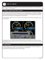
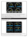
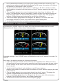
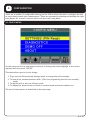
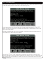
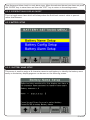
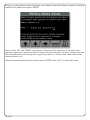
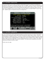
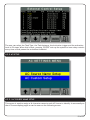
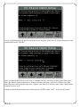
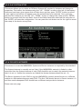
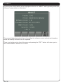
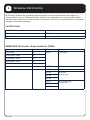
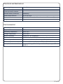
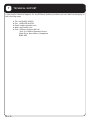
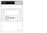
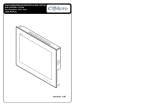
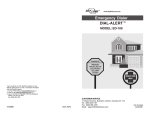
NMEA2000® MULTIFUNCTION DISPLAY
Part Numbers: 3345
USER MANUAL
3345
Revision 1.0
Contents
1 Introduction ...................................................3
1.1 Firmware Revision ........................................ 3
1.2 Product Features ..........................................3
2 Installation .....................................................4
2.1 Unpacking the box.........................................4
2.2 Mounting the unit .........................................4
2.3 Connecting the NMEA2000 Interface Cable ......4
3 Display Screens ...............................................5
3.1 Screen / Keypad Brightness Control .................5
3.2 Tank Display .................................................5
3.3 Battery / DC Source Supply ............................7
3.4 Generator / AC Source Supply .........................8
4 Configuration...................................................9
4.1 Config Menu .................................................9
4.2 PIN Entry .....................................................10
4.2.1 Settings Menu ............................................11
4.2.2 Tank Setup ................................................11
4.2.2.1 Tank Name Setup .....................................12
4.2.2.2 Tank Volume Calibrate .............................13
4.2.2.3 Fluid Units Setup .............................. ......14
4.2.2.4 Tank Alarm Setup ....................................14
1 of 30
4.2.2.5 Percent Only Display ...............................15
4.2.3 Battery Setup ............................................15
4.2.3.1 Battery Name Setup .................................15
4.2.3.2 Battery Config Setup ................................17
4.2.3.3 Battery Alarm Setup ................................17
4.2.4 External Control Setup ...............................18
4.2.5 AC Setup ...................................................19
4.2.5.1 AC Source Name Setup .............................19
4.2.5.2 AC Custom Setup .....................................21
4.2.6 Sys & Dev Instances ....................................21
4.2.7 Config PIN Setup ........................................22
4.3 Com Viewer .................................................23
4.4 Demo On/Off Toggle ......................................23
4.5 About ..........................................................24
5 Maintenance ...................................................25
6 Technical Specification .................................... 26
7 Technical Support ........................................... 28
8 Warranty ........................................................29
9 Troubleshooting/FAQ ....................................... 30
2 of 30
1
INTRODUCTION
The Offshore System’s NMEA2000® 3345 MultiFunction Display is designed to monitor and
display information about the vessel’s tanks, DC supplies such as battery banks, Wind
Generators or Photovoltaic panels and AC Supplies such as generators, shore power or AC
busses.
This unit is designed to operate in a protected marine environment such as at the helm, chart
table or an engine room. It is very important that it is installed and set up correctly according
to this manual. Please read and follow the installation and setup instructions carefully to
achieve the best results.
The information in this manual corresponds to firmware v3.0
1.2 PRODUCT FEATURES
The NMEA2000® 3345 MultiFunction Display has the following features:
●
●
●
●
●
●
Full Colour Sunlight Readable QVGA Display
Pages displaying Tank, DC and AC source information
User Selectable high and low level alarm limits
User Selectable Display Units
PIN protected setup and configuration
NMEA2000 Interface
3 of 30
2
INSTALLATION
2.1 UNPACKING THE BOX x
You should find the following items in the 3345 shipping box:
1 x 3345 NMEA2000® 3345 MultiFunction Display
1 x 3345 NMEA2000® Interface Cable
1 x Bag containing 4 mounting studs and thumbwheel nuts
1 x 3345 User Manual (This document)
2.2 MOUNTING THE UNIT
The unit should be mounted to a flat surface by the 4 mounting studs and thumbwheel nuts.
Use the following unit drawing to identify the positioning of the central clearance hole and the
4 mounting stud locations.
PRIMARY CONNECTOR
MATES WITH DT04-12PA
69.8 mm
69.8 mm
84.8 mm
SECONDARY CONNECTOR
MATES WITH DT04-12PB
51.3 mm
2.3 CONNECTING THE NMEA2000 INTERFACE CABLE
The NMEA2000 interface cable rectangular plug should be plugged into the rear of the unit
taking care to observe the orientation pips on the plug match the corresponding recesses on
the unit’s socket. The other end of the cable should be connected to a nearby NMEA2000 Tee
connector (part number 3802). The male end of the cable should be inserted into the female
Tee connection noting the position of the keyway in the plug and the socket. Ensure that the
locking ring is securely tightened so that the connection remains waterproof and sound.
4 of 30
3
DISPLAY SCREENS
When the unit powers on it displays the initial product identity screen for a few seconds and
then displays the Tank Display.
3.1 SCREEN / KEYPAD BRIGHTNESS CONTROL
The unit has five tactile buttons along its lower face and pressing any of the first four buttons
will bring up the button bar which identifies the current button function. Pressing the required
button will then execute the function chosen and the button bar will disappear a few seconds
later leaving the whole screen displaying the required data.
The fifth button allows the user to vary the screen brightness and keyboard illumination which
is shown below.
Pressing the first two buttons varies the screen brightness and the next two buttons vary the
key backlights. When the desired levels have been set press the fifth button to clear the display
brightness control.
3.2 TANK DISPLAY
The first display screen is Page 0 of the tank levels / volumes display and this can always be
selected by pressing the first or most left hand button on the unit.
An example of this display is shown on the next page.
5 of 30
Here we can see that the Tank Display screen is split into 4 quadrants so the user can monitor
4 tanks at once. The centre of the screen at the junction of the four quadrants displays the
Quadrant Page Number which in the above case is Page 0. The display has eight different pages
available which are selected by repeatedly pressing the “TANK” button which will progressively
step through each display page. This allows the user to display up to eight pages each of four
tanks to a total of thirty two tanks.
Each quadrant of the above display contains the following information:
1. In the top centre of the quadrant is the user assignable tank name. When the unit is delivered each tank type has a generic tank type name that can be set to any name the user wishes to help identify the tank. See section 4.2.3 later in this manual for information on how to do this.
2. At the top left hand side of the quadrant is the Tank Number or Instance which needs to correspond with the number set on the tank sender Address or Instance switch.
3. At the top right hand side of the quadrant (not shown above) there may be a small alarm bell symbol which indicates that this tank level is outside it’s alarm level limits and the alarm has been notified and acknowledged by the user. See the section on Tank Level Alarms in section 4.2.6
4. In the centre of the quadrant is a gauge showing the tank level / volume per
centage and a pictogram of the tank type.
5. In the lower part of the quadrant is a digital display panel. This panel will show the tank level as a percentage, ie 45%, if the total tank volume is not being trans
mitted by the sender. If the sender is transmitting the total tank volume as well as the tank level then the digital display panel will show the remaining fluid volume in either Litres, US Gallons or Imperial Gallons as chosen by the user configuration in section 4.2.2 below.
6. The gauge arc will display partially in red (not shown) if either the low or high level alarm has been set to a suitable value and the alarm has been enabled. See section 4.2.6 later in this manual for information on how to do this.
The user can select which tanks are displayed on each quadrant of each Quadrant Page by
pressing the “TANK” button to bring up the button bar then pressing the “RIGHT ARROW”
button which will alter the buttons to allow each quadrant to be changed.
6 of 30
Pressing the first button the top left hand quadrant will change to display each of the different
tank sender levels being received and then a blank page in case the user does not wish to
display any tank in a given quadrant. Then by pressing the “BACK ARROW” button that selection
will be remembered and the display will revert to the normal tank display.
This can be repeated for each quadrant on each Quadrant Page giving the user the opportunity
to tailor the tank displays exactly as they wish.
3.3 BATTERY / DC SOURCE SUPPLY
By pressing the “BATT” button the display will show information about the first two battery or
DC sources as shown below.
Repeated pressing of the “BATT” button will display the next two batteries or DC sources to a
total of 16 sources. Each side of the display contains the following information:
1. In the top centre of each side is the Battery or DC Source user assignable name. When the 7 of 30
unit is delivered each battery or DC source has a generic name that can be set to any name the user wishes to help identify the Battery or DC source. See section 4.2.4 later in this manual for information on how to do this.
2. At the top left hand side of each side there is a Battery or DC Source Instance number which needs to correspond with the Instance of the DC Monitor supplying the data to the network.
3. The top display gauge is the current charging or being drawn from the battery / DC source. This gauge scale has our “Autoranging” feature so that if the current exceeds 60 amps the gauge scales will automatically autorange to a higher scale. This gauge also includes a digital display panel showing the current flow numerically.
4. The second display gauge shows the voltage of the battery or DC source, also with autoranging between 12 and 24 volt systems and a digital display panel.
5. At the bottom of each side is a battery temperature gauge.
3.4 GENERATOR / AC SOURCE SUPPLY
By pressing the “ACPWR” button the display will show information about the first two AC
Generators or AC Busses or Shore Power as shown below.
Repeated pressing of the “ACPWR” button will display the next two AC sources to a total of 16
sources.
Each side of the display contains the following information:
1. In the top centre of each side is the AC Source user assignable name. When the unit is delivered each AC source has a generic name that can be set to any name the user wishes to help identify the AC source. See section 4.2.5 later in this manual for information on how to do this.
2. At the top left hand side of each side there is an AC Source Instance number which needs to correspond with the Instance of the AC Monitor supplying the data to the network.
3. The top display gauge is the current being drawn from the AC source. This gauge also includes a digital display panel showing the current flow numerically.
4. The second display gauge shows the voltage of the AC source, also with autoranging between 110 and 240 volt systems, and a digital display panel.
5. At the bottom of each side is an AC Source frequency gauge.
8 of 30
4
CONFIGURATION
There are a number of configurable settings on the 3345 to allow the user to configure the unit
to most closely match their requirements. These are accessed by pressing and holding the right
hand button for at least 5 seconds which will start the Config Menu.
4.1 CONFIG MENU
On this menu use the up and down arrow keys to change the yellow highlight to the action
required and then press “ENTER”
This menu allows you to do four things:
1. To go into the PIN protected settings menu to change the unit’s settings.
2. To look at the communications traffic. (This is an engineering function not normally used).
3. To flip the unit in and out of Demo mode.
4. To display the about screen to check on version levels and serial numbers etc.
The use of these options is described on the next page.
9 of 30
4.2 PIN ENTRY
By moving the yellow highlight to “SETTINGS (PIN Reqd)” and pressing enter the display will
show the “CONFIG PIN ENTRY” screen to allow the user to enter a security PIN to access the
configuration screens. This is designed to ensure that only authorised persons can make changes
in this area.
By using the Up and Down and Right arrow buttons the user selected PIN can be entered and
the “ENTER” key will go to the “SETTINGS MENU” if the PIN is correct. If the PIN is not correct
the user is offered the choice to re-enter the PIN or exit back to the “CONFIG MENU” detailed
in 3.1 above.
The system is shipped with a PIN of 0000 and this can be reset to the user’s choice from the
“SETTINGS MENU” “CONFIG PIN SETUP”.
10 of 30
4.2.1 SETTINGS MENU
The “SETTINGS MENU” offers multiple options as shown below
Note the small arrow on the left hand screen indicates that there are more options than can
be shown on one page. All these options and the ones not shown are accessed by moving the
yellow highlighter to the chosen option and then pressing “ENTER”
4.2.2 TANK SETUP
11 of 30
4.2.2.1 TANK NAME SETUP
This screen is used to assign a 16 character name to each tank to identify the tanks more easily
on the tank display pages as can be seen on the following screen.
Firstly the user must select the tank type that is being named by pressing the “TANK TYPE”
button. This will cycle around all the available tank types and the display must be left on the
type of tank to be named.
Secondly, by pressing the “UP” arrow and “DOWN” arrow buttons select the tank instance or
tank number to be named then press “ENTER”.
Next use the “UP” and “DOWN” arrow keys to change the first character of the name then
press the right key to move to be able to change the next character and so on. Please note that
the characters will cycle through A to Z upper case then a to z lower case, then a blank then
numbers from 0 to 9.
12 of 30
4.2.2.2 TANK VOLUME CALIBRATE
This screen is used to set the volume calibration table inside an Offshore System’s 3271 or 3281
Tank Level Sender.
The first screen allows the user to choose the tank type and tank instance of the sender to be
calibrated.
When these have been chosen press “ENTER” to go to the next screen.
The user then enters the volume of fluid at each desired level starting at the lowest chosen
point in as many or as few steps to 100%.
Note that this screen is re-presented at each step until the final level of 100% is entered. When
this happens the unit calculates all the intermediate levels and stores that information in the
chosen sender.
13 of 30
4.2.2.3 FLUID UNITS SETUP
This screen is used to choose between displaying the Fluid Units in Litres, US Gallons or
Imperial Gallons as can be seen by the following screen.
The user can change the units by using the “UP” and “DOWN” arrows and pressing “ENTER” to
select their units of choice. Pressing “EXIT” will return to the “SETTINGS MENU”
4.2.2.4 TANK ALARM SETUP
This screen is used to set the Tank Level Alarm settings for each tank.
The user can select both low and high level alarms for each tank and the alarm level for each
type of alarm.
By pressing the “UP” and “DOWN” arrows the value in the highlighted line will change.
By pressing the “RIGHT” arrow the selector will highlight the Tank Type, Tank Instance, Alarm
14 of 30
Type Status and Alarm level for each alarm type. When the selected alarms have been set press
the “ENTER” key to store them and then the “EXIT” key to return to the settings menu.
4.2.2.5 PERCENT ONLY DISPLAY ON/OFF
This is a toggle menu item which will always show the fluid level numeric value in percent
rather than amount.
4.2.3 BATTERY SETUP
4.2.3.1 BATTERY NAME SETUP
This screen is used to assign a 16 character name to each battery to identify the battery more
easily on the battery display pages as can be seen on the following screen.
15 of 30
Firstly, by pressing the up arrow and down arrow buttons select the battery instance or battery
number to be named then press “ENTER”.
Next use the “UP” and “DOWN” arrow keys to change the first character of the name then
press the right key to move to be able to change the next character and so on. Please note that
the characters will cycle through A to Z upper case then a to z lower case, then a blank then
numbers from 0 to 9.
When the desired name has been written press “ENTER” then “EXIT” to store that name.
16 of 30
4.2.3.2 BATTERY CONFIG SETUP
This screen allows you to select an Offshore Systems DC monitor by instance and change its
properties. First select the instance using the “UP” & “DOWN” arrows on the left (if the battery
instances have been given names this will also show up) then press enter to select. A new right
arrow button will appear once the instance has been selected. To change the values you use
the “UP” & “DOWN” arrows and to proceed to the next field you use the “RIGHT” arrow. Press
the ‘”ENTER” button at anytime to save the configuration.
4.2.3.3 BATTERY ALARM SETUP
To set an alarm firstly select the instance using the up/down buttons on the left (if the battery
instances have been given names this will also show up) then press enter to select. The first
field enables or disables the alarm. The next two fields are low/high voltage alarm values. When
the 3345 Multi function display detects a voltage under the low voltage value or higher than the
high voltage an alarm is displayed. The last temperature field will show an alarm if the display
detects a temperature higher than the set threshold. The setup can be cancelled at any time
using the exit button on the far right.
Please see next page.
17 of 30
4.2.4 EXTERNAL CONTROL SETUP
This screen is used to set up the conditions to operate the 3478 Relay Output Module so that it
can control external alarms, external pumps and other relay controlled actions.
Firstly the user needs to select the Device Instance of the 3478 by using the following screen.
When the Device Instance has been chosen pressing “ENTER” will go to the next screen to allow
choice of the actions to operate each of the eight relays in the 3478 unit.
18 of 30
The user can select the Tank Type, the Tank Instance, the Activation trigger and the activation
level in 5% steps. When this is done, pressing “ENTER” sets up the system to issue relay controls
every time a level passes the activation threshold.
4.2.5 AC SETUP
4.2.5.1 AC SOURCE NAME SETUP
This screen is used to assign a 16 character name to each AC Source to identify it more easily on
the AC Source display pages as can be seen on the following screen.
19 of 30
Firstly, by pressing the up arrow and down arrow buttons select the AC Source instance to be
named then press “ENTER”.
Next use the Up and down arrow keys to change the first character of the name then press
the right key to move to be able to change the next character and so on. Please note that
the characters will cycle through A to Z upper case then a to z lower case, then a blank then
numbers from 0 to 9.
When the desired name has been written press “ENTER” then “EXIT” to store that name.
20 of 30
4.2.5.2 AC CUSTOM SETUP
This screen allows you to select an Offshore Systems AC monitor by instance and change its
properties. First select the instance using the “UP” “DOWN” arrows on the left (if the battery
instances have been given names this will also show up) then press “ENTER” button to select.
A new right arrow button will appear once the instance has been selected. Once you have
selected the instance you use the “UP” “DOWN” arrows to change the value and the ‘ENTER’
button to proceed into the next field. Once all the fields have been selected the last press of
the ‘ENTER’ will save the configuration. You can press the exit button on the far right to cancel
the setup of the device at any time.
4.2.6 SYS & DEV INSTANCES
This screen is to set the NMEA2000® System and Device Instances as required by the standard.
The System Instance is normally set on 0 but if the NMEA2000® network is linked to other
networks then the System Instance of each 3345 should be set to match the network instance
that it is set to. Unless the networks are linked the System Instance should be set = 0;
The Device Instance of each 3345 on a given NMEA2000® network should be set to a different
number to differentiate between each 3345. The first 3345 should be set to Device Instance = 0
and then each subsequent 3345 should have a different unique device instance.
Please see next page.
21 of 30
The user should use the “UP” and “DOWN” arrows to change the value of the Instance that is
underlined and then use the “RIGHT” arrow to select the other Instance.
When the Instance values are correct press “ENTER” to store them and “EXIT” to return to the
Settings Menu.
4.2.7 CONFIG PIN SETUP
This screen is used to change the Configuration PIN to a new number if required.
The user can use the “UP” and “DOWN” arrows to change the value of the underlined PIN
number and then use the “RIGHT” arrow to choose the next number to change.
When the desired PIN number has been chosen pressing the “ENTER” key will store it and then
pressing the “EXIT” key will return to the settings menu.
22 of 30
4.3 COM VIEWER
By moving the yellow highlight to “ DIAGNOSTICS” and then to “COM VIEWER” and pressing
“ENTER” the unit will display the communications traffic arriving to the device. This is shown
below.
This is an engineering diagnostic screen and not normally used. Press “EXIT” to return to the
“CONFIG MENU” detailed in 3.1 above.
4.4 DEMO ON/OFF TOGGLE
By moving the yellow highlight to the “DEMO” position and pressing the enter key, demo mode
can be selected. During demo mode the unit produces its own demo signals to demonstrate the
displays. Under normal use the “DEMO” mode should be off.
Press “EXIT” to return to the normal display screens.
23 of 30
4.5 ABOUT
By moving the CONFIG MENU yellow highlighted selection to “ABOUT” and by pressing enter you
will see a screen similar to that below.
This screen displays data about the unit including the software version and unit serial number
which will identify the exact unit if requested.
There is no further action from this screen and pressing the “EXIT” button will return you to
the “CONFIG MENU” detailed in 3.1 above.
24 of 30
5
MAINTENANCE
● Clean the unit with a soft cloth.
● Do not use chemical cleaners as they may remove paint or markings or may corrode the enclosure or seals.
● Ensure that the unit is mounted securely and cannot be moved relative to the mounting
surface. If the unit is loose, tighten the mounting screws.
● Check the security of the cables connected to the NMEA 2000 connector, tighten if necessary.
25 of 30
6
TECHNICAL SPECIFICATION
As Offshore Systems are constantly improving their products specifications are subject to
change without notice. Offshore System’s products are designed to be accurate and reliable
however they should only be used as aids to navigation and not as a replacement for traditional
navigation aids and techniques.
Certifications
NMEA2000
Level B
Maritime Nav and RadioComm Equipment
IEC60945
CE and FCC
Electromagnetic Compatibility
NMEA2000 Parameter Group Numbers (PGNs)
Source
Max No
PGN
Description
Fuel Tanks
16
127505
Fluid Level
Fresh Water Tanks
16
Grey Water Tanks
16
Black Water Tanks
16
Oil Tanks
16
DC Sources/Battery Banks
16
127507
Battery Status
AC Monitors
16
127508
DC Detailed Status
127744
AC Power
Phases A,B,C
127745
127746
127747
127748
127749
26 of 30
AC Voltage/Freq
Phases A,B,C
Electrical and Mechanical
Operating Voltage
10 to 32 Volts
Power Consumption
250mA
Load Equivalence Number
5
Reverse Battery Protection
Indefinitely
Load Dump Protection
Yes to SAE J1113
Size
95mm (W) x 95mm (H) x 23mm forward and 23mm rear (D)
Weight
160gm
Environmental
IEC 60954 Classification
Protected
Degree of Protection
IP67
Operating Temperature
-20 to +70°C
Storage Temperature
-30 to +80°C
Relative Humidity
93%RH @40° per IEC60945-8.2
Vibration
2-13.2Hz @ ±1mm, 13.2-100Hz @ 7m/s2 per IEC 60945-8.7
Electromagnetic Emission
Conducted and Radiated Emission per IEC 60945-9
Electromagnetic Immunity
Conducted, Radiated, Supply, and ESD per IEC 60945-10
Safety Precautions
Dangerous Voltage, Electromagnetic Radio Frequency per IEC
60945-12
27 of 30
7
TECHNICAL SUPPORT
If you require technical support for any Offshore Systems products you can reach us using any of
the following ways:
28 of 30
●
●
●
●
●
Tel: +44(0)1425 610022
Fax: +44(0)1425 614794
Email: [email protected]
Web: www.osukl.com
Post: Offshore Systems UK Ltd
Unit 10-11 Milton Business Centre
Wick Drive, New Milton, Hampshire
BH25 6RH
8
WARRANTY
Offshore Systems warrants this product to be free from defects in materials and workmanship for one
year from the date of original purchase. If within the applicable period any such products shall be
proved to Offshore Systemssatisfaction to fail to meet the
above limited warranty, such products shall be repaired or replaced at Offshore Systems option.
Purchaser’s exclusive remedy and Offshore Systems sole obligation hereunder, provided product is
returned pursuant to the return requirements below, shall be limited to the repair or replacement,
at Offshore Systems option, of any product not meeting the above limited warranty and which is
returned to Offshore Systems; or if Offshore Systems is unable to deliver a replacement that is free
from defects in materials or workmanship, Purchaser’s payment for such product will be refunded.
Offshore Systems assumes no liability whatsoever for expenses of removing any defective product
or part, or for installing the repaired product or part or a replacement therefore or for any loss or
damage to equipment in connection with which Offshore Systems products or parts shall be used.
The foregoing warranties shall not apply with respect to products subjected to negligence, misuse,
misapplication, accident, damages by circumstances beyond Offshore Systems control, to improper
installation, operation, maintenance, or storage, or to other than normal use or service.
THE FOREGOING WARRANTIES ARE EXPRESSLY IN LIEU OF AND EXCLUDES ALL OTHER EXPRESS
OR IMPLIED WARRANTIES, INCLUDING BUT NOT LIMITED TO THE IMPLIED WARRANTIES OF
MERCHANTABILITY AND OF FITNESS FOR A PARTICULAR PURPOSE.
Statements made by any person, including representatives of Offshore Systems, which are
inconsistent or in conflict with the terms of this Limited Warranty, shall not be binding upon Offshore
Systems unless reduced to writing and approved by an officer of Offshore Systems.
IN NO CASE WILL OFFSHORE SYSTEMS BE LIABLE FOR INCIDENTAL OR CONSEQUENTIAL DAMAGES,
DAMAGES FOR LOSS OF USE, LOSS OF ANTICIPATED PROFITS OR SAVINGS, OR ANY OTHER LOSS
INCURRED BECAUSE OF INTERRUPTION OF SERVICE. IN NO EVENT SHALL OFFSHORE SYSTEMS
AGGREGATE LIABILITY EXCEED THE PURCHASE PRICE OF THE PRODUCT(S) INVOLVED. OFFSHORE
SYSTEMS SHALL NOT BE SUBJECT TO ANY OTHER OBLIGATIONS OR LIABILITIES, WHETHER ARISING
OUT OF BREACH OF CONTRACT OR WARRANTY, TORT (INCLUDING NEGLIGENCE), OR OTHER THEORIES
OF LAW WITH RESPECT TO PRODUCTS SOLD OR SERVICES RENDERED BY OFFSHORE SYSTEMS, OR ANY
UNDERTAKINGS, ACTS OR OMISSIONS RELATING THERETO.
Offshore Systems does not warrant that the functions contained in any software programs or products
will meet purchaser’s requirements or that the operation of the software programs or products will
be uninterrupted or error free. Purchaser assumes responsibility for the selection of the software
programs or products to achieve the intended results, and for the installation, use and results
obtained from said programs or products. No specifications, samples, descriptions, or illustrations
provided by Offshore Systems to Purchaser, whether directly, in trade literature, brochures or other
documentation shall be construed as warranties of any kind, and any failure to conform to such
specifications, samples, descriptions, or illustrations shall not constitute any breach of Offshore
Systems limited warranty.
Warranty Return Proceduree
To apply for warranty claims, contact Offshore Systems or one of its dealers to describe the problem
and determine the appropriate course of action. If a return is necessary, place the product in its
original packaging together with proof of purchase and send to an Authorized Offshore Systems
Service Location. You are responsible for all shipping and insurance charges. Offshore Systems will
return the replaced or repaired product with all shipping and handling prepaid except for requests
requiring expedited shipping (i.e. overnight shipments). Failure to follow this warranty return
procedure could result in the product’s warranty becoming null and void.
Offshore Systems reserves the right to modify or replace, at its sole discretion, without prior
notification, the warranty listed above.
29 of 30
9
TROUBLESHOOTING/FAQ
Please note that below are some FAQ/Troubleshoot Questions. If none of these help or apply,
then please don’t hesitate to contact Technical Support.
Quadrant(s) are showing as empty spaces after
changing tanks.
When adjusting tanks in quadrant spaces, if an
unpainted blank gauge is applied to a quadrant,
it will show as a blank space.
I can’t remember my PIN number for the System
Config Menu.
Contact Technical Support and ask for the
Master PIN, when you are in to the System
Config Menu, you can reset the PIN.
Tank/ Battery Names have disappeared when
editing them in the Name Setup.
Exit the setup without saving the name. When
you re-enter the name should reset to the
Default Name.
It isn’t displaying the correct Fuel/Water level.
-Check the sender instance matches with the
tank instance being monitored.
- Check the sender has been properly
calibrated. If not re-calibrate with a magnet as
shown on Fuel Sender Installation Instructions
Not all of the senders are available to paint in
the quadrants.
To save time scrolling through every tank
sender aswell as its 16 instances, it will only
scan through the senders which it has seen
transmitting onto the NMEA2000 Network.
What is the difference between the System
Instance and Device Instance?
The Device Instance is the 3345’s instance
whereas the System Instance is the NMEA
Network’s instance. These should both match
for the 3345 to work.
Is the 3345 Waterproof?
The 3345 is not completely waterproof, it is
water resistant to IP67 this means- it’s
protected from dust and Protected against the
effects of immersion in water to depth between
15 cm and 1 meter.
What is the small alarm symbol in the tank
quadrant?
This lets you know when your tank level is too
high/low. This is fully customisable in the Tank
Alarm Setup page in the Config Settings.
Offshore Systems (UK) Ltd
Unit 10 -11 Milton Business Centre, Wick Drive,
New Milton, Hampshire, BH25 6RH, United Kingdom
Tel: +44(0)1425 610022
Email: [email protected]
Fax: +44(0)1425 614794
Web: www.osukl.com
Copyright © 2013 Offshore Systems (UK) Ltd. All rights reserved.Our policy is one of continuous product improvement so product
specifications are subject to change without notice. Offshore Systems products are designed to be accurate and reliable. However,
they should be used only as aids to vessel monitoring, and not as a replacement for traditional navigation and vessel monitoring
techniques. NMEA2000® is a registered trademark of the National Marine Electronics Association.
30 of 30
6
OFFSHORE SYSTEMS PRODUCT MAP