1
Critical Assessment Document: V-IR-Bull’s Convolution Reverberation
1
Critical Assessment Document
V-IR-Bull: Convolution Reverberation
Team Members: Dain Marvel, Taylor Morris, Colt Hartstein
Advisors: Dr. Paris Wiley, Dr. Ravi Sankar
Sponsor: Morrisound Recording Studios
Abstract— V-IR-Bull currently offers two Convolution
Reverberation systems; one specific to audio professionals, and
one for the consumer audiophile. These systems work to
artificially recreate the reverberant characteristics of the
acoustically desirable spaces of the users choosing in three stages
of listening or recording applications: Reverberant Capture,
Audio Convolution, and Music Playback.
SOUND
INTRODUCTION
IS EVERYTHING. It moves the air we breathe. It
shapes the rooms in which we thrive, lending us clues as
to their vastness – to quite literally the fabric of their
existence. Sound is how we communicate not just laughter and
song, but with the very walls that surround us. V-IR-Bull's
Convolution Reverb gives you the freedom of sound in any
space, allowing you to take the fingerprint of your favorite
rooms with you for music playback or recording applications,
wherever you may wander.
AUDIO HARDWARE
Professional System
Each audio engineer has their personal preference in gear
choices and the professional system is designed to easily
integrate the audio professional’s arsenal of professional-grade
gear used in recording and mixing applications. The following
describes the characteristics and I/O requirements to
successfully interface one’s own gear with our system.
1. Studio-Grade Equipment Requirements
The microphone used in capture is of particular
importance; it must be sensitive enough to capture all
auditory nuances whilst maintaining near-perfect flatband
pick up characteristics. We strongly recommend using a
DPA4011 condenser microphone, as it was originally
designed for use in laboratory setting and consequently
exhibits a near-perfect flatband pickup characteristic, with
3dB corners at 20-20kHz (the audible range) [1]. We also
selected an ElectroVoice ZLX-12P 1000W self-powered
speaker for our capture stage, for its ability to reproduce the
audio signal sent to it with relatively equivalent energy output
across 20-20kHz. And, finally a mixer that hosts, at
minimum, 2 channels with gain control, each featuring an
option to host phantom power to the mic-in connections as
well as read line-in and send line-out to each channel, an alt
line-out L/R, and a main mic-out with independent gain
control to send to the PA speaker. We utilized a Mackie
1202VLZ.
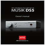
2. Prototype Configuration
This prototype is featured in its current stage in Figure 1,
and is nearing completion proportionate to funding available.
The front panel features cut outs for the pushbutton and LCD
control networks, and laser etched labeling. Also prepared for
installation are slots for USB and HDMI access into the
Raspberry Pi network. The 3.5mm holes for audio inputs and
output connectors are also drilled and labeled.
The rear panel features placement for a power converter and
master power switch. Also ready to install is a cutout for the
fan with independent power control for deactivation during
capture.
Consumer System
The consumer system is geared primarily toward playback,
allowing the user to listen to their own music within our builtin presets (pre-captured impulse responses ready to use in
convolution), or even capture their own rooms.
1. Consumer-Grade Equipment
A cubby slot has been built into the box for the integration
of an AKG 120 Perception condenser microphone, or a
condenser mic of equivalent flatband pick up and size. Due to
their capsule design, condenser mics feature consistency in
energy capture across audible frequencies, using the
movement of a diaphragm in response to a sound pressure
waves to fluctuate the capacitance between it and a back plate,
generating an analog electrical representation of the
frequencies 'heard' in real time. However, condenser mics
need 48v of "phantom" power to be applied across the
capacitor terminals to properly operate, and so a small 48v
power supply is incorporated into this unit; an ST-MPA48
Dual Microphone Phantom Adaptor [2], which supplies this
potential difference.
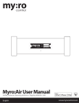
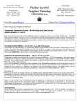
The output of the microphone is pulled from the ST-MPA48
and fed into an LM4562 Differential Input Microphone
Preamplifier (see Figures 2 and 3), which we have bread
boarded, etched and soldered. The resistor ladders in this
Preamp design provide a gain of 91.09v/v, or 39.2dB, which is
sufficiently close to the standard 40dB preamp gain used
before mixing. To power the op amp chips used, a 15v Power
supply has been also integrated into this design.
Critical Assessment Document: V-IR-Bull’s Convolution Reverberation
For capture and playback purposes, a Bose Speaker is
housed into the front panel of this system, and offers easy
access to control the gain of the output signal. This is
especially essential in the capture stage, as between 85dB and
90dB must be present at the microphone during capture (as
determined by Lucas Film, Ltd. and the industry standards in
evaluating speaker performance). A cubby for SPL Meter has
also been incorporated into the prototype to be clipped to the
mic stand for monitoring the sound pressure level present at
the microphone.
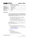
2. Prototype Configuration
This prototype is featured in its current stage in Figure 4,
and is nearing completion proportionate to funding available.
The front panel features cutouts for the pushbutton and LCD
control networks, and laser etched labeling. The Bose speaker
is situated into this panel as well, with its gain knob readily
accessible. The holes 3.5mm audio output connectors are also
drilled and labeled.
The rear panel features placement for power converter and
master power switch. Also ready to install is a cutout for the
fan, with independent power control for deactivation during
capture. Also prepared for install are slots for USB and HDMI
access into the Raspberry Pi network.
Also incorporated into the prototype is an XLR Female
throughput connector on a side panel (which is connected to
the rails on the phantom power box, supplying 48v across the
capacitive plates in the condenser mic, and outputs zero bias to
the LM4562 Mic preamplifier) as well as the cubbies for the
placement of the microphone and SPL meter on the top panel.
CONTROLS HARDWARE AND FUNCTIONS
Wolfson Network Sub-System
1. Wolfson Audio Card
This card (see Figure 5) hosts high fidelity I/O functions to
and from both analog and digital outputs and inputs. This is
due to the ADAC (analog to digital conversions and vice
versa) function it performs, which is easily programmed for
recording and playback in a variety of resolution bit sizes and
sampling frequencies. For this stage of prototyping, we have
programmed the card to run I/O at CD fidelity: 16bit
resolution and 44.1kHz sampling rate. The architecture of the
main audio functions can be seen in Figure 6, supplied by the
Wolfson user manual [3], featuring the signal flow and pin
outs of the WM5102 and WM8804 chips.
The Wolfson Audio card communicates to the Raspberry Pi
through p5 pads and GPIO pins. The Raspberry Pi is where
the Wolfson modified Raspian Linux operating system is run
to maximize utilization of card's feature, which we imaged to
16GB Class 10 SD card.
2
2. I/Os and Prototypes
Both prototypes use the analog 3-pole line-level input jack,
the analog 3-pole line-level output jack and the small signal 4pole headset jack on the Wolfson Card. The professional
system inputs to the 3-pole line-in directly from the mixer
through front panel connectors, using an instrument cable
pulled from the alt-out, fixed with a 1/4 inch to 1/8 inch
adaptor. The consumer system inputs to the 3-pole line-in
internally, pulling the signal direct from internal Mic Preamp
(which is fed from the ST-MPA48, which inputs the signal
from the female XLR connector on side panel). Both systems
output through either the line-out or headphones jacks via the
front panels, which are readily accessible for hookup into
user’s mixer, DAW or stereo system. (Note: the consumer
system utilizes a splitter internally, splitting the line-out signal
between the Bose speaker and the 3.5mm jack on the front
panel.)
3. Capture Signal Flow
1. A 10s 1kHz test tone is used to establish 85-90dB at the
microphone capsule, using an SPL meter to measure.
2. A 16 bit 10ms pink noise chirp track is played out of the LX
Music player from the Wolfson Raspberry Pi sub-system, and
is emitted by the speaker.
3. The microphone captures a 10ms chirp and the reverberated
copies and reflections of the chirp from the room, thus
providing the frequency and timing information necessary to
define the acoustic characteristics of the room.
4. The captured audio signal is sent from the mic through a
mic cable with an XLR connector, into a microphone preamp,
which amplifies the signal by about 40dB and into the analog
line-in jack on the Wolfson audio card.
5. This sound-card uses its onboard ADAC to convert the
analog electrical signal to digital data, ready for manipulation
by a digital audio workstation (DAW) installed on the RPi
(Note: Audacity currently acts as the DAW for the consumer
system, for which step by step guide has been written and
would be included in the literature with the product).
6. After proper editing is performed in the DAW on the
capture, it is then exported as a .wav file.
7. The Wolfson RPi system then sends this capture.wav file to
the Convolution Raspberry Pi sub-system, which performs
FFT analysis to produce an impulse response map of the room.
8. This is impulse response then convolved with a music track
of the users choosing in the modified SciPy program.
9. When the convolution stage is completed, the convolution
Pi network sends the convolved .wav file back to the Wolfson
Pi, which can then either be played back through the line-out
or headphone out as-is in .wav format using LX music, or can
be run on through a conversion program to compress the file
into mp3, mp4, or AAC (& etc) file formats size-friendly to
personal listening devices.
Note: Also an option, the Convolution Pi offers USB access to
the SD memory, such that the user can save their new music
tracks onto their USB flash drive for use in other applications,
such as mixing.
Critical Assessment Document: V-IR-Bull’s Convolution Reverberation
Convolution Pi Network Sub-System
1. LCD Display and Pushbutton Controls
As has been mentioned in the Prototype Configurations, the
Convolution Pi sub-system has integrated a 16x2 LCD display
and pushbutton controls (See Figures 6 and 7). These are all
interfaced from the RPi’s GPIO pins, and uses pull-down
resistors and clever coding to give them function and purpose.
Currently the Preset pushbuttons are programmed to call
upon specific ‘presets’ to utilize in the convolution stage with
the user’s music files. When any button is pressed the LCD
display will show the name of the preset called upon. The
LCD screen is also currently accepting messages
instantaneously from a HTML user interface, and will soon be
used as the visual to browse through an independent computer
and upload music files without a wired connection to the
physical RPi networks, as is described in a later section. The
LCD also has been wired to a potentiometer knob for control
over the screen brightness.
As we continue to gain prowess in programming skills,
more buttons will act as controls for ‘automatic’ functions
triggering the capture, upload, convolve and export functions.
Currently, the control pushbuttons successfully activate a
Raspberry Pi’s built-in record function.
2. Convolution Code
Section 1: Linear Convolution Vector Calculation
“For linear convolution of an N-point vector, x, and a L-point
vector, y, the convolved signal has length N+L-1”
n = number of samples in vector
Output[n] = dry[n] + IR[n] – 1
Using MATLAB’s wavfinfo function to get # of channels and
# of samples in the file:
>> [x,n]=wavfinfo('Gtr2.wav')
x =Sound (WAV) file
n =Sound (WAV) file containing: 376126 samples in 2
channel(s)
>> [x,n]=wavfinfo('Stairwell.wav')
x =Sound (WAV) file
n =Sound (WAV) file containing: 95482 samples in 1
channel(s)
>> [x,n]=wavfinfo('STgtr.wav')
x =Sound (WAV) file
n =Sound (WAV) file containing: 471607 samples in 1
channel(s)
So: Gtr.wav had 376,126 samples per channel for a 2 channel
file.
Stairwell.wav had 95,482 samples per channel for a 1 channel
file.
Gtr convolved with Stairwell
= 376,126 + 95,482 -1 = 471,607
ST.wav was the convolved signal. It contained 471,607 in 1
channel.
Verified!!
Actual convolved signal using Raspberry Pi FFT
Convolution:
All files outputted to 16 bit, 44.1kHz sampling rate (CD
quality fidelity).
3
Dry voice file = 35,584 samples
Vocalbooth IR = 4208 samples
Convolved = 35,584 + 4,208 -1 = 39,791 samples
Wavfinfo function MATLAB
>> [x,n] = wavfinfo('dry.wav')
x =Sound (WAV) file
n =Sound (WAV) file containing: 35584 samples in 1
channel(s)
>> [x,n] = wavfinfo('MorsVoxbooth10.wav')
x =Sound (WAV) file
n =Sound (WAV) file containing: 4208 samples in 1
channel(s)
>> [x,n] = wavfinfo('MATLAB LinConv.wav')
x =Sound (WAV) file
n =Sound (WAV) file containing: 39791 samples in 1
channel(s)
>> [x,n] = wavfinfo('Rasp Pi LinConv.wav')
x =Sound (WAV) file
n =Sound (WAV) file containing: 39791 samples in 1
channel(s)
>> [x,n] = wavfinfo('Rasp Pi FFTConv.wav')
x =Sound (WAV) file
n =Sound (WAV) file containing: 39,791 samples in 1
channel(s)
Linear convolution function (convolve(x,y))
In practice the dry input signal is x[n] and the impulse
response is h[n] or y[n] in this example. The linear
convolution of the two signals can be applied as:
Ex:
x[n] = [2,1,2,1]
y[n] = [1,2,3]
x[n] convolved with y[n] = [(2*1), (2*2 +
1*1),(2*3+1*2+2*1), (1*3+2*2+1*1),(2*3+1*2),1*3)] =
[2,5,10,8,8,3]
Our .wav files have values between -1 and 1 and have over
50,000 samples in each file so by hand calculations are
deemed too time intensive. MATLAB has done the job for us.
Section 2: Output Bit Rates of Convolved File
Output bit rate (kbits/second) = (Sampling rate)*(Bit
depth)*(Number of channels)
Nyquist Theorem states that the sampling rate has to be more
than twice the maximum frequency in the signal under
analysis otherwise aliasing may occur. If aliasing occurs, then
frequencies that were not originally present in the signal could
show up and create noise in the signal. The highest frequency
in our sound signals is 20kHz, so the CD quality 44.1kHz is
more than enough to cover the spectrum of human hearing.
Critical Assessment Document: V-IR-Bull’s Convolution Reverberation
Quantization requires that the number of levels that a signal is
divided up into vertically can be expressed by (2^(n-1)). If the
bit depth is very small, then the signal could be misrepresented
by the analog to digital convertor built into the sound card on
the computer.
For a stereo .wav file at CD quality 16 bit:
(44,100*16*2) = 1411.2 kbps
For a mono .wav file at CD quality 16 bit:
(44,100*16*1) = 705.6 kbps
EDR Plots in Preset Imaging
EDR stands for Energy Decay Relief plot. This method of
graphing is a 3-dimensional representation of a signal, and we
have generated EDR plots to exemplify the differing
characteristics of our preset captures. The Kaiser windowing
method is applied, versus the more common Hanning window,
because Kaiser makes the Fourier Transform side lobes to be
constant (-80dB) across frequencies away from the first
harmonic being calculated and the Kaiser window produced
more identifiable points in our EDR plot that we could see the
varying changes over time much more easily. The spectrogram
function in MATLAB computes the Short Time Fourier
Transform (STFT) and then the EDR is calculated once that is
determined for the .wav file. [4]
Server Interface
Our next upgrade to these systems is the use of local servers
as a user interface option to upload and download the music
files desired to be used in convolution, as well as for RPi-toRPi communication (they can currently only send data through
GPIO). The current method for user music upload and
download is through the use of a USB flash drive connected to
the Wolfson Pi, which saves to the SD card.
We have tested several server methods: PHP, FTP, and
HTML. The PHP server method was researched, developed
and proven effective for basic commands, and was
successfully developed to interface from PiBuddy iOS iPhone
app to control individual LEDs. The FTP method was
researched, developed and was proven effective in browsing
and securely transferring files from a computer to the
Raspberry Pi, using only the PC, but only after converting said
file to binary format.
We chose the HTML method for server-based interface, and
would need more funding and a computer programmer to
perfect. Currently, as proof of this concept; it communicates to
the Convolution Pi system (including the LCD display), and is
operating to prompt the user to input a message to send to the
RPi and LCD display via a browser portal, which then upon
submission displays immediately on the LCD (See Figures 8
and 9). This interface would need to browse files on a
computer, and allow the user to upload files and not just text
to be fully useful for our designed purpose.
Power Distribution
Each system features an internal power rail activated
by a switch built into the three-prong adaptor we selected.
When the master power switch is activated, 120VAC potential
4
appears across rail. The devices powered from this are
connected to this from one pole, with the other run to switches
on the back panel, which are in turn connected to rail for
independent control of each system necessitating such.
The power supply running the fans on both prototypes
are designed utilizing a step-down transformer from 120VAC
to 12VAC (13.4VAC measured), which then rectifies the
power to 11VDC using a diode bridge, and then finally
employs an LM317 Voltage Regulator to 7.2VDC (see Figure
XX).
Each Raspberry Pi is powered by a 5.1VDC, 1Amp
iPad USB adaptor, connected in the aforementioned
configuration to the rail and switches. In the consumer system,
the ST-MPA48 was powered from the same system developed
for the fan, but wired for 12VDC instead of 7.2VDC, the
15v+/- supply was run directly to the rail, as was the Bose
speaker.
EVALUATION OF RESULTS
Convolution Reverberation’s most important
spec/requirement was to be able to convolve the impulse
response of a room with a music file recorded in another
space, and have the result sound as if the music file was being
performed in the captured space by taking on its reverberant
characteristics. In this mission we were ultimately successful.
The Wolfson Pi subsystem inputs and outputs audio through
ADAC, and hosts a number of DAWs for capture recording
and editing. The Convolution Pi runs the modified SciPy
program to generate high fidelity music convolved to express
the reverberant characteristics of the selected captured space.
All other features were secondary goals, and we met some,
and are still developing others.
Primary Testing Goals Met:
• Selection of most flat-band microphone: DPA4011
• Placement of mic relative to point-source speaker; facing
and directly inline with speaker cone, but across the room
at preferred ‘listening’ position.
• Signal levels to avoid distortion due to overdrive and to
read i/o signal with optimum SNR.
1. of chirp track sent to Mackie mixer
2. of level sent from mixer to the Electro-Voice PA
3. of captured audio coming out of the DPA4011 mic
• File type to send to convolution: .wav
• Test Capture functions with four rooms of vastly differing
reverberation characteristics
1. Large reflective room- USF Concert hall
2. Large absorptive room- Morrisound Live Room A
3. Small reflective room- stairwell
4. Small absorptive room- Morrisound Isolation booth
• Debugging of the code (C++/Python)
1. ADAC between mic, Pi network and outputs
2. To run SciPy convolution function in RPi
3. To export convolved file out of Pi as a wave file
4. To interface with LCD and pushbuttons
• Testing convolution program for fidelity with multiple
music source types (drums, vocal, guitar) and multiple
captured impulse responses.
Critical Assessment Document: V-IR-Bull’s Convolution Reverberation
•
Safe, in-box power distribution to each system component
Secondary Goals Met:
• Pushbutton trigger of convolution with Preset capture
• Proof-of-concept pushbutton trigger of native ‘record’
• HTML Sever proof-of-concept with LCD and Web
Browser message upload
Secondary Goals Yet Unmet (due to programming and
funding obstacles)
• Pushbutton triggered automation of capture and
convolution and playback systems.
1. Triggering 1kHz and chirp files
2. Triggering ‘record’ function in DAW
3. Sending complete recording from DAW to Pi
• Full Server user for upload/download of music files, and
Wolfson Pi to Convolution Pi communication
• Fully functional Prototypes
V-IR-Bull Convolution Reverb Systems gives you the
freedom to defy physical limitations and take your
sound with you anywhere, anytime. Embrace your
freedom today!
Acknowledgments
V-IR-Bull gives special thanks to Dr. David Fries, Dr. Paul
Reller, Jim Morris, Tom Morris, Jon Tucker and Anthony
Iannucci.
REFERENCES
[1] http://www.dpamicrophones.com/en/products.aspx?c=ite
m&category=234&item=24387#specifications
[2] www.rdlnet.com/product.php?page=770
[3] www.element14.com/community/docs/DOC65691/I/user-manual-for-wolfson-audio-card
[4] https://ccrma.stanford.edu/realsimple/vguitar/Using_Ener
gy_Decay_Relief.html
FIGURES
5