1
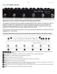
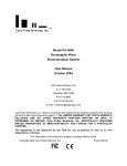
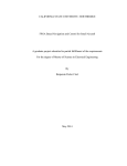
The Neuromorphic Robot version 1.1
User Guide
A Robot building kit and learning materials developed by Iguana Robotics, Inc.
Table of Contents
The Story of SlugBug ………………………………………………………
1
Quick Start Background Tutorials………………………………………….
3
Parts of the SlugBug………………………………………………………..
5
SlugBug Assembly Instructions……………………………………………
6
Programming the SlugBug Neuron Board………………………………..
7
What is a Neuromorphic Engineer…………………………………………
10
Modeling Simple Networks with the Neuron Board……………………...
12
Labsheet for SlugBug Brain Experimentation…………………………….
18
User Information and Warranty ……………………………………………..
19
The Idea…
Dr. M. Anthony Lewis, a former NASA engineer, had an idea to create an inexpensive
electronic board that would model biological neurons. He thought this board could be
used to teach children and young adults about neuroscience.
The Neuron Emulator Board
Liudmila Yafremava, PhD candidate from the
University of Illinois, was studying the Tritonia Sea Slug
and decided to use its brain as a model for a Neuron
Emulator Board. She built the Neuron Emulator on a
breadboard out of simple electronic components.
The Robot
J. Jill Rogers, a school teacher, was
working at Iguana Robotics, Inc. One
afternoon she built a robot out of two
servos, wire and some glue. For fun
she added antenna, wings and other
decorations.
SlugBug prototype 1
The robot was then hooked up to the Neuron board and… It came to life!
Iguana Robotics, Inc.
Copyright 2005
1
What is special about the SlugBug?
The part of the brain responsible for movement in a Tritonia Sea Slug was reverse
engineered and used as a model for the SlugBug brain. In other words, scientists
studied the wet brain of the sea slug pictured below and used it as a “plan” or “map” for
the SlugBug robot brain. The robot is called a “Bug” because it looks a bit like one as it
crawls along the floor. This is how the SlugBug gets its unusual name.
Tritonia Sea Slug
Tritonia Brain
SlugBug Brain
What can you do with the SlugBug?
First build your SlugBug body and then design the
SlugBug
neural network connections for the robot’s brain. The
SlugBug’s brain has four analog neurons that can be
adjusted with a push of a button. Plug your computer speakers into the jacks on the
wide end of the brain and listen to the neurons fire. As you experiment, observe how
neuron firing rate directly affects the SlugBug’s behavior. Then make adjustments that
cause your robot to walk faster, or to move in a more graceful way.
For a quick start, read through pages 3 through 9 of this user manual. Once you get the
hang of adjusting the various neuron parameters and decide on a leg shape you like,
you will want to learn more about the exciting field of Neuromorphic Engineering.
Additional information about neuron function, and the science behind the SlugBug brain
can be found in the remaining pages of this manual.
SlugBug is great for multi-disciplinary study focusing on neuroscience, electronics,
mechanical engineering and/or robotics.
A teachers guide complete with lesson plans and learning standards will soon be
available online at www.slugbugrobot.com
Iguana Robotics, Inc.
Copyright 2005
2
Quick Start Background tutorials
All scientists must study various subjects in order to be good at what they do. If
you want to really understand your SlugBug and get the most out of its amazing brain
you will need to learn a little bit about neurons (brain cells) and electronics. Once you
have a basic understanding of these two topics we will show you how the neurons in the
SlugBug’s brain behave similarly to those of a biological brain.
Neuron Physiology
A neuron is a type of cell that is found in the brain, spinal cord and the nerves that are
throughout your body. Neurons are much like other cells in your body since they have a
nucleus, cytoplasm, mitochondria and a cell membrane etc.
Stimulus
However, a neuron is unique when compared to other cells
since it communicates by sending electrochemical impulses.
This is how it works:
1. The system begins with sensory input called a
stimulus. For example, the neurons in your fingertips
receive a stimulus when you touch a hot stove.
2. The stimulus arrives at the branch-like dendrites and
positively charged ions rush through the dendrites
and into cell body.
3. The cell body starts at a resting potential of about
–70mV. As ions rush in, the cell body becomes more
positively charged and achieves firing threshold at
about -55mV. (mV stands for millivolt)
4. Once it reaches firing threshold the axon hillock fires
an action potential (a spike) and sends a
electrochemical message down the axon, out the
synaptic terminals and on to the next neuron.
5. This process continues from neuron to neuron until
the message reaches the brain and you pull your
hand away from the stove.
A great place to learn more about the neurons and
the brain sciences is the at this website:
http://faculty.washington.edu/chudler/neurok.html
Iguana Robotics, Inc.
Copyright 2005
3
Dendrites
Cell Body
Axon
Hillock
Axon
Synaptic Terminals
Basic Electronics
Electricity is a flow of tiny particles called electrons. These electrons flow through wires
and electronic devices much like water in a river. When an electronic device such as a
television or compact disk player is turned on, electrons flow thought the various circuits
and components causing the device to behave in a desired way.
An important building block of most electronic devices is an RC circuit. “R” stands for
resistor. A resistor is like a river, allowing electrons to flow through it. “C” stands for
capacitor. A capacitor is like a lake, holding electrons until it is full. This is how an RC
circuit works:
5V
1.
2.
3.
4.
5.
Electricity flows into the system. The
example on the right shows 5volts going
in.
The electrons flow through the resistor
and into the capacitor.
Once the capacitor is full it discharges.
The electrons flow out of the circuit to
“ground” or on to another circuit.
This process repeats from circuit to circuit
causing the electronic device to behave in
a desired way.
SlugBug neurons compared to biological neurons
If you read again about the two systems described above: Neurons and RC circuits, you
will see that there are functional similarities. Neuromorphic Engineers study these
similarities and use this in their electronic designs. Your SlugBug brain has four neurons
that use the RC circuit model. These neurons are all inter-connected in a neural network
with synapses going back and forth between each neuron. The rate of flow and
discharge is controlled by the size of capacitors and resistors used. The very cool thing
about your SlugBug brain is that the flow and discharge rates can be easily adjusted as
you push the programming buttons. These small adjustments in neuron excitation,
inhibition and adaptation affect the movement of the SlugBug: illustrating how neuron
activity directly affects behavior in a biological creature.
Another interesting feature of the SlugBug brain is that you can actually listen to
the neurons emitting spikes when you plug computer speakers into the jacks on the
wide end of the brain. The “pop pop pop” sound you hear is very much like the sound
emitted from a biological neuron when it is probed. Also, when you use an oscilloscope
to probe a neuron on the electronic board it produces traces that are amazingly
biologically accurate. Examples of the spiking output from a SlugBug brain is located on
page 17. The SlugBug brain is as close to a biological brain as can be achieved in
analog RC circuits.
Iguana Robotics, Inc.
Copyright 2005
4
Parts of your SlugBug
Your SlugBug has a few simple parts that when assembled make a walking
robot. Study the picture below and get to know the parts that make SlugBug.
SlugBug
Brain
Round
plastic disk
Plastic
part A
Wire
legs
2 Servo
motors
Plastic
part B
Iguana Robotics, Inc.
Copyright 2005
5
SlugBug Assembly Directions
Follow these directions to assemble your SlugBug. Work together and take turns using the tools
and performing the various tasks. Remember these safety issues: cut wires have sharp edges,
hot glue gun is extremely hot and wire cutters are sometimes known as “finger cutters.”
1.
•
•
•
•
•
•
2.
3.
4.
Check to be certain that your kit has all of the parts you need:
A white (or red) plastic rectangular piece with a square opening at one end, we will
call this part “A”
A plastic rectangular piece with round holes at each end and a long slot along each
side, we will call this part “B”
A roundish plastic disk with a black disk inside
Two Futaba S3003 servo motors
Two pieces of #12 gauge wire, these may be inserted into the plastic parts if your kit
has been used before.
Two screws, if your servos are not in their boxes
Open the Futaba servo boxes, take out the servos, unscrew the X shaped plastic
pieces from the servo shaft, and place everything back in the boxes except: The two
screws and the servos. If your servos have been used
before and are not in a box, ignore this step.
Take a servo and firmly press the shaft through the plastic
piece B and inside the small round, black disk. You may
need to press hard!
The servo shaft has a rotation limit of about 180°. Check to
be certain that the servo will rotate to about 9 o’clock and 3
o’clock. If not, pop the servo off and adjust. Warning: Do
not force the servo beyond its limit of 180° rotation! Screw this servo in place.
3 o’clock
9 o’clock
5.
Hold the second servo and put the red and black wires through part B and slip the
servo snugly in. This will form the back of your robot.
6.
Push one #12 gauge wire leg through the square opening on part A and the other leg
through the roundish plastic disk. Try to keep the wire pieces equal in length. It works
best if you put the wire into a U shape and push both ends of the wire in the holes at
the same time.
7.
Now slip plastic piece A over the front servo, be sure the legs are on the bottom.
8.
Snap the roundish disk onto the shaft of the back servo and screw the servo screw
into the shaft.
Shape and cut legs and feet as desired. Decorate your SlugBug to make it attractive to
other SlugBugs.
Iguana Robotics, Inc.
Copyright 2005
6
Programming the SlugBug Neuron Board
The neuron board consists of four hybrid analog digital neurons, a 4 digit display, 6
programming buttons and 4 analog input ports for programming.
Figure 1. shows a schematic of the computation performed on the Neuron Board. For
clarity, only connection to and from Neuron 1 are shown as well as connections
from Neuron 2.
Two of the four neurons, neuron 1 and neuron 2, are special purpose. They are
integrated and used to drive motor output number one. The firing of neuron 1 causes
the servo motor to move in the CW direction and the firing of neuron 2 causes the servo
to move in the CCW direction. \
Motor 2 is a delayed version of Neuron 1. This phase delay is necessary to ensure that
the trajectory of each leg is roughly elliptical. This is a necessary condition for the
Tildenian walker to progress
forward or backward.
Each neuron receives
inhibitory as well excitatory
S3
S2
input from every other neuron
S1
S4
in the network as well as each
of the 4 sensory inputs.
Therefore, each neuron has a
total of 16 connections (8
inhibitory inputs and 8
N4
N3
excitatory inputs).
Notice that each neuron is
capable of self excitation/self
inhibition.
These 16 parameters define
the neuronal network. In
addition to the parameters
which define the network, a
N1
N2
single parameter is used to
alter the behavior of an
individual neuron. This
parameter is the burst
Σ
Σ
adaptation rate. This rate
determines how quickly
spikes within a burst will
adapt their firing rate. For
∆
example if the adaptation rate
is set to zero, the burst will
contain spikes with a constant
inter-spike intervale (ISI). If
the adaptation rate is greater than zero, the ISI will gradually increase with each spike.
Iguana Robotics, Inc.
Copyright 2005
7
Board Operation
Figure 2 is a drawing of the neuron board showing the 6 switches and the display.
Select Parameter
Scroll UP
Parameter
Power Indicator
Neuron Select
Soft On Switch
Run/Mode Select
Parameter Value
Scroll Down
Program
Turning the board on/off
To turn the board on, press the ‘Soft ON Switch.’ When the board starts properly the
power indicator LED should glow red.
To turn the board off, press “select parameter” and “Program” simultaneously, then
press and release the ‘Run/Mode select button”
When the board comes up, it defaults to a “demo” mode.
Programming the board
,Program mode is entered by holding the “Program” button while pressing and releasing
the “run/mode select button.” At this point, the “Neuron Select” display shows a flashing
“1” indicating that the user is programming neuron ‘1’. To select a different neuron,
scroll up or down using the “scroll up’ and ‘scroll down’ buttons to select neuron ‘1’-‘4’ to
program.
Pressing “select parameter’ will move the flashing display between from Neuron>Parameter->parameter value and back again to “neuron’
Selecting “Parameter” allows you to scroll through the “adaptation” parameter as well as
the inhibitory and excitatory connection from each neuron. Because of the limitations of
the display, the parameters values are encoded according to Table 1. For the meaning
of the parameter values always refer to this table.
Finally, pressing “select” again will allow you to select the strength of the connection or
the adaptation rate. Any one of seventeen values can be selected (0-16 inclusive). To
Iguana Robotics, Inc.
Copyright 2005
8
run your program press and hold the ‘program’ button while you press and release the
“run/Mode select button;”
Parameter A
C
1
2 3 4 5 6 7 8 1. 2. 3. 4. 5. 6. 7. 8.
label on
brain
Parameter Adaptation Charge
Excitatory
Inhibitory
Excitatory
Inhibitory
Rate
From
Neuron
From
Sensor
1
2 3 4 1 2 3 4
1
2
3
4
1
2
3
4
Experimenting with the SlugBug Brain
As you experiment with the brain we suggest you use a table like the one above and fill
in the values of each parameter. Easy to copy lab sheets with multiple tables are
available on page 18 of this user manual. Then run your program and record your
results. Next, make adjustments in a single parameter to see how this affects behavior.
Proceed methodically through many possible settings, recording the results as you go.
After a while you will start to see patterns and understand how the settings for
adaptation, charge rate, excitation and inhabitation for each individual neuron affects
the behavior of the other neurons in the neuronal network as well as the behavior of the
robot. As you work you will come to understand how biological neural networks
generate interesting behaviors.
Iguana Robotics, Inc.
Copyright 2005
9
What is a Neuromorphic Engineer?
Neuromorphic engineers are scientists
who attempt to reverse engineer biological
nervous systems, and then recreate the circuits
they find in silicon or discrete electronic
components. In other words they study biological
brains and use the information they gather to
design artificial control systems for robots and
other electronic devices. This technique of
building biologically similar electronic circuits
was first pioneered by Professor Carver Mead of Caltech in the late 1980's. He named
the technique "Neuromorphic Engineering." Neuromorphic Engineers are adapting the
tricks that the nervous system has come up with over the course of evolution.
With a close relationship to neuroscience, the neuromorphic engineer relies
heavily on the more conventional fields of computer science, mechanical engineering,
biology, kinesiology, zoology and electrical engineering to create tangible models of
their designs. Often times, a computer simulation of a particular design is tried first, to
investigate new neuromorphic designs. Next, robotic devices are frequently built to
illustrate and test the simulated designs a neuromorphic engineer conceives. This
technique called “modeling” allows the neuromorphic engineer to try out ideas on a
robot to see if they really work. Sometimes, a flawless computer simulation behaves
quite differently when run on a physical robot. Scientist in biological fields can better
understand how a biological nervous system works through the close study of a robot
with a neuromorphic design. Neuromorphic engineering is a truly multidisciplinary field
of study.
Neuromorphic engineering has a wide range of applications from adaptive control
of complex systems to the design of smart sensors, vision, speech understanding,
medical prosthesis applications and robotics. Many of the fundamental principles in this
field, such as the use of learning methods and the design of parallel hardware are
inspired by biological systems. However, existing applications are modest and the
challenge of scaling up from small artificial neural networks and designing completely
autonomous systems at the levels achieved by actual
biological systems lies ahead.
In real life robotic applications, a combination of
Biological Systems and Artificial Intelligence seem to be
the best approach for producing a robust, and usable end
product. In fact, the SlugBug brain has analog (as in
biology) and digital (with the use of a PIC) circuits. To
better understand the fields of study Neuromorphic
Engineering encompasses, examine Graphic1.
Iguana Robotics, Inc.
Copyright 2005
10
Graphic 1.
Iguana Robotics, Inc.
Copyright 2005
11
Modeling Simple Networks with Neuron Board 1.0
A biliped membrane as shown in Fig. 1 surrounds neuron cells. The bilipid layer has a
conductive water solution on the outside in the extracellular space, and on the inside, in
the cytoplasm. The bilipid layer itself is an insulator. An insulator surrounded by to
electrodes becomes a capacitor.
A capacitor is a vessel for storing energy in the form of electrical charge. Three factors
Figure 1. Neuron cell Bilipid layer. Shown about is the cross section of a small portion
of a neuron cell. The membrane is formed by lipid molecules with a hydrophilic
(water loving) and hydrophobic (water repelling) end. The cell membrane is a stable
organization of these modules as it keeps the hydrophilic ends pointing to either the
inside or outside of the cell and the hydrophobic ends pointing together.
are important in understanding a capacitor. First, is the size of the capacitor or its
capacitance is measured in Farads. Second, is voltage or a potential difference across
the capacitor. This can be measured with a voltmeter or similar instrument. Third, is the
quanta of charge held separated by the capacitor’s insulator. The rate of change of
charge is current. Voltage, Capacitance, and Current are related by the following
equation:
C mem
Iguana Robotics, Inc.
Copyright 2005
dVmem
= imem
dt
12
(1)
That is, the rate of change of voltage across the membrane is directly proportional to the
current flowing across the membrane and inversely proportional to the size of the
capacitor. The larger the capacitor, the smaller the change in voltage for a given
current; the larger the current the larger the increase in voltage.
Figure 2. Current i flows onto the capacitor. The voltage
increases proportional to the incoming current and inversely
proportional to the capacitance.
In the NeuronBoard, we directly model the membrane capacitance as a physical
capacitor (see Figure 2.).
In a living neuron cell, membrane potential is controlled by the flow of different ion
species across the cell membrane. This flow of ions is driven by an imbalance of ion
species between the extracellular space and the cytoplasm. This asymmetry gives rise
to a driving force for each ion species.
Vi − Vmem
(3)
If a hole were to open in the cell wall, the ion species would move toward equilibrium.
That is, if there is a greater concentration of an ion species in the cytoplasm than the
extracellular space, there would be a net flow of ions from the cytoplasm to the
extracellular space. The flux of ions gives rise to an ion current that in turn results in a
change of voltage across the neuron. These ions are kept out of equilibrium by
appropriate ion pumps embedded in the cell wall.
Embedded in the walls of the cell neuron cell membranes are selective ion channels.
These ion channels are highly selective and permit the passage of single ion species.
Figure 3 shows a crosssection of a cell membrane with ion channels embedded.
Iguana Robotics, Inc.
Copyright 2005
13
Figure 3. Ion Channels are embedded in the bilipid layer. These ion channels
selectively allow passage of ion species, giving rise to a net current flow.
When an ion channel opens, current flows through. How much current is determined by
the specifics of the ion channel, by the number of ion channels that are open and driving
force.
The ease of movement of ions through the channels is measured as conductance. This
is term that is used to describe how easily current flows through a conductive pathway.
Conductance is related to resistance, a measure most often used by electrical
engineers as:
1
(2)
R=
G
Where “R” is resistance and “G” is conductance. Conductance is measured in “mho” or
siemens and resistance is measured in ohms.
To emulate ion channels, we use four resistors in series with four switches. When a
switch is thrown, the given ‘ion’ channel allows current to flow.
What determines current flow onto the capacitor? Current flow is determined by two
factors:
(1) The potential driving force in real cells is the “Nernst reversal potential” of a given ion
species minus the membrane potential.
(2) The conductance of the channel converts the net potential in equation (3) to a
current:
ii = (Vi − Vmem ) ⋅ Gi
(4)
Iguana Robotics, Inc.
Copyright 2005
14
The contribution of each current contributes to the net current flow across the cell
membrane:
imem = i1 + i2 + i3 ...
(5)
dVmem
= i1 + i2 + i3 ...
dt
(6)
Rewriting equation (1) we have:
C mem
dVmem
= (V1 − V mem ) ⋅ G1 + (V2 − Vmem ) ⋅ G 2 + (V3 − Vmem ) ⋅ G 3 + (V 4 − Vmem ) ⋅ G 4
dt
(7)
For simplicity, the NeuronBoard uses two driving potentials: Vss and Vcc (i.e. ground
and the input high input voltage). Although in principle, any voltage could have been
selected for driving potentials, we selected these voltages for ease of implementation in
the electronic design.
The specific equation governing the behavior of the SlugBug is:
dV mem
C mem
= (V ss − V mem ) ⋅ G1 ⋅ S 1 + (V SS − V mem ) ⋅ G 2 ⋅ S 2 + (V cc − Vmem ) ⋅ G 3 ⋅ ⋅S 3 + (V cc − Vmem ) ⋅ G 4 ⋅ S 4
dt
C mem
This equation is shown schematically in figure 4.
We can control the effective conductance my modulating a nominal conductance G1
with a modulated signal S1 . Second, we can allow all similar currents to flow through a
single physical resistor, modulated by the appropriate signal S1 . Thus, instead of
needing 8 neurons for all the excitatory inputs from 4 other neurons and 4 sensory
inputs, we only need a single resistor. This insight vastly simplifies the design of the
board.
Iguana Robotics, Inc.
Copyright 2005
15
Figure 4. Schematic of equation 6.
The channels are activated by changes in voltage (voltage gated activation) or by
neurotransmitters (ligand gated activation).
In Figure 4, we have two parts to our model a synaptic input with excitatory and
inhibitory inputs. These model ligand gated channels that are activated by synapses on
the dendrites arbor or cell body of the neuron.
In addition, the inhibitory resistor has double duty. It also models slow currents which
cause the cell to adapt its firing rate.
We also have two voltage gated channels called “charge” and “discharge.” These model
fast voltage dependent channels of neurons.
Figure 5 shows the complete analog circuit portion of the neuron.
We note that once the neuron fires, an all or nothing action potential is propagated in
essentially a binary fashion. It is easy to model this action with digital circuitry. In the
Neuron board, a traditional CPU is used to route action potentials to their synaptic
destination.
A final and critical refinement in the circuit is in the strength of the synaptic connection
between neurons. In a living system, the strength of a connection could be determined
by the number of target ion channels in a synaptic cleft, the rate of uptake of spent
neurotransmitter, and the magnitude of release of the transmitter.
Iguana Robotics, Inc.
Copyright 2005
16
We summarize this weight process by quickly switching on one of the synaptic switches
for varying lengths of time. A stronger weight would have larger “on” time. This
essentially creates a “virtual” tunable synapse.
In previous implementation of circuits, designers have tried to create variable resistors.
Our approach, the adjustment of switch timing, is elegant and easy to implement,
making the Neuron board a very parsimonious circuit.
Examples of spiking output
The neural circuitry mimics a spiking neuron very well. In figure 5, we show an
oscilloscope trace of two neurons.
Figure 5. Example of two neurons spiking. In this case, neurons are
reciprocally connected with inhibitory synapses. The circuit forms a
simple Central Pattern Generator (CPG) network.
Iguana Robotics, Inc.
Copyright 2005
17
Labsheet for SlugBug Brain Experimentation
Record small changes in the parameters of the brain and make notes on SlugBug
behavior. Run multiple trials to get the best results.
Parameter A
C
1
2 3 4 5 6 7 8 1. 2. 3. 4. 5. 6. 7. 8.
label on
brain
Parameter Adaptation Charge
Excitatory
Inhibitory
Excitatory
Inhibitory
Rate
From
1
2 3 4 1 2 3 4
Neuron
From
1 2 3 4 1 2 3 4
Sensor
Notes:________________________________________________________________
Parameter A
C
1
2 3 4 5 6 7 8 1. 2. 3. 4. 5. 6. 7. 8.
label on
brain
Parameter Adaptation Charge
Excitatory
Inhibitory
Excitatory
Inhibitory
Rate
From
1
2 3 4 1 2 3 4
Neuron
From
1 2 3 4 1 2 3 4
Sensor
Notes:________________________________________________________________
Parameter A
C
1
2 3 4 5 6 7 8 1. 2. 3. 4. 5. 6. 7. 8.
label on
brain
Parameter Adaptation Charge
Excitatory
Inhibitory
Excitatory
Inhibitory
Rate
From
1
2 3 4 1 2 3 4
Neuron
From
1 2 3 4 1 2 3 4
Sensor
Notes:________________________________________________________________
Parameter A
C
1
2 3 4 5 6 7 8 1. 2. 3. 4. 5. 6. 7. 8.
label on
brain
Parameter Adaptation Charge
Excitatory
Inhibitory
Excitatory
Inhibitory
Rate
From
1
2 3 4 1 2 3 4
Neuron
From
1 2 3 4 1 2 3 4
Sensor
Notes:________________________________________________________________
Iguana Robotics, Inc.
Copyright 2005
18
SlugBug User Information and Warranty
Congratulations on purchasing SlugBug the Neuromorphic Robot. The SlugBug Robot
is a new and exciting educational tool that brings state of the art technology to your
school or laboratory. As you work with your robot, let us know how things are going. We
are always looking for ways to improve our product. Please email your ideas for
SlugBug lessons, comments, suggestions and remarks to, [email protected].
The SlugBug is warranted against defects in materials and workmanship for a period of
90 days. This warranty does not cover damage caused by abuse, water or liquid
damage, breakage and shock, or other damage by the user. The user must fill out and
return the warranty information form below within 30 days of purchase to validate this
warranty agreement.
If the SlugBug fails to perform check out the FAQ section on our Website
www.slugbugrobot.com , or email your questions to [email protected].
If your SlugBug is covered under warranty agreement, it will be repaired and returned to
you free of charge. If your SlugBug is not covered under the warranty agreement above,
then you will be notified of repair costs.
(Cut here)
SlugBug Warranty Form
Please print and fill in all information requested
Name_______________________________________
Email_________________________
Organization_________________________________
Date of Purchase________________
Title________________________________________
Phone number__________________
Address_____________________________________
___________________________________________
___________________________________________
SlugBug identification code (This can be found on a small white label on the square PIC in the center of the
brain.)_________________
Mail to:
Iguana Robotics, Inc.
Copyright 2005
19
Alegrobot, Inc.
PO Box 545
Urbana, IL. 61803
Iguana Robotics, Inc.
Copyright 2005
20