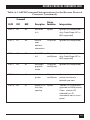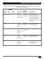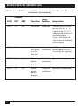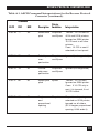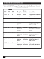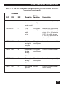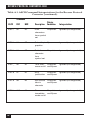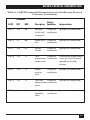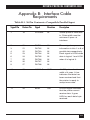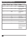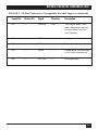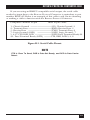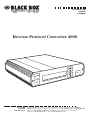
1
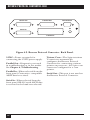
OCTOBER 1995
PC480A
PC480AE
Reverse Protocol Converter 4000
Menu
I/O
List
t
Selec
Alt
CUSTOMER
SUPPORT
INFORMATION
ro
rse P
Reve
000
ter 4
nver
l Co
toco
Order toll-free in the U.S. 24 hours, 7 A.M. Monday to midnight Friday: 877-877-BBOX
FREE technical support, 24 hours a day, 7 days a week: Call 724-746-5500 or fax 724-746-0746
Mail order: Black Box Corporation, 1000 Park Drive, Lawrence, PA 15055-1018
Web site: www.blackbox.com • E-mail: [email protected]
FCC STATEMENT
FEDERAL COMMUNICATIONS COMMISSION
AND
INDUSTRY CANADA
RADIO FREQUENCY INTERFERENCE STATEMENTS
This equipment generates, uses, and can radiate radio frequency energy
and if not installed and used properly, that is, in strict accordance with the
manufacturer’s instructions, may cause interference to radio communication.
It has been tested and found to comply with the limits for a Class A
computing device in accordance with the specifications in Subpart J of
Part 15 of FCC rules, which are designed to provide reasonable protection
against such interference when the equipment is operated in a commercial
environment. Operation of this equipment in a residential area is likely to
cause interference, in which case the user at his own expense will be required
to take whatever measures may be necessary to correct the interference.
Changes or modifications not expressly approved by the party responsible
for compliance could void the user’s authority to operate the equipment.
This digital apparatus does not exceed the Class A limits for radio noise emission from
digital apparatus set out in the Radio Interference Regulation of Industry Canada.
Le présent appareil numérique n’émet pas de bruits radioélectriques dépassant les limites
applicables aux appareils numériques de classe A prescrites dans le Règlement sur le
brouillage radioélectrique publié par Industrie Canada.
TRADEMARKS
UNIX® is a registered trademark of UNIX System Laboratories, Inc.
IBM®, Proprinter®, and IPDS™ are trademarks or registered trademarks
of IBM Corporation.
Epson® is a registered trademark of Seiko Epson Corporation.
Centronics® is a registered trademark of GENICOM Corporation.
Windows™ is a trademark of Microsoft Corporation.
WordPerfect® is a registered trademark of Corel Corporation.
All applied-for and registered trademarks are the property of their respective
owners.
3
INSTRUCCIONES DE SEGURIDAD
NORMAS OFICIALES MEXICANAS (NOM)
ELECTRICAL SAFETY STATEMENT
INSTRUCCIONES DE SEGURIDAD
1. Todas las instrucciones de seguridad y operación deberán ser leídas antes
de que el aparato eléctrico sea operado.
2. Las instrucciones de seguridad y operación deberán ser guardadas para
referencia futura.
3. Todas las advertencias en el aparato eléctrico y en sus instrucciones de
operación deben ser respetadas.
4. Todas las instrucciones de operación y uso deben ser seguidas.
5. El aparato eléctrico no deberá ser usado cerca del agua—por ejemplo,
cerca de la tina de baño, lavabo, sótano mojado o cerca de una alberca,
etc..
6. El aparato eléctrico debe ser usado únicamente con carritos o pedestales
que sean recomendados por el fabricante.
7. El aparato eléctrico debe ser montado a la pared o al techo sólo como
sea recomendado por el fabricante.
8. Servicio—El usuario no debe intentar dar servicio al equipo eléctrico más
allá a lo descrito en las instrucciones de operación. Todo otro servicio
deberá ser referido a personal de servicio calificado.
9. El aparato eléctrico debe ser situado de tal manera que su posición no
interfiera su uso. La colocación del aparato eléctrico sobre una cama,
sofá, alfombra o superficie similar puede bloquea la ventilación, no se
debe colocar en libreros o gabinetes que impidan el flujo de aire por los
orificios de ventilación.
10. El equipo eléctrico deber ser situado fuera del alcance de fuentes de
calor como radiadores, registros de calor, estufas u otros aparatos
(incluyendo amplificadores) que producen calor.
4
INSTRUCCIONES DE SEGURIDAD
11. El aparato eléctrico deberá ser connectado a una fuente de poder sólo
del tipo descrito en el instructivo de operación, o como se indique en el
aparato.
12. Precaución debe ser tomada de tal manera que la tierra fisica y la
polarización del equipo no sea eliminada.
13. Los cables de la fuente de poder deben ser guiados de tal manera que no
sean pisados ni pellizcados por objetos colocados sobre o contra ellos,
poniendo particular atención a los contactos y receptáculos donde salen
del aparato.
14. El equipo eléctrico debe ser limpiado únicamente de acuerdo a las
recomendaciones del fabricante.
15. En caso de existir, una antena externa deberá ser localizada lejos de las
lineas de energia.
16. El cable de corriente deberá ser desconectado del cuando el equipo no
sea usado por un largo periodo de tiempo.
17. Cuidado debe ser tomado de tal manera que objectos liquidos no sean
derramados sobre la cubierta u orificios de ventilación.
18. Servicio por personal calificado deberá ser provisto cuando:
A: El cable de poder o el contacto ha sido dañado; u
B: Objectos han caído o líquido ha sido derramado dentro del
aparato; o
C: El aparato ha sido expuesto a la lluvia; o
D: El aparato parece no operar normalmente o muestra un cambio en su
desempeño; o
E: El aparato ha sido tirado o su cubierta ha sido dañada.
5
REVERSE PROTOCOL CONVERTER 4000
Contents
Chapter
Page
1. Specifications ........................................................................................7
2. Quick Setup...........................................................................................8
2.1 Unpacking.....................................................................................8
2.2 Installation ....................................................................................8
2.3 Configuring the Reverse Protocol Converter Setup
Options..........................................................................................9
3. Introduction..........................................................................................10
3.1 Compatible Printers .....................................................................11
3.2 Unpacking.....................................................................................11
4. Installation ............................................................................................12
4.1 Connecting to the Host and Printer ...........................................15
4.2 Connecting Power ........................................................................15
5. Configuration........................................................................................16
5.1 Using the Front Panel ..................................................................16
5.2 Test Menu .....................................................................................17
5.3 Setup Menu...................................................................................18
5.4 Set Factory Defaults ......................................................................20
5.5 Command Pass-Thru ....................................................................21
6. Troubleshooting ...................................................................................23
6.1 Performing Diagnostics................................................................23
6.2 Reverse Protocol Converter Self-Tests.........................................26
6.3 Problem Resolution Guide ..........................................................29
6.4 Indicated Errors............................................................................29
Appendix A: ASCII Command Translation Table.................................30
Appendix B: Interface Cable Requirements ..........................................49
6
REVERSE PROTOCOL CONVERTER 4000
1. Specifications
Hardware Requirements —
IBM® Proprinter® or Epson FX
printer
Software Requirements — No
special host drivers needed
Emulation — IBM twinax or coax
printer
Systems Supported — ASCII hosts
(PC, PC LAN, UNIX®, AIX®, etc.)
Connectors — (2) DB25 serial,
(1) DB25 parallel, (1) Centronics®
parallel, (1) 9-pin to twinax
V-connector, (1) Power receptacle
Operating Temperature — 32° to
99° F (0° to 37.2° C)
Maximum Relative Humidity —
100%
Power — PC480A: 115 VAC, 60 Hz,
PC480AE: 230 VAC, 50 Hz
Indicators — LCD panel
7
REVERSE PROTOCOL CONVERTER 4000
2. Quick Setup
This Quick Setup Guide is designed
to help you get up and running in a
short amount of time.
2.1 Unpacking
Check the box for freight or water
damage. If any damage is evident,
please contact your carrier
immediately.
The package should contain the
following items:
• Reverse Protocol Converter 4000
• Power supply
• Twinax V-connector and Coax
adapter cable
• This user’s manual
2.2 Installation
The Reverse Protocol Converter
4000 is easy to install and requires
no special tools. Follow these steps to
connect and set up the RPC:
1. Power off the printer.
2. If you decide to use the
Centronics compatible parallel
input, connect a parallel cable to
the “Parallel In” connector on
the Reverse Protocol Converter.
8
If you wish to use the RS-232
serial input, connect a serial
cable to the “Serial In”
connector on the Reverse
Protocol Converter. A
description of the cable
requirements is found in
Appendix B.
3. Connect the 9-pin Twinax
V-adapter or Coax adapter to the
9-pin connector labeled
“Twinax/Coax” on the back
panel of the Reverse Protocol
Converter.
4. For a twinax printer, connect
the twinax cable from the
printer to either one of the
twinax connectors on the
V-connector. For a coax printer,
connect the coax cable from the
printer to the coax connector on
the adapter cable.
5. Plug the wall-mounted
transformer into a standard
110-VAC power outlet.
6. Plug the center post connector
into the 9 VDC receptacle on the
back panel of the Reverse
Protocol Converter.
7. Power on the Reverse Protocol
Converter by pressing the “1-0”
power switch and proceed to
configure the Converter.
REVERSE PROTOCOL CONVERTER 4000
2.3 Configuring the Reverse
Protocol Converter Setup Options
Set the Reverse Protocol Converter
up for operation by using the LCD
front-panel display with its four
option switches. This is done in the
“Setup Menu.” The options available
to use with your twinax or coax
printer are described in Section 5.3.
After connecting the Reverse
Protocol Converter, you can use
your twinax or coax printer just like
an ASCII printer from your PC or
UNIX® host by defining your twinax
or coax printer in the host software
as an IBM® Proprinter® or an Epson®
FX.
9
REVERSE PROTOCOL CONVERTER 4000
3. Introduction
The Reverse Protocol Converter
4000 lets you print ASCII host (PC,
PC LAN, UNIX, AIX, etc.) print jobs
formatted for an IBM Proprinter or
Epson FX printer on an IBM twinax
or coax printer.
It accepts all Epson FX and
Proprinter formatting commands,
then selectively converts and passes
on only the commands that match
the capabilities of the twinax or coax
printer.
For example, the command to
print 12 CPI (Characters Per Inch) is
sent if the Reverse Protocol
Converter is attached to an IBM
twinax 4234, 5219, or 4214 printer,
which is capable of printing 12 CPI,
but is ignored if attached to the
5224, 5225, 5256, or 3262, which
cannot print 12 CPI.
In coax mode, you select whether
the 12 CPI command is to be sent.
This means that you do not have to
10
remove any complex formatting
commands from your documents
before they are printed on the
twinax or coax printer. Appendix A
lists ASCII commands and their
Reverse Protocol Converter
interpretation for your twinax or
coax printer.
The Reverse Protocol Converter is
very simple to use. All configuration
on the twinax side is automatic,
because the twinax printer identifies
its address and printing capabilities
via twinax protocol. For coax
operation, you need to define a few
simple capabilities of your printer.
The ASCII side only requires that
you configure whether Proprinter II
or Epson FX input protocol will be
used by the ASCII host. If the serial
input is used you need to match the
serial input parameters to the host
serial output parameters.
REVERSE PROTOCOL CONVERTER 4000
3.1 Compatible Printers
3.2 Unpacking
The Reverse Protocol Converter in
Twinax mode uses IBM SCS
commands (non IPDS™). The
following is a list of IBM twinax
printers recognized and supported
by the Reverse Protocol Converter:
When you receive the Reverse
Protocol Converter, check the
packaging for water or physical
damage, and notify the carrier
immediately if any damage is
evident.
• 5256 Model 1, 2, 3 (5262
emulating 5256 Model 3)
The package should contain the
following items:
• 5224 Model 1, 2
• Reverse Protocol Converter 4000
• 5225 Model 1, 2, 3, 4
• Power supply
• 4214 Model 2 (4210 emulating
4214 Model 2)
• Twinax output V-connector
• 5219 Model D01, D02 (3812
emulating 5219)
• 4234 Model 2
The Reverse Protocol Converter in
Coax mode uses LU1 IBM SCS
commands. The coax printer needs
to support the LU1 data stream. The
user configures capabilities such as
10, 12, 15 CPI, and LPI settings. The
following printers have been tested
and have functioned properly with
the Reverse Protocol Converter:
• Coax output connector
• This user’s manual
Keep the original packaging in
case you need to move or ship the
Reverse Protocol Converter.
• 3268
• 3287
• 4214 Model 1
• 4224
Compatible third-party twinax
printers should function with the
Reverse Protocol Converter, but
their compliance with IBM twinax or
coax specifications cannot be
assured.
11
REVERSE PROTOCOL CONVERTER 4000
4. Installation
The Reverse Protocol Converter
4000 is easy to install and requires
no special tools. Refer to the
illustrations of the front and back
panels of the Reverse Protocol
Converter (see Figures 4-1 and
4-2), and follow the instructions on
the following pages to connect and
set up the Reverse Protocol
Converter.
Select
Menu
Alt
List
I/O
Figure 4-1. Reverse Protocol Converter: Front Panel.
12
REVERSE PROTOCOL CONVERTER 4000
LCD Display—This displays the
current status of the Reverse
Protocol Converter, and is used to
perform tests and configure the
settings. During operational
“ONLINE” mode, the top line
displays Twinax or Coax mode or
diagnostics mode, then the
operation of the Reverse Protocol
Converter, OFFLINE or ONLINE.
The lower line displays line-sync or
no line-sync with the printer, and
any error status.
Alt—When the operator is displaying
the available options, pressing “Alt”
will “alter” the option.
Menu—Pressing “Menu” moves to
the next “Menu” group if possible.
List—Pressing “List” will “list” the
next setup item.
1-0—Press to power ON the Reverse
Protocol Converter; press again to
power it OFF.
Select—When the Reverse Protocol
Converter is in operating mode,
pressing “Select” will “de-select” or
place the Reverse Protocol
Converter into front panel mode.
While the operator is viewing
different options, pressing “Select”
will “select” the displayed option as
the active option.
13
REVERSE PROTOCOL CONVERTER 4000
Serial Out
Parallel Out
Twinax/Coax
9V
Serial In
Parallel In
Figure 4-2. Reverse Protocol Converter: Back Panel.
9 VDC—Power receptacle for
connecting the 9-VDC power supply.
Parallel Out—Diagnostic port used
in troubleshooting or in test modes.
See Chapter 6, Troubleshooting.
Parallel In—When selected from the
front panel, Centronics® compatible
ASCII data is received.
Serial In—When selected from the
front panel, RS-232 serial ASCII data
is received at the baud rate selected.
14
Twinax/Coax—The 9-pin-to-twinax
V-connector automatically
configures the Reverse Protocol
Converter for connecting a twinax
printer on power-on; the 9-pin coax
connector configures for a coax
printer.
Serial Out—This port is not used on
the Reverse Protocol Converter.
REVERSE PROTOCOL CONVERTER 4000
4.1 Connecting to the Host and
Printer
Take the following steps to connect
the Reverse Protocol Converter to
your ASCII host and twinax or coax
printer.
NOTE
Make sure power is OFF on
the printer and the Reverse
Protocol Converter before
connecting any cables.
1. If Centronics compatible input
is desired, connect a parallel
cable from the 36-pin “Parallel
In” port on the Reverse Protocol
Converter to the parallel port on
the ASCII host (PC, LAN, UNIX,
AIX, etc.).
2. If RS-232 serial input is desired,
connect a serial cable
compatible with the 25-pin
“Serial In” Reverse Protocol
Converter connector and the
serial port of your host
computer. If you are using an
IBM PC compatible serial port,
the serial cables with part
numbers ECM25C, ECM16C,
and ECM12C have been tested
and found to work. Please refer
to Appendix B for cable
requirements.
NOTE
Do not use a parallel adapter
cable longer than 6 feet
(1.8 m), or a serial cable over
25 feet (7.6 m). Your printer
can be located further from
the host since the twinax or
coax cable from the printer
to the Reverse Protocol
Converter can be up to 5000
feet (1524 m) long.
3. Connect the twinax
V-connector or the coax adapter
cable to the 9-pin
“Twinax/Coax” connector on
the back of the Reverse Protocol
Converter.
4. Connect the twinax cable from
the printer to either one of the
twinax connectors on the
V-connector, or the coax cable
from the coax printer to the
Reverse Protocol Converter coax
adapter cable.
5. If you are printing to a coax
printer, follow the user manual
of the printer to set the default
language to U.S./Canada. (This
is necessary only on coax
printers—the Reverse Protocol
Converter will request the
desired language setting on
twinax printers.)
4.2 Connecting Power
Take the following steps to connect
the Reverse Protocol Converter to
power.
1. Plug the wall-mounted
transformer into a standard
power outlet. (The outlet should
supply 115 VAC if you have
model PC480A, or 230 VAC if
you have model PC480AE.)
2. Plug the center post connector
into the 9 VDC receptacle on the
back panel of the Reverse
Protocol Converter.
15
REVERSE PROTOCOL CONVERTER 4000
5. Configuration
After connecting the Reverse
Protocol Converter, you can use
your twinax or coax printer just like
an ASCII printer from your PC or
UNIX host. Simply define your
twinax or coax printer as an IBM
Proprinter or Epson FX printer in
your host software, and send print
jobs in the usual manner. (The
printer definition you use must
match the front-panel “Printer
Emulation” selection.)
NOTE
Some high-capability wordprocessing programs (e.g.,
Windows™ Printer Driver or
WordPerfect®) and desktoppublishing programs may
issue extensive pagepositioning commands that
exceed the capabilities of the
attached twinax or coax
printer. In these cases, we
recommend that you define
your printer as a DOS or
generic printer in the
software to reduce the
complexity of the output
documents.
5.1 Using the Front Panel
The LCD front panel was designed
to be easy for the operator to
configure and use the Reverse
Protocol Converter. To review or
alter the configuration, proceed as
follows:
1. Power on the Reverse Protocol
Converter by pressing the 1-0
switch. A twinax or coax adapter
cable must be attached, or an
error message will be displayed
asking you to attach it. The
Reverse Protocol Converter
should proceed to the
“ONLINE” condition as noted in
the upper right-hand corner of
the display.
2. Put the Reverse Protocol
Converter in the “OFFLINE”
condition by pressing Select.
(Note “OFFLINE” in upper
right-hand corner.)
3. Now the display gives you the
choice of returning to
“ONLINE” operation by pressing
Select or proceeding to use the
menus by pressing Menu. Press
Menu to continue.
4. The display gives you the choice
of entering the “Test Menu” by
pressing List to list items in that
menu, or proceeding to the next
menu by pressing Menu. Press
Menu for setup.
16
REVERSE PROTOCOL CONVERTER 4000
5. The display gives you the choice
of proceeding to the next menu
by pressing Menu or listing the
Setup Menu items by pressing
List. If you want to review or
alter the setup, press List.
6. The first Setup Menu item,
“Printer Emulation,” is displayed
on the top line. The displayed
setting is on the second line. An
asterisk in the first position
indicates that this is the current
active selection.
Press Alt to alter the displayed
selection.
Press Select to make this
displayed option the active
selection. An asterisk will appear
in front of the selection.
Press List to list the next item in
the menu.
Press Menu to exit the setup
menu and go to the next menu.
7. Follow the instructions in #6
above to review and change the
menu item settings that you
desire. When you are satisfied
with your changes, and wish to
exit, press Menu until you reach
the “OFFLINE” display. Pressing
Select will then return the
Reverse Protocol Converter to
normal operation.
5.2 Test Menu
• ASCII Self Test (C/T)—Prints
configuration data and a self-test
to an ASCII parallel printer
attached to the “Parallel Out”
diagnostics port.
• EBCDIC Self Test (C/T)—Prints
the same test as the ASCII selftest, but it is printed on the
attached twinax or coax printer.
This is followed by a characterset “barber pole” pattern until
power is off.
• DIAGNOSTICS TEST (T)—This
test will test all of the twinax
circuitry and then print the
results to an ASCII parallel
printer attached to the “Parallel
Out” port. Refer to Chapter 6,
Troubleshooting, for more
information.
• Hard Loopback Test (C/T)—
The Reverse Protocol Converter
will continuously “poll” itself.
This test is only for a technician
to debug the circuitry.
The following is a list of the LCD
menu options and a brief
explanation of their usage. To
indicate their usage, the following
conventions are used: (C/T) applies
to both twinax and coax, (T) is a
twinax-only option, (C) is a coaxonly option. The default is listed
after the asterisk (*).
17
REVERSE PROTOCOL CONVERTER 4000
5.3 Setup Menu
• Printer Emulation (C/T)
*IBM - PPDS—When there are
differences in the definition
between Epson FX commands
and IBM Proprinter commands,
which definition is used by the
Reverse Protocol Converter?
IBM - PPDS, Proprinter II
command definitions
EPSON - FX, Epson ESC/P
9-pin printer commands
*Default settings
• Diagnostic Mode (C/T) *Off—
This turns OFF or ON the
diagnostic print mode that prints
to an ASCII parallel printer
attached to the “Parallel Out”
diagnostic port all actions of the
Reverse Protocol Converter.
Refer to Chapter 6,
Troubleshooting, for more
information.
• ASCII Character Set (C/T) *PC
set 2 - CP437—The received
ASCII characters are defined as
either:
Code Page 850
PC Set 2 - CP437
• Non-busy on Commands (T)
*Normal—The twinax protocol
requires printers to report busy
after a command is received.
Some faster IBM printers and
some third-party printers do not
do this. You can disable the
Reverse Protocol Converter’s
error checking on this function
if required.
• Non-busy on Data (T)
*Normal—The twinax protocol
requires printers to report busy
after any data is received. Some
faster IBM printers and some
third-party printers do not do
this. You can disable the Reverse
Protocol Converter’s error
checking on this function if
required.
• Fix MPP on CPI change (C/T)
*Yes fix MPP with CPI—IBM
printers maintain a MPP
(Maximum Print Position) even
when the CPI (Characters Per
Inch) changes. If you had been
printing in 10 CPI, the MPP
would have been 132. If the CPI
changes to 15 CPI the MPP
would remain at 132, even
though the printer could print
198 characters. The Reverse
Protocol Converter can adjust
the MPP to its maximum
amount on every CPI change.
Yes FIX MPP with CPI
No change CPI only
18
REVERSE PROTOCOL CONVERTER 4000
• Sheet Feed Commands (C/T)
*Not Supported—If your IBM
printer supports sheet-feed
commands, you can select them,
or disable them if no sheet
feeder is used. The sheet-feed
commands are used as bin
selection on coax and twinax
laser printers.
Twinax:
Coax:
Not Supported
Supported
Not Supported
Use FC byte (the
4028 uses this
method)
Use SD byte (the
3912 uses this
method)
*Default settings
• Fix Hor. Pos. on CPI (C/T)
*Yes—“Fix Horizontal Position
when CPI changes.” If the ASCII
command changes CPI in the
middle of a line, such as at print
position 60, the IBM printer
treats it as 6 inches at 10 CPI and
4 inches at 15 CPI. Overprints
and gaps can result. The Reverse
Protocol Converter can adjust
the printer to better match what
the ASCII printer does.
• Printer CPI support (C) *Only 10
CPI—For coax printers, the
operator needs to select the CPI
support available on the coax
printer. (The Reverse Protocol
Converter reads the CPI support
automatically with twinax
printers.)
Only 10 CPI, (Printers with only
10 CPI: 3287, 3268),
10 and 15 CPI, (Printers that
support 10 and 15 CPI):,
10 12 and 15 CPI, (Printers that
support 10, 12, and 15 CPI:
4224, 4234)
• PPM commands for NLQ (C)
*Disabled—Select the type of
command to control r your coax
printer.
Disabled: ignore NLQ, or no
printer support
Enabled 4214: Two-type,
Draft/NLQ as in 4214
Enabled 4224/30/34, Threetype, Draft/Text/NLQ, as used
in 4224, 4230 and 4234
• Send LF for ESC J (C/T)
*Disabled—ESC J can be used to
move the ASCII printing down
x/216 of an inch. Twinax and
coax printers cannot do this. You
can select how an ESC J will be
treated.
Enabled, sends a Line Feed(LF)
when ESC J is received
Disabled, ignores any ESC J
received
• Change CR to NL (C/T)
*Disabled—This is an “Auto
Feed” function. Some ASCII jobs
expect the printer to do a New
Line (NL=CR + LF) when a CR
(Carriage Return) is received.
You can enable or disable this
function.
19
REVERSE PROTOCOL CONVERTER 4000
• LPI commands to 5256 (T)
*Normal 5256—A true 5256
printer will halt and report an
error if an LPI command is
received. Some printers that
report to the host as a 5256, such
as the 5262, can receive LPI
commands. You can select the
Reverse Protocol Converter to
send LPI commands, or you can
select a normal 5256 without LPI
commands.
• UNIX LF (LF=NL) (C/T)
*Disabled—UNIX and other
hosts expect Line Feed (LF) to
position to the start of the next
line. But LF is a New Line (NL)
function in IBM. You can enable
this feature so that the printer
works the way a UNIX host
expects; or you can disable it, so
that an ASCII LF sends an
EBCDIC LF.
• PC support +5 fix (C/T)
*Disabled—IBM PC Support has
an error of 5 print positions
when there is a CPI change in
the middle of the line. To
correct this, the Reverse
Protocol Converter has this
feature. When the feature is
enabled, and the “Fix Hor. Pos.
on CPI” option is enabled, the
Reverse Protocol Converter will
adjust 5 positions further on the
Horizontal fix.
20
• Command Pass Thru (CPT)
(C/T) *Enabled—You can
enable or disable the Command
Pass-Thru feature, as explained
below. This is useful if the
Twinax or Coax printer has a
command-passthrough feature
that you wish to use, and not
have the Reverse Protocol
Converter intercept it.
• Input Data Source (C/T)
*Parallel—Select RS-232 serial or
Centronics compatible parallel.
• Input Baud Rate (C/T) *9600—
Select from: 38.4K, 19.2K, 9600,
4800, 2400, 1200, 600, 300
• Parity (C/T) *None—Select
from: Odd, Even, None
• Data Bits (C/T) *8—Select
from: 8 or 7
• Stop Bits (C/T) *1—Select from:
1 or 2
*Default settings
5.4 Set Factory Defaults
Pressing Select will restore the
optional settings to the factory
default selections.
REVERSE PROTOCOL CONVERTER 4000
5.5 Command Pass-Thru
If you are familiar with EBCDIC
twinax printer commands, you can
use the Reverse Protocol Converter’s
Command Pass-Thru feature to
access all of the built-in features of a
printer, even if those features are
not normally available through the
ASCII host software. You can insert
printer-specific command sequences
into the data sent to the twinax or
coax printer from the host.
The Reverse Protocol Converter
recognizes these special sequences
and “passes the command through”
to the printer. The steps below
describe how to use Command PassThru.
4. Move the cursor to the point in
the text that you want to change
the print feature back to. Enter
the delimiter, the new printer
command, and then the
delimiter again.
For example:
2B D2 04 29 00 0F is the
command in EBCDIC
hexadecimal code for 15 CPI
printing on printers that support
it. 2B D2 04 29 00 0A is the
command in hexadecimal for 10
CPI printing. So, to begin 15 CPI
printing, enter the command as
follows:
&%2B D2 04 29 00 0F&%
1. Find the command for the print
feature in the printer’s manual.
Then, to change printing back
to 10 CPI, enter:
2. Convert the printer command to
EBCDIC hexadecimal.
&%2B D2 04 29 00 0A&%
3. Place the Command Pass-Thru
delimiter, &%, in the document
at the point where you want the
feature to take effect. This
signals the start of the print
feature. Enter the printer
command in EBCDIC
hexadecimal code, then enter
the delimiter, &%, again.
Only characters from 00 to FF are
recognized (letters must be in upper
case).
Errors in the Command Pass-Thru
sequence will cause the Reverse
Protocol Converter to ignore the
command and resume printing at
the point where the error occurred.
You may enter a space between
hexadecimal code pairs to make
the command easier to read, but
do not put spaces between the
delimiter and the hexadecimal
characters.
21
REVERSE PROTOCOL CONVERTER 4000
Command Pass-Thru may change
horizontal spacing. Although the
command is displayed on the screen,
the Reverse Protocol Converter
treats it as a command and does not
print it. If part of the sequence is
printed, you have made an error in
entering the codes; check your
document and make sure you are
using the correct format and
EBCDIC hexadecimal characters.
Avoid sending codes that would
move the print position during
22
Command Pass-Thru. Since the
Reverse Protocol Converter does not
process these commands, it cannot
keep track of the changes in print
position; this may affect the position
of following characters and page
layout.
You can also send the Reverse
Protocol Converter Command PassThru strings to the printer by typing
them on the ASCII host screen and
pressing the screen-print key.
REVERSE PROTOCOL CONVERTER 4000
6. Troubleshooting
This chapter provides information to
help analyze and solve possible
problems with the Reverse Protocol
Converter.
Before you call for technical
support, perform the diagnostic tests
described below. Then look for the
problem in the tables in this chapter
and try the suggested actions to solve
it. If you still have problems, contact
Technical Support and have the
following information ready:
• Serial number of Reverse
Protocol Converter
• Type of ASCII host
• Date of purchase of Reverse
Protocol Converter
• Model of twinax or coax printer
• Description of problem error
message
• Diagnostic results
6.1 Performing Diagnostics
Reverse Protocol Converter
diagnostics will provide you with
information on any error conditions
identified by the Reverse Protocol
Converter, as well as documentation
of its operation.
• Press Menu twice to get to “Setup
Menu.”
• Press List twice to get to
“Diagnostic Mode” option.
• Press Alt to alter selection from
“*Off” to “On.”
• Press Select to activate the
selection, which now appears as
“*On.”
• Press Menu to return to the
“OFFLINE” selection.
• Press Select to return to
Diagnostics “ONLINE”
operation.
4. To end Diagnostics mode,
repeat steps in #3 above, but
change “Off” and “On.” This
setting is constantly monitored,
and the function can be
activated even while a document
is printing to capture a problem
later in documents. (Allow for a
delay in printing caused by the
size of the ASCII printer’s
buffer.)
A list of statements documenting
the sequence of the operations and
conversions performed by the
Reverse Protocol Converter prints. A
sample printout from the diagnostic
port is shown on the next page.
NOTE
Activating the diagnostic
port significantly slows
down printing speed and
may cause the Line Sync
LED on the twinax printers to
flash.
23
REVERSE PROTOCOL CONVERTER 4000
Twinax Driver (c) I-O Rev A07 1-21-94
Communication established - at Address 3
ID - 2D = 5219D01
0
:
1
:
2
2D0802D02002C002C0402C042C083C03C0
B1310B2490AB62CB8300B222B124441401
JaK
F H
Bâ Ad D {
0D 0A 41 42 43 44 46 56 47 48 49 4A 4B 4C 4D 4E 4F 50 51 52 53 54 55 56 57 58
59 5A 20 31 32 33 34 35 36 37 38 39 30 20 20 20 20 20 20 20 20 20 20 20 20 20 20
20 20 20 20 20 20 20 20 20 20 20 20 20 20 20 20 20 20 20 20 20 20 20 20 20 20 20
20 20 20 20 0D 0A 41 42 43 44 45 56 57 58 49 4A 4B 4C 4D 4E 4F 50 51 52 53 54
55 56 57 58 59 5A 20 31 32 34 35 36 37 38 39 30 20 20 20 20 20 20 20 20 20 20 20
20 20 20 20 20 20 20 20 20 20 20 20 20 20 20 20 20 20 20 20 20 20 20 20 20 20 20
20 20 20 20 20 20 20 20 0D 0A 41 42 43 44 45 56 57 48 49 4A 4B 4C 4D 4E 4F 50
51 52 53 54 55 56 57 58 59 5A 20 31 32 33 34 35 36 37 38 39 30 20 20 20 20 20 20
20 20 20 20 20 20 20 20 20 20 20 20 20 20 20 20 20 20 20 20 20 20 20 20 20 20 20
20 20 20 20 20 20 20 20 20 20 20 20 0D 0A 41 42 43 44 45 46
0
:
1
:
2
:
3
:
02CCCCCCCCCDDDDDDDDDEEEEEEEEE4FFFFFFFFF444444444444444444
D5123456789123456789234567890123456789000000000000000000000000000000
ABCDEFGHIJKLMNOPQRSTUVWXYZ 1234567890
4
:
5
:
6
:
7
:
444444444444444444402CCCCCCCCCDDDDDDDDDEEEEEEEEE4FFFFFFFF
0000000000000000D512345678912345678923456789123456789000000000000000
ABCDEFGHIJKLMNOPQRSTUVWXYZ 1234567890
Figure 6-1. Sample Twinax Diagnostics Printout.
24
REVERSE PROTOCOL CONVERTER 4000
COAX Driver (c) 1994 SDE Rev 1.00 12-06-94
Communication established with printer
Printer Registers.
Addr
0 1 2
0000
-20 04 00
0010-00 06 01 00
0020-00 00 00 00
0030-00 00 00 00
0040-00 00 00 00
3
00
00
00
00
00
4
00
0D
00
00
00
5
00
03
00
00
00
6
00
00
00
00
00
7
00
00
00
00
00
8
00
00
00
00
00
9
00
00
00
00
00
A
01
00
00
00
00
B
40
00
00
00
00
C
15
00
00
00
00
D
10
00
00
00
00
E
10
00
00
00
00
F
00
00
00
00
00
Print Buffer.
Addr
0 1 2 3 4 5 6 7 8 9 A B C D E D
0010-2B
C6 02 0C 2B C2 02 42 2B C1 02 84 0D .F...B..A.d.
ASCII data.
31 32 33 34 35 36 37 38 39 30 31 32 33 34 35 36 37 38 39 30 31 32 33 34 35 36
37 38 39 30 31 32 33 34 35 36 37 38 39 30 31 32 33 34 35 36 37 38 39 30 31 32
33 34 35 36 37 38 39 30 31 32 33 34 35 36 37 38 39 30 31 32 33 34 35 36 37 38
39 30 31 32 33 34 35 36 37 38 39 30 31 32 33 34 35 36 37 38 39 30 31 32 33 34
35 36 37 38 39 30 31 32 33 34 35 36 37 38 39 30 31 32 33 34 35 36 37 38 39 30
31 32 0D 0A 30 32 58 58 58 58 58 58 58 58 58 58 58 58 58 58 58 58 58 58 58 58
58 58 58 58 58 58 58 58 58 58 58 58 58 58 58 58 58 58 58 58 58 58 58 58 58 58
58 58 58 58 58 58 58 58 58 58 58 58 58 58 58 58 58 58 58 58 58 58 58 58 58 58
58 58 58 58 58 58 58 58 58 58 58 58 58 58 58 58 58 58 58 58 58 58 58 58 58 58
58 58 58 58 58 58 58 58 58 58 58 58 58 58 58 58 58 58 58 58 58
Printer Registers.
Addr
0 1 2
0000 -20 04 00
0010 -00 06 01
0020 -00 00 00
0030 -00 00 00
0040 -00 00 00
3
00
00
00
00
00
4
00
00
00
00
00
5
00
FE
00
00
00
6
00
03
00
00
00
7
00
00
00
00
00
8
00
00
00
00
00
9
00
00
00
00
00
A
01
00
00
00
00
B
40
00
00
00
00
C
15
00
00
00
00
D
10
00
00
00
00
E
10
00
00
00
00
F
00
00
00
00
00
Print Buffer.
Addr
0 1 2 3 4 5 6 7 8 9 A B C D E F
0100 -F1 F2 F3 F4 F5 F6 F7 F8 F9 F0 F1 F2 F3 F4 F5 F6 1234567890123456
0110 -F7 F8 F9 F0 F1 F2 3F F4 F5 F6 F7 F8 F9 F0 F1 F2 7890123456789012
0120 -F3 F4 F5 F6 F7 F8 F9 F0 F1 F2 F3 F4 F5 F6 F7 F8 3456789012345678
0130 -F9 F0 F1 F2 F3 F4 F5 F6 F7 F8 F9 F0 F1 F2 F3 F4 9012345678901234
0140 -F5 F6 F7 F8 F9 F0 F1 F2 F3 F4 F5 F6 F7 F8 F9 F0 5678901234567890
0150 -F1 F2 F3 F4 F5 F6 F7 F8 F9 F0 F1 F2 F3 F4 F5 F6 1234567890123456
0160 -F7 F8 F9 F0 F1 F2 F3 F4 F5 F6 F7 F8 F9 F0 F1 F2 7890123456789012
0170 -F3 F4 F5 F6 F7 F8 F9 F0 F1 F2 F3 F4 F5 F6 F7 F8 3456789012345678
0180 -F9 F0 F1 F2 0D 25 F0 F2 E7 E7 E7 E7 E7 E7 E7 E7 9012..02XXXXXXX
0190 -E7 E7 E7 E7 E7 E7 E7 E7 E7 E7 E7 E7 E7 E7 E7 E7 XXXXXXXXXXXX
01A0 -E7 E7 E7 E7 E7 E7 E7 E7 E7 E7 E7 E7 E7 E7 E7 E7 XXXXXXXXXXXX
01B0 -E7 E7 E7 E7 E7 E7 E7 E7 E7 E7 E7 E7 E7 E7 E7 E7 XXXXXXXXXXXX
01C0 -E7 E7 E7 E7 E7 E7 E7 E7 E7 E7 E7 E7 E7 E7 E7 E7 XXXXXXXXXXXX
01D0 -E7 E7 E7 E7 E7 E7 E7 E7 E7 E7 E7 E7 E7 E7 E7 E7 XXXXXXXXXXXX
01E0 -E7 E7 E7 E7 E7 E7 E7 E7 E7 E7 E7 E7 E7 E7 E7 E7 XXXXXXXXXXXX
01F0 -E7 E7 E7 E7 E7 E7 E7 E7 E7 E7 E7 E7 E7 E7
XXXXXXXXXX
Figure 6-2. Sample Coax Diagnostics Printout.
25
REVERSE PROTOCOL CONVERTER 4000
6.2 Reverse Protocol Converter
Self-Tests
The front panel is used to perform
self-tests. A complete description of
front-panel use is given in Chapter 5,
Configuration.
To enter the front-panel Test
Menu, do the following:
• With the Reverse Protocol
Converter in “ONLINE” mode
(ONLINE upper right), press
Select to take “OFFLINE.”
• Press Menu to get to “Test
Menu.”
To perform a self-test, press List
twice to display the EBCDIC self-test
option, then press Select to select
the test. The results of an internal
self-test, the software version, and
the setup selections are
printed out on the attached twinax
or coax printer. An example of the
self-test printout is shown on the
next pages.
If you wish to test the diagnostic
port, press List once to display the
ASCII self test option, then press
Select to select the test. The same
self-test printout as above is printed
on an ASCII parallel printer
connected to the diagnostic port.
26
If you wish to test twinax
communications (this test is
unavailable for coax), disconnect the
twinax cable from the twinax
V-connector (connected to the
Reverse Protocol Converter’s
“Twinax/Coax” port), but leave the
“V” cable connected to the Reverse
Protocol Converter. Press List three
times to display the DIAGNOSTICS
TEST option. Press Select to select
the test. A comprehensive diagnostic
self-test is performed and “Test
Complete” or a description of errors
identified is sent to a parallel printer
attached to the diagnostic port.
NOTE
If the twinax cable is not
disconnected, you may
receive the error message
“Input Data Available Bit
Bad.”
The final test is for use by a repair
technician with an oscilloscope. A
twinax or coax loopback signal is
generated. Press List three times in
coax mode or four times in twinax
mode to display the Hard Loopback
test option, then press Select to
select the test.
REVERSE PROTOCOL CONVERTER 4000
TWINAX Driver (c) I-O Rev 1.00 1-21-94
Configuration Switch Selections:
1Printer Emulation . . . . . . . . . . . . . . . . . . :
2Debug Mode. . . . . . . . . . . . . . . . . . . . . . .:
3ASCII Character Set . . . . . . . . . . . . . . . . :
4Test BUSY on Twinax commands. . . . . .:
5Test BUSY on Twinax data. . . . . . . . . . . :
6Adjust MPP on CPI changes . . . . . . . . . . :
7Send Sheet Feeder Commands. . . . . . . . :
8Adjust Hor. Pos. on CPI changes . . . . . . :
IBM -PPDS
Off
PC Set 2 - CP437
Normal
Normal
Change MPP on CPI changes
Off
Off
RAM OK
ROM OK
ASCII cp437 to EBCDIC Translate Table
00 10 20 30 40 50 60 70 80 90 A0 B0 C0 D0 E0 F0
0:
00 00 40 F0 7C D7 79 97 68 71 45 40 40 40 40 40
1:
00 00 4F F1 C1 D8 81 98 DC 9C 55 40 40 40 59 8F
2:
00
7F F2 C2 D9 82 99 51 9E CE 40 40 40 40 DA
3:
00 00 7B F3 C3 E2 83 A2 42 CB DE BB 40 40 40 8D
4:
00
5B F4 C4 E3 84 A3 43 CC 49 40 40 40 40 40
5:
00 B5 6C F5 C5 E4 85 A4 44 CD 69 40 40 40 40 40
6:
00 00 50 F6 C6 E5 86 A5 47 DB 9A 40 40 40 A0 40
7:
2F 00 7D F7 C7 E6 87 A6 48 DD 9B 40 40 40 40 40
8:
00 4D F8 C8 E7 88 A7 52 DF AB 40 40 40 40 90
9:
00 00 5D F9 C9 E8 89 A8 53 EC 00 40 40 40 40 B3
A:
00 5C 7A D1 E9 91 A9 54 FC BA 40 40 40 40 4B
B:
4E 5E D2 4A 92 C0 57 B0 B8 40 40 40 8C 40
C:
00 6B 4C D3 E0 93 6A 56 B1 B7 40 40 40 40 40
D:
00 60 7E D4 5A 94 D0 58 B2 AA 40 40 40 80 EA
E:
00 4B 6E D5 5F 95 A1 63 B3 8A 40 40 40 40 40
F:
00 61 6F D6 6D 96 00 67 B4 8B 40 40 40 40 40
ASCII cp850 to EBCDIC Translate Table
00 10 20 30 40 50 60 70 80 90 A0 B0 C0 D0 E0 F0
0:
00 00 40 F0 7C D7 79 97 68 71 45 40 40 8C EE CA
1:
00 00 4F F1 C1 D8 81 98 DC 9C 55 40 40 AC 59 8F
2:
00
7F F2 C2 D9 82 99 51 9E CE 40 40 72 EB BF
3:
00 00 7B F3 C3 E2 83 A2 42 CB DE BB 40 73 ED B9
4:
00
5B F4 C4 E3 84 A3 43 CC 49 40 40 74 CF B6
5:
00 B5 6C F5 C5 E4 85 A4 44 CD 69 65 40 40 EF B5
6:
00 00 50 F6 C6 E5 86 A5 47 DB 9A 62 46 75 A0 40
7:
2F 00 7D F7 C7 E6 87 A6 48 DD 9B 64 66 76 AE 9D
8:
00 4D F8 C8 E7 88 A7 52 DF AB AF 40 77 8E 90
9:
00 00 5D F9 C9 E8 89 A8 53 EC AF 40 40 40 FE BD
A:
00 5C 7A D1 E9 91 A9 54 FC BA 40 40 40 FB B3
B:
4E 5E D2 4A 92 C0 57 B0 B8 40 40 40 FD DA
C:
00 6B 4C D3 E0 93 6A 56 B1 B7 40 40 40 8D FA
D:
00 60 7E D4 5A 94 D0 58 80 AA B0 40 6A AD EA
E:
00 4B 6E D5 5F 95 A1 63 B3 8A B2 40 78 BC 40
F:
00 61 6F D6 6D 96 00 67 B4 8B 40 9F 40 BE 40
Figure 6-3. Sample Twinax Self-Test Printout.
27
REVERSE PROTOCOL CONVERTER 4000
COAX Driver (c) 1994 SDE Rev 1.00 12-06-94
Active Configuration Selections:
Printer Emulation:............................:
Debug Mode......................................:
ASCII Character Set..........................:
Adjust MPP on CPI changes.............:
CPI support on printer.....................:
Send PPM commands for NLQ........:
Command-Pass-Thru (CPT) enabled:
Send a LF when ESC J received.......:
Change CR into NL..........................:
UNIX LF (Change LF into NL).......:
PC Support +5 position fix..............:
Input Data Source............................:
IBM — PPDS
Off
PC Set 2 — CP437
Change MPP on CPI changes
Only 10 CPI
Disabled
Enabled
Off
Off
Off
Off
Parallel
RAM OK
ROM OK
ASCII cp437 to EBCDIC Translate Table
00 10 20 30 40 50 60 70 80 90 A0 B0 C0 D0 E0 F0
0:
00 00 40 F0 7C D7 79 97 68 71 45 40 40 40 40 40
1:
00 00 5A F1 C1 D8 81 98 DC 9C 55 40 40 40 59 8F
2:
00
7F F2 C2 D9 82 99 51 9E CE 40 40 40 40 DA
3:
00 00 7B F3 C3 E2 83 A2 42 CB DE 4F 40 40 40 8D
4:
00
5B F4 C4 E3 84 A3 43 CC 49 40 40 40 40 40
5:
00 B5 6C F5 C5 E4 85 A4 44 CD 69 40 40 40 40 40
6:
00 00 50 F6 C6 E5 86 A5 47 DB 9A 40 40 40 A0 40
7:
2F 00 7D F7 C7 E6 87 A6 48 DD 9B 40 40 40 40 40
8:
00 4D F8 C8 E7 88 A7 52 DF AB 40 40 40 40 40
9:
00 00 5D F9 C9 E8 89 A8 53 EC 00 40 40 40 40 B3
A:
00 5C 7A D1 E9 91 A9 54 FC B0 40 40 40 40 4B
B:
4E 5E D2 BA 92 C0 57 4A B8 40 40 40 8C 40
C:
00 6B 4C D3 E0 93 6A 56 B1 B7 40 40 40 40 40
D:
00 60 7E D4 BB 94 D0 58 B2 AA 40 40 40 80 EA
E:
00 4B 6E D5 B0 95 A1 63 B3 8A 40 40 40 40 40
F:
00 61 6F D6 6D 96 00 67 B4 8B 40 40 40 40 40
ASCII cp850 to EBCDIC Translate Table
00 10 20 30 40 50 60 70 80 90 A0 B0 C0 D0 E0 F0
0:
00 00 40 F0 7C D7 79 97 68 71 45 40 40 8C EE CA
1:
00 00 5A F1 C1 D8 81 98 DC 9C 55 40 40 AC 59 8F
2:
00
7F F2 C2 D9 82 99 51 9E CE 40 40 72 EB BF
3:
00 00 7B F3 C3 E2 83 A2 42 CB DE 4F 40 73 ED B9
4:
00
5B F4 C4 E3 84 A3 43 CC 49 40 40 74 CD B6
5:
00 B5 6C F5 C5 E4 85 A4 44 CD 69 65 40 40 EF B5
6:
00 00 50 F6 C6 E5 86 A5 47 DB 9A 62 46 75 A0 40
7:
2F 00 7D F7 C7 E6 87 A6 48 DD 9B 64 66 76 AE 9D
8:
00 4D F8 C8 E7 88 A7 52 DF AB AF 40 77 8E 90
9:
00 00 5D F9 C9 E8 89 A8 53 EC AF 40 40 40 FE BD
A:
00 5C 7A D1 E9 91 A9 54 FC 5F 40 40 40 FB B3
B:
4E 5E D2 BA 92 C0 57 70 B8 40 40 40 FD DA
Figure 6-4. Sample Coax Self-Test Printout.
28
REVERSE PROTOCOL CONVERTER 4000
6.3 Problem Resolution Guide
Use the following information as a
guide to possible solutions to
common problems with the Reverse
Protocol Converter or the twinax
printer.
• Solution: Print out a self-test to
determine whether Epson or
IBM mode is selected and if the
Code Page 437 or Code Page
850 character is selected. Verify
that it is appropriate for the
printer driver selected in the
software, and reset the frontpanel settings if they are not.
• Problem: Twinax printer does not
indicate “busy” when data
received and the Major Error
message is displayed.
6.4 Indicated Errors
• Probable Cause: Some twinax
printers from makers other than
IBM normally do not indicate
“busy” after receiving a
command or data.
Some errors will be displayed on the
LCD front panel of the Reverse
Protocol Converter (see Figure
4-1). The errors involving the printer
are as follows.
• Solution: Activate the diagnostic
port to determine if this is the
problem. If it is, select “No Error
Check” from the front panel
“Non-Busy” options to instruct
the Reverse Protocol Converter
to ignore the error; it will not
affect the printing.
• Parity Err—A parity error is
generally caused by defective
cabling or poor connectors to
the printer. If the error occurs
frequently, check the cables for
problems. To clear the error,
press the Select button to take
the Reverse Protocol Converter
“OFFLINE” and press Select
again to return to “ONLINE.”
• Problem: Vertical spacing of the
printing is not consistent.
• Probable Cause: The vertical
spacing commands are too
complex for the limited
capabilities of your twinax or
coax printer.
• Solution: Print the job again
using the diagnostic port to list
the ASCII commands being sent
from the PC.
• Major Err—Major Error indicates
that the printer experienced a
major error that may or may not
affect the printed output. If the
problem occurs consistently, or
if in coax mode, and the Reverse
Protocol Converter resets often,
activate the diagnostic port to
print out more details about the
error.
• Problem: ASCII commands are
printed out on the twinax or
coax printer.
• Probable Cause: The emulation
you selected on the front panel
is incorrect.
29
REVERSE PROTOCOL CONVERTER 4000
Appendix A: ASCII Command Translation
Table
Table A-1 lists ASCII commands and
their Reverse Protocol Converter
interpretation in relation to the
capabilities of the twinax or coax
printer the Reverse Protocol
Converter is connected to. All ASCII
commands received on the parallel
port are either used or purged from
the data stream that is sent to the
twinax printer.
Table A-1. ASCII Command Interpretations for the Reverse Protocol
Converter.
Command
Printer
Emulation
ASCII
DEC
HEX
Description
BEL
7
07
Beeper
Proprinter
and Epson
EBCDIC BEL
command is sent, which
sounds the alarm and
takes the printer off-line
BS
8
08
Backspace
Proprinter
and Epson
For printers supporting
EBCDIC BACKSPACE
command it is sent; for
other printers, position is
changed using SET
ABSOLUTE HORIZONTAL POSITION command
30
Interpretation
REVERSE PROTOCOL CONVERTER 4000
Table A-1. ASCII Command Interpretations for the Reverse Protocol
Converter (continued).
Command
Printer
Emulation
ASCII
DEC
HEX
Description
Interpretation
HT
9
09
Tab
Proprinter
horizontally and Epson
A blank space prints
(TAB not supported)
LF
10
0A
Line feed
Proprinter
and Epson
EBCDIC LINE FEED
command is sent
VT
11
0B
Tab
vertically
Proprinter
and Epson
Line feed is sent (TAB
not supported)
FF
12
0C
Form feed
Proprinter
and Epson
EBCDIC FORM FEED
command is sent
CR
13
0D
Carriage
return
Proprinter
and Epson
EBCDIC CARRIAGE
RETURN command is
sent
SO
14
0E
Select
doublewidth
(1 line)
Proprinter
and Epson
5 CPI sent to 4214M2
(twinax) ignored on all
other printers
SI
15
0F
Select
condensed
mode
Proprinter
and Epson
Twinax: 15 CPI sent
(ignored on 5256 printer).
Coax: Front-panel setting
is followed for sending
15 CPI to the printer.
31
REVERSE PROTOCOL CONVERTER 4000
Table A-1. ASCII Command Interpretations for the Reverse Protocol
Converter (continued).
Command
ASCII
DEC
HEX
Description
Printer
Emulation
DC1
17
11
Select
printer
Proprinter
and Epson
Ignored (not supported)
DC2
18
12
Cancel
condensed
mode
Proprinter
and Epson
Twinax: 10 CPI sent
(ignored on 5256 printer)
Coax: If only 10 CPI is
selected, this is ignored,
if not, 10 CPI is sent
DC3
19
13
Deselect
printer
Proprinter
and Epson
Ignored (not supported)
DC4
20
14
Cancel
doublewidth
(1 line)
Proprinter
and Epson
5 CPI for single-line only
on 4214M2 (Twinax)
returned to 10 CPI,
otherwise ignored
CAN
24
18
Cancel line
Proprinter
and Epson
Ignored (not supported)
DEL
127
7F
Delete
character
Proprinter
and Epson
Ignored (not supported)
ESC
SO
14
0E
Select
doublewidth
(1 line)
Proprinter
and Epson
5 CPI sent to 4214M2
(Twinax), ignored on all
other printers
32
Interpretation
REVERSE PROTOCOL CONVERTER 4000
Table A-1. ASCII Command Interpretations for the Reverse Protocol
Converter (continued).
Command
ASCII
DEC
Printer
Emulation
HEX
Description
Interpretation
ESC SI 15
0F
Select
condensed
mode
Proprinter
and Epson
Twinax: 15 CPI sent
(ignored on 5256 printer)
Coax: Ignored if set to
10 CPI only, if not 15 CPI
sent to printer
ESC
EM
25
19
Automatic
sheet
feeder
on/off
Proprinter
and Epson
Twinax: Epson command
#2 or B selects back
paper bin on 4214 and
5219 only, otherwise,
front bin selected
Coax: as above, but
following front panel
setting
ESC
SP
32
20
Set intercharacter
space
Proprinter
and Epson
Ignored (not supported)
ESC !
33
21
Master
select
Proprinter
and Epson
Ignored (not supported)
ESC #
35
23
Cancel
MSB
command
Proprinter
and Epson
Ignored (not supported)
33
REVERSE PROTOCOL CONVERTER 4000
Table A-1. ASCII Command Interpretations for the Reverse Protocol
Converter (continued).
Command
Printer
Emulation
ASCII
DEC
HEX
Description
ESC $
36
24
Set
absolute
print
position
Proprinter
and Epson
Twinax: EBCDIC SET
ABSOLUTE HORIZONTAL POSITION command
is sent
Coax: CR and space
positioning sent
ESC % 37
25
Select
userdefined
set
Proprinter
and Epson
Ignored (not supported)
ESC & 38
26
Define
userdefined
characters
Proprinter
and Epson
Ignored (not supported)
ESC *
2A
Select
graphics
mode
Proprinter
and Epson
Ignored (not supported)
34
42
Interpretation
REVERSE PROTOCOL CONVERTER 4000
Table A-1. ASCII Command Interpretations for the Reverse Protocol
Converter (continued).
Command
Printer
Emulation
ASCII
DEC
HEX
Description
Interpretation
ESC -
45
2D
Turn
underlining
on/off
Proprinter
and Epson
Twinax: EBCDIC START
and END UNDERLINE
command sent to 5219.
SET ABSOLUTE HORIZONTAL POSITION and
re-strike with underline
sent to all other printers
Coax: BS and restrike
are activated
ESC /
47
2F
Select
vertical tab
channel
Proprinter
and Epson
Ignored (not supported)
ESC 0
48
30
Select 1/8inch line
spacing
Proprinter
and Epson
9/72-inch sent (ignored on
5256 printer)
ESC 1
49
31
Select
Proprinter
7/72-inch
and Epson
line spacing
Twinax: 7/72-inch sent
(ignored on 5256 printer)
Coax: 8 LPI selected if
LPI commands are set on
front panel
35
REVERSE PROTOCOL CONVERTER 4000
Table A-1. ASCII Command Interpretations for the Reverse Protocol
Converter (continued).
Command
Printer
Emulation
ASCII
DEC
HEX
Description
ESC 2
50
32
Select
Epson
1/6-inch
line spacing
12/72-inch (6 LPI) sent
(ignored on 5256 printer)
Coax: 6 LPI selected
if LPI commands are set
on front panel
ESC 2
50
32
Select
programmable line
spacing
Proprinter
n/72-inch command
previously set by ESC A
is activated
Coax: closest LPI
selected for LPI
commands set on front
panel
ESC 3
51
33
Select
n/216
line
spacing
Proprinter
and Epson
(n/3) 72-inch sent
(ignored on 5256 printer)
Coax: closest LPI
selected for LPI
commands set on front
panel
ESC 4
52
34
Select
italic mode
Epson
Ignored (not supported)
ESC 4
52
34
Set
top-of-form
Proprinter
Current vertical format
sent to establish new
top-of-form
36
Interpretation
REVERSE PROTOCOL CONVERTER 4000
Table A-1. ASCII Command Interpretations for the Reverse Protocol
Converter (continued).
Command
Printer
Emulation
Interpretation
Cancel
italic mode
Epson
Ignored (not supported)
35
Turn
automatic
line feed
on/off
Proprinter
If following parameter is
1 (01h or 31h), LF added
to each CR. If following
parameter is 0 (00h or
30h), function is canceled.
54
36
Printable
code area
expansion
Epson
Ignored (not supported—
only Code Page 437 or
850 supported, not
duplicate control codes)
ESC 6
54
36
Select
Proprinter
international
character
set
Ignored (not supported—
only Code Page 437 or
850 supported)
ESC 7
55
37
Cancel
ESC 6
Epson
Ignored (not supported)
ESC 7
55
37
Select
standard
character
set
Proprinter
Ignored (not supported)
ASCII
DEC
HEX
Description
ESC 5
53
35
ESC 5
53
ESC 6
37
REVERSE PROTOCOL CONVERTER 4000
Table A-1. ASCII Command Interpretations for the Reverse Protocol
Converter (continued).
Command
Printer
Emulation
Interpretation
Disable
paper-out
sensor
Proprinter
and Epson
Ignored (not supported on
EBCDIC printers)
39
Enable
paper-out
sensor
Proprinter
and Epson
Ignored (paper-out
always enabled on
EBCDIC printers)
58
3A
Copy ROM
into RAM
Epson
Ignored (not supported)
ESC:
58
3A
Select
elite pitch
Proprinter
Twinax: 12 CPI sent to
4214 and 5219 printers.
Ignored on 5256 printer.
10 CPI sent to all other
printers.
Coax: 12 CPI sent if
selected by front panel
ESC <
60
3C
Select unidirectional
mode
(1-line)
Proprinter
and Epson
Ignored (not supported)
ASCII
DEC
HEX
Description
ESC 8
56
38
ESC 9
57
ESC :
38
REVERSE PROTOCOL CONVERTER 4000
Table A-1. ASCII Command Interpretations for the Reverse Protocol
Converter (continued).
Command
Printer
Emulation
ASCII
DEC
HEX
Description
Interpretation
ESC =
61
3D
Set MSB
to 0
Epson
Ignored (not supported—
only Code Page 437 or
850 supported)
ESC =
61
3D
Define
userdefined
characters
Proprinter
Ignored (not supported)
ESC >
62
3E
Set MSB
to 1
Proprinter
and Epson
Ignored (not supported—
only Code Page 437 or
850 supported)
ESC ?
63
3F
Reassign
graphics
mode
Proprinter
and Epson
Ignored (not supported)
ESC @ 64
40
Initialize
printer
Proprinter
and Epson
Commands to reset
printer functions to
defaults are sent
ESC A 65
41
Select n/72- Epson
inch line
spacing
Twinax: n/72-inch sent
(ignored on 5256 printer)
Coax: closest LPI
selected for LPI
commands set on front
panel
39
REVERSE PROTOCOL CONVERTER 4000
Table A-1. ASCII Command Interpretations for the Reverse Protocol
Converter (continued).
Command
ASCII
Printer
Emulation
HEX
Description
ESC A 65
41
Set n/72inch line
spacing
Proprinter
Twinax: n/72-inch sent if
selected by following ESC
(32h) command (ignored
on 5256 printer)
Coax: closest LPI
selected for LPI
commands set on front
panel
ESC B 66
42
Set vertical
tabs
Proprinter
and Epson
Ignored (not supported—
LF sent)
ESC C 67
43
Set page
length in
lines
Proprinter
and Epson
Page length set to number
of lines defined by
following parameter
ESC C 67 00
0
43 00
Set page
length in
inches
Proprinter
and Epson
Ignored (not supported)
ESC D 68
44
Set horizon- Proprinter
tal tabs
and Epson
40
DEC
Interpretation
Ignored (not supported—
tabs treated as spaces)
REVERSE PROTOCOL CONVERTER 4000
Table A-1. ASCII Command Interpretations for the Reverse Protocol
Converter (continued).
Command
ASCII
DEC
Printer
Emulation
HEX
Description
ESC E 69
45
Select
Proprinter
emphasized and Epson
mode (bold)
Character sent. SET
ABSOLUTE HORIZONTAL POSITION sent to
place print-head over
character, then character
sent again
ESC F
70
46
Cancel
Proprinter
emphasized and Epson
mode
Cancels emphasized
mode commands
ESC G 71
47
Select
Proprinter
doubleand Epson
strike mode
(bold)
Same as ESC E
ESC H 72
48
Cancel
Proprinter
doubleand Epson
strike mode
Cancels double-strike
mode commands
ESC I
49
Printable
code are
expansion
Ignored (not supported—
only Code Page 437 or
850 supported)
73
Epson
Interpretation
41
REVERSE PROTOCOL CONVERTER 4000
Table A-1. ASCII Command Interpretations for the Reverse Protocol
Converter (continued).
Command
ASCII
DEC
HEX
Description
Printer
Emulation
ESC I
73
49
Select font
Proprinter
Twinax: NLQ or DRAFT
set on 4214 (0, 1, 4, 5
selects Draft; 2, 3, 6, 7
selects NLQ) ignored on
all other printers
Coax: NLQ Draft and
Test is sent as selected
on front panel
ESC J
74
4A
Perform
n/216-inch
or n/180
line feed
Proprinter
and Epson
A LF is sent if front
panel setting for ESC J
is active, if not, ignored.
ESC K 75
4B
Select single Proprinter
density
and Epson
graphics
Ignored (not supported)
ESC L
4C
Select
double
density
graphics
Ignored (not supported)
42
76
Proprinter
and Epson
Interpretation
REVERSE PROTOCOL CONVERTER 4000
Table A-1. ASCII Command Interpretations for the Reverse Protocol
Converter (continued).
Command
HEX
Description
Printer
Emulation
ESC M 77
4D
Select elite
pitch
Proprinter
and Epson
Twinax: 12 CPI sent to
4214 and 5219 printers.
Ignored on 5256 printer
10 CPI sent to all other
printers.
Coax: 12 CPI is sent if
selected on front panel.
ESC N 78
4E
Set skipoverperforation
Proprinter
and Epson
Ignored (not supported)
ESC O 79
4F
Cancel
skip-overperforation
Proprinter
and Epson
Ignored (not supported)
ESC P 80
50
Select pica
pitch
Epson
Twinax: 10 CPI sent.
Ignored on 5256 printer.
Coax: If 10 CPI only is
sent, it is ignored, if not
10 CPI is sent.
ESC P 80
50
Begin or
Proprinter
end
proportional
spacing
ASCII
DEC
Interpretation
Proportional spacing
selected on 5219 printer,
ignored on all others
(0131 begins proportional
spacing, 0030 ends it)
43
REVERSE PROTOCOL CONVERTER 4000
Table A-1. ASCII Command Interpretations for the Reverse Protocol
Converter (continued).
Command
ASCII
Printer
Emulation
HEX
Description
ESC Q 81
51
Set right
margin
Epson
Line length set as defined
by following parameter
ESC Q 81
51
Deselect
printer
Proprinter
Ignored (not supported)
ESC R 82
52
International Epson
character
set
Ignored (not supported—
only Code Page 437 or
850 supported)
ESC R 82
52
Restore
default tab
settings
Proprinter
Ignored (tabs not
supported are treated as
spaces
ESC S 83 00
0
53 00
Select
superscript
mode
Proprinter
and Epson
Superscript set on 5219
printer, ignored on all
other printers
ESC S 83 01
1
53 01
Select
subscript
mode
Proprinter
and Epson
Subscript set on 5219
printer, ignored on all
other printers
ESC T
54
Cancel
Proprinter
superscript/ and Epson
subscript
44
DEC
84
Interpretation
Superscript canceled on
5219 printer, ignored on
all other printers
REVERSE PROTOCOL CONVERTER 4000
Table A-1. ASCII Command Interpretations for the Reverse Protocol
Converter (continued).
Command
ASCII
DEC
Printer
Emulation
HEX
Description
ESC U 85
55
Turn uniProprinter
directional and Epson
mode on/off
Ignored (not supported)
ESC W 87
57
Turn
doublewidth
on/off
Proprinter
and Epson
Double-width command
sent to 4214M2 (twinax)
printer (01 or 31 selects
5 CPI; 00 or 30 returns
to 10 CPI); ignored on all
other printers
ESC X 88
58
Set left
and right
margins
Proprinter
and Epson
Ignored (not supported)
ESC Y 89
59
High-speed Proprinter
double
and Epson
density
graphics
Ignored (not supported)
ESC Z
90
5A
Quadruple
density
graphics
Ignored (not supported)
ESC \
92
5C
Set relative Epson
position
Proprinter
and Epson
Interpretation
Ignored (not supported—
space is sent)
45
REVERSE PROTOCOL CONVERTER 4000
Table A-1. ASCII Command Interpretations for the Reverse Protocol
Converter (continued).
Command
Printer
Emulation
ASCII
DEC
HEX
Description
ESC \
92
5C
Print
Proprinter
characters
from symbol
set
Ignored (not supported)
ESC ^
94
5E
Select 9-pin Epson
graphics
Ignored (not supported)
ESC ^
94
5E
Print 1
character
from
symbol set
Ignored (not supported)
ESC _
95
5F
Turn over- Proprinter
score on/off and Epson
Ignored (not supported)
ESC a
97
61
NLQ
justification
Proprinter
and Epson
Ignored (not supported)
ESC b
98
62
Set vertical
tabs in
channels
Proprinter
and Epson
Ignored (not supported)
ESC i
105
69
Turn
Proprinter
immediate and Epson
mode on/off
Ignored (not supported)
46
Proprinter
Interpretation
REVERSE PROTOCOL CONVERTER 4000
Table A-1. ASCII Command Interpretations for the Reverse Protocol
Converter (continued).
Command
Printer
Emulation
ASCII
DEC
HEX
Description
ESC j
106
6A
Perform
n/216-inch
reverse LF
Proprinter
and Epson
Ignored (not supported)
ESC k
107
6B
Select NLQ Proprinter
font
and Epson
Ignored (not supported)
ESC l
108
6C
Set left
margin
Ignored (not supported)
ESC p
112
70
Turn
Proprinter
proportional and Epson
mode on/off
Proportional mode turned
on or off on 5219 printer,
ignored on all other
printers
ESC r
114
72
Select
printing
color
Proprinter
and Epson
Ignored (not supported)
ESC s
115
73
Turn halfProprinter
speed mode and Epson
on/off
Ignored (not supported)
ESC t
116
74
Select
character
table
Ignored (not supported)
Proprinter
and Epson
Proprinter
and Epson
Interpretation
47
REVERSE PROTOCOL CONVERTER 4000
Table A-1. ASCII Command Interpretations for the Reverse Protocol
Converter (continued).
Command
Printer
Emulation
ASCII
DEC
HEX
Description
ESC x
120
78
Select NLQ Proprinter
or draft
and Epson
48
Interpretation
Twinax: NLQ or
DRAFT set on 4214 (00
or 30 selects draft; 01 or
31 selects NLQ); ignored
on all other printers.
Coax: Draft if NLQ is
selected on front panel
REVERSE PROTOCOL CONVERTER 4000
Appendix B: Interface Cable
Requirements
Table B-1. 36-Pin Centronics Compatible Parallel Input.
Signal Pin
Return Pin
Signal
Direction
Description
1
19
STROBE
IN
Strobe pulse to read data
in. Pulse width must be
minimum 5 µsec. at
interface.
2
3
4
5
6
7
8
9
20
21
22
23
24
25
26
27
DATA1
DATA2
DATA3
DATA4
DATA5
DATA6
DATA7
DATA8
IN
IN
IN
IN
IN
IN
IN
IN
These signals represent
information in bits 1 to 8 of
parallel data respectively.
Each signal is HIGH when
data is logical 1 and LOW
when it is logical 0.
10
28
ACKNLG
OUT
A LOW pulse of minimum
width of 4 µsec. A low
indicates that data has
been received and that
the printer is ready to
accept more data.
11
29
BUSY
OUT
A HIGH signal indicates
that the printer cannot
receive data. It goes
HIGH on each data byte
received.
49
REVERSE PROTOCOL CONVERTER 4000
Table B-1. 36-Pin Centronics Compatible Parallel Input (continued).
Signal Pin Return Pin Signal
Direction
Description
50
12
30
PE
OUT
HIGH when printer
reports out of paper.
13
—
SLCT
OUT
High when interface is in
normal mode.
14
—
AUTO
FEED
IN
This signal is not
supported by this
interface.
15
—
NC
—
Not used
16
—
GND
—
Logic ground
17
—
CGND
—
Chassis ground
18
—
NC
—
Not used
19-30
—
GND
—
Twisted pair ground
returns listed above
31
—
INIT
IN
Defined to reset and clear
the printer when LOW.
The RESET and CLEAR
are not supported by this
interface. An ACKNLG is
generated for
handshaking
REVERSE PROTOCOL CONVERTER 4000
Table B-1. 36-Pin Centronics Compatible Parallel Input (continued).
Signal Pin
Return Pin
Signal
Direction
Description
32
—
ERROR
OUT
This signal goes LOW
when the printer reports
an error state such as
out of paper
33
—
GND
—
Logic ground
34
—
NC
—
Not used
35
—
HIGH
—
Pulled up to +5V through
a 3.3 Kohm resistance
36
—
SLCTIN
—
Not supported
51
REVERSE PROTOCOL CONVERTER 4000
Table B-2. 25-Pin Centronics Compatible Parallel Output Diagnostic
Port.
52
Signal Pin
Return Pin
Signal
Direction
Description
1
21
STROBE
OUT
Strobe pulse to data to
printer. Pulse width is
nominally 1 µsec
2
3
4
5
6
7
8
9
22
22
22
22
23
23
23
23
DATA1
DATA2
DATA3
DATA4
DATA5
DATA6
DATA7
DATA8
OUT
OUT
OUT
OUT
OUT
OUT
OUT
OUT
These signals represent
information in bits 1 to 8 of
parallel data respectively.
Each signal is HIGH when
data is logical 1 and LOW
when it is logical 0. The
setup and high times are
nominally 1 µsec
10
24
ACKNLG
IN
A LOW pulse of minimum
width of 1 µsec indicates
that data has been
received and that the
printer is ready to accept
more data.
11
25
BUSY
IN
When HIGH the interface
will not send more data
12
35
PE
IN
HIGH when printer reports
out of paper
13
—
SLCT
IN
High when printer is
selected
REVERSE PROTOCOL CONVERTER 4000
Table B-2. 25-Pin Centronics Compatible Parallel Output Diagnostic
Port (contined).
Signal Pin
Return Pin
Signal
Direction
Description
14
—
AUTO
FEED
OUT
The interface holds this
HIGH
15
—
ERROR
IN
This signal goes LOW
when the printer reports
an error status such as
out of paper
16
—
INIT
OUT
LOW resets printer. The
interface holds this high
17
—
SLCTIN
OUT
LOW selects printer
Interface holds this LOW
18-25
—
GND
—
Logic grounds
53
REVERSE PROTOCOL CONVERTER 4000
The 25-pin serial input connector was designed to appear the same as an
IBM Proprinter serial connector. The connections appear in Table B-3.
Table B-3. 25-Pin RS-232 Serial Input Port.
54
Pin Number
Signal Name
Direction
1
Chassis Ground (CG)
—
2
Transmit Data (TXD)
OUT
3
Receive Data (RXD)
IN
4
Request to Send (RTS)
OUT
5
Clear to Send (CTS)
IN
6
Data Set Ready (DSR)
IN
7
Logic Ground (GND)
—
20
Data Terminal Ready (DTR)
OUT
REVERSE PROTOCOL CONVERTER 4000
If you are using an IBM PC compatible serial output, the serial cable
needed to input data to the Reverse Protocol Converter is equivalent to part
number EYN254C. Below is an example of this cable to aid you in obtaining
or making a cable to function with the Reverse Protocol Converter.
Computer—Female 25-pin
Male 25-pin—RPC
1 - Chassis Ground —————————(CG) Chassis Ground -1
2 - Transmit Data ——————————(RXD) Receive Data -3
3 - Receive Data ——————————(TXD) Transmit Data -2
7 - Logic Ground (GND) ——————(GND) Logic Ground - 7
5, 6, 8 - CTS, DSR, DCD ———————(DTR) Data Terminal Ready-20
20 - Data Terminal Ready (DTR) ———CTS, DSR, DCD-5, 6, 8
Figure B-1. Serial Cable Pinout.
NOTE
CTS is Clear To Send, DSR is Data Set Ready, and DCD is Data Carrier
Detect.
55
© Copyright 1995. Black Box Corporation. All rights reserved.
1000 Park Drive • Lawrence, PA 15055-1018 • 724-746-5500 • Fax 724-746-0746