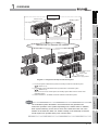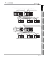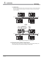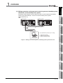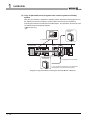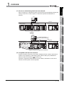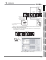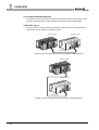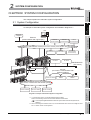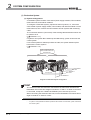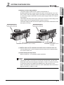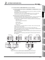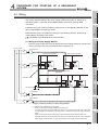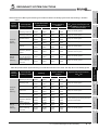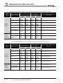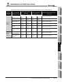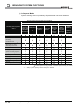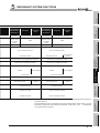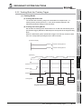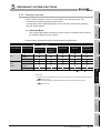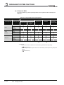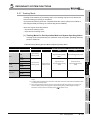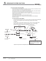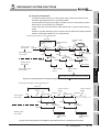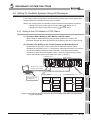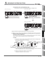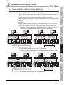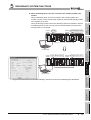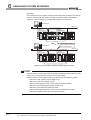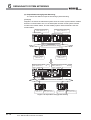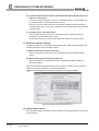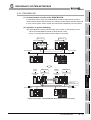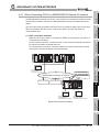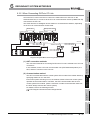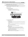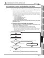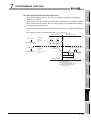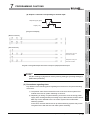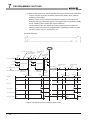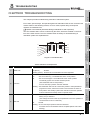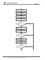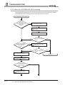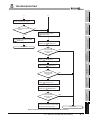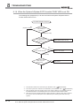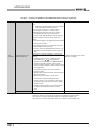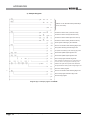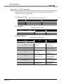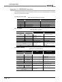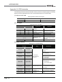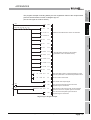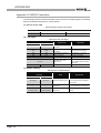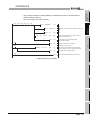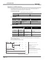
1
MITSUBISHI ELECTRIC
MELSEC System Q
Programmable Logic Controllers
Users's Manual
(Redundant System)
QnPRHCPU
(Q12PRHCPU/Q25PRHCPU)
Art. no.: 164264
10 04 2007
SH (NA)-080486
Version H
MITSUBISHI ELECTRIC
INDUSTRIAL AUTOMATION
SAFETY PRECAUTIONS
(Always read these instructions before using this equipment.)
Before using this product, please read this manual and the relevant manuals introduced in this manual
carefully and pay full attention to safety to handle the product correctly.
In this manual, the safety instructions are ranked as "DANGER" and "CAUTION".
DANGER
Indicates that incorrect handling may cause hazardous conditions,
resulting in death or severe injury.
CAUTION
Indicates that incorrect handling may cause hazardous conditions,
resulting in medium or slight personal injury or physical damage.
Note that the
CAUTION level may lead to a serious consequence according to the circumstances.
Always follow the instructions of both levels because they are important to personal safety.
Please save this manual to make it accessible when required and always forward it to the end user.
A-1
[Design Precautions]
DANGER
Install a safety circuit external to the PLC that keeps the entire system safe even when there are
problems with the external power supply or the PLC module. Otherwise, trouble could result from
erroneous output or erroneous operation.
(1) Outside the PLC, construct mechanical damage preventing interlock circuits such as emergency
stop, protective circuits, positioning upper and lower limits switches and interlocking forward/
reverse operations.
(2) When the PLC detects the following problems,
it will stop calculation and turn off all output in the case of (a).
In the case of (b), it will hold or turn off all output according to the parameter setting.
Q series module
(a) The power supply module has over current
protection equipment and over voltage
protection equipment.
Output OFF
(b) The CPU module self-diagnosis functions,
such as the watchdog timer error, detect
problems.
Hold or turn off all output according
to the parameter setting.
In addition, all output will be turned on when there are problems that the PLC CPU cannot
detect, such as in the I/O controller. Build a fail safe circuit exterior to the PLC that will make sure
the equipment operates safely at such times.
Refer to "LOADING AND INSTALLATION" in QCPU User's Manual (Hardware Design,
Maintenance and Inspection) for example fail safe circuits.
(3) Output could be left on or off when there is trouble in the outputs module relay or transistor. So
build an external monitoring circuit that will monitor any single outputs that could cause serious
trouble.
A-2
[Design Precautions]
DANGER
When overcurrent which exceeds the rating or caused by short-circuited load flows in the output
module for a long time, it may cause smoke or fire. To prevent this, configure an external safety
circuit, such as fuse.
Build a circuit that turns on the external power supply when the PLC main module power is turned
on.
If the external power supply is turned on first, it could result in erroneous output or erroneous
operation.
When there are communication problems with the data link, refer to the corresponding data link
manual for the operating status of each station.
Not doing so could result in erroneous output or erroneous operation.
When connecting a peripheral device to the CPU module or connecting a personal computer or the
like to the intelligent function module to exercise control (data change) on the running PLC, configure
up an interlock circuit in the sequence program to ensure that the whole system will always operate
safely.
Also before exercising other control (program change, operating status change (status control)) on
the running PLC, read the manual carefully and fully confirm safety.
Especially for the above control on the remote PLC from an external device, an immediate action
may not be taken for PLC trouble due to a data communication fault.
In addition to configuring up the interlock circuit in the sequence program, corrective and other
actions to be taken as a system for the occurrence of a data communication fault should be
predetermined between the external device and PLC CPU.
CAUTION
Do not bunch the control wires or communication cables with the main circuit or power wires, or
install them close to each other.
They should be installed 100 mm (3.94 inch) or more from each other.
Not doing so could result in noise that would cause erroneous operation.
When controlling items like lamp load, heater or solenoid valve using an output module, large current
(approximately ten times greater than that present in normal circumstances) may flow when the
output is turned OFF to ON.
Take measures such as replacing the module with one having sufficient rated current.
A-3
[Installation Precautions]
CAUTION
Use the PLC in an environment that meets the general specifications contained in QCPU User's
Manual (Hardware Design, Maintenance and Inspection).
Using this PLC in an environment outside the range of the general specifications could result in
electric shock, fire, erroneous operation, and damage to or deterioration of the product.
While pressing the installation lever located at the bottom of module, insert the module fixing tab into
the fixing hole in the base unit until it stops. Then, securely mount the module with the fixing hole as
a supporting point.
Incorrect loading of the module can cause a malfunction, failure or drop.
When using the PLC in the environment of much vibration, tighten the module with a screw.
Tighten the screw in the specified torque range.
Undertightening can cause a drop, short circuit or malfunction.
Overtightening can cause a drop, short circuit or malfunction due to damage to the screw or module.
When installing extension cables, be sure that the base unit and the extension module connectors
are installed correctly.
After installation, check them for looseness.
Poor connections could cause an input or output failure.
Securely load the memory card into the memory card loading connector.
After installation, check for lifting.
Poor connections could cause an operation fault.
Completely turn off the externally supplied power used in the system before mounting or removing
the module. Not doing so could result in damage to the product.Note that the module can be
changed online (while power is on) in the system that uses the Redundant CPU module or on the
MELSECNET/H remote I/O station.
Note that there are restrictions on the modules that can be changed online(while power is on), and
each module has its predetermined changing procedure.
For details, refer to Section 2.4.
Do not directly touch the module's conductive parts or electronic components.
Touching the conductive parts could cause an operation failure or give damage to the module.
A-4
[Wiring Precautions]
DANGER
Completely turn off the externally supplied power used in the system when installing or placing
wiring.
Not completely turning off all power could result in electric shock or damage to the product.
When turning on the power supply or operating the module after installation or wiring work, be sure
that the module's terminal covers are correctly attached.
Not attaching the terminal cover could result in electric shock.
DANGER
Be sure to ground the FG terminals and LG terminals to the protective ground conductor.
Not doing so could result in electric shock or erroneous operation.
When wiring in the PLC, be sure that it is done correctly by checking the product's rated voltage and
the terminal layout.
Connecting a power supply that is different from the rating or incorrectly wiring the product could
result in fire or damage.
External connections shall be crimped or pressure welded with the specified tools, or correctly
soldered.
Imperfect connections could result in short circuit, fires, or erroneous operation.
Tighten the terminal screws with the specified torque.
If the terminal screws are loose, it could result in short circuits, fire, or erroneous operation.
Tightening the terminal screws too far may cause damages to the screws and/or the module,
resulting in fallout, short circuits, or malfunction.
Be sure there are no foreign substances such as sawdust or wiring debris inside the module.
Such debris could cause fires, damage, or erroneous operation.
The module has an ingress prevention label on its top to prevent foreign matter, such as wire offcuts,
from entering the module during wiring.
Do not peel this label during wiring.
Before starting system operation, be sure to peel this label because of heat dissipation.
Install our PLC in a control panel for use. Wire the main power supply to the power supply module
installed in a control panel through a distribution terminal block. Furthermore, the wiring and
replacement of a power supply module have to be performed by a maintenance worker who
acquainted with shock protection. (QCPU User's Manual (Hardware Design, Maintenance and
Inspection)).
A-5
[Startup and Maintenance precautions]
DANGER
Do not touch the terminals while power is on.
Doing so could cause shock or erroneous operation.
Correctly connect the battery.
Also, do not charge, disassemble, heat, place in fire, short circuit, or solder the battery.
Mishandling of battery can cause overheating or cracks which could result in injury and fires.
Switch off all phases of the externally supplied power used in the system when cleaning the module
or retightening the terminal or module mounting screws.
Not doing so could result in electric shock.
Undertightening of terminal screws can cause a short circuit or malfunction.
Overtightening of screws can cause damages to the screws and/or the module, resulting in fallout,
short circuits, or malfunction.
A-6
[Startup and Maintenance precautions]
CAUTION
The online operations conducted for the CPU module being operated, connecting the peripheral
device (especially, when changing data or operation status), shall be conducted after the manual has
been carefully read and a sufficient check of safety has been conducted.
Operation mistakes could cause damage or problems with of the module.
Do not disassemble or modify the modules.
Doing so could cause trouble, erroneous operation, injury, or fire.
Use any radio communication device such as a cellular phone or a PHS phone more than 25cm
(9.85 inch) away in all directions of the PLC.
Not doing so can cause a malfunction.
Completely turn off the externally supplied power used in the system before mounting or removing
the module. Not doing so could result in damage to the product.
Note that the module can be changed online (while power is on) in the system that uses the
redundant CPU module or on the MELSECNET/H remote I/O station.
Note that there are restrictions on the modules that can be changed online (while power is on), and
each module has its predetermined changing procedure.
For details, refer to Section 2.4.
Do not mount/remove the module onto/from the base unit or terminal block more than 50 times
(IEC61131-2-compliant), after the first use of the product.Failure to do so may cause to malfunction.
Do not drop or give an impact to the battery mounted to the module.
Doing so may damage the battery, causing the battery fluid to leak inside the battery.
If the battery is dropped or given an impact, dispose of it without using.
Before touching the module, always touch grounded metal, etc. to discharge static electricity from
human body, etc.
Not doing so can cause the module to fail or malfunction.
A-7
[Disposal Precautions]
CAUTION
When disposing of this product, treat it as industrial waste.
[Transportation Precautions]
CAUTION
When transporting lithium batteries, make sure to treat them based on the transport regulations.
(Refer to QCPU User's Manual (Hardware Design, Maintenance and Inspection))
A-8
REVISIONS
Print Date
The manual number is given on the bottom left of the back cover.
Manual Number
Revision
Jun., 2004
SH(NA)-080486ENG-A First edition
Jun., 2005
SH(NA)-080486ENG-B Partial correction
GENERIC TERMS AND ABBREVIATIONS, Chapter 1, Section 2.3, 6.2.2, 8.1.1,
8.3.3, 9.1, 9.2
Aug., 2005
SH(NA)-080486ENG-C Partial correction
GENERIC TERMS AND ABBREVIATIONS, Section 2.1, 2.3, Chapter 4, Section
5.1.3, 5.1.4, 5.3.1, 5.4, 5.5.1, 5.5.3, 5.5.6, 5.5.7, 5.6.2, 5.7, 5.9, 6.2.1, 7.1, 8.3.3,
9.2, Appendix 1, Appendix 4
Mar., 2006
SH(NA)-080486ENG-D Partial correction
GENERIC TERMS AND ABBREVIATIONS, Section 2.1, 2.3, 4.2, 5.3.5, 6.2.2,
Appendix 4.3, Appendix 4.5
Jun., 2006
SH(NA)-080486ENG-E Addition function
QJ71PB92V
Addition
Section 6.2.6
Partial correction
ABOUT MANUALS, Section 1.2, 2.1, 2.3, 5.3.1, 5.3.4, 6.2, 7.1, 9.2
Jun., 2006
SH(NA)-080486ENG-F Addition function
Dec., 2006
SH(NA)-080486ENG-G Addition function
SAFETY PRECAUTIONS,Appendix 4.3, Section 2.3, 2.4, Appendix 4.5
SAFETY PRECAUTIONS, Section 4.2, 5.5.3, 7.1, 7.3, 8.2, Appendix 4.5,
Appendix 5
Apr., 2007
SH(NA)-080486ENG-H Revision involving Redundant CPU serial No.09012
Addition function
Q65WRB
Partial Addition
SAFETY PRECAUTIONS, Section 1.1, 1.2, 2.1, 2.3, 2.4, Chapter 4, Section 4.1,
4.2, 4.4, 5.1.3, 5.1.4, 5.1.5, 5.3.1, 5.2, 5.4, 5.5.1, 5.6.1, 5.8, 5.10.1, 5.10.2, 6.1.3,
6.2, 6.2.1, 6.2.2, 6.2.3, 6.2.4, 6.2.5, 6.3, 6.3.1, 6.3.2, 6.3.3, 6.3.4, 7.1, 7.2,
Chapter 8, Section 8.1.2, 8.1.4, 8.1.5, 8.3.4, 8.3.6, 9.2, Appendix 1, Appendix 2,
Appendix 3
Addition
Section 8.1.9, 8.1.10, 8.1.11, 8.3.8, 8.3.10, Chapter 6, Section 6.1, 6.2, 6.3, 6.4,
6.5, 6.6, 6.7, 6.8, 6.9, 6.10, Chapter 7
Chapter number correction
Section 8.3.8
8.3.9
Japanese Manual Version SH-080474-H
This manual confers no industrial property rights or any rights of any other kind, nor does it confer any patent licenses.
Mitsubishi Electric Corporation cannot be held responsible for any problems involving industrial property rights which may
occur as a result of using the contents noted in this manual.
C
2004 MITSUBISHI ELECTRIC CORPORATION
A-9
INTRODUCTION
Thank you for choosing the Mitsubishi MELSEC-Q Series of General Purpose Programmable Controllers.
Before using the equipment, please read this manual carefully to develop full familiarity with the functions
and performance of the Q series PLC you have purchased, so as to ensure correct use.
CONTENTS
SAFETY PRECAUTIONS •••••••••••••••••••••••••••••••••••••••••••••••••••••••••••••••••••••••••••••••••••••••••••••••••••••• A - 1
REVISIONS ••••••••••••••••••••••••••••••••••••••••••••••••••••••••••••••••••••••••••••••••••••••••••••••••••••••••••••••••••••••• A - 9
ABOUT MANUALS ••••••••••••••••••••••••••••••••••••••••••••••••••••••••••••••••••••••••••••••••••••••••••••••••••••••••••••• A - 14
HOW TO USE THIS MANUAL ••••••••••••••••••••••••••••••••••••••••••••••••••••••••••••••••••••••••••••••••••••••••••••••• A - 16
HOW THIS MANUAL IS ORGANIZED ••••••••••••••••••••••••••••••••••••••••••••••••••••••••••••••••••••••••••••••••••••• A - 17
GENERIC TERMS AND ABBREVIATIONS ••••••••••••••••••••••••••••••••••••••••••••••••••••••••••••••••••••••••••••••• A - 19
RELEVANT TERMS ••••••••••••••••••••••••••••••••••••••••••••••••••••••••••••••••••••••••••••••••••••••••••••••••••••••••••• A - 20
CHAPTER1 OVERVIEW
1 - 1 to 1 - 22
1.1
Redundant System Overview••••••••••••••••••••••••••••••••••••••••••••••••••••••••••••••••••••••••••••••••••• 1 - 10
1.2
Features •••••••••••••••••••••••••••••••••••••••••••••••••••••••••••••••••••••••••••••••••••••••••••••••••••••••••••• 1 - 12
CHAPTER2 SYSTEM CONFIGURATION
2 - 1 to 2 - 18
2.1
System Configuration ••••••••••••••••••••••••••••••••••••••••••••••••••••••••••••••••••••••••••••••••••••••••••••••2 - 1
2.2
Peripheral Device Configuration ••••••••••••••••••••••••••••••••••••••••••••••••••••••••••••••••••••••••••••••• 2 - 10
2.3
Applicable Devices and Software •••••••••••••••••••••••••••••••••••••••••••••••••••••••••••••••••••••••••••••• 2 - 11
2.4
System Configuration Cautions •••••••••••••••••••••••••••••••••••••••••••••••••••••••••••••••••••••••••••••••• 2 - 14
CHAPTER3 TRACKING CABLE
3 - 1 to 3 - 4
3.1
Specifications ••••••••••••••••••••••••••••••••••••••••••••••••••••••••••••••••••••••••••••••••••••••••••••••••••••••••3 - 1
3.2
Part Names ••••••••••••••••••••••••••••••••••••••••••••••••••••••••••••••••••••••••••••••••••••••••••••••••••••••••••3 - 1
3.3
Connecting and Disconnecting a Tracking Cable ••••••••••••••••••••••••••••••••••••••••••••••••••••••••••••3 - 2
CHAPTER4 PROCEDURE FOR STARTING UP A REDUNDANT SYSTEM
4 - 1 to 4 - 14
4.1
Mounting Modules ••••••••••••••••••••••••••••••••••••••••••••••••••••••••••••••••••••••••••••••••••••••••••••••••••4 - 4
4.2
Wiring •••••••••••••••••••••••••••••••••••••••••••••••••••••••••••••••••••••••••••••••••••••••••••••••••••••••••••••••••4 - 5
4.3
Module Initial Settings••••••••••••••••••••••••••••••••••••••••••••••••••••••••••••••••••••••••••••••••••••••••••••••4 - 9
4.4
Confirming that the Power Supply is ON •••••••••••••••••••••••••••••••••••••••••••••••••••••••••••••••••••••••4 - 9
4.5
Confirming System A/System B•••••••••••••••••••••••••••••••••••••••••••••••••••••••••••••••••••••••••••••••• 4 - 10
4.6
Starting up/Connecting GX Developer •••••••••••••••••••••••••••••••••••••••••••••••••••••••••••••••••••••••• 4 - 10
4.7
Writing Parameters and Programs to CPU •••••••••••••••••••••••••••••••••••••••••••••••••••••••••••••••••• 4 - 11
4.8
Restarting System A and System B ••••••••••••••••••••••••••••••••••••••••••••••••••••••••••••••••••••••••••• 4 - 12
A - 10
4.9
Error Check •••••••••••••••••••••••••••••••••••••••••••••••••••••••••••••••••••••••••••••••••••••••••••••••••••••••• 4 - 12
4.10 Confirming the Control System/Standby System ••••••••••••••••••••••••••••••••••••••••••••••••••••••••••• 4 - 13
4.11 Running CPU Modules •••••••••••••••••••••••••••••••••••••••••••••••••••••••••••••••••••••••••••••••••••••••••• 4 - 13
CHAPTER5 REDUNDANT SYSTEM FUNCTIONS
5.1
5 - 1 to 5 - 142
Basic Concept of Redundant System •••••••••••••••••••••••••••••••••••••••••••••••••••••••••••••••••••••••••••5 - 1
5.1.1
5.1.2
5.1.3
5.1.4
5.1.5
5.1.6
Determination of System A/System B •••••••••••••••••••••••••••••••••••••••••••••••••••••••••••••••••••••5 - 3
Determination of Control System and Standby System •••••••••••••••••••••••••••••••••••••••••••••••5 - 5
Operation Mode •••••••••••••••••••••••••••••••••••••••••••••••••••••••••••••••••••••••••••••••••••••••••••••••5 - 9
System Consistency Check ••••••••••••••••••••••••••••••••••••••••••••••••••••••••••••••••••••••••••••••• 5 - 15
Self Diagnostics Function•••••••••••••••••••••••••••••••••••••••••••••••••••••••••••••••••••••••••••••••••• 5 - 25
Start Mode •••••••••••••••••••••••••••••••••••••••••••••••••••••••••••••••••••••••••••••••••••••••••••••••••••• 5 - 28
5.2
FUNCTION LIST •••••••••••••••••••••••••••••••••••••••••••••••••••••••••••••••••••••••••••••••••••••••••••••••••• 5 - 31
5.3
The System Switching Function•••••••••••••••••••••••••••••••••••••••••••••••••••••••••••••••••••••••••••••••• 5 - 32
5.3.1
5.3.2
5.3.3
5.3.4
5.3.5
5.3.6
System Switching Method ••••••••••••••••••••••••••••••••••••••••••••••••••••••••••••••••••••••••••••••••• 5 - 32
System Switching Execution Timing••••••••••••••••••••••••••••••••••••••••••••••••••••••••••••••••••••• 5 - 42
System Switching Execution Possibility •••••••••••••••••••••••••••••••••••••••••••••••••••••••••••••••• 5 - 43
Both Systems Operations After System Switching ••••••••••••••••••••••••••••••••••••••••••••••••••• 5 - 50
Special Relays/Registers For System Switching•••••••••••••••••••••••••••••••••••••••••••••••••••••• 5 - 52
System Switching Precautions ••••••••••••••••••••••••••••••••••••••••••••••••••••••••••••••••••••••••••• 5 - 55
5.4
Operation Mode Change Function •••••••••••••••••••••••••••••••••••••••••••••••••••••••••••••••••••••••••••• 5 - 57
5.5
Tracking Function ••••••••••••••••••••••••••••••••••••••••••••••••••••••••••••••••••••••••••••••••••••••••••••••••• 5 - 74
5.5.1
5.5.2
5.5.3
5.5.4
5.5.5
5.5.6
5.5.7
5.5.8
5.6
Tracking Function Overview •••••••••••••••••••••••••••••••••••••••••••••••••••••••••••••••••••••••••••••• 5 - 74
Tracking Execution Procedure•••••••••••••••••••••••••••••••••••••••••••••••••••••••••••••••••••••••••••• 5 - 77
Tracking Data •••••••••••••••••••••••••••••••••••••••••••••••••••••••••••••••••••••••••••••••••••••••••••••••• 5 - 78
Tracking Data Settings ••••••••••••••••••••••••••••••••••••••••••••••••••••••••••••••••••••••••••••••••••••• 5 - 85
Tracking Block And Tracking Trigger•••••••••••••••••••••••••••••••••••••••••••••••••••••••••••••••••••• 5 - 87
Tracking Execution•••••••••••••••••••••••••••••••••••••••••••••••••••••••••••••••••••••••••••••••••••••••••• 5 - 91
Tracking Mode ••••••••••••••••••••••••••••••••••••••••••••••••••••••••••••••••••••••••••••••••••••••••••••••• 5 - 93
Device Data Used By The New Control System •••••••••••••••••••••••••••••••••••••••••••••••••••••• 5 - 98
Writing To The Both Systems Using GX Developer•••••••••••••••••••••••••••••••••••••••••••••••••••••••• 5 - 99
5.6.1
5.6.2
Writing to the CPU Module in STOP Status•••••••••••••••••••••••••••••••••••••••••••••••••••••••••••• 5 - 99
Program Change While CPU is Running ••••••••••••••••••••••••••••••••••••••••••••••••••••••••••••••5 - 102
5.7
Memory Copy From Control System To Standby System •••••••••••••••••••••••••••••••••••••••••••••••5 - 113
5.8
Online Module Change (Hot Swapping) •••••••••••••••••••••••••••••••••••••••••••••••••••••••••••••••••••••5 - 125
5.9
Network Module Redundant Group Settings •••••••••••••••••••••••••••••••••••••••••••••••••••••••••••••••5 - 127
5.10 Redundant CPU Functions Restricted in Redundant System•••••••••••••••••••••••••••••••••••••••••••5 - 129
5.10.1
5.10.2
Enforced ON/OFF of external I/O •••••••••••••••••••••••••••••••••••••••••••••••••••••••••••••••••••••••5 - 129
Remote Operation for Redundant System ••••••••••••••••••••••••••••••••••••••••••••••••••••••••••••5 - 133
5.11 Access to Module Mounted on Extension Base Unit••••••••••••••••••••••••••••••••••••••••••••••••••••••5 - 141
CHAPTER6 REDUNDANT SYSTEM NETWORKS
6.1
6 - 1 to 6 - 52
Communication with GX Developer and PX Developer •••••••••••••••••••••••••••••••••••••••••••••••••••••6 - 1
6.1.1
6.1.2
Communication Methods with GX Developer••••••••••••••••••••••••••••••••••••••••••••••••••••••••••••6 - 1
Confirming the Connection Target on GX Developer •••••••••••••••••••••••••••••••••••••••••••••••••6 - 3
A - 11
6.1.3
6.2
Redundant System Network Overview •••••••••••••••••••••••••••••••••••••••••••••••••••••••••••••••••••••••••6 - 7
6.2.1
6.2.2
6.2.3
6.2.4
6.2.5
6.2.6
6.3
Cautions on Access from GX Developer and PX Developer •••••••••••••••••••••••••••••••••••••••••6 - 4
MELSECNET/H PLC to PLC network •••••••••••••••••••••••••••••••••••••••••••••••••••••••••••••••••••••6 - 8
MELSECNET/H Remote I/O network ••••••••••••••••••••••••••••••••••••••••••••••••••••••••••••••••••• 6 - 15
Ethernet ••••••••••••••••••••••••••••••••••••••••••••••••••••••••••••••••••••••••••••••••••••••••••••••••••••••• 6 - 23
CC-Link•••••••••••••••••••••••••••••••••••••••••••••••••••••••••••••••••••••••••••••••••••••••••••••••••••••••• 6 - 27
Serial Communication Modules •••••••••••••••••••••••••••••••••••••••••••••••••••••••••••••••••••••••••• 6 - 34
PROFIBUS-DP •••••••••••••••••••••••••••••••••••••••••••••••••••••••••••••••••••••••••••••••••••••••••••••• 6 - 39
Communication between the Both Systems CPU Module and GOTs •••••••••••••••••••••••••••••••••• 6 - 41
6.3.1
6.3.2
6.3.3
6.3.4
When Connecting GOTs to a MELSECNET/H Remote I/O network •••••••••••••••••••••••••••••• 6 - 43
When Connecting GOTs to CC-Link •••••••••••••••••••••••••••••••••••••••••••••••••••••••••••••••••••• 6 - 45
Communication when the GOT is Connected to MELSECNET/H or
MELSECNET/10 PLC to PLC Network ••••••••••••••••••••••••••••••••••••••••••••••••••••••••••••••••• 6 - 46
When Connecting GOTs to a Ethernet•••••••••••••••••••••••••••••••••••••••••••••••••••••••••••••••••• 6 - 47
6.4
Precautions for Accessing Redundant CPU from Other Networks •••••••••••••••••••••••••••••••••••••• 6 - 49
6.5
Precautions for Writing Device Data from Other Station •••••••••••••••••••••••••••••••••••••••••••••••••• 6 - 51
CHAPTER7 PROGRAMMING CAUTIONS
7 - 1 to 7 - 22
7.1
Instructions Restricted in Use for Redundant System •••••••••••••••••••••••••••••••••••••••••••••••••••••••7 - 1
7.2
Cautions on Fixed-scan Clocks/Programs •••••••••••••••••••••••••••••••••••••••••••••••••••••••••••••••••••••7 - 9
7.3
Precautions for Using Annunciator (F) in Redundant System•••••••••••••••••••••••••••••••••••••••••••• 7 - 14
7.4
Precautions at System Switching Occurrence •••••••••••••••••••••••••••••••••••••••••••••••••••••••••••••• 7 - 16
7.5
Precautions of Programming when Connecting Extension Base Unit •••••••••••••••••••••••••••••••••• 7 - 22
CHAPTER8 TROUBLESHOOTING
8.1
8 - 1 to 8 - 48
Troubleshooting Flow ••••••••••••••••••••••••••••••••••••••••••••••••••••••••••••••••••••••••••••••••••••••••••••••8 - 3
8.1.1
8.1.2
8.1.3
8.1.4
8.1.5
8.1.6
8.1.7
8.1.8
8.1.9
8.1.10
8.1.11
8.1.12
Flow for the Case where the "MODE" LED is not ON••••••••••••••••••••••••••••••••••••••••••••••••••8 - 4
When the CPU Module "BACKUP" LED is ON (Red) ••••••••••••••••••••••••••••••••••••••••••••••••••8 - 5
When the "SYSTEM A/B" LED is flashing ••••••••••••••••••••••••••••••••••••••••••••••••••••••••••••••••8 - 8
When the System A/System B CPU module "RUN" LED is not ON••••••••••••••••••••••••••••••• 8 - 10
When System Switching has Occurred ••••••••••••••••••••••••••••••••••••••••••••••••••••••••••••••••• 8 - 12
When System Switching has failed •••••••••••••••••••••••••••••••••••••••••••••••••••••••••••••••••••••• 8 - 14
When "TRK. INIT. ERROR (error code: 6140)" Occurred at Redundant System Startup••••• 8 - 19
When "CONTROL SYS. DOWN (error code: 6310 to 6312)" Occurred at
Redundant System Startup•••••••••••••••••••••••••••••••••••••••••••••••••••••••••••••••••••••••••••••••• 8 - 20
When "ETX.CABLE ERR." Occurs •••••••••••••••••••••••••••••••••••••••••••••••••••••••••••••••••••••• 8 - 21
When "BASE LAY ERROR" Occurs ••••••••••••••••••••••••••••••••••••••••••••••••••••••••••••••••••••• 8 - 22
When "UNIT LAY DIFF." Occurs ••••••••••••••••••••••••••••••••••••••••••••••••••••••••••••••••••••••••• 8 - 24
When "CAN'T SWITCH" Occurs to Control System CPU Module due to
Communication Error when Turning ON/OFF Power Supply of CPU Module or
Booting and Shutting Down Personal Computer in MELSECNET/H Network System •••••••• 8 - 25
8.2
Error Clear•••••••••••••••••••••••••••••••••••••••••••••••••••••••••••••••••••••••••••••••••••••••••••••••••••••••••• 8 - 27
8.3
Replacing Module in Redundant System••••••••••••••••••••••••••••••••••••••••••••••••••••••••••••••••••••• 8 - 31
8.3.1
8.3.2
8.3.3
A - 12
CPU Module Replacement •••••••••••••••••••••••••••••••••••••••••••••••••••••••••••••••••••••••••••••••• 8 - 31
Power Supply Module Replacement Procedure••••••••••••••••••••••••••••••••••••••••••••••••••••••• 8 - 33
Redundant Power Supply Replacement Procedure •••••••••••••••••••••••••••••••••••••••••••••••••• 8 - 35
8.3.4
8.3.5
8.3.6
8.3.7
8.3.8
8.3.9
8.3.10
I/O Module Replacement Procedure •••••••••••••••••••••••••••••••••••••••••••••••••••••••••••••••••••• 8 - 36
Network Module Replacement Procedure•••••••••••••••••••••••••••••••••••••••••••••••••••••••••••••• 8 - 38
Main Base Unit Replacement Procedure ••••••••••••••••••••••••••••••••••••••••••••••••••••••••••••••• 8 - 40
Procedure for Replacing Module mounted on the I/O Station of Redundant System•••••••••• 8 - 43
Replacement of Modules Mounted to Extension Base Unit••••••••••••••••••••••••••••••••••••••••• 8 - 44
Tracking Cable Replacement ••••••••••••••••••••••••••••••••••••••••••••••••••••••••••••••••••••••••••••• 8 - 45
Replacement Procedures of Extension Cable ••••••••••••••••••••••••••••••••••••••••••••••••••••••••• 8 - 47
CHAPTER9 PROCESSING TIME FOR REDUNDANT SYSTEMS
9 - 1 to 9 - 8
9.1
Extension of Scan Time due to Tracking •••••••••••••••••••••••••••••••••••••••••••••••••••••••••••••••••••••••9 - 2
9.2
System Switching Time ••••••••••••••••••••••••••••••••••••••••••••••••••••••••••••••••••••••••••••••••••••••••••••9 - 6
APPENDICES
App - 1 to App - 51
Appendix 1 Comparison of Q4ARCPU and QnPRHCPU•••••••••••••••••••••••••••••••••••••••••••••••••••••••• App - 1
Appendix 2 Comparison of Qn(H)CPU and QnPRHCPU•••••••••••••••••••••••••••••••••••••••••••••••••••••••• App - 5
Appendix 3 Comparison of QnPHCPU and QnPRHCPU•••••••••••••••••••••••••••••••••••••••••••••••••••••••• App - 8
Appendix 4 Sample Programs when Using CC-Link ••••••••••••••••••••••••••••••••••••••••••••••••••••••••••••App - 11
Appendix 4.1
Sample Program System Configuration ••••••••••••••••••••••••••••••••••••••••••••••••••••App - 11
Appendix 4.2
Sample Program Names•••••••••••••••••••••••••••••••••••••••••••••••••••••••••••••••••••••••App - 11
Appendix 4.3
Devices Used in Programs ••••••••••••••••••••••••••••••••••••••••••••••••••••••••••••••••••••App - 12
Appendix 4.4
Parameter Settings •••••••••••••••••••••••••••••••••••••••••••••••••••••••••••••••••••••••••••••App - 14
Appendix 4.5
Sample Program ••••••••••••••••••••••••••••••••••••••••••••••••••••••••••••••••••••••••••••••••App - 18
Appendix 5 Method for Starting up the Previous Control System•••••••••••••••••••••••••••••••••••••••••••••App - 24
Appendix 6 Precautions for Using Serial Communication Module ••••••••••••••••••••••••••••••••••••••••••••App - 28
Appendix 6.1
CSET Instruction ••••••••••••••••••••••••••••••••••••••••••••••••••••••••••••••••••••••••••••••••App - 29
Appendix 6.2
UINI Instruction ••••••••••••••••••••••••••••••••••••••••••••••••••••••••••••••••••••••••••••••••••App - 34
Appendix 6.3
INPUT Instruction •••••••••••••••••••••••••••••••••••••••••••••••••••••••••••••••••••••••••••••••App - 37
Appendix 6.4
PUTE Instruction ••••••••••••••••••••••••••••••••••••••••••••••••••••••••••••••••••••••••••••••••App - 38
Appendix 6.5
GETE Instruction ••••••••••••••••••••••••••••••••••••••••••••••••••••••••••••••••••••••••••••••••App - 40
Appendix 6.6
ONDEMAND Instruction •••••••••••••••••••••••••••••••••••••••••••••••••••••••••••••••••••••••App - 42
Appendix 6.7
OUTPUT Instruction ••••••••••••••••••••••••••••••••••••••••••••••••••••••••••••••••••••••••••••App - 44
Appendix 6.8
PRR Instruction ••••••••••••••••••••••••••••••••••••••••••••••••••••••••••••••••••••••••••••••••••App - 46
Appendix 6.9
BIDOUT Instruction •••••••••••••••••••••••••••••••••••••••••••••••••••••••••••••••••••••••••••••App - 48
Appendix 6.10 BIDIN Instruction ••••••••••••••••••••••••••••••••••••••••••••••••••••••••••••••••••••••••••••••••App - 50
Appendix 7 Restrictions on Communication via Module Mounted to Extension Base Unit ••••••••••••••App - 51
INDEX
INDEX - 1 to INDEX - 3
A - 13
ABOUT MANUALS
The following manuals are also related to this product.
In necessary, order them by quoting the details in the tables below.
Related Manuals
Manual Number
Manual Name
(Model Code)
QCPU User's Manual (Hardware Design, Maintenance and Inspection)
This manual provides the specifications of the CPU modules, power supply modules, base units, extension
SH-080483ENG
(13JR73)
cables, memory cards and others.
(Sold separately)
QCPU User's Manual (Function Explanation, Program Fundamentals)
This manual explains the functions, programming methods, devices necessary to create programs with the
SH-080484ENG
(13JR74)
QCPU.
(Sold separately)
QCPU (Q Mode)/QnACPU Programming Manual (Common Instructions)
This manual describes how to use the sequence instructions and application instructions.
(Sold separately)
QCPU (Q Mode)/QnACPU Programming Manual (PID Control Instructions)
This manual describes the dedicated instructions used to exercise PID control.
(Sold separately)
SH-080039
(13JF58)
SH-080040
(13JF59)
QCPU (Q Mode) Programming Manual (SFC)
This manual explains the system configuration, performance specifications, functions, programming, debugging,
SH-080041
(13JF60)
error codes and others of MELSAP3.
(Sold separately)
QCPU (Q Mode)/QnACPU Programming Manual (MELSAP-L)
This manual describes the programming methods, specifications functions, and so on that are necessary to
SH-080076
(13JF61)
create the MELSAP-L type SFC program.
(Sold separately)
QnPHCPU/QnPRHCPU Programming Manual (Process Control Instructions)
This manual describes the programming procedures, device names, and other items necessary to implement
SH-080316E
(13JF67)
PID control using process control instructions.
(Sold separately)
QCPU (Q Mode) Programming Manual (Structured Text)
SH-080366
This manual describes the structured text language programming methods.
(Sold separately)
(13JF68)
Q corresponding MELSECNET/H Network System Reference Manual (Remote I/O network)
This manual describes the system configuration, performance, specifications and programming of
SH-080124
(13JF96)
MELSECNET/H network system (Remote I/O nework).
(Sold separately)
Type MELSECNET/10 Network system (PLC to PLC network) Reference Manual
This manual describes the system configuration, performance, specifications and programming of
IB-66440
MELSECNET/10 network system (PLC to PLC network).
(13JE33)
(Sold separately)
A - 14
Related Manuals
Manual Number
Manual Name
(Model Code)
Q Corresponding Serial Communication Module User's Manual (Basic)
This manual provides an overview of the module and describes the applicable system configuration, the
specifications, the procedures prior to operations, the basic methods of communicating with the external device,
maintenance and inspection, and the troubleshooting of the Q-Corresponding Serial Communication Module.
SH-080006
(13JL86)
(Sold separately)
Q Corresponding Serial Communication Module User's Manual (Application)
This manual contains information on how to perform data communication with external devices using the
SH-080007
(13JL87)
module's special functions.
(Sold separately)
Q Corresponding Ethernet Interface Module User's Manual (Basic)
This manual contains information on the specifications of the Ethernet module, the procedures for data
communications with external devices, circuit connection (open/close), fixed buffer exchange, random access
buffer exchange, and the troubleshooting.
SH-080009
(13JL88)
(Sold separately)
Q Corresponding Ethernet Interface Module User's Manual (Application)
This manual explains the e-mail function of the Ethernet module, the PLC CPU status monitoring function, the
communication function via MELSECNET/H, MELSECNET/10 as well as the communication function using data
link instructions, and how to use file transfer (FTP server), etc.
SH-080010
(13JL89)
(Sold separately)
Q Corresponding MELSEC Communication Protocol Reference Manual
This manual explains the communication methods and control procedures through the MC protocol for the
external devices to read and write data from/to the CPU module using the serial communication module/
Ethernet module.
SH-080008
(13JF89)
(Sold separately)
CC-Link System Master/Local Module type QJ61BT11N User's Manual
This manual describes the system configuration, performance specification, function, handling, wiring and
SH-080394
(13JR64)
troubleshooting for QJ61BT11N.
(Sold separately)
PROFIBUS-DP Master Module User's Manual
This manual describes the system configuration, performance specification, function, handling, wiring and
SH-080572ENG
(13JR84)
troubleshooting for QJ71PB92V.
(Sold separately)
A - 15
HOW TO USE THIS MANUAL
This manual explains the redundant system configuration, functions, communication with external devices and troubleshooting.
The manual is classified roughly into three sections as shown below.
1) Chapter 1 and 2
Explains the redundant system overview and system
configuration
2) Chapter 3
Explains the tracking cable specifications, part names and
connection method.
3) Chapter 4
Explains starting up the redundant system.
4) Chapter 5
Explains the redundant system functions.
5) Chapter 6
Explains the communication between a redundant system
and each network, GOT and GX Developer.
6) Chapter 7
Explains the precautions for programming in a redundant
system.
7) Chapter 8
Explains the troubleshooting methods
replacement in a redundant system.
8) Chapter 9
Explains the processing time of a redundant system.
and
module
Remark
This manual does not explain the functions of power supply modules, base units,
extension cables, memory cards and batteries of CPU module.
For these details, refer to the manual shown below.
QCPU User's Manual (Hardware Design, Maintenance and Inspection)
This manual does not explain the functions of the CPU module.
For these functions, refer to the manual shown below.
QCPU User's Manual (Function Explanation, program Fundamentals)
A - 16
HOW THIS MANUAL IS ORGANIZED
Reference destination
A reference destination or
reference manual is marked
.
Chapter heading
The index on the right side of the page
shows the chapter of the open page at a
glance.
Section title
The section of the open page is shown at a
glance.
A - 17
In addition, this manual provides the following explanations.
POINT
Explains the matters to be especially noted, the functions and others related to the
description on that page.
Remark
Provides the reference destination related to the description on that page and the
convenient information.
A - 18
GENERIC TERMS AND ABBREVIATIONS
Unless otherwise specified, this manual uses the following generic terms
and abbreviations to explain the Redundant CPU.
Generic Term/Abbreviation
Description
Basic model QCPU
Generic term for Q00JCPU, Q00CPU and Q01CPU modules.
High Performance model QCPU
Generic term for Q02CPU, Q02HCPU, Q06HCPU Q12HCPU and Q25HCPU modules.
Process CPU
Generic term for Q12PHCPU and Q25PHCPU.
Redundant CPU
Generic term for Q12PRHCPU and Q25PRHCPU.
QCPU
Generic term for QnCPU QnHCPU QnPHCPU and QnPRHCPU.
QnCPU
Generic term for Q02HCPU.
QnHCPU
Generic term for Q02HCPU, Q06HCPU, Q12HCPU and Q25HCPU.
QnPHCPU
Generic term for Q12PHCPU and Q25PHCPU.
QnPRHCPU
Generic term for Q12PRHCPU and Q25PRHCPU.
Q Series
Abbreviation for Mitsubishi MELSEC-Q Series Programmable Logic Controller.
Product name for Q series compatible SW D5C-GPPW-E type GPP function software
package.
GX Developer
indicates the version.
For the GX Developer versions applicable for each CPU module, refer to "SYSTEM
CONFIGURATION" in this manual.
OPS
Abbreviation for the operation system that includes MELSOFT and EZSocket partner
products.
Generic term for Q33B, Q35B, Q38B and Q312B main base units on which CPU module
Q3 B
(except Q00JCPU), Q series power supply module, I/O module and intelligent function
module can be mounted.
Generic term for Q38RB redundant power supply base unit on which CPU module
Q3 RB
(except Q00JCPU), redundant power supply module, Q series I/O module and
intelligent function module can be mounted.
Q5 B
Generic term for Q52B and Q55B extension base unit on which the Q Series I/O and
intelligent function module can be mounted.
Generic term for Q63B, Q65B, Q68B, and Q612B extension base unit on which Q series
Q6 B
power supply module, Q series I/O module, and intelligent function module are
mounted.
Q6 RB
Other name for Q68RB redundant power supply base unit on which redundant power
supply module, Q series I/O module, and intelligent function module are mounted.
Other name for Q65WRB extension base unit for redundant system on which redundant
Q6 WRB
power supply module, Q series I/O module, and intelligent function module are
mounted.
Main base unit
Generic term for Q3 B and Q3 RB.
Extension base unit
Generic term for Q5 B, Q6 B, Q6 RB and Q6 WRB.
Slim type main base unit
Generic term for Q3 SB.
Redundant power main base unit
Generic term for Q3 RB.
Redundant power extension base
unit
Redundant type extension base
unit
Other name for Q6 RB.
Other name for Q6 WRB.
Generic term for main base unit, extension base unit, slim type main base unit,
Base unit
redundant power main base unit, redundant power extension base unit, and redundant
type extension base unit
A - 19
Generic Term/Abbreviation
Redundant base unit
Description
Generic term for redundant power main base unit, redundant power extension base unit,
and redundant type extension base unit.
Extension cable
Generic term for QC05B, QC06B, QC12B, QC30B, QC50B, QC100B extension cables.
Tracking cable
Generic term for QC10TR and QC30TR tracking cables for Redundant CPU.
Q series power supply module
Generic term for Q61P-A1, Q61P-A2, Q61P, Q62P, Q63P and Q64P power supply
modules.
Slim type power supply module
Generic term for Q61SP slim type power supply module.
Redundant power supply module
Generic term for Q63RP and Q64RP redundant power supply module.
Power supply module
Generic term for Q series power supply modules, AnS series power supply modules,
slim type power supply module and redundant power supply module.
Generic term for Q6BAT, Q7BAT and Q8BAT CPU module batteries Q2MEM-BAT
Battery
SRAM card battery.
SRAM card
Abbreviation for Q2MEM-1MBS and Q2MEM-2MBS type SRAM card.
Flash card
Generic term for Q2MEM-2MBF and Q2MEM-4MBF type Flash card.
ATA card
Generic term for Q2MEM-8MBA, Q2MEM-16MBA and Q2MEM-32MBA type ATA card.
Memory card
Generic term for SRAM card, Flash card and ATA card.
RELEVANT TERMS
Relevant Terms
Description
System A
The system to which the system A connector of tracking cable is connected.
System B
The system to which the system B connector of tracking cable is connected.
Host system
The system where the currently mentioned Redundant CPU module is mounted.
The system connected to the host system via the tracking cable.
Other system
If system A is the host system, system B is the other system; if system B is the host
system, system A is the other system.
Control system
Standby system
New control system
New standby system
The basic system that is controlling the redundant system and performing network
communication.
The basic system for backup that consists of the redundant system.
The system that has switched to control system from standby system after system
switching.
The system that has switched to standby system from control system after system
switching.
The slot that is located on the right side of the power supply module mounted on the
CPU slot
main base unit.
In the case of redundant power supply base unit, it indicates the slot that is located on
the right side of a pair of power supply modules.
A - 20
1
OVERVIEW
1
(1) Specifications and handling of QCPUs, Power Supply Modules, Base
Units, memory Cards, etc.
QCPU User's Manual (Hardware Design, Maintenance and Inspection)
2
SYSTEM
CONFIGURATION
This manual explains the redundant system configuration that includes redundant CPUs
and relevant functions, etc.
Please refer to the following manuals, for common specifications, performance, functions,
and others to QCPUs.
OVERVIEW
CHAPTER1 OVERVIEW
3
(2) Common Functions, Programs and Devices for QCPUs
TRACKING CABLE
QCPU User's Manual (Function Explanation, Program Fundamentals)
PROCEDURE FOR
STARTING UP A
REDUNDANT SYSTEM
4
REDUNDANT SYSTEM
FUNCTIONS
5
REDUNDANT SYSTEM
NETWORKS
6
PROGRAMMING
CAUTIONS
7
1-1
TROUBLESHOOTING
8
1
OVERVIEW
(3) List of Q Series CPU Module manuals
The Q series CPU module manuals are as shown below.
For details such as manual numbers, refer to "ABOUT MANUALS" in this manual.
(a) Basic model QCPU
Table1.1 List of user's manuals of basic model QCPU
Hardware
Maintenance
and
Inspection
Program
Fundamentals
Multi CPU
System
Redundant
system
(Included in package)
Purpose
QCPU (Q mode)
CPU Module User's
Manual (Hardware)
QCPU User's
Manual (Hardware
Design,
Maintenance and
inspection)
QCPU User's
Manual (Function
Explanation,
Program
Fundamentals)
QCPU User's
Manual (Multiple
CPU System)
Confirmation of part names and
specifications of the CPU module
Details
Outline
Outline
Confirmation of connection methods
for the power supply module, base
unit and I/O module
Details
Outline
Construction of the single CPU
system (confirmation of start-up
procedure and I/O number
Details
assignment)
Construction of the multiple CPU
system (confirmation of start-up
Details
procedure and I/O number
assignment)
Confirmation of the sequence program
Details
configuration and memory
Confirmation of the functions,
parameters, and devices of the CPU
Details
module
Confirmation of the troubleshooting
and error codes
1-2
Details
QnPRHCPU User's
Manual (Redundant
System)
1
OVERVIEW
1
QnPHCPU/
QnPRHCPU
Programming
Manual (Process
Control
Instruction)
SFC
MELSAP-L
Structured
Text
2
QCPU (Q mode)/
QnACPU
Programming
Manual (SFC)
QCPU (Q mode)
Programming
Manual
(MELSAP-L)
QCPU (Q mode)
Programming
Manual
(Structured Text)
Confirmation of usage of
3
sequence instructions, basic
instructions, application
Details
TRACKING CABLE
instructions, etc.
Confirmation of dedicated
instructions for PID control
Details
Confirmation of MELSAP3's
4
PROCEDURE FOR
STARTING UP A
REDUNDANT SYSTEM
system configuration,
performance specifications,
Details
functions, programming,
debugging, and error codes
Confirmation of the
programming method,
specifications, functions, etc.
Details
required for SFC programming
5
of the MELSAP-L type
Confirmation of the
programming method of the
SYSTEM
CONFIGURATION
QCPU (Q mode)/
QnACPU
Programming
Manual (PID
Control
Instruction)
Process
control
Instruction
Details
structured text language
REDUNDANT SYSTEM
FUNCTIONS
Purpose
QCPU (Q mode)/
QnACPU
Programming
Manual
(Common
Instruction)
PID control
Instructions
REDUNDANT SYSTEM
NETWORKS
6
PROGRAMMING
CAUTIONS
7
8
1-3
TROUBLESHOOTING
Common
Instructions
OVERVIEW
Table1.2 List of programming manuals of basic model QCPU
1
OVERVIEW
(b) High Performance Model QCPU
Table1.3 List of user's manuals of high performance model QCPU
Hardware
Maintenance
and
Inspection
Program
Fundamentals
Multi CPU
System
Redundant
system
(Included in package)
Purpose
QCPU (Q mode)
CPU Module User's
Manual (Hardware)
QCPU User's
Manual (Hardware
Design,
Maintenance and
inspection)
QCPU User's
Manual (Function
Explanation,
Program
Fundamentals)
QCPU User's
Manual (Multiple
CPU System)
Confirmation of part names and
specifications of the CPU module
Details
Outline
Outline
Confirmation of connection methods
for power supply module, base unit
and I/O module
Details
Outline
Construction of the single CPU
system (confirmation of start-up
procedure and I/O number
Details
assignment)
Construction of the multiple CPU
system (confirmation of start-up
Details
procedure and I/O number
assignment)
Confirmation of the sequence program
Details
configuration and memory
Confirmation of the functions,
parameters, and devices of CPU
Details
module
Confirmation of the troubleshooting
and error codes
1-4
Details
QnPRHCPU User's
Manual (Redundant
System)
1
OVERVIEW
1
QnPHCPU/
QnPRHCPU
Programming
Manual (Process
Control
Instruction)
SFC
MELSAP-L
Structured
Text
2
QCPU (Q mode)/
QnACPU
Programming
Manual (SFC)
QCPU (Q mode)
Programming
Manual
(MELSAP-L)
QCPU (Q mode)
Programming
Manual
(Structured Text)
Confirmation of usage of
3
sequence instructions, basic
instructions, application
Details
TRACKING CABLE
instructions, etc.
Confirmation of dedicated
instructions for PID control
Details
Confirmation of MELSAP3's
4
PROCEDURE FOR
STARTING UP A
REDUNDANT SYSTEM
system configuration,
performance specifications,
Details
functions, programming,
debugging, and error codes
Confirmation of the
programming method,
specifications, functions, etc.
Details
required for SFC programming
5
of the MELSAP-L type
Confirmation of the
programming method of the
SYSTEM
CONFIGURATION
QCPU (Q mode)/
QnACPU
Programming
Manual (PID
Control
Instruction)
Process
control
Instruction
Details
structured text language
REDUNDANT SYSTEM
FUNCTIONS
Purpose
QCPU (Q mode)/
QnACPU
Programming
Manual
(Common
Instruction)
PID control
Instructions
REDUNDANT SYSTEM
NETWORKS
6
PROGRAMMING
CAUTIONS
7
8
1-5
TROUBLESHOOTING
Common
Instructions
OVERVIEW
Table1.4 List of programming manuals of high performance model QCPU
1
OVERVIEW
(c) Process CPU
Table1.5 List of user's manuals of process CPU
Hardware
Maintenance
and
Inspection
Program
Fundamentals
Multi CPU
System
Redundant
system
(Included in package)
Purpose
QCPU (Q mode)
CPU Module User's
Manual (Hardware)
QCPU User's
Manual (Hardware
Design,
Maintenance and
inspection)
QCPU User's
Manual (Function
Explanation,
Program
Fundamentals)
QCPU User's
Manual (Multiple
CPU System)
Confirmation of part names and
specifications of the CPU module
Details
Outline
Outline
Confirmation of connection methods
for power supply module, base unit
and I/O module
Details
Outline
Construction of the single CPU
system (confirmation of start-up
procedure and I/O number
Details
assignment)
Construction of the multiple CPU
system (confirmation of start-up
Details
procedure and I/O number
assignment)
Confirmation of sequence program
Details
configuration and memory
Confirmation of the functions,
parameters, and devices of the CPU
Details
module
Confirmation of the troubleshooting
and error codes
1-6
Details
QnPRHCPU User's
Manual (Redundant
System)
1
OVERVIEW
1
QnPHCPU/
QnPRHCPU
Programming
Manual (Process
Control
Instruction)
SFC
MELSAP-L
Structured
Text
2
QCPU (Q mode)/
QnACPU
Programming
Manual (SFC)
QCPU (Q mode)
Programming
Manual
(MELSAP-L)
QCPU (Q mode)
Programming
Manual
(Structured Text)
Confirmation of usage of
3
sequence instructions, basic
instructions, application
Details
TRACKING CABLE
instructions, etc.
Confirmation of dedicated
instructions for process control
Details
Confirmation of MELSAP3's
4
PROCEDURE FOR
STARTING UP A
REDUNDANT SYSTEM
system configuration,
performance specifications,
Details
functions, programming,
debugging and error codes
Confirmation of the
programming method,
specifications, functions etc.
Details
required for SFC programming
5
of the MELSAP-L type
Confirmation of the
programming method of the
SYSTEM
CONFIGURATION
QCPU (Q mode)/
QnACPU
Programming
Manual (PID
Control
Instruction)
Process
control
Instruction
Details
structured text language
REDUNDANT SYSTEM
FUNCTIONS
Purpose
QCPU (Q mode)/
QnACPU
Programming
Manual
(Common
Instruction)
PID control
Instructions
REDUNDANT SYSTEM
NETWORKS
6
PROGRAMMING
CAUTIONS
7
8
1-7
TROUBLESHOOTING
Common
Instructions
OVERVIEW
Table1.6 List of programming manuals of process CPU
1
OVERVIEW
(d) Redundant CPU
Table1.7 List of user's manual of redundant CPU
Hardware
Maintenance
and
Inspection
Program
Fundamentals
Multi CPU
System
Redundant
system
(Included in package)
Purpose
QCPU (Q mode)
CPU Module User's
Manual (Hardware)
QCPU User's
Manual (Hardware
Design,
Maintenance and
inspection)
QCPU User's
Manual (Function
Explanation,
Program
Fundamentals)
QCPU User's
Manual (Multiple
CPU System)
QnPRHCPU User's
Manual (Redundant
System)
Confirmation of part names and
specifications of the CPU module
Details
Outline
Outline
Confirmation of connection methods
for power supply module, base unit
and I/O module
Details
Outline
Construction of redundant system
(confirmation of start-up procedure
Details
and I/O number assignment)
Confirmation of the configuration and
Details
memory of sequence programs
Confirmation of the functions,
parameters, devices, etc. of the CPU
Details
module
Confirmation of the troubleshooting
Confirmation of the error codes
1-8
Details
Details
1
OVERVIEW
1
QCPU (Q mode)/
QnACPU
Programming
Manual (PID
Control
Instruction)
Process
control
Instruction
QnPHCPU/
QnPRHCPU
Programming
Manual (Process
Control
Instruction)
SFC
MELSAP-L
Structured
Text
2
QCPU (Q mode)/
QnACPU
Programming
Manual (SFC)
QCPU (Q mode)
Programming
Manual
(MELSAP-L)
QCPU (Q mode)
Programming
Manual
(Structured Text
Edition)
Confirmation of usage of
3
sequence instructions, basic
instructions, application
Details
TRACKING CABLE
instructions, etc.
Confirmation of dedicated
instructions for PID control
Details
4
Confirmation of dedicated
Details
PROCEDURE FOR
STARTING UP A
REDUNDANT SYSTEM
instructions for process control
Confirmation of MELSAP3's
system configuration,
performance specifications,
Details
functions, programming,
debugging and error codes
5
REDUNDANT SYSTEM
FUNCTIONS
Confirmation of the
programming method,
specifications, functions, etc.
Details
required for SFC programming
of the MELSAP-L type
Confirmation of the
programming method of the
SYSTEM
CONFIGURATION
Purpose
QCPU (Q mode)/
QnACPU
Programming
Manual
(Common
Instruction)
PID control
Instructions
Details
6
REDUNDANT SYSTEM
NETWORKS
structured text language
PROGRAMMING
CAUTIONS
7
8
1-9
TROUBLESHOOTING
Common
Instructions
OVERVIEW
Table1.8 List of programming manuals of redundant CPU
1
OVERVIEW
1.1 Redundant System Overview
A redundant system offers improved system reliability, as it consists of two basic systems,
each of which includes the CPU module, power supply module, network module *3 and
others, so that even if a module error occurs in one basic system, the other one continues
the system control.
To configure a redundant system, prepare two sets of systems, i.e., two redundant main
base units on which the abovementioned modules are mounted. Then, connect the CPU
modules of both systems with a tracking cable.
Mount the I/O module and intelligent function module of the redundant system to the
MELSECNET/H remote I/O station or extension base unit.
In addition, the power supply module can be duplicated when using the redundant base
unit.
1 - 10
1.1 Redundant System Overview
OVERVIEW
1
Network module
CPU module
OVERVIEW
Redundant system
Standby system *2
Control system *1
Power supply module
Q35B
SYSTEM
CONFIGURATION
2
Q35B
Tracking cable
TRACKING CABLE
3
MELSECNET/H Remote I/O network
Redundantly powered
Remote I/O station
Q35B
PROCEDURE FOR
STARTING UP A
REDUNDANT SYSTEM
Q35B
4
Q38RB
Intelligent function
module
Output module
Input module
Q68RB
Redundant Power supply module
Diagram 1.1 Configuration Example of Redundant System
6
REDUNDANT SYSTEM
NETWORKS
* 1: The control system indicates the system that actually controls the redundant system.
(
Section 5.1.2)
* 2: The standby system indicates the backup system within a redundant system.
(
Section 5.1.2)
If an error occurs in the control system, the standby system takes over the control of the
redundant system.
* 3: Refer to Section 2.3, for details of network modules for redundant system.
7
Remark
The redundant system described in this manual does not guarantee the
continuous operation of the system depending on the failure status. In addition,
when system switching occurs due to errors of the extension base unit or the
module on the extension base unit. Create a safety circuit externally so that the
overall system can operate safely even in these cases.
1.1 Redundant System Overview
1 - 11
PROGRAMMING
CAUTIONS
Q65B
REDUNDANT SYSTEM
FUNCTIONS
5
8
TROUBLESHOOTING
1
1
OVERVIEW
1.2 Features
Features of redundant system are indicated below.
(1) Redundant Configuration of Basic System
As a redundant system consists two basic systems, i.e., two sets of CPU modules,
power supply modules, main base units, network module*3, etc., one of the basic
systems controls the whole system, while the other one performs backup.
Data of the CPU module performing control is transmitted to the backup CPU module
in order to make the data consistent. This enables the backup system to take over the
redundant system control after the control system goes down and system switching
occurs.
Control system *1
Network module
CPU module
Power supply
module
Standby system *2
Data tracking
Control system
Tracking cable
Continue control using
device data from
control system
Malfunction!
Tracking cable
Diagram 1.2 Redundant Configuration of Basic System
* 1: The control system indicates the system that actually controls the a redundant system.
(
Section 5.1.2)
* 2: The standby system indicates the backup system within a redundant system.
(
Section 5.1.2)
If an error occurs in the control system, the standby system takes over the control of the
redundant system.
* 3: Refer to Section 2.3, for details of network modules compatible for redundant system.
1 - 12
1.2 Features
OVERVIEW
1
Control system
Standby system
3
TRACKING CABLE
Tracking cable
Extension cable
Q65WRB
IN1
IN2
2
SYSTEM
CONFIGURATION
In the redundant system where the Redundant CPU whose first 5 digits of serial No. is
"09012" or later is used in both systems, the extension base unit can be connected.
Since communication can be made not by network but via bus, communication with
the I/O module and the intelligent function module can be made in high speed.
OVERVIEW
(2) Connection of Extension Base Unit
OUT
PROCEDURE FOR
STARTING UP A
REDUNDANT SYSTEM
4
For the precautions of the system configuration when connecting the extension base unit, refer to
Section 2.4.
Diagram 1.3 System Configuration when Connecting Extension Base Unit
5
REDUNDANT SYSTEM
NETWORKS
6
7
PROGRAMMING
CAUTIONS
*:
REDUNDANT SYSTEM
FUNCTIONS
Q68RB
8
1.2 Features
1 - 13
TROUBLESHOOTING
1
1
OVERVIEW
(3) Network Configuration Including Redundant System.
(a) MELSECNET/H PLC to PLC Network and Ethernet
In the case of MELSECNET/H PLC to PLC network and Ethernet, control/standby
system switching occurs and system control and network communication is
continued even when a network module fails or when network cable
disconnection is detected.
(Control station)
(Normal station)
OPS (Normal station)
MELSECNET/H
Interface Board
MELSECNET/H PLC to PLC network
Control system
(Normal station)
Standby system
(Normal station)
Tracking cable
(Control station)
(Normal station)
OPS (Normal station)
MELSECNET/H
Interface Board
MELSECNET/H PLC to PLC network
Standby system
Control system
(Normal station)
Communication not
possible (malfunction,
severed network cable)
Tracking cable
Control and network
automatic system
switching
Diagram 1.4 System Configuration for MELSECNET/H PLC to PLC Network
1 - 14
1.2 Features
OVERVIEW
(b) MELSECNET/H Remote I/O Network
MELSECNET/H remote I/O stations can continue the operation even when
control/standby system switching occurs. (
Multiplexed Remote Master Station
Multiplexed Remote Sub-master Station
2
Standby system
SYSTEM
CONFIGURATION
Control system
Section 6.2.2)
Tracking cable
MELSECNET/H Remote I/O network
Remote I/O
station
3
Remote I/O
station
TRACKING CABLE
Remote I/O
station
OVERVIEW
1
Multiplexed Remote Sub-master Station (Master Station operation)
Control system
Error, fault
PROCEDURE FOR
STARTING UP A
REDUNDANT SYSTEM
4
5
REDUNDANT SYSTEM
FUNCTIONS
Tracking cable
MELSECNET/H Remote I/O network
Remote I/O
station
Remote I/O
station
Remote I/O
station
REDUNDANT SYSTEM
NETWORKS
6
Diagram 1.5 System Configuration for MELSECNET/H Remote I/O Network
PROGRAMMING
CAUTIONS
7
8
1.2 Features
1 - 15
TROUBLESHOOTING
1
1
OVERVIEW
(c) PROFIBUS-DP
When the PROFIBUS-DP master module detects a fault or communication failure
with slave stations, the both systems are switched so that the communications
can be continued.
Control system
Standby system
Tracking cable
Bus terminator
DP - Slave
Control
system
New standby
system
Bus terminator
DP - Slave
An error has
been detected
Standby
system
New control
system
System switching
Tracking cable
Bus terminator
DP - Slave
Bus terminator
DP - Slave
Diagram 1.6 System Configuration for PROFIBUS-DP
(4) Redundant system settings using parameters.
Redundant system settings such as tracking settings, network pairing settings, etc.
can be made easily in the parameter settings of GX Developer.
1 - 16
1.2 Features
OVERVIEW
(5) Writing parameters and programs to control system and standby system
without the need to identify each system
Parameters and programs can be written into both of control system and standby
system using GX Developer. There is no need to identify each system.
Section 5.6.1)
SYSTEM
CONFIGURATION
Standby system
2)
3)
1)
1) to 3) denotes the process up to writing.
GX Developer
PX Developer
TRACKING CABLE
3
Tracking cable
4
1) Execute PLC Write
2) Write to Control system
3) Write to Standby system
Diagram 1.7 Writing to the Control System and Standby System by Download to PLC
PROCEDURE FOR
STARTING UP A
REDUNDANT SYSTEM
Control system
2
REDUNDANT SYSTEM
FUNCTIONS
5
REDUNDANT SYSTEM
NETWORKS
6
7
PROGRAMMING
CAUTIONS
(
OVERVIEW
1
8
1.2 Features
1 - 17
TROUBLESHOOTING
1
1
OVERVIEW
(6) Copy of parameters and programs from control system to standby
system
After the CPU module is replaced in standby system, parameters and programs can
be copied from the CPU module of control system to the new CPU module by
executing the transfer command from GX Developer. This operation can also be done
via special relays and special registers.
(
Section 5.7)
Failed CPU
module
GX Developer
2) Transfer
Standby
system
Control system
3) Send parameters, programs
Tracking cable
Replacement
CPU module
1) Replacing the CPU module
1) to 3) shows the procedure to copy parameters
and programs to the replaced CPU module.
Diagram 1.8 Copy of Parameters and Programs when CPU Module is Replaced
1 - 18
1.2 Features
OVERVIEW
1
When accessing to a redundant system, the host OPS can automatically identify and
directly access to the control system, if it has been specified as destination in
advance.
2
SYSTEM
CONFIGURATION
OPS
Ethernet
Control system
OVERVIEW
(7) Access to redundant system from host network
Standby system
TRACKING CABLE
3
Tracking cable
OPS
PROCEDURE FOR
STARTING UP A
REDUNDANT SYSTEM
4
Control and network
automatic system switching
Ethernet
Control system
Communi
(malfunction, severed
network cable)
REDUNDANT SYSTEM
FUNCTIONS
5
Tracking cable
Diagram 1.9 System Configuration for Ethernet
(8) Compatible with Q-series modules
Q-series modules such as the I/O module, intelligent function module, and network
module can be applied to a redundant system without making any modifications.
(Some models are irrelevant) (
Section 2.3)
Therefore, equipments within factories can be utilized, maintenance costs can be
reduced, and the system can be expanded.
6
REDUNDANT SYSTEM
NETWORKS
Standby system
PROGRAMMING
CAUTIONS
7
8
1.2 Features
1 - 19
TROUBLESHOOTING
1
1
OVERVIEW
(9) Online module change (hot swapping)
The I/O module mounted on a main base unit with a redundant CPU module and the
module mounted on a remote I/O station can be replaced online (hot swapping) using
GX Developer. (
Section 2.4)
Note that a module mounted to the main base unit cannot be replaced online when
the extension base unit is connected.
The module can be replaced without stopping the system, when it fails.
Control system
Standby system
Failed
module
Tracking cable
MELSECNET/H Remote I/O network
Remote I/O station
Remote I/O station
2) Online module change
(hot swapping)
1) Set online module
change (hot swapping)
3) Cancel online module
change (hot swapping)
Replacement
module
1) to 3) shows the online module
change (hot swapping) procedure.
GX Developer
Diagram 1.10 Online Module Change (Hot Swapping) of Remote I/O Stations
1 - 20
1.2 Features
OVERVIEW
1
OVERVIEW
Failed
module
SYSTEM
CONFIGURATION
Tracking cable
2) Online module change (hot swapping)
Replacement
module
1) to 3) shows the online module
change procedure.
GX Developer
4
Diagram 1.11 Online Module Change (Hot Swapping) of I/O Modules mounted on a Main Base Unit
(10)System status can be monitored.
The operation status of the whole redundant system can be monitored using the
System Monitor of GX Developer.
5
Standby system
REDUNDANT SYSTEM
FUNCTIONS
Control system
3
TRACKING CABLE
1) Set online module
change (hot swapping)
3) Cancel online module
change (hot swapping)
2
Standby
system
PROCEDURE FOR
STARTING UP A
REDUNDANT SYSTEM
Control system
Tracking cable
REDUNDANT SYSTEM
NETWORKS
6
GX Developer
PROGRAMMING
CAUTIONS
7
8
Diagram 1.12 System Monitor of GX Developer
1.2 Features
1 - 21
TROUBLESHOOTING
1
1
OVERVIEW
(11)Compact Redundant System
The space of control panel can be saved, as Q-series modules (other than the CPU
module, redundant power supply module, and tracking cable) are applicable.
(12)Flexible layout
The layout can be changed flexibly because the main base unit is divided into two
units for the control system and standby system.
Standby system
Control system
Tracking cable
Diagram 1.13 Horizontal Arrangement of Control System and Standby System
Control system
Standby system
Tracking cable
Diagram 1.14 Vertical Arrangement of Control System and Standby System
1 - 22
1.2 Features
2
SYSTEM CONFIGURATION
1
OVERVIEW
CHAPTER2 SYSTEM CONFIGURATION
This chapter explains the redundant system configuration.
2.1 System Configuration
2
SYSTEM
CONFIGURATION
An example of redundant system configuration is illustrated in Diagram 2.1.
OPS
Personal
computer
3
AnNCPU
(Normal station)
TRACKING CABLE
AnUCPU
(Normal station)
MELSECNET/H (MELSECNET/10 Mode) PLC to PLC network (communication with other stations)
QnACPU
(Normal station)
DP-Slave
4
Q4ARCPU
(Normal station/
Control station)
PROCEDURE FOR
STARTING UP A
REDUNDANT SYSTEM
QCPU
(Normal station)
DP-Slave
PROFIBUS-DP
(I/O control)
Tracking cable
CC-Link
(I/O control, communication with
external systems)
Remote device
station
6
Intelligent device
station
REDUNDANT SYSTEM
NETWORKS
Remote I/O station
MELSECNET/H Remote I/O network*1
(I/O control, communication with external systems)
Remote I/O station
Remote I/O station
5
REDUNDANT SYSTEM
FUNCTIONS
AnACPU
(Normal station)
7
Remote I/O station
PROGRAMMING
CAUTIONS
Diagram 2.1 Example of Redundant System Configuration
* 1: In a coaxial bus system, use double shielded coaxial cables.
Refer to the following manual for the double shielded coaxial cables.
Q Corresponding MELSECNET/H Network System Reference Manual (Remote I/O
Network)
* 2: When connecting the extension base unit, use the Redundant CPU whose first 5 digits of serial
No. is "09012" or later in both systems.
2.1 System Configuration
2-1
8
TROUBLESHOOTING
Ethernet
(communication with upper layer)
2
SYSTEM CONFIGURATION
(1) Redundant System
(a) System Configuration
A redundant system consists of two sets of power supply modules, CPU modules,
main base units, and network modules.
To configure a redundant system, prepare two sets of systems, i.e., mount the
same model of power supply module, CPU module, and network module on each
main base unit, then connect the CPU modules of both systems with a tracking
cable.
The connection direction (connectors) of the tracking cable determines which one
is system A or B.
(
Section 5.1.1)
If system A and system B are started up simultaneously, system A becomes the
control system.
If one of the systems is started up before the other, the system started up first
becomes the control system.*
(
Section 5.1.2)
Install a module with the
same module name into
the same slot.
System A Control System
Q35B
System B Standby System
QJ71PB92V
QJ71E71
QJ61BT11
QJ71LP21
Q35B
Tracking cable
Q12PRHCPU
Q61P
Diagram 2.2 Redundant System Configuration
POINT
The extension base unit cannot be connected to the main base unit where the
Redundant CPU whose first 5 digits of serial No. is "09011" or earlier is mounted.
If connected, a stop error "BASE LAY ERROR (error code: 2010)" occurs.
When connecting the extension base unit, use the Redundant CPU whose first 5
digits of serial No. is "09012" or later.
* : If system A and system B are started up within three seconds of one another, system A becomes
the control system.
2-2
2.1 System Configuration
2
SYSTEM CONFIGURATION
Make Redundant Power
supply module redundant
3
TRACKING CABLE
Make Redundant Power
supply module redundant
System B Standby System
System A Control System
2
SYSTEM
CONFIGURATION
(b) Backup of Power Supply Module
The power supply module of each system can be backed up.
By adding backup power supply modules to system A and system B, even if an
error occurs in the power supply system connected to one power supply module,
or if the power supply module fails, the other power supply module can continue
the operation.
This enables the faulty power supply system to be restored, and the faulty power
supply module can be replaced while the system is running.
The power supply module can also be replaced for preventive maintenance while
the system is running.
OVERVIEW
1
Tracking cable
Q63RP/Q64RP
(Two modules mounted
on Q38RB)
Diagram 2.3 Power Supply Modules and Redundant System
(c) Module which can be mounted to main base unit or extension base unit
For the module which can be mounted to the main base unit or extension base
unit, refer to Section 2.3.
(d) Redundant System Operations
Refer to Section 5.1, for redundant system operations.
5
POINT
The extension base unit cannot be connected to the main base unit where the
Redundant CPU whose first 5 digits of serial No. is "09011" or earlier is mounted.
If connected, a stop error "BASE LAY ERROR (error code: 2010)" occurs.
When connecting the extension base unit, use the Redundant CPU whose first 5
digits of serial No. is "09012" or later.
REDUNDANT SYSTEM
NETWORKS
6
7
PROGRAMMING
CAUTIONS
Q63RP/Q64RP
(Two modules mounted on Q38RB)
REDUNDANT SYSTEM
FUNCTIONS
Q38RB
8
2.1 System Configuration
2-3
TROUBLESHOOTING
Q38RB
PROCEDURE FOR
STARTING UP A
REDUNDANT SYSTEM
4
2
SYSTEM CONFIGURATION
(2) Communication with a Host OPS, PC, etc.
(a) Communication via Ethernet
Communication between a host OPS, PC, etc. and redundant CPU can be
performed via Ethernet.
Personal
computer
OPS
Ethernet
Hub
QJ71E71
QJ61BT11
QJ71LP21
QJ71LP21
QnPRHCPU
Power supply module
QJ71E71
System B - Standby System
QJ61BT11
QJ71LP21
QJ71LP21
QnPRHCPU
Power supply module
System A - Control System
Tracking cable
Diagram 2.4 Connection of Redundant System to Ethernet
(b) Ethernet Modules applicable to Redundant System
Refer to Section 2.3, for Ethernet interface modules applicable to a redundant
system.
(c) Ethernet Communication and Operations during System Switching
Refer to Section 6.2.3, for an overview of communication methods between the
OPS and PC connected to Ethernet and CPU modules of a redundant system,
and operations during system switching.
Refer to the Q Corresponding Ethernet Interface Module User's Manual (Basic),
for details.
2-4
2.1 System Configuration
2
SYSTEM CONFIGURATION
1
(b) Pairing Settings and Relevant CPU Modules
Pairing settings must be made using the control station network parameters when
connecting a redundant system to MELSECNET/H or MELSECNET/10.
The following CPU modules include the network parameters for paring settings.
• Basic Model QCPU*1
• Q4ARCPUs*2
When connecting a redundant system to a network, set any of the above CPU
modules as the control station.
CPU modules other than above can be set as the normal station only.
Refer to the following manuals, for details on pairing settings for MELSECNET/H
and MELSECNET/10 PLC to PLC networks.
Q Corresponding MELSECNET/H Network System Reference Manual (PLC
to PLC network)
QnA/Q4AR Corresponding MELSECNET/10 Network System Reference
Manual
MELSECNET/H (MELSECNET/10 Mode) PLC to PLC network (communication with other stations)
A61RP
PROGRAMMING
CAUTIONS
7
Tracking cable
Pairing setting is required
Pairing setting is required
Diagram 2.5 Connection of Redundant System to MELSECNET/H PLC to PLC Network
8
* 1: Use GX Developer Version 8-18U or later when making the pairing settings.
* 2: The Q4ARCPU makes pairing settings using the "S.PAIRSET" instruction.
2.1 System Configuration
6
2-5
TROUBLESHOOTING
AJ71QLP21
AS92R
Q4ARCPU
A6RAF
Q4ARCPU
AS92R
A61RP
Normal station
Normal station
System B System A System
Standby System
Control
AJ71QLP21
QJ71E71
QJ61BT11
Normal station
QJ71LP21
QJ71LP21
QnPRHCPU
QJ71E71
QJ61BT11
QJ71LP21
QJ71LP21
QnPRHCPU
Power supply module
Power supply module
Normal station
System B Standby System
System A Control System
5
REDUNDANT SYSTEM
NETWORKS
AJ71QLP21
Input module
Output module
Input module
Input module
Q4ARCPU
Power supply module
Control station
Intelli
Input module
Output module
Input module
QnACPU
AJ71QLP21
Normal station
Power supply module
Intelli
Input module
Output module
QJ71LP21
Input module
QnPHCPU
Power supply module
Intelli
QJ71E71
Input module
Input module
QnHCPU
Input module
Power supply module
Normal station
4
PROCEDURE FOR
STARTING UP A
REDUNDANT SYSTEM
• Process CPU*1
REDUNDANT SYSTEM
FUNCTIONS
• High Performance Model QCPU*1
Normal station
3
TRACKING CABLE
• Redundant CPU*1
2
SYSTEM
CONFIGURATION
(a) Connecting Redundant System to MELSECNET/H and MELSECNET/10 PLC
to PLC Network
A redundant system can communicate with Q series CPU modules connected to
MELSECNET/H PLC to PLC network.
The system can also connect to MELSECNET/10 PLC to PLC network and
communicate with Q-series, QnA-series, and A-series CPU modules.
OVERVIEW
(3) Communication via MELSECNET/H PLC to PLC Network
2
SYSTEM CONFIGURATION
(4) Communication via MELSECNET/H Remote I/O Network
(a) Controlling External Devices
A redundant system controls external devices using I/O modules and intelligent
function modules mounted on MELSECNET/H remote I/O network remote I/O
stations.
Communication modules that cannot be mounted on main base units of a
redundant system can be mounted on remote I/O stations in order to
communicate with external devices.
(b) Backup of Power Supply Module
The power supply module for each remote I/O station can be backed up.
By adding a backup power supply module to a remote I/O station, the remote I/O
station can continue to operate, even if an error occurs in either power supply
system, or if the power supply module fails.
This enables the faulty power supply system to be restored and power supply
modules that have failed can be replaced, even when the remote I/O station
power supply is on.
The power supply module can also be replaced for preventive maintenance, etc.
when the remote I/O station power supply is on.
2-6
2.1 System Configuration
SYSTEM CONFIGURATION
(c) Online Module Change (Hot Swapping) Using GX Developer
The I/O module mounted on a remote I/O station (including analog module of
function version C) can be replaced online (hot swapping) using GX Developer.
Refer to Section 2.4, for modules on a remote I/O station that can be replaced
online (hot swapping) using GX Developer.
OVERVIEW
1
2
*1: Intelli refers to the Intelligent Function module.
*2: In a coaxial bus system, use double shielded
coaxial cables.
Refer to the following manual for the double
shielded coaxial cables.
Q Corresponding MELSECNET/H
Network System Reference Manual
(Remote I/O network)
TRACKING CABLE
3
MELSECNET/H Remote I/O network* 2
Input module
Diagram 2.6 MELSECNET/H Remote I/O Network Configuration
(d) Reference Manual
Refer to the following manual, for modules that can be mounted on a remote I/O
station and parameter settings.
Q Corresponding MELSECNET/H Network System Reference Manual
(Remote I/O network)
5
REDUNDANT SYSTEM
FUNCTIONS
Intelli*
Intelli*
Intelli*
Input module
Output module
Input module
Input module
Input module
Q64RP
Q64RP
Output module
Output module
Input module
Input module
Input module
Output module
Q68RB
Q65B
Power supply module
Output module
Intelli*
Input module
Output module
Input module
QJ72LP25
Input module
Q64RP
Q38RB
PROCEDURE FOR
STARTING UP A
REDUNDANT SYSTEM
4
Redundantly powered
Remote I/O station
Q64RP
Intelli*
Input module
Output module
QJ72LP25
Q33B
Power supply module
Intelli*
Output module
Input module
Input module
QJ72LP25
Input module
Q35B
6
REDUNDANT SYSTEM
NETWORKS
Tracking cable
QJ71E71
QJ61BT11
QJ71LP21
QJ71LP21
QnPRHCPU
Power supply module
QJ71E71
QJ61BT11
QJ71LP21
Q35B
PROGRAMMING
CAUTIONS
7
8
2.1 System Configuration
2-7
TROUBLESHOOTING
System B Standby System
Q35B
QJ71LP21
Power supply module
QnPRHCPU
System A Control System
SYSTEM
CONFIGURATION
Multiplexed Remote Master Station Multiplexed Remote Sub-master Station
Power supply module
2
2
SYSTEM CONFIGURATION
(5) Communication via CC-Link
(a) Controlling External Devices
A redundant system controls external devices using remote I/O stations, remote
device stations, and intelligent device stations connected to CC-Link.
(b) Settings of Master and Local Modules
Set the CC-Link master and local modules as follows.
1) When mounting to the main base unit
• System A : master station
• System B : standby master station
2) When mounting to the extension base unit
Set [Master station (Extension base)].
(c) System start-up
1) When using the QJ61BT11N whose first 5 digits of serial No. is 07112 or
later
When using the CC-Link, control using the CC-Link can be made starting up
from either system A or system B.
2) When using the QJ61BT11N whose first 5 digits of serial No. is 07111 or
earlier
When using the CC-Link, start up the system so that system A will be the
control system.
If starting up the system B as the control system, CC-Link cannot make
communication since the master station of the CC-Link does not exist.
Master station
Standby Master station
QJ71E71
QJ61BT11
QJ71LP21
QJ71LP21
QnPRHCPU
Power supply module
QJ71E71
System B - Standby System
QJ61BT11
QJ71LP21
QJ71LP21
QnPRHCPU
Power supply module
System A - Control System
Tracking cable
CC-Link
Local station
Remote I/O station
Remote device
station
Diagram 2.7 Connection of Redundant System to CC-Link
2-8
2.1 System Configuration
Intelligent device
station
SYSTEM CONFIGURATION
1
OVERVIEW
(6) Communications through the PROFIBUS-DP
PROFIBUS-DP Master Module User's Manual
Control Master
Standby Master
3
4
PROCEDURE FOR
STARTING UP A
REDUNDANT SYSTEM
QJ71PB92V
QJ71E71
QJ61BT11
QJ71LP21
QnPRHCPU
Power supply module
QJ71PB92V
QJ71E71
System B - Standby System
QJ61BT11
QJ71LP21
QnPRHCPU
System A - Control System
2
TRACKING CABLE
(b) Communication method and operation at system switching of the
PROFIBUS-DP
For the method of communications with slave stations connected to the
PROFIBUS-DP and operation overview at system switching, refer to Section
6.2.6.
For the method of communications with slave stations connected to the
PROFIBUS-DP and operation details at system switching, refer to the following
manual.
SYSTEM
CONFIGURATION
(a) I/O data exchange
The PROFIBUS-DP master module exchanges I/O data with slave stations
connected to the PROFIBUS-DP.
Power supply module
Tracking cable
REDUNDANT SYSTEM
FUNCTIONS
5
PROFIBUS-DP
DP-Slave
DP-Slave
6
REDUNDANT SYSTEM
NETWORKS
DP-Slave
Diagram 2.8 Connection of Redundant System to PROFIBUS-DP
7
PROGRAMMING
CAUTIONS
DP-Slave
8
2.1 System Configuration
2-9
TROUBLESHOOTING
2
2
SYSTEM CONFIGURATION
2.2 Peripheral Device Configuration
Redundant CPU
Memory Card *1
RS-232 Cable
Personal Computer
(GX Developer, PX Developer,
GX Simulator) *3
USB Cable
Memory Card *1
PC Card
Adapter
Diagram 2.9 Peripheral Device Configuration
* 1: Do not format ATA cards for using other than GX Developer.
QCPU User's Manual (Hardware Design, Maintenance and Inspection)
* 2: Refer to the following manual, for details on writing to memory card and USB cable.
GX Developer Operating Manual
* 3: Refer to Section 2.3, for versions of GX Developer, PX Developer and GX Simulator applicable to
redundant CPU.
2 - 10
2.2 Peripheral Device Configuration
2
SYSTEM CONFIGURATION
1
(1) Modules applicable to redundant system and the confirmation measures
Modules that can be mounted on the same main base unit as a redundant CPU and
the confirmation are indicated in Table2.1.
Table2.1 Modules that can be mounted on the same Main Base Unit as Redundant CPU and the
Confirmation Measures
Model
• Q61P-A1
Serial Number
• Q61P-A2
• Q61P
Power Supply Module *1
–
• Q62P
• Q63P
CPU Module
4
• Q64P
• Q63RP
PROCEDURE FOR
STARTING UP A
REDUNDANT SYSTEM
Redundant Power Supply Module *2
–
• Q64RP
• Q12PRHCPU
• Q25PRHCPU
• QJ71LP21-25
• QJ71LP21S-25
• QJ71LP21G
• QJ71LP21GE
Function version:
D or later*5
• QJ71BR11
• QJ71E71-B2
6
Ethernet Interface Module *
5
REDUNDANT SYSTEM
FUNCTIONS
MELSECNET/H Network Module
*6
3
TRACKING CABLE
Module Name
2
SYSTEM
CONFIGURATION
This chapter describes modules and software packages used to configure a redundant
system.
OVERVIEW
2.3 Applicable Devices and Software
• QJ71E71-B5
• QJ71E71-100
6
PROFIBUS-DP Master Modele
• QJ71PB92V
Input Module
• QX
*3
–
• QY
*3
–
–
7
I/O Combined Module
Function version:D or
• QH42
• QX48Y57
later*5
* 1: Applicable only when using the main base unit (Q32B, Q33B, Q35B, Q38B, Q312B)
* 2: Mountable only when the redundant power main base unit is used.
* 3:
indicates the type of input module and output module.
* 4: The QJ61BT11 cannot be mounted on the same main base as the redundant CPU.
* 5: The serial No. and function version can be confirmed on the rated plate and GX Developer's
system monitor.
* 6: For the restriction on the number of mountable modules of the Redundant CPU to the main base
unit, refer to Section 2.4
2.3 Applicable Devices and Software
2 - 11
8
TROUBLESHOOTING
Output Module
06052 or later*5
PROGRAMMING
CAUTIONS
• QJ61BT11N
REDUNDANT SYSTEM
NETWORKS
Serial No. (first 5 digits):
CC-Link Master/Local Module *6
2
SYSTEM CONFIGURATION
(a) Confirming the serial No. on the rated plate
The rated plate is situated on the side face of the CPU module.
Serial No. (first 5 digits)
function version
Standard symbol for
conformance is described.
Diagram 2.10 Rated plate
(b) Confirming the serial No. on the system monitor (Product Information List)
To display the system monitor, select [Diagnostics]
[System Monitor] of GX
Developer.
On the system monitor, the serial No. and function version of the intelligent
function module can also be confirmed.
Serial number
function version
Diagram 2.11 System Monitor (Product Information List)
POINT
The serial No. described on the rated plate may not match with the serial No.
displayed on the product information of GX Developer.
• The serial No. on the rated plate describes the management information
of the product.
• The serial No. displayed on the product information of GX Developer
describes the function information of the product.
The function information of the product is updated when adding functions.
2 - 12
2.3 Applicable Devices and Software
SYSTEM CONFIGURATION
1
(2) Module which can be mounted to extension base unit
OVERVIEW
For the module which can be mounted to the extension base unit, refer to the
following manual.
(3) Modules that can be mounted on a remote I/O station
Refer to the following manual, for modules that can be mounted on MELSECNET/H
remote I/O network remote I/O station.
Q Corresponding MELSECNET/H Network System Reference Manual (Remote
I/O network)
(4) Applicable software packages
(a) Applicable to redundant system
GX Developer, PX Developer or GX Simulater applicable to the redundant system
is the one whose version is shown in Table2.2 or later version.
Table2.2 Software Packages applicable to Redundant System
Model
SW8D5C-GPPW-E
Version
Ver.8.18U
PX Developer
GX Simulator
SW1D5C-FBDQ
SW6D5C-LLT
Ver.1.06G
Ver.6.20W
SW8D5C-GPPW-E
SW1D5C-FBDQ
Version
PROGRAMMING
CAUTIONS
GX Developer
PX Developer
SYSTEM
CONFIGURATION
7
Table2.3 Software Package Applicable to Extension Base Unit
Model
5
6
(b) Applicable to extension base unit
GX Developer or PX Developer applicable to the extension base unit is the one
whose version is shown in Table2.3 or later version.
Product Name
4
REDUNDANT SYSTEM
NETWORKS
Product Name
GX Developer
3
TRACKING CABLE
Note that the following functions are not available for the module which is mounted to
the extension base unit.
• Dedicated instruction for the intelligent function module (Section 7.1(8))
• High-speed logging of Web server module (QJ71WS96)
(First 5 digits of serial No. is 09011 or earlier)
• High-speed collection of MES interface module (QJ71MES96)
(First 5 digits of serial No. is 09011 or earlier)
2
PROCEDURE FOR
STARTING UP A
REDUNDANT SYSTEM
However, the following modules cannot be mounted to the extension base unit.
• Interrupt module
• MELSECNET/H network module
• Ethernet interface module (Function version: B or earlier)
REDUNDANT SYSTEM
FUNCTIONS
QCPU User's Manual (Hardware Design, Maintenance and Inspection)
Ver.8.45X
Ver.1.14Q
8
2.3 Applicable Devices and Software
2 - 13
TROUBLESHOOTING
2
2
SYSTEM CONFIGURATION
2.4 System Configuration Cautions
(1) Extension base unit
The extension base unit cannot be connected to the main base unit where the
Redundant CPU whose first 5 digits of serial No. is "09011" or earlier is mounted.
If connected, a stop error "BASE LAY ERROR (error code: 2010)" occurs.
When connecting the extension base unit, there are following restrictions.
• Use the Redundant CPUs whose first 5 digits of serial No. are "09012" or later in
both systems.
• Connect the redundant type extension base unit to the first extension stage.
• Only redundant power extension base unit is applicable for the second extension
stage or later stage.
• Only one redundant type extension base unit is applicable per system.
• Connect IN connector (IN1 and IN2) of the redundant type extension base unit to
OUT connector of the main base unit.
• Connect OUT connector of the redundant type extension base unit to IN
connector of the redundant power extension base unit.
• The main base units used in systems A and B should be the same model.
• Configuration of multiple CPU system is not allowed.
• Turning OFF power supply/reset operation of the control system is not allowed at
separate mode.
• Boot operation of the Redundant CPU whose first 5 digits of serial No. is "09011"
or earlier, using the memory card where network parameters for the configuration
which uses Ethernet and CC-Link for the extension base unit, is not allowed.
• Disconnecting an extension cable is not allowed while the power supply of the
power supply module mounted on the main base unit is ON.
• When interrupting from the intelligent function module mounted to the extension
base unit, an interrupt pointer cannot be used.
If set, CAN'T EXECUTE(I) (error code: 4225) occurs at the time of start-up.
For the command applicable in MC protocol via a module mounted on the extension
base unit, refer to Appendix 7.
MELSOFT products connectable to a module mounted on the extension base unit are
GX Developer and PX Developer. However, there are restrictions on applicable
functions. For details, refer to the following manuals.
GX Developer Version 8 Operating Manual
PX Developer Version 1 Operating Manual (Programming Tool)
2 - 14
2.4 System Configuration Cautions
SYSTEM CONFIGURATION
1
(3) Modules that can be mounted on a main base unit
The module where the number of mountable modules is restricted when the
redundant CPU is used is shown in Table2.3.
Table2.4 Number of modules loaded
Limitation of installable modules per
system
• QJ71LP21-25
MELSECNET/H network
• QJ71LP21S-25
Up to 4 in total of PLC to PLC network
module
• QJ71LP21G
and remote I/O network modules
• QJ71BR11
• QJ71E71-B2
• QJ71E71-B5
• QJ71E71-100
CC-Link system master local
module
• QJ61BT11N
SYSTEM
CONFIGURATION
6
Up to 4 units
REDUNDANT SYSTEM
NETWORKS
Ethernet interface module
5
Up to 4 units
* : MELSECNET/H network module cannot be mounted to the extension base unit.
7
(5) System A/System B configuration
Set up system A and system B so that they will be configured the same.
If they are configured differently, a stop error will occur, and they will not start up as a
system.
(In some cases, they may start up as a system, even when configured differently.
Refer to Section 5.1.4 for details.)
PROGRAMMING
CAUTIONS
Type
4
REDUNDANT SYSTEM
FUNCTIONS
(4) Modules where the number of mountable modules is restricted
Applicable Module
3
PROCEDURE FOR
STARTING UP A
REDUNDANT SYSTEM
The I/O modules used independently by the network module and System A or System
B CPU module can be mounted on the same main base unit as a redundant CPU is
mounted.
I/O modules and intelligent function modules used to control a redundant system must
be mounted on MELSECNET/H remote I/O stations.
Remote I/O stations, remote device stations, and intelligent device stations can be
used by mounting CC-Link master/local modules on a main base unit.
2
TRACKING CABLE
The I/O module used by the network module or system A/system B CPU module
independently can be mounted to the main base unit where the Redundant CPU is
mounted.
Mount the I/O module or intelligent function module used to control the redundant
system on the MELSECNET/H remote I/O station or the extension base unit.
In addition, mounting the CC-Link master/local module on the main base unit or the
extension base unit allows to use the remote I/O station, remote device station, and
intelligent device station.
OVERVIEW
(2) Restrictions on use of extension base units.
8
2.4 System Configuration Cautions
2 - 15
TROUBLESHOOTING
2
2
SYSTEM CONFIGURATION
(6) Number of Slots Occupied by a Redundant CPU
1
2
3
4
60H to 7FH
0
40H to 5FH
CPU
20H to 3FH
System A
00H to 1FH
A redundant CPU occupies two slots.
Main base unit slot 0 is set as follows, type: redundant, points: 0 points.
The I/O number for slot 1, in which modules are mounted, is X/Y0H.
Q35B
...... Slot number
(Slot 0 is 0 points redundancy)
CPU
0
1
2
2.4 System Configuration Cautions
4
Q35B
Module installation range
Diagram 2.12 Number of Slots Occupied by Redundant CPU and I/O Numbers of Main Base Units
2 - 16
3
...... I/O Number
Tracking cable
Module installation range
System B
2
SYSTEM CONFIGURATION
1
Table2.5 Target Modules of Online Module Change (Hot Swapping)
Mounting position
CPU is mounted
Input module
–
*1
Output module
–
*1
I/O combined module
–
*1
"C" or later
Temperature input module
"C" or later
Temperature adjustment module
"C" or later
Pulse input module
"C" or later
unit
Remote I/O station
3
4
* 1: When the extension base unit is connected, online module change (hot swapping) cannot be
performed to modules mounted on the main base unit.
:Online Module Change (Hot Swapping) Possible
:Online Module Change (Hot Swapping) not Possible (because cannot be
mounted on a main base unit.)
Refer to the following manuals, for online module change (hot swapping) of input
modules, output modules, and I/O combined modules.
(a) Main base unit where Redundant CPU is mounted
QCPU User's Manual (Hardware Design, Maintenance and Inspection)
(b) Extension base unit
Q Corresponding MELSECNET/H Network System Reference Manual
(Rsemote I/O network)
5
6
7
PROGRAMMING
CAUTIONS
Refer to the manual of each module, for online module change (hot swapping) of
analog input module, analog output module, temperature adjustment module, and
pulse input module.
PROCEDURE FOR
STARTING UP A
REDUNDANT SYSTEM
"C" or later
Analog output module
MELSECNET/H
REDUNDANT SYSTEM
FUNCTIONS
Analog input module
Extension base
TRACKING CABLE
where Redundant
REDUNDANT SYSTEM
NETWORKS
Function version
8
2.4 System Configuration Cautions
2 - 17
TROUBLESHOOTING
Module
Main base unit
2
SYSTEM
CONFIGURATION
The online module change (hot swapping) using GX Developer can be performed to
the main base unit, extension base unit, and MELSECNET/H remote I/O station
where the Redundant CPU is mounted.
The target modules of online module change are shown in Table2.5.
OVERVIEW
(7) Restrictions on online module change (Hot Swapping)
2
SYSTEM CONFIGURATION
(8) Cables applicable to coaxial bus system of MELSECNET/H Remote I/O
Network
In a coaxial bus system, use double shielded coaxial cables.
Refer to the following manual for the double shielded coaxial cables.
Q Corresponding MELSECNET/H Network System Reference Manual (Remote
I/O network)
2 - 18
2.4 System Configuration Cautions
3
TRACKING CABLE
1
This chapter provides the tracking cable specifications and part names, and explains
connecting/disconnecting the cable to/from the CPU module.
2
SYSTEM
CONFIGURATION
3.1 Specifications
The tracking cable specifications are shown in Table3.1.
Table3.1 Tracking Cable Specifications
3
Name
QC10TR
QC30TR
Cable Length
1.0 m (3.29ft.)
3.0 m (9.87ft.)
Purpose
Mass
Connecting the CPU modules of a redundant system
0.15 kg
0.28 kg
Tightening Torque
29.4N•cm
TRACKING CABLE
Item
4
PROCEDURE FOR
STARTING UP A
REDUNDANT SYSTEM
3.2 Part Names
Tracking cable part names are indicated here.
QC10TR
A
A
B
B
QC10TR
System B
B
A
System A
5)
No.
Name
1)
System A Connector
2)
System A Confirmation Mark
3)
Cable
4)
System B Connector
5)
System B Confirmation Mark
6)
Connector Fixing Screw
5
REDUNDANT SYSTEM
FUNCTIONS
4)
6
REDUNDANT SYSTEM
NETWORKS
3)
7
PROGRAMMING
CAUTIONS
2) 6)
8
3.1 Specifications
3-1
TROUBLESHOOTING
1)
OVERVIEW
CHAPTER3 TRACKING CABLE
3
TRACKING CABLE
3.3 Connecting and Disconnecting a Tracking Cable
(1) Cautions when Connecting a Tracking Cable
• Be careful not to step on the tracking cable.
• When laying tracking cables, secure a minimum bending radius of 27.6 mm or
more.
• If the bending radius is less than 27.6 mm, a malfunction may occur due
characteristic deterioration, wire breakage, etc.
Tracking cable
7)
0.2
(
6.9
35.0 (1.38)
73.0 (2.87)
89.3 (3.52)
R (Bending Radius)
When connected: 27.6 (1.09) or more
Unit: mm (inch)
Diagram 3.1 Minimum Bending Radius of a Tracking Cable
POINT
1.
2.
3-2
Be sure to connect or disconnect the tracking cable after powering off the
standby system or setting the RESET/L.CLR switch of the control system
CPU module to the RESET position.
Make sure to connect or disconnect a tracking cable by holding the cable
connector.
3.3 Connecting and Disconnecting a Tracking Cable
TRACKING CABLE
1
(a) Make sure that you are using the correct tracking cable connector for
System A or System B.
Refer to Section 3.2 and Section 5.1.1, for confirming System A and System B.
2
SYSTEM
CONFIGURATION
(b) Hold the tracking cable connector, and align it with the CPU module
TRACKING connector.
OVERVIEW
(2) Connecting a Tracking Cable
Redundant CPU
TRACKING connector
TRACKING CABLE
3
Tracking cable
Connector
Diagram 3.2 Checking the Connection Orientation of the Tracking Connector
4
PROCEDURE FOR
STARTING UP A
REDUNDANT SYSTEM
(c) Connect the tracking cable connector to the CPU module TRACKING
connector.
Redundant CPU
Connector
5
REDUNDANT SYSTEM
FUNCTIONS
Tracking cable
Diagram 3.3 Connecting the Tracking cable Connector
(d) Tighten the connector fixing screws and fix the connector to the CPU
module.
REDUNDANT SYSTEM
NETWORKS
6
Connector screws
Flathead screwdriver
7
PROGRAMMING
CAUTIONS
Tracking cable
Diagram 3.4 Fixing the Tracking cable Connector
8
3.3 Connecting and Disconnecting a Tracking Cable
3-3
TROUBLESHOOTING
3
3
TRACKING CABLE
(3) Disconnecting a Tracking Cable
(a) Loosen the connector fixing screws.
Connector screws
Flathead screwdriver
Tracking cable
Diagram 3.5 How to Loosen the Connector Fixing Screws
(b) When disconnecting the tracking cable, hold the tracking cable connector,
and then remove it.
Redundant CPU
TRACKING connector
Connector
Tracking cable
Diagram 3.6 Disconnecting the Tracking Cable
3-4
3.3 Connecting and Disconnecting a Tracking Cable
4
PROCEDURE FOR STARTING UP A REDUNDANT
SYSTEM
1
OVERVIEW
CHAPTER4 PROCEDURE FOR STARTING UP A
REDUNDANT SYSTEM
Start
Mounting Modules
Mount the power supply module, CPU module, network module, and I/O module to the main base
2
SYSTEM
CONFIGURATION
The standard procedure for starting up system A as the control system and system B as the standby system of a
redundant system is shown in Diagram 4.1.
Explanation of program and parameter creation is not provided here.
...Refer to
Section 4.1
3
(1)
Connect the power cable to the power supply module.
(2)
Connect the battery connector to the CPU module battery connector.
(3)
Connect the CPU modules with the tracking cable.
(4)
When connecting the extension base unit, connect the main base unit and the extension
...Refer to
Section 4.2
4
PROCEDURE FOR
STARTING UP A
REDUNDANT SYSTEM
Wiring
base unit by an extension cable.
Connect the network wiring to the network module.*1
(6)
Connect the I/O module.
Module Initial Settings
(1)
Set the RUN/STOP switch of the CPU module to the STOP position.
(2)
Set the RESET/L.CLR switch of each CPU module to reset switch neutral position.
(3)
Make switch settings for the MELSECNET/H remote I/O network module.
Checking that power supply of main base unit and extension base unit is ON
(1)
Check the following items and turn ON power supplies of the power supply modules of the
...Refer to
Section 4.3
...Refer to
Section 4.4
6
REDUNDANT SYSTEM
NETWORKS
main base units and extension base units simultaneously.
•Wiring of power supply
•Power supply voltage
•RUN/STOP switch position of system A/system B CPU module: STOP
•RESET/L.CLR switch position of system A/system B CPU module: Reset cancel
(2)
5
REDUNDANT SYSTEM
FUNCTIONS
(5)
TRACKING CABLE
unit/extension base unit.
Check that "POWER" LEDs of the power supply modules of the main base unit and the
extension base unit in the systems A and B are turned ON (green).
7
Connecting to the PC in which GX Developer is Installed
(1)
Start up the PC in which GX Developer is installed.
(2)
Connect the PC in which GX Developer is installed to the system A CPU module.
Section 4.5
...Refer to
Section 4.6
4-1
PROGRAMMING
CAUTIONS
Check system A and system B by the "SYSTEM A" / "SYSTEM B" LED of each CPU module.*2
...Refer to
8
TROUBLESHOOTING
Checking System A/System B
4
PROCEDURE FOR STARTING UP A REDUNDANT
SYSTEM
Writing Parameters and Programs to CPU
Write the parameters and programs created with GX Developer to the CPU modules of System A
...Refer to
Section 4.7
and System B.
...Refer to
Restarting System A and System B*3
(1)
(2)
Section 4.8
Power off system A and system B, or toggle RESET/L.CLR switch of CPU module.
Simultaneously power on system A and system B, or simultaneously set the RESET/L.CLR
switches of both CPU modules to reset switch neutral position.
Error Check
...Refer to
Check if the "ERR." LEDs of system A and system B CPU modules are OFF.
Section 4.9
If the "ERR." LEDs are ON/flashing, check the error cause using the System Monitor or
diagnostics*4 of GX Developer, and eliminate it.
Checking the Control System/Standby System
Check the control system/standby system by the "CONTROL" LED status of each CPU module.
Running Standby System (System B) CPU Module
(1)
Set the RUN/STOP switch of standby system CPU module (the "CONTROL" LED is OFF) to
...Refer to
Section 4.10
...Refer to
Section 4.11
the RUN position, and confirm that the "RUN" LED of CPU module is OFF.
(2)
Confirm that the "ERR." LED of standby system CPU module is ON.
Confirm that the error cause is "OPE.MODE DIFF. (error code: 6010)" *5 using the System
Monitor or diagnostics*4 of GX Developer.
If the error is caused by the parameter or programs related to other than "OPE.MODE
DIFF.", correct the parameters or programs of system A and system B.
Running Control System (System A) CPU module
(1)
Set the RUN/STOP switch of control system CPU module (the "CONTROL" LED is OFF) to
...Refer to
Section 4.11
the RUN position, and confirm that the "RUN" LED of CPU module is ON.
(2)
Confirm that the "ERR." LED of control system CPU module is OFF.
If the "ERR." LED is ON/flashing, check the error cause using the System Monitor or
diagnostics*4 of GX Developer, and eliminate it.
If the error is caused by the parameter or programs, correct the parameters or programs of
system A and system B.
...Refer to
Restarting System A and System B*3
(1)
Section 4.8
Power off system A and system B, or simultaneously set the RESET/L.CLR switches of
CPU modules to the RESET position.
(2)
Simultaneously power on system A and system B, or simultaneously set the RESET/L.CLR
switches of CPU modules to the reset switch neutral position.
Complete
Diagram 4.1 Procedure for starting up a Redundant system
4-2
1
2
SYSTEM
CONFIGURATION
When switching power on again, switch power on more than 5 seconds after
switching power off. Failure to do so may disable a normal start of the redundant
system because an inrush current of higher than the specified value may flow or
the tracking communication circuit in the CPU module may not be initialized.
OVERVIEW
POINT
(
Section 8.1.7, Section 8.1.8)
Power either system off and then on.
Reset either system CPU module and then set its RESET switch to the neutral position.
* 4: Diagnostics includes PLC diagnostics, network diagnostics, Ethernet diagnostics, and CC-Link/
CC-Link/LT diagnostics.
* 5: If the RUN/STOP switch of standby CPU module is set to RUN and the operation status differs
between the control system and standby system, the "consistency check" causes "OPE.MODE
Section 5.1.4)
TRACKING CABLE
5
REDUNDANT SYSTEM
NETWORKS
6
7
PROGRAMMING
CAUTIONS
DIFF. (error code: 6010)" in the control system CPU module. (
4
PROCEDURE FOR
STARTING UP A
REDUNDANT SYSTEM
Q Corresponding MELSECNET/H Network System Reference Manual (Remote I/O
network)
* 2: When the "SYSTEM A"/"SYSTEM B" LED is off and the "ERR." LED is flashing, they indicate that
the tracking cable is not connected or is faulty.
Connect or change the tracking cable.
* 3: When starting the redundant system, do not perform the following operations until the "BACKUP"
LED is ON (green).
Failure to do so may disable a normal start of the CPU module due to a stop error, "TRK. INIT.
ERROR (error code: 6140)" or "CONTROL SYS. DOWN (error code: 6310 to 6312)".
3
REDUNDANT SYSTEM
FUNCTIONS
* 1: Use "double-shielded coaxial cables" when configuring a coaxial bus system on a MELSECNET/
H remote I/O network.
Refer to the following manual for the double shielded coaxial cables.
8
4-3
TROUBLESHOOTING
4
PROCEDURE FOR STARTING UP A REDUNDANT
SYSTEM
4
PROCEDURE FOR STARTING UP A REDUNDANT
SYSTEM
4.1 Mounting Modules
(1) Procedure for Mounting Modules
Mount a module to the main base unit and the extension base unit in the following
procedures.
(a) Insert the module fixing latch, into the module fixing cutout firmly so that
the module fixing latch may not come off the module fixing cutout.
(b) Using the module fixing hole as a support, install the module onto the base
unit by pushing it in the direction of arrow.
Base unit
Hook , latch
Base unit
module fixing
projection
Module
installation lever
Module
Module fixing cutout
Diagram 4.2 Procedure for Mounting Modules
(2) Handling Cautions
(a) Do not drop the module case or subject it to strong impact, as it is made of
resin.
(b) The module can be fixed to the base unit easily by the upper hook. However,
it is recommended that the module be fixed using the module installation
screw, if installed in a location exposed to strong vibration or impact.
In such cases, tighten the module installation screw within the following
range.
Module fixing screw (M3 12 screw): Tightening torque range: 36-48 N•cm
4-4
4.1 Mounting Modules
4
PROCEDURE FOR STARTING UP A REDUNDANT
SYSTEM
1
OVERVIEW
4.2 Wiring
Install the wiring to a network module by referring to the corresponding manual, as the
wiring method differs according to model.
Install the wiring to an I/O module by referring to the following manual, as the wiring
method differs according to the model.
I/O Module Type Building Block User's Manual
Connect a power cable and ground cable to the power supply module on a main base
unit by referring to the wiring example shown in Diagram 4.3.
100V/200VAC
AC
1
ERR *
FG
LG
INPUT
AC100
to 200V
5
REDUNDANT SYSTEM
FUNCTIONS
ERR
FG
LG
INPUT
AC100
to 200V
Redundant type extension base unit
(Q65WRB)
Q64RP
I/O module
Q64RP
Extension cable
Ground wire
1
ERR *
FG
LG
INPUT
AC100
to 200V
6
REDUNDANT SYSTEM
NETWORKS
1
ERR *
FG
LG
INPUT
AC100
to 200V
Grounding
100V/200VAC
AC
7
100V/200VAC
AC
Diagram 4.3 Example of Wiring to a Power Supply Module
* 1: Operation of an ERR terminal is as follows:
<When mounting power supply module to main base unit>
The ERR terminal is OFF (open) when AC power is not turned ON, when the CPU module stop
error (including an error at the time of reset) occurs, or when fuse of the power supply module is
blown.
<When mounting redundant power supply module to redundant type extension base unit>
The ERR terminal is OFF (open) when AC power is not turned ON, when fuse of the redundant
power supply module is blown, or when the redundant power supply module breaks down.
4.2 Wiring
4-5
PROGRAMMING
CAUTIONS
AC
PROCEDURE FOR
STARTING UP A
REDUNDANT SYSTEM
CPU module
*1
100V/200VAC
4
Main base unit (Q35B)
Q62P
CPU module
8
TROUBLESHOOTING
Main base unit (Q35B)
Q62P
TRACKING CABLE
3
(1) Wiring to a Power Supply Module
Line A Line B
2
SYSTEM
CONFIGURATION
This section explains wiring to the power supply module necessary for starting up a
redundant system, connection of the Q6BAT battery connectors, tracking cable
connection.
4
PROCEDURE FOR STARTING UP A REDUNDANT
SYSTEM
POINT
1.
Use the thickest possible (max. 2 mm2 (14 AWG) wires for the 100/200VAC
and 24VDC power cables. Be sure to twist these wires starting at the
connection terminals.
For wiring a terminal block, be sure to use a solderless terminal.
To prevent short-circuit due to loosening screws, use the solderless terminals
with insulation sleeves of 0.8 mm (0.03 inch) or less.
Also, only two solderless terminals can be connected per terminal block.
Solderless terminals
with insulation sleeves
2.
3.
4.
5.
4-6
4.2 Wiring
Terminal block
Supply power to two redundant power supply modules individually (redundant
power supply module).
When two redundant power supply modules (Q64RP) are placed together
and operated as a redundant power supply system, it is recommended to use
one of them as an AC power input and connect the other to an uninterruptible
power supply.
When LG terminals and FG terminals are connected, be sure to ground the
wires.
Otherwise, the PLC may be susceptible to noise.
Since the LG terminal has a half of the input voltage, touching this terminal
may result in an electric shock.
When using the redundant power main base unit, ON (short-circuit) timing of
ERR terminal on the redundant power main base unit is delayed than that of
ERR terminal on the redundant power extension base unit by the CPU
module initial processing time.
1
(a) Confirming Battery Installation Status
Open the CPU module bottom cover, and confirm that the battery is installed
properly.
(b) Connecting the Battery Connectors
Align the connector mounted in the case with battery connector pin and insert it.
2
SYSTEM
CONFIGURATION
The CPU module Q6BAT batteries are shipped with the battery connectors
disconnected.
Connect the battery connectors according to the following procedure prior to use.
OVERVIEW
(2) Connecting the Q6BAT Battery Connectors
3
TRACKING CABLE
Connector
Battery
Connector Stay
PROCEDURE FOR
STARTING UP A
REDUNDANT SYSTEM
4
CPU module
Diagram 4.4 Connecting the Case Connector and Battery Connector Pin
Refer to the following manual, for installation of Q7BAT batteries and SRAM card
batteries applicable to CPU modules.
QCPU User's Manual (Hardware Design, Maintenance and Inspection)
REDUNDANT SYSTEM
FUNCTIONS
5
Remark
REDUNDANT SYSTEM
NETWORKS
6
PROGRAMMING
CAUTIONS
7
8
4.2 Wiring
4-7
TROUBLESHOOTING
4
PROCEDURE FOR STARTING UP A REDUNDANT
SYSTEM
4
PROCEDURE FOR STARTING UP A REDUNDANT
SYSTEM
(3) Connecting a Tracking Cable
Connect a tracking cable to CPU module tracking connectors according to the
following procedure.
(a) Confirming System A/System B Connectors
Confirm each connector of system A/system B.
(b) Connecting a Tracking Cable Connector
Align the tracking cable connector with the CPU module TRACKING connector,
and then connect them.
Redundant CPU
Connector
Tracking cable
Diagram 4.5 Connecting a Tracking Cable Connector
Make sure to tighten the tracking cable connector fixing screws after connecting
the tracking cable. (Tightening torque: 29.4 N•cm)
Connector Screws
Flathead screwdriver
Tracking cable
Diagram 4.6 Fixing a Tracking Cable Connector
4-8
4.2 Wiring
4
PROCEDURE FOR STARTING UP A REDUNDANT
SYSTEM
1
Make the switch settings for the CPU module and network module.
Refer to the manual for the network module used, as the settings vary according to the
model.
OVERVIEW
4.3 Module Initial Settings
2
Set the RUN/STOP switch of CPU module to the STOP position.
(2) CPU Module RESET/L.CLR Switch Settings
Set the RESET/L.CLR switch of CPU module to the reset switch neutral position.
3
CPU module
TRACKING CABLE
Power Switch
RUN
RESET/L.CLR Switch *
Diagram 4.7 CPU Module Switch Positions and Settings
* : Make sure to operate the RUN/STOP switch and the RESET/L.CLR switch by hand to make the
settings.
If these switches are operated by the screw driver or other tool, this can result in damage.
PROCEDURE FOR
STARTING UP A
REDUNDANT SYSTEM
4
L.CLR
5
4.4 Confirming that the Power Supply is ON
(1) Powering on the system
Check the power line and power supply voltage of the power supplies of the power
supply modules of the main base units and extension base units in systems A and B,
and turn ON power supplies simultaneously.
(2) Confirming the Power Supply Module "POWER" LED
After turning ON power supplies of the power supply modules of the main base units
and extension base units in systems A and B, check that "POWER" LED is turned ON
(green).
REDUNDANT SYSTEM
FUNCTIONS
RESET
6
REDUNDANT SYSTEM
NETWORKS
STOP
SYSTEM
CONFIGURATION
(1) CPU Module RUN/STOP Switch Settings
POWER LED ON (green)
PROGRAMMING
CAUTIONS
7
Power supply module
Diagram 4.8 Confirm that the "POWER" LED of power supply module is ON
4-9
TROUBLESHOOTING
4.3 Module Initial Settings
8
4
PROCEDURE FOR STARTING UP A REDUNDANT
SYSTEM
4.5 Confirming System A/System B
Identify system A and system B by checking the "System A" and "System B" LEDs of CPU
modules.
Table4.1 Identify system A and system B by checking the "SYSTEM A" and "SYSTEM B"LEDs
CPU Module LEDs
Q12PRHCPU
MODE
RUN
ERR.
USER
BAT.
BOOT
BACKUP
CONTROL
SYSTEM A
SYSTEM B
System A and System B LEDs
LED Name
System A
System B
SYSTEM A
SYSTEM B
ON
OFF
OFF
ON
Refer to the following manual, for details on the CPU module LED.
QCPU User's Manual (Hardware Design, Maintenance and Inspection)
4.6 Starting up/Connecting GX Developer
(1) Starting up GX Developer
Power on the PC and start up GX Developer.
(2) Connecting GX Developer
Connect the computer in which GX Developer has been installed and the System A
CPU module with a cable.
Refer to the following manual for applicable cables.
QCPU User's Manual (Hardware Design, Maintenance and Inspection)
Tracking cable
USB Cable
Personal Computer
(GX Developer)
Diagram 4.9 Connecting GX Developer and System A CPU Module
4 - 10
4.5 Confirming System A/System B
4
PROCEDURE FOR STARTING UP A REDUNDANT
SYSTEM
1
Write parameters and programs to the CPU modules of System A and System B according
to the following procedures.
OVERVIEW
4.7 Writing Parameters and Programs to CPU
2
(1) Display of Write to PLC Screen
SYSTEM
CONFIGURATION
Select Online to Write to PLC from the menu bar to display the "Write to PLC" screen.
TRACKING CABLE
3
PROCEDURE FOR
STARTING UP A
REDUNDANT SYSTEM
4
Diagram 4.10 Write to PLC Screen
Click the "Parameters and Programs" button, and select parameters and programs as
Write Data.
(3) Execution of Write to PLC
Click the "Execute" button.
As the following confirmation dialog box appeas, click "Yes".
REDUNDANT SYSTEM
FUNCTIONS
5
(2) Selection of Write Data
REDUNDANT SYSTEM
NETWORKS
6
PROGRAMMING
CAUTIONS
7
Diagram 4.11 Execution of Write to PLC Confirmation Window
4.7 Writing Parameters and Programs to CPU
4 - 11
TROUBLESHOOTING
8
4
PROCEDURE FOR STARTING UP A REDUNDANT
SYSTEM
4.8 Restarting System A and System B
Power on system A and system B again, or set the reset switches of system A/system
B CPU modules to neutral position, in order to restart the redundant system.
(1) Powering supply ON again
Power off system A and system B, and then simultaneously power on the both
systems. *1
(2) Setting the Reset Switches of CPU modules to Neutral Position
Set the RESET/L.CLR switches of system A and system B CPU modules to the
RESET position, and then simultaneously set the switches to neutral position. *2
CPU module
RESET/L.CLR Switch
RESET
L.CLR
RESET
L.CLR
Resetting
Unreset
Diagram 4.12 Setting the CPU Module RESET Switch to Neutral Position
* 1: Power on one system within three seconds after powering on the other system.
* 2: Set the reset switch of one CPU module to neutral position within three seconds after making the
same settings for the other CPU module.
POINT
When switching power on again, switch power on more than 5 seconds after
switching power off. Failure to do so may disable a normal start of the redundant
system because an inrush current of higher than the specified value may flow or
the tracking communication circuit in the CPU module may not be initialized.
4.9 Error Check
Confirm that no error has occurred in the CPU module by checking the "ERR." LED.
Table4.2 Checking the "ERR." LED to Check for Errors
CPU Module LED
Q12PRHCPU
MODE
RUN
ERR.
USER
BAT.
BOOT
*:
BACKUP
CONTROL
SYSTEM A
SYSTEM B
LED (common to System A and System B)
LED Name
Normal
Error*
ERR.
OFF
ON/Flashing
If any error has occurred in the CPU module, check the details by using the PLC diagnostics of
GX Developer.
Refer to the following manual, for details on CPU module LEDs.
QCPU User's Manual (Hardware Design, Maintenance and Inspection)
4 - 12
4.8 Restarting System A and System B
4
PROCEDURE FOR STARTING UP A REDUNDANT
SYSTEM
1
Identify the control system/standby system by checking the "CONTROL" LEDs.
Table4.3 Checking the "CONTROL" LED to Identify Control System and Standby System
LED (common to System A/System B, i.e., Control
CPU Module LED
LED Name
BACKUP
CONTROL
SYSTEM A
SYSTEM B
System
System
(System A)
(System B)
ON
OFF
3
TRACKING CABLE
CONTROL
Standby
SYSTEM
CONFIGURATION
Control
4.11 Running CPU Modules
Set the RUN/STOP switch to the RUN position in this order: standby system (System B)
CPU module
Power Switch
STOP
4
PROCEDURE FOR
STARTING UP A
REDUNDANT SYSTEM
control system (System A) CPU module.
RUN
REDUNDANT SYSTEM
FUNCTIONS
5
Diagram 4.13 CPU Module RUN/STOP Switch Position and Setting
REDUNDANT SYSTEM
NETWORKS
6
PROGRAMMING
CAUTIONS
7
8
4.10 Confirming the Control System/Standby System
4 - 13
TROUBLESHOOTING
CPU module
2
System/Standby System)
Q12PRHCPU
MODE
RUN
ERR.
USER
BAT.
BOOT
OVERVIEW
4.10 Confirming the Control System/Standby System
4
PROCEDURE FOR STARTING UP A REDUNDANT
SYSTEM
Memo
4 - 14
4.11 Running CPU Modules
5
REDUNDANT SYSTEM FUNCTIONS
1
OVERVIEW
CHAPTER5 REDUNDANT SYSTEM FUNCTIONS
This chapter explains the redundant system functions.
5.1 Basic Concept of Redundant System
A redundant system consists of two basic systems, each of which includes a power supply
module, CPU module, main base unit and network module.
To configure a redundant system, connect the basic systems on which above modules are
mounted with a tracking cable.
(Please refer to Section 2.1 for system configuration.)
3
TRACKING CABLE
System B - Standby System
Tracking cable
(1) Determination of System A and System B
In a redundant system, one basic system is called "System A", and the other, "System
B", to identify each of the two systems connected with a tracking cable.
Please refer to Section 5.1.1 for determination of system A and system B.
PROCEDURE FOR
STARTING UP A
REDUNDANT SYSTEM
4
Diagram 5.1 Redundant System Configuration
In a redundant system, the CPU module of either system performs operations and
controls the redundant system.
The other system, which is for backup, does not perform operations.
The controlling system is referred to as "Control system", and the backup system,
"Standby system".
Please refer to Section 5.1.2 for details on the control system and standby system.
(3) Switching Between the Control System and Standby System
If a fault occurs in the control system, the backup system takes over the system
control and continues the operation.
Please refer to Section 5.3 for switching between the control system and standby
system.
REDUNDANT SYSTEM
FUNCTIONS
5
(2) Control System and Standby System
6
REDUNDANT SYSTEM
NETWORKS
System A - Control System
SYSTEM
CONFIGURATION
2
7
A redundant system conducts "Consistency check between Systems A and B" to
check if the control system and standby system are consistent so that control
continues without the system going down when system switching occurs.
Refer to Section 5.1.4, for consistency check between systems A and B.
PROGRAMMING
CAUTIONS
(4) Consistency Check between Control System and Standby System
5.1 Basic Concept of Redundant System
5-1
TROUBLESHOOTING
8
5
REDUNDANT SYSTEM FUNCTIONS
(5) Operation Mode
The redundant system operates in the following three modes: the "Backup mode" for
continuing the control by system switching when the control system develops an error,
the "Separate mode" for maintenance (program modification, replacing the module
mounted on the main base unit, etc.) without stopping control, the "Debug mode" for
enabling only one basic system to perform debugging prior to the system operation.
Please refer to Section 5.4, for details on operation mode.
5-2
5.1 Basic Concept of Redundant System
REDUNDANT SYSTEM FUNCTIONS
1
The system that includes the CPU module connected with the tracking cable system
A connector will be "System A" and the other one with the system B connector will be
"System B".
(a) When the System A connector is connected to the left system
When the system A connector is connected to the CPU module of the left system,
system A/B will be determined as shown in Diagram 5.2.
System A
System B
SYSTEM
CONFIGURATION
(1) Determination of System A/System B
2
3
TRACKING CABLE
In a redundant system, one of the systems connected with a tracking cable is referred to
as "System A", and the other, "System B".
System A and System B are determined by the direction of the tracking cable, i.e.,
connectors.
OVERVIEW
5.1.1 Determination of System A/System B
PROCEDURE FOR
STARTING UP A
REDUNDANT SYSTEM
4
Tracking cable
System A connecter
System B connecter
A
B
Diagram 5.2 System A and System B when System A Connector Is Connected to Left System
(b) When the System A connector is connected to the right system
When the system A connector is connected to the CPU module of the right
system, system A/B will be determined as shown in Diagram 5.3.
System B
6
REDUNDANT SYSTEM
NETWORKS
System A
Tracking cable
System A connecter
B
A
7
PROGRAMMING
CAUTIONS
System B connecter
Diagram 5.3 System A and System B when System A Connector Is Connected to Right System
Refer to Chapter 3, for tracking cable specifications and connection.
5.1 Basic Concept of Redundant System
5.1.1 Determination of System A/System B
REDUNDANT SYSTEM
FUNCTIONS
5
5-3
8
TROUBLESHOOTING
5
5
REDUNDANT SYSTEM FUNCTIONS
(2) Confirming system A/System B *
Identify system A and system B by checking the "SYSTEM A" and "SYSTEM B" LEDs
of CPU modules.
Table5.1 Identify system A and system B by checking the "SYSTEM A" and "SYSTEM B" LEDs
CPU Module LED
LED Statuses
Q12PRHCPU
MODE
RUN
ERR.
USER
BAT.
BOOT
BACKUP
CONTROL
SYSTEM A
SYSTEM B
LED Name
System A
System B
SYSTEM A
SYSTEM B
ON
OFF
OFF
ON
Refer to the following manual, for details on the CPU module LED.
QCPU User's Manual (Hardware Design, Maintenance and Inspection)
(3) Precautions
When using the redundant system in the backup mode, connect the tracking cable to
the control system and the standby system CPU modules.
If both systems are powered on without the tracking cable connected to the CPU
models, the "TRK.CABLE ERR. (error code: 6120)" stop error will occur and the
system cannot run.
If "TRK. CABLE ERR." occurs at power-on, power off System A and System B, then
connect the tracking cable to the CPU modules, and power the systems on again.
POINT
When starting up a single basic system, use the debug mode.
Refer to Section 5.1.3, for the debug mode.
*:
System A and System B can be identified by checking whether the special relays "System A
discriminating flag (SM1511)" and "System B discriminating flag (SM1512)" are ON or OFF.
Table5.2 Confirming SM1511 and SM1512 to Identify
System A and System B
5-4
SM1511
SM1512
System A
ON
OFF
System B
OFF
ON
5.1 Basic Concept of Redundant System
5.1.1 Determination of System A/System B
REDUNDANT SYSTEM FUNCTIONS
1
(1) When One of the Systems Starts Up Before the Other One *1 *2
If either system A or system B starts up before the other one, the system that starts up
first will be the "Control system", and the other one will be the "Standby system". *3
When both CPU modules of the system A and system B are reset, the system with the
CPU module of which RESET/L.CLR switch is set to the neutral position first will be
the "Control system", and the other one will be the "Standby system".*3
(a) When system A starts up first
System A
Standby system
System B
1), 2) show the powerup
procedure.
Tracking cable
1) Turn on the power for System A. 2) Turn on the power for System B.
SYSTEM
CONFIGURATION
5
6
Diagram 5.4 Control System and Standby System when System A Starts Up First
Refer to Section 5.1.1 for determination of system A and system B.
Indicates the case where one system starts up within 3 seconds after the other system.
If the second system does not start up within 3 seconds of the first one, the "STANDBY
SYS.DOWN(error code: 6300)" continuation error will occur in the control system CPU module.
By disabling "Check standby system malfunction," at the standby System Monitor settings in the
redundant parameter operation mode settings with GX Developer, the control system will not
detect the "STANDBY SYS. DOWN" continuation error.
7
PROGRAMMING
CAUTIONS
*1
*2
*3
4
REDUNDANT SYSTEM
NETWORKS
Control system
3
TRACKING CABLE
The control system and standby system are determined by which system starts up first, or
which RESET/L.CLR switch of the CPU module is set to the neutral position first.
PROCEDURE FOR
STARTING UP A
REDUNDANT SYSTEM
The other system serves as a backup for continuing the system operation in the case the
module on the control system fails or develops an error.
This backup system is referred to as the "standby system".
The standby system CPU module does not run the programs. (The same status as the
STOP status.)
2
REDUNDANT SYSTEM
FUNCTIONS
In a redundant system, either system CPU module runs the programs, controls the system
and communicates with the network.
The system that includes the CPU module running the programs is referred to as the
"Control system".
OVERVIEW
5.1.2 Determination of Control System and Standby System
8
5.1 Basic Concept of Redundant System
5.1.2 Determination of Control System and Standby System
5-5
TROUBLESHOOTING
5
5
REDUNDANT SYSTEM FUNCTIONS
(b) When system B starts up first
Standby system
System A
Control system
System B
1), 2) show the powerup
procedure.
Tracking cable
2) Turn on the power for System A.
1) Turn on the power for System B.
Diagram 5.5 Control System and Standby System when System B Starts Up First
(2) When System A and System B Start Up Simultaneously *4 *5
If system A and system B start up simultaneously, system A will be the "Control
system", and system B will be the "Standby system".
If the system A and system B CPU modules are reset (RESET/L.CLR switch is set to
the RESET position) and unreset (RESET/L.CLR switch is set to the neutral position)
simultaneously, system A will be the "Control system", and system B will be the
"Standby system".
Control system
System A
Standby system
System B
Tracking cable
Power on both systems simultaneously.
Diagram 5.6 Control System and Standby System
when System A and System B Start Up Simultaneously
*4
*5
Refer to Section 5.1.1 for determination of system A and system B.
This indicates the following cases:
•One system starts up and the other starts up within 3 seconds.
•When one CPU module is unreset (RESET/L.CLR switch is set to the neutral position) within 3
seconds of the other.
5-6
5.1 Basic Concept of Redundant System
5.1.2 Determination of Control System and Standby System
REDUNDANT SYSTEM FUNCTIONS
1
Whichever system that starts up first will be the "Control system".*6
Also, if the control system is already on, the other system will be the "Standby" system
when it starts up.
OVERVIEW
(3) When Only One System Starts Up
2
SYSTEM
CONFIGURATION
Control system
Tracking cable
3
Diagram 5.7 Control System when Only One System Starts Up
(4) Confirming the Control System/Standby System*7
Identify the control system and standby system by checking the "CONTROL" LEDs. of
CPU modules.
Table5.3 Confirming the control system and standby system by checking the "CONTROL" LEDs
LED status
Q12PRHCPU
MODE
RUN
ERR.
USER
BAT.
BOOT
LED Name
BACKUP
CONTROL
SYSTEM A
SYSTEM B
Control
Standby
System
System
ON
OFF
CONTROL
4
5
REDUNDANT SYSTEM
FUNCTIONS
CPU module LED
TRACKING CABLE
Leave the power in OFF position.
PROCEDURE FOR
STARTING UP A
REDUNDANT SYSTEM
Turn on the power.
Refer to the following manual, for details on the CPU module LED :
QCPU User's Manual (Hardware Design, Maintenance and Inspection)
Table5.4 Confirming SM1515 and SM1516 to Identify Control
system and Standby system
SM1515
SM1516
Control system
ON
OFF
Standby system
OFF
ON
5.1 Basic Concept of Redundant System
5.1.2 Determination of Control System and Standby System
7
PROGRAMMING
CAUTIONS
* 6: The "STANDBY SYS. DOWN (error code: 6300) continuation error will occur in the control system
CPU module.
By disabling "Check standby system malfunction," at the standby System Monitor settings in the
redundant parameter operation mode settings with GX Developer, the control system will not
detect the "STANDBY SYS. DOWN" continuation error.
* 7: The control system and standby system can be identified by checking whether the special relays
"Control/Standby Status flag (SM1515)" and "Control/Standby Status flag (SM1516)" are ON or
OFF.
REDUNDANT SYSTEM
NETWORKS
6
8
5-7
TROUBLESHOOTING
5
5
REDUNDANT SYSTEM FUNCTIONS
(5) Precautions
When using the redundant system in the backup mode, connect the tracking cable to
the control system and the standby system CPU modules.
If both systems are powered on without the tracking cable connected to the CPU
models, the "TRK.CABLE ERR. (error code: 6120)" stop error will occur and the
system cannot run.
If "TRK. CABLE ERR." occurs at power-on, power off System A and System B, then
connect the tracking cable to the CPU modules, and power the systems on again.
5-8
5.1 Basic Concept of Redundant System
5.1.2 Determination of Control System and Standby System
REDUNDANT SYSTEM FUNCTIONS
1
(1) Backup Mode
Calculating
System B Standby
System
Stopping Calculation
4
5
REDUNDANT SYSTEM
FUNCTIONS
Tracking cable
An error occurred in the
Control System
End calculation System B - Standby Begin calculating
System Control
System
6
REDUNDANT SYSTEM
NETWORKS
System A - Control
System Standby
System
3
PROCEDURE FOR
STARTING UP A
REDUNDANT SYSTEM
The backup mode is for normal operation of redundant system.
If a fault or failure occurs in the control system, the standby system takes over the
control and continues the system operation.
To enable the standby system to continue the system operation when the control
system goes down, the data of the control system must be continuously transferred to
the standby system through the tracking cable.
Refer to Section 5.5, for details on the tracking function.
TRACKING CABLE
Use GX Developer to switch between the backup mode and separate mode.
Refer to Section 5.3 for switching between the backup mode and separate mode.
Switch the operation mode to the debug mode in the redundant parameter settings.
System A Control
System
2
SYSTEM
CONFIGURATION
The operation mode determines the redundant system operation methods. Following
three operation modes are available.
• Backup Mode
• Separate Mode
• Debug mode
OVERVIEW
5.1.3 Operation Mode
Tracking cable
Diagram 5.8 System Switching Operation in Backup Mode
PROGRAMMING
CAUTIONS
7
8
5.1 Basic Concept of Redundant System
5.1.3 Operation Mode
5-9
TROUBLESHOOTING
5
5
REDUNDANT SYSTEM FUNCTIONS
(a) Confirming Backup Mode
Confirm that the redundant system is running in the backup mode by checking the
"BACKUP" LEDs of CPU modules.
Table5.5 Checking the "BACKUP" LED to Confirm the Backup Mode
CPU Module LED
LED status
Q12PRHCPU
MODE
RUN
ERR.
USER
BAT.
BOOT
BACKUP
CONTROL
SYSTEM A
SYSTEM B
LED Name
BACKUP
Control
Standby
System
ON (green)
System
ON (green)
Refer to the following manual, for details on the CPU module LED:
QCPU User's Manual (Hardware Design, Maintenance and Inspection)
(b) Precautions
1) When the system A and system B CPU modules are reset
simultaneously(RESET/L.CLR switch is set to the RESET position), or unreset
(RESET/L.CLR switch is set to the neutral position) simultaneously, the
operation mode will automatically change to the backup mode. (This applies
to only when the debug mode has not been specified in the redundant
parameter settings.)
If the above operation is performed when the operation mode has been set to
the separate mode with GX Developer while the system is running, this also
will change the operation mode to the backup mode.
2) In the backup mode, make system A and system B parameters and programs
consistent.
If inconsistent, the "FILE DIFF. (error code: 6000)" stop error will be detected
by the consistency check between systems A and B.
Refer to Section 5.1.4, for consistency check between systems A and B.
5 - 10
5.1 Basic Concept of Redundant System
5.1.3 Operation Mode
REDUNDANT SYSTEM FUNCTIONS
1
(a) Enabling/Disabling the Tracking Function
In the separate mode, it is possible to select whether the tracking function is
enabled or not, in order to perform the tracking.
Refer to Section 5.5 for the tracking function.
LED Status
Q12PRHCPU
MODE
RUN
ERR.
USER
BAT.
BOOT
BACKUP
CONTROL
SYSTEM A
SYSTEM B
LED Name
BACKUP
Control
Standby
System
System
ON
ON
(amber)
(amber)
Refer to the following manual, for details on the CPU module LED:
QCPU User's Manual (Hardware Design, Maintenance and Inspection)
4
PROCEDURE FOR
STARTING UP A
REDUNDANT SYSTEM
Table5.6 Checking the "BACKUP" LED to Confirm the Separate Mode
CPU Module LED
3
TRACKING CABLE
(b) Confirming the Separate Mode
Confirm that the redundant system is running in the backup mode by checking the
"BACKUP" LEDs of CPU modules.
2
SYSTEM
CONFIGURATION
The separate mode is for maintenance (program modification, replacing the module
mounted on the main base unit, etc.) without stopping control.
In the separate mode, different programs can be run in the control system and
standby system CPU modules.
OVERVIEW
(2) Separate Mode
REDUNDANT SYSTEM
FUNCTIONS
5
REDUNDANT SYSTEM
NETWORKS
6
PROGRAMMING
CAUTIONS
7
8
5.1 Basic Concept of Redundant System
5.1.3 Operation Mode
5 - 11
TROUBLESHOOTING
5
5
REDUNDANT SYSTEM FUNCTIONS
(c) Precautions
1) When the operation mode is changed with GX Developer while the redundant
system is running, the operation mode will automatically change to the
separate mode. (Refer to Section 5.4, for details on changing Operating
Mode.)
2) If either system is powered on again or either CPU module is unreset (RESET/
L.CLR switch is set to the neutral position) in the separate mode, system
switching will not occur.
• If the control system is powered on again or unreset (RESET/L.CLR
switch is set to the neutral position), it will start up as the control system,
again.
• If the standby system is powered on again or unreset (RESET/L.CLR
switch is set to the neutral position), it will start up as the standby system,
again.
System switching will not occur even when the control system is powered on
again or unreset (RESET/L.CLR switch is set to the neutral position).
However, system switching can be manually carried out.
Refer to Section 5.3, for details on system switching.
3) Do not turn OFF the power supply of the control system or perform reset
operation in the separate mode when the extension base unit is connected.
(If doing so, turn ON both systems simultaneously or cancel the reset.)
4) Internal device tracking can be done in the separate mode.
Internal devices are tracked even when the operation mode is changed from
the backup mode to separate mode.
To interrupt internal device tracking, turn the tracking trigger off.
(
Section 5.5.5)
POINT
1.
2.
5 - 12
When the system A and system B are powered on simultaneously or unreset
(RESET/L.CLR switch is set to the neutral position) simultaneously, the
operation mode will change to the backup mode.
Make sure the tracking cable is connected to the system A and system B
CPU modules before powering on the either system again in the separate
mode. Failure to do so may cause the "TRK. CABLE ERR (error code: 6120)"
stop error in the CPU module of that system.
5.1 Basic Concept of Redundant System
5.1.3 Operation Mode
REDUNDANT SYSTEM FUNCTIONS
1
Table5.7 Checking the "BACKUP" LED to Confirm the Debug Mode
LED Status
BACKUP
CONTROL
SYSTEM A
SYSTEM B
LED Status
BACKUP
CONTROL
OFF
ON
SYSTEM A
SYSTEM B
ON
OFF
3
TRACKING CABLE
MODE
RUN
ERR.
USER
BAT.
BOOT
LED Name
4
Refer to the following manual, for details on the CPU module LED:
QCPU User's Manual (Hardware Design, Maintenance and Inspection)
(a) Setting and Canceling the Debug Mode
The debug mode must be specified in the redundant parameter settings with GX
Developer to operate the system in the debug mode .
1) Write the redundant parameter in which "Start with Debug mode" is set into the
CPU module, and power on the system again or set the RESET/L.CLR switch
of the CPU module to reset switch neutral position. Then, the system will start
up in the debug mode.
System A Control
System
3) Reset the CPU module
4) Debugging standalone system
PROCEDURE FOR
STARTING UP A
REDUNDANT SYSTEM
Q12PRHCPU
5
REDUNDANT SYSTEM
FUNCTIONS
CPU module LED
2
SYSTEM
CONFIGURATION
The debug mode is for performing a debug using a single system prior to redundant
system operation.
No need to connect the tracking cable to perform the operation. (An error will not
occur if the tracking cable is not connected.)
In the debug mode, the CPU module is fixed to system A, control system.
Confirm that the redundant system is running in the debug mode by checking the
relevant LEDs of the CPU module.
OVERVIEW
(3) Debug Mode
2) Write parameters to the
CPU module.
REDUNDANT SYSTEM
NETWORKS
6
1) Debug Mode Setting
Select "Start with Debug
Mode."
7
PROGRAMMING
CAUTIONS
GX Developer
Diagram 5.9 Setting of Debug Mode on Redundant Parameter Screen
2) Write the redundant parameter in which "Do not start with Debug mode" is set
into the CPU module, and power on the system again or set the RESET/L.CLR
switch of the CPU module to reset switch neutral position. Then, the system
will start up in the operation mode other than debug mode.
5.1 Basic Concept of Redundant System
5.1.3 Operation Mode
5 - 13
8
TROUBLESHOOTING
5
5
REDUNDANT SYSTEM FUNCTIONS
(b) Precautions
1) The following redundant system functions cannot be executed in the debug
mode, as the systems do not operate as a redundant system even when they
are connected with the tracking cable.
• System switching (including manual system switching)
• Memory copy from control system to standby system.
• Tracking
2) The debug mode cannot be changed to the backup mode or separate mode
with GX Developer, as it is set by the redundant parameter.
Cancel the debug mode if the dialog box (Diagram 5.10) appears on GX
Developer:
Diagram 5.10 Error Dialog Box Displayed on GX Developer
Change the redundant parameter to cancel the debug mode.
3) When mounting the MELSECNET/H remote master station on the main base
unit, set the station No. to 0 (master station).
If the station No. is set to other than 0, the "LINK PARA. ERROR (error code:
3101) stop error will occur.
4) When the CPU modules connected with the tracking cable are running in the
different modes (backup mode/separate mode and debug mode), each of them
operate as shown in Table5.8.
Table5.8 Operation of CPU Module Connected to CPU Module Running in Debug Mode by Tracking Cable
OPERATION MODE
BACKUP MODE
CPU MODULE OPERATIONS
CONTROL
The CPU module develops the "STANDBY SYS. DOWN
SYSTEM
(error code: 6300)" stop error.
STANDBY
The CPU module develops the "CONTROL SYS. DOWN
SYSTEM
(error code: 6310)" stop error.
CONTROL
SEPARATE MODE
SYSTEM
STANDBY
The CPU module ignores the CPU module in the debug mode.
(Does not detect any error.)
SYSTEM
Cancel the debug mode in the redundant parameter when using the
redundancy system in the backup mode.
5 - 14
5.1 Basic Concept of Redundant System
5.1.3 Operation Mode
5
REDUNDANT SYSTEM FUNCTIONS
1
In order to continue the redundant system control after system switching, the system
configurations, parameters and programs of the control system and standby system must
be consistent.
OVERVIEW
5.1.4 System Consistency Check
The consistency check is executed in the following cases:
• When both systems are powered on simultaneously
• When both system CPU modules are unreset (RESET/L.CLR switch is set to the
neutral position) simultaneously.
• During END processing by the control system CPU module
• When the tracking cable is reconnected
Table5.9 shows consistency check points, and Table5.10 shows execution conditions.
(4) Check the memory
(1) Check file contents
card installation status
Program File
Program File
Program File
REDUNDANT SYSTEM
FUNCTIONS
Parameter File
Control
system
4
5
Program File
Parameter File
TRACKING CABLE
This check is referred to as "Consistency Check Between Systems A and B".
3
PROCEDURE FOR
STARTING UP A
REDUNDANT SYSTEM
*
SYSTEM
CONFIGURATION
2
In the backup mode, the standby system CPU module checks if the system configurations,
parameters and programs of both systems are consistent. The redundant system
operates as shown below according to the check results. *
• If the control system and standby system are consistent in the system configuration,
parameters and programs, the redundant system operates normally.
• If the control system and standby system are inconsistent in the system configuration,
parameters and programs, an error will occur in the standby system CPU module.
Standby
system
Tracking cable
RUN/STOP Status
REDUNDANT SYSTEM
NETWORKS
6
(3) Check the base unit
installation status
RUN/STOP Status
(2) Check operating status
(5) Check the parameter usable drive
Diagram 5.11 Consistency Check Points Between Systems A and B
7
(1)
File Contents
(2)
Operating Status
(3)
Basic System Configuration
(4)
Memory Card Setting
(5)
Parameter Valid Drive Settings
Description
Checks parameters, programs and initial device values.
Checks the memory capacity of the area for online change of multiple blocks.
Checks the CPU module operation status (RUN / STOP / PAUSE).
Checks the CPU modules, I/O modules and network modules mounted on the
main base units.
Checks the set memory card setting and the type, i.e., SRAM, Flash and ATA
card.
Checks the parameter valid drive settings (dip switch SW2,SW3)
5.1 Basic Concept of Redundant System
5.1.4 System Consistency Check
5 - 15
8
TROUBLESHOOTING
Check Points
PROGRAMMING
CAUTIONS
Table5.9 Consistency Check Points Between Systems A and B
5
REDUNDANT SYSTEM FUNCTIONS
Table5.10 Consistency Check Execution Conditions between System A and System B
Description
Conditions *1
Execution Timing
Standby System
Operating
Operation Mode
Status
Control System
Operating
Status
Both systems
powered on
simultaneously
Backup Mode
–
–
Backup Mode
–
–
File
Operating
Status
Basic System
Configuration
Memory Card
Settings
Parameter Valid
Drive Settings
–
–
–
–
–
–
–
–
–
–
–
–
Both systems
Unreset *3
simultaneously
*1
RUN
STOP
PAUSE
RUN
STOP
Backup Mode
RUN
RUN
STOP
PAUSE
STOP
PAUSE
STOP
–
RUN
–
RUN
END processing
STOP
RUN
STOP
PAUSE
Unreset *3
RUN
Changing from
STOP RUN
Separate Mode
Power ON
to Backup Mode
Unreset *3
Backup Mode
STOP
PAUSE
–
RUN
Power ON
Tracking cable
reconnected
–
RUN
RUN
STOP
PAUSE
RUN
STOP
PAUSE
–
–
–
–
–
–
–
–
–
RUN
STOP
PAUSE
–
–
–
–
–
–
–
–
–
Consistency Check Target, – Out of Consistency Check Target
*1
The consistency check is executed only in the following cases:
•After online program change is completed (the consistency check is executed only for the
program files.)
•At system switching
(The consistency check is executed under the above conditions only.)
*2
*3
The consistency check is not executed under any other conditions not listed in the table.
"Unreset" indicates that the RESET/L.CLR switch is set to the neutral position.
Remark
The consistency check will not be executed during the following:
• Memory copy from control system to standby system
5 - 16
5.1 Basic Concept of Redundant System
5.1.4 System Consistency Check
REDUNDANT SYSTEM FUNCTIONS
1
drive (PLC parameters, redundant parameters, network
parameters) and the intelligent function module parameters set with
GX Configurator.
• Checks the remote password stored in the program memory.
• Checks the program file set in the PLC parameters program
settings.
• The password set in the password registration is irrelevant.
• Checks the initial device value file set in the PLC parameter PLC file
Initial Device Values
settings.
Area for Online Change of
• The password set in the password registration is irrelevant.
Checks the memory capacity of the area for online change of multiple
Multiple-Block Write
blocks set during formatting. *1
(b) Inconsistency Errors
Table5.12 shows the file inconsistency errors occurred when the target files are
inconsistent.
5
Table5.12 File Inconsistency Errors
Execution Conditions
Error Description
• When both systems are powered ON
simultaneously.
• When both system CPU modules are unreset
(RESET/L.CLR switch is set to the neutral
position) simultaneously.
• When one system starts up after the other.
The following stop error will occur only in the
standby system CPU module only: "FILE
DIFF. (error code: 6000)".*2
• When the separate mode is changed to the
backup mode.
If the "FILE DIFF." occurs in the standby system, execute the PLC verify by either
of the methods described below to confirm the differences between the files of
both system, correct the problem file, and perform write to PLC again.
• After reading the system A programs and parameters using GX Developer or
PX Developer, compare them with the System B programs and parameters.
• Verify the GX Developer and PX Developer programs and parameters saved
in the offline environment with the those written to both system CPU modules.
*1
If the memory capacities of the area for online change of multiple blocks are different in both
systems, carry out the following operations:
•Using memory copy from control system to standby system function, copy the program memory
contents of the control system to the standby system.
•Format program memories of both system CPU modules. (The memory capacities of the area
for online change of multiple blocks will be the same.)
*2
4
If a stop error occurs in the standby CPU module, the "STANDBY SYS. DOWN (error code:
6300)" continuation error will occur in the control system CPU module.
5.1 Basic Concept of Redundant System
5.1.4 System Consistency Check
5 - 17
REDUNDANT SYSTEM
FUNCTIONS
Programs
3
6
REDUNDANT SYSTEM
NETWORKS
Parameters
SYSTEM
CONFIGURATION
Details
• Checks the parameters stored in the drive set as parameter valid
7
PROGRAMMING
CAUTIONS
Target Files
2
TRACKING CABLE
Table5.11 Target Files and Check Contents
PROCEDURE FOR
STARTING UP A
REDUNDANT SYSTEM
(a) Check points
The file consistency check means checking the following files at system switching
as shown in Table5.11.
OVERVIEW
(1) File Consistency Check
8
TROUBLESHOOTING
5
5
REDUNDANT SYSTEM FUNCTIONS
(2) Operating Status Consistency Check
(a) Check points
The operating status consistency check means checking the CPU module
operating status (RUN / STOP / PAUSE).
Control system
Standby system
Control System
System switching
activated
Refer Section 5.3 for
system switching
causes
Tracking cable
Operating Status RUN
Operating status
is equalized
Operating Status RUN
System switching allowed
Diagram 5.12 Operating Status Consistency Check
(b) Inconsistency Errors
Table5.13 shows inconsistency errors that occur when the operating statuses are
inconsistent.
Table5.13 Inconsistency Errors
Execution Conditions
Error Description
• When both systems are powered ON
simultaneously.
The following stop error will occur in the control
• When both system CPU modules are unreset system and standby system CPU modules:
(RESET/L.CLR switch is set to the neutral
"OPE.MODE DIFF. (error code: 6020)".
position) simultaneously.
• When one system starts up after the other.
• During normal operation.
The following continuation error will occur in the
• When the separate mode is changed to the
standby system CPU module only: "OPE.MODE
backup mode.
DIFF. (error code: 6010)".
• When reconnecting the tracking cable.
If the "OPE.MODE DIFF." error occurs in the control and standby systems, or in
the standby system only, adjust the operating status so that they will be consistent
in the followings.
• CPU module RUN/STOP switch position
• GX Developer remote operation
• Remote contact ON/OFF status
5 - 18
5.1 Basic Concept of Redundant System
5.1.4 System Consistency Check
REDUNDANT SYSTEM FUNCTIONS
1
3) When powering on both systems simultaneously, even if the backup mode
redundant parameters are set not to check the "Check operating status
consistency" has been unchecked at the backup mode settings of operation
mode settings in the redundant parameter settings, it will execute a
consistency check.
SYSTEM
CONFIGURATION
2) When "Check operating status consistency" is unchecked, the CPU module
will not detect an error even when writing the parameters with GX Developer to
change the CPU operating status.
2
3
TRACKING CABLE
1) In order that no error will be detected when the operating status is changed
during normal operation, uncheck "Check operating status consistency" at
backup mode settings in the redundant parameter settings.
Then, write the parameter to the CPU module, reset it, and the parameter
setting will take effect.
OVERVIEW
(c) Operating Status Consistency Check Settings
PROCEDURE FOR
STARTING UP A
REDUNDANT SYSTEM
4
REDUNDANT SYSTEM
FUNCTIONS
5
Diagram 5.13 Operation setting Screen
REDUNDANT SYSTEM
NETWORKS
6
PROGRAMMING
CAUTIONS
7
8
5.1 Basic Concept of Redundant System
5.1.4 System Consistency Check
5 - 19
TROUBLESHOOTING
5
5
REDUNDANT SYSTEM FUNCTIONS
(3) Basic System Configuration Consistency Check
(a) Check points
The basic system configuration consistency check means checking the
followings:
(If the number of slots of the main base unit has been set in the PLC parameter I/
O assignment, only the specified number of slots will be checked.)
• CPU module model
• Model and type of modules mounted on each slot in the main base unit
• Network module mode settings
An error occurs because the CPU module type name is different
Q25PRHCPU
Q12PRHCPU
MODE
RUN
Control
system
MODE
RUN
Standby
system
Tracking cable
Diagram 5.14 Basic system Configuration Consistency Check
A consistency check is not executed for the followings:
• Model of battery set in the CPU module
• Main base unit model and number of available slots
• Serial Nos. of modules mounted in the main base unit
• Number of power supply modules mounted in the main base unit
• Model of power supply modules mounted in the main base unit
• Slots set to "Open" in the PLC parameter I/O assignment
• Modules being replaced online
• Modules mounted on slots after the number of those in the PLC parameter
I/O assignment
5 - 20
5.1 Basic Concept of Redundant System
5.1.4 System Consistency Check
REDUNDANT SYSTEM FUNCTIONS
1
OVERVIEW
(b) Inconsistency Errors
Table5.14 shows inconsistency errors that occur when the basic system
configurations are inconsistent. .
Table5.14 Basic System Configuration Inconsistency Errors
2
(RESET/L.CLR switch is set to the neutral
position) simultaneously
• When one system starts up after the other.
• When the separate mode is changed to the
backup mode
• When reconnecting the tracking cable
system and standby system CPU modules:
"UNIT LAY. DIFF. (error code: 6030 or 6035)".
The following stop error will occur in the standby
system CPU module only: "UNIT LAY. DIFF.
(error code: 6030 or 6035)". *
If the "UNIT LAY. DIFF." error occurs in the standby system, configure the both
basic systems of the control system and standby system so that they will be
consistent in the followings.
• Model and type of modules mounted in the control system and standby
system main base units
• Network module mode settings
*
If a stop error occurs in the standby system CPU module, the following continuation error will
occur in the control system CPU module: "STANDBY SYS. DOWN (ERROR CODE: 6300)".
(4) System configuration check when using extension base unit
4
5
6
• The main base units used in systems A and B should be the same model.
REDUNDANT SYSTEM
NETWORKS
When the extension base unit is used, there are following restrictions. The error
description for the case where the system configuration does not meet the following
conditions is shown in Table5.15.
• Connect the redundant type extension base unit to the first extension stage.
• Only one redundant type extension base unit is applicable per system.
• Connect IN connector (IN1 and IN2) of the redundant type extension base unit to
OUT connector of the main base unit.
• Connect OUT connector of the redundant type extension base unit to IN
connector of the redundant power extension base unit.
3
TRACKING CABLE
The following stop error will occur in the control
PROCEDURE FOR
STARTING UP A
REDUNDANT SYSTEM
simultaneously
• When both system CPU modules are unreset
SYSTEM
CONFIGURATION
Error Description
REDUNDANT SYSTEM
FUNCTIONS
Execution Conditions
• When both systems are powered ON
Table5.15 Error description when extension base unit does not meet use condition
7
unit to the first extension stage
Error description
"BASE LAY ERROR (error code: 2012 or 2013)"
• Properly connect the redundant type
occurs.
extension base unit and the main base unit
Only one redundant type extension base unit is
applicable per system
The main base units used in systems A and B
should be the same model
"EXT.CABLE ERR. (error code: 2020)" occurs.
"BASE LAY ERROR (error code: 2012)" occurs.
5.1 Basic Concept of Redundant System
5.1.4 System Consistency Check
5 - 21
PROGRAMMING
CAUTIONS
Use condition
• Connect the redundant type extension base
8
TROUBLESHOOTING
5
5
REDUNDANT SYSTEM FUNCTIONS
(5) Memory Card Setting Status Consistency Check
(a) Check points
The memory card setting consistency check means checking if a memory card is
set and the type.
Table5.16 Memory Card Setting Status Check Points
Check Points
Description
Memory Card Setting
Checks if a memory card is set or not.
Checks if type of memory cards set in the control system and standby
Memory Card Type
system (SRAM card, Flash card, ATA card) are the same.
1) An error occurs because 2) An error occurs because the
memory card type is
the memory card setting
different
status is inconsistent
Flash Card
ATA Card
SRAM 1Mbyte
SRAM 1Mbyte
Not installed
Control
system
ATACARD
FlashCARD
Standby
system
Tracking cable
Diagram 5.15 Memory Card Setting Status Consistency Check
(b) Inconsistency Errors
Table5.17 shows the inconsistency errors that occur when the card setting
statuses are inconsistent.
Table5.17 Memory Card Setting status Inconsistency Errors
Execution Conditions
• When both systems are powered ON
simultaneously.
• When both system CPU modules are unreset
(RESET/L.CLR switch is set to the neutral
position) simultaneously.
Error Description
The following stop error occurs in the control
system and standby system CPU modules:
"CARD TYPE DIFF." (error code: 6040 or
6041)".
If the "CARD TYPE DIFF." error occurs in the control system and standby system
CPU modules, set the same memory card in each system.
5 - 22
5.1 Basic Concept of Redundant System
5.1.4 System Consistency Check
REDUNDANT SYSTEM FUNCTIONS
1
SYSTEM
CONFIGURATION
2
TRACKING CABLE
3
PROCEDURE FOR
STARTING UP A
REDUNDANT SYSTEM
4
REDUNDANT SYSTEM
FUNCTIONS
5
6
REDUNDANT SYSTEM
NETWORKS
2.
The memory card setting status consistency check does not include the
memory card capacity check.
When using memory cards of different capacities, check the capacity required
for the actual control.
If the special relay "Card removal/setting enable flag (SM609) is turned on
and the memory card is changed during redundant system operation, an error
does not occur since a memory card setting status consistency check is not
performed.
However, a memory card setting status consistency check is executed if both
systems are powered on simultaneously or unreset (RESET/L.CLR switch is
set to the neutral position) simultaneously.
When changing the memory card during redundant system operation, set the
memory card of the same type in each system.
7
PROGRAMMING
CAUTIONS
1.
OVERVIEW
POINT
8
5.1 Basic Concept of Redundant System
5.1.4 System Consistency Check
5 - 23
TROUBLESHOOTING
5
5
REDUNDANT SYSTEM FUNCTIONS
(6) Parameter Valid Drive Settings Consistency Check
(a) Check points
The control system and standby system parameter valid drive settings (dip switch
SW2,SW3) are checked.
An error occurs because the dip switch (SW3) setting is incorrect
1
2
3
1
2
3
4
5
4
5
Control
system
Standby
system
Tracking cable
Diagram 5.16 Parameter Valid Drive Settings Consistency Check
(b) Inconsistency Errors
Table5.18 displays the consistency errors that occurred when the parameter valid
drive settings are inconsistent.
Table5.18 Parameter Valid Drive Settings Inconsistency Errors
Execution Conditions
Error Description
• When both systems are powered ON
simultaneously
• When both system CPU modules are
The following stop error occurs in the control system
and standby system CPU modules: "FILE DIFF.
unreset (RESET/L.CLR switch is set to the (error code: 6001)".
neutral position) simultaneously
• When one system starts up after the other
• When the separate mode is changed to
the backup mode
• When reconnecting the tracking cable
The following stop error occurs in the standby
system CPU module only: "FILE DIFF. (error code:
6001)".*
If the "FILE DIFF." occurs in the standby CPU module, Use the dip switches SW2,
SW3 of the control system and standby system CPU modules so that the settings
will be consistent.
*
5 - 24
If a stop error occurs in the standby CPU module, the following continuation error will occur in the
control system CPU module: "STANDBY SYS. DOWN (error code: 6300)".
5.1 Basic Concept of Redundant System
5.1.4 System Consistency Check
REDUNDANT SYSTEM FUNCTIONS
1
(a) Error detection processing
When detecting an error, the redundant CPU will perform the following process:
1) Turning the ERR.LED etc. on
2) Turning the special relays (SMO, SM1) on
3) Storing the error information (error code) into the special resistor (SD0)
When detecting multiple errors, the redundant CPU will store only the latest
error code into the SDO.
Use the special relay and special register in a program to make a PLC or
machine system interlock.
4
5
1) Stop of redundant CPU operation
Upon an error detection, the redundant CPU stops the operation and performs
system switching.
The redundant CPU holds all outputs (Y) that have not been assigned to the
main base unit, while it processes the outputs (Y) that have been assigned to
the main base unit according to "Output Mode on Error Detection" of the PLC
parameters I/O assignment settings as shown below:
• Turns off all output of modules set to "Clear Output" (default). (Device
memory output (Y) is held.)
• Output of modules set to "Maintain output" is held. (Device memory output
(Y) is maintained.)
2) Continuation of redundant CPU operation
Upon an error detection, the redundant CPU executes all programs other than
the program (instruction) where the error occurred.
5 - 25
6
REDUNDANT SYSTEM
NETWORKS
(a) Operation Mode when detecting an error
When detecting an error through the self diagnostics, the redundant CPU
operates in the following two ways:
7
PROGRAMMING
CAUTIONS
(3) Redundant CPU Operation upon an error detection
5.1 Basic Concept of Redundant System
5.1.5 Self Diagnostics Function
3
REDUNDANT SYSTEM
FUNCTIONS
(b) Error history confirmation
The redundant CPU records the 16 latest error codes as error history.
The error history can be checked in the PLC diagnostics of GX Developer.
The error history is backed up by the battery even if the PLC is powered off.
SYSTEM
CONFIGURATION
(2) Error Detection Processing
2
TRACKING CABLE
The self diagnostics function means that the redundant CPU checks for its own error,
in order to prevent malfunction as well as to perform preventive maintenance.
If an error occurs when the redundant system is powered on or while the redundant
CPU is running, the redundant CPU detects the error and displays it and performs
system switching, etc.
PROCEDURE FOR
STARTING UP A
REDUNDANT SYSTEM
(1) Self Diagnostics Function
OVERVIEW
5.1.5 Self Diagnostics Function
8
TROUBLESHOOTING
5
5
REDUNDANT SYSTEM FUNCTIONS
(b) Errors that allow selection of operation
For the following errors, the operation can be selected to "continue" or "stop" in
the PLC parameter's PLC RAS settings.
(In the parameter default settings, all errors are set to "stop".)
1. Operation error (including SFC program)
2. Extension instruciton error
3. Blown fuse
4. I/O module verification error
5. Intelligent program execution error
6. Memory card access error
7. Memory card operation error
8. External power supply OFF
As the I/O module verification error is set to "stop", when an error occurs, a stop
error occurs in the control system and system switching occurs.
However, as the new control system also detects the I/O module verification error
and stops operation, the redundant system stops the control.
If the I/O module verification error is set to "continue", even if an error occurs, the
system switching does not occur and the operation continues at the I/O No. prior
to the error.
5 - 26
5.1 Basic Concept of Redundant System
5.1.5 Self Diagnostics Function
5
REDUNDANT SYSTEM FUNCTIONS
1
Detected Error
Diagnostics Description
Error Message
*2
Error Code
1
CPU module hardware check
MAIN CPU DOWN
2
RAM check
RAM ERROR
1101 to 1108
Operation circuit check
OPE.CIRCUIT ERR.
1200 to 1202
3
4
Redundant CPU
Hardware Check
1000 to 1009
Tracking cable connection check
TRK.CABLE ERR.
6120
5
Tracking communication (system status) check
TRK.INT.ERROR
6140
6
Extension base unit mounting check
BASE LAY.ERROR
2010 to 2013
7
For unsupported module being mounted check
SP.UNIT VER.ERR.
8
Main base unit bus check
9
Extension base unit bus check
10
Extension base unit mounting status
CONTROL-BUS ERR. *2
EXT.CABLE ERR.
2151
1411, 1413, 1416
1418
4
2020
11
Base assignment check
SP.UNIT LAY ERR.
2122, 2125
12
Booting check
BOOT ERROR
2210, 2211
13
For parameters check
MISSING PARA.
Parameters and system configuration check
2200
SP.UNIT LAY ERR.
2100 to 2107
2121, 2124, 2128
*3
1401
15
Intelligent Function Module check
SP.UNIT DOWN
16
RUN/STOP switch status check
OPE.MODE DIFF.
6020
5
UNIT LAY.DIFF.
6030
UNIT LAY.DIFF.
6035
CARD TYPE DIFF.
6040, 6041
REDUNDANT SYSTEM
FUNCTIONS
14
3
PROCEDURE FOR
STARTING UP A
REDUNDANT SYSTEM
Priority *1
SYSTEM
CONFIGURATION
Table5.19 Self Diagnostic at CPU Module Startup
2
TRACKING CABLE
The redundant CPU diagnoses the system based on the points described in Table5.19
when the redundant system is powered on or the CPU modules are unreset (RESET/
L.CLR switch is set to the neutral position) . When detecting an error, the redundant CPU
develops a stop error.
OVERVIEW
(4) Self Diagnostic at Startup of Redundant CPU
Redundant System
Startup Ability
19
Check
Control system and standby system CPU module
models check
For control system and standby system memory card
settings check
3000 to 3004
20
Parameter settings check
PARAMETER EEROR
21
File storage to program memory check
FILE SET ERROR
2400, 2401
22
Program files check
CAN'T EXE.PRG.
2500 to 2504
23
Instruction codes check
INSTRCT CODE ERR.
4000 to 4004
24
Pointer (P) check
CAN'T SET(P)
4020, 4021
25
Pointer (I) check
CAN'T SET(I)
4030, 4225
26
END instruction check
MISSING END INS.
4010
27
Link parameter error
LINK PARA.ERROR
3100 to 3107
28
Remote password check
REMOTE PASS.ERROR
3400, 3401
3300 to 3302
3007, 3040, 3042
29
Intelligent parameters check
SP.PARA.ERROR
30
File consistency check
FILE DIFF.
6000
31
Parameter valid drive settings consistency check
FILE DIFF.
6001
32
Tracking setting parameter check
TRK.PARA.ERROR
6500, 6501
*1
*2
*3
Indicates the priority of the order in which errors are detected when the both systems are powered
on or the CPU modules are unreset (RESET/L.CLR switch is set to the neutral position).
The errors may be detected regardless the priority.
Can be changed to "continue" in the PLC parameters settings of GX Developer.
5.1 Basic Concept of Redundant System
5.1.5 Self Diagnostics Function
5 - 27
6
REDUNDANT SYSTEM
NETWORKS
18
check
7
PROGRAMMING
CAUTIONS
17
8
TROUBLESHOOTING
Control system and standby system configuration
5
REDUNDANT SYSTEM FUNCTIONS
5.1.6 Start Mode
The start mode is the mode that determines device status at system startup or unreset
(RESET/L.CLR switch is set to the neutral position).
Two types of start modes are available: Initial start mode and Hot-start mode. (Initial start
mode is set by default.)
Select the start mode at backup mode settings in the redundant parameter settings of GX
Developer.
Select Initial start mode / Hot-start mode
Diagram 5.17 Operation setting Screen
(1) Initial start mode (Default)
This mode is for clearing all devices except the file register and the latch range
settings device (word device: 0; bit device: OFF) before performing the operation.
System A - Control System
System B - Standby System
[Control using Initial start mode]
Tracking cable
D100
D101
1234
2345
Power the system off
and back on
System A - Control System
System B - Standby System
[Control using Initial start mode]
Tracking cable
D100
D101
0
0
Diagram 5.18 Initial Start Mode Operation
5 - 28
5.1 Basic Concept of Redundant System
5.1.6 Start Mode
REDUNDANT SYSTEM FUNCTIONS
1
After system switching, the new control system will start up in the Hot-start mode
regardless of the start mode settings.
OVERVIEW
POINT
System B - Standby System
[Control using Hot-start mode]
Tracking cable
D100
D101
1234
2345
4
Power the system off and
back on
System A - Control System
System B - Standby System
PROCEDURE FOR
STARTING UP A
REDUNDANT SYSTEM
System A - Control System
3
TRACKING CABLE
This mode is for performing the operation from when holding the device.
(Some devices such as the step relay and the index register will be cleared.)
As holding the devices even when the redundant system goes down due to power
OFF or CPU module reset, the system can continue the operation when it is powered
on or the CPU modules are unreset (RESET/L.CLR switch is set to the neutral
position) .
SYSTEM
CONFIGURATION
2
(2) Hot-start mode
5
REDUNDANT SYSTEM
FUNCTIONS
[Start in Hot-start mode]
Tracking cable
D100
D101
1234
2345
6
REDUNDANT SYSTEM
NETWORKS
Diagram 5.19 Hot-Start Mode Operation
PROGRAMMING
CAUTIONS
7
8
5.1 Basic Concept of Redundant System
5.1.6 Start Mode
5 - 29
TROUBLESHOOTING
5
5
REDUNDANT SYSTEM FUNCTIONS
(3) Differences Between Initial Start Mode and Hot-start Mode
Table5.20 shows the differences between Initial start mode and Hot-start Mode.
Table5.20 Differences Between Initial Start Mode and Hot-start Mode
Device
Memory
All Other Than Index Register
Not held in power OFF
and Step Relay
Held in power OFF
Index Register and Step Relay
Initial Start Mode
Hot Start Mode
Cleared
Held *
Held
Cleared
Special Relay and Special Register
Initial value is set
Initial Device Value Setting Range
Initial value is set
Local Device
Cleared
File Register
Held
Initial Execution Type Program
Executed only one time during STOP
RUN
Program
Interrupt Permitted / Not Permitted
Execution
SM402 (After RUN, ON for 1 scan)
Turned ON 1 scan during STOP
RUN
SM403 (After RUN, OFF for 1 scan)
Turned OFF 1 scan during STOP
RUN
Program Execution Type (Initial / Scan / Standby)
Set to not permit interrupt
Based on the PLC parameter settings
File Register Settings
Based on the PLC parameter settings
Comment File Settings
Based on the PLC parameter settings
SFC Program Startup Mode
Based on the PLC parameter settings
Boot from Memory Card / Standard ROM
Based on the PLC parameter settings
Intelligent Module Parameter Initial Settings
*:
5 - 30
Clear device data by latch clear.
5.1 Basic Concept of Redundant System
5.1.6 Start Mode
The intelligent module parameters are reflected
5
REDUNDANT SYSTEM FUNCTIONS
1
Description
Referecne
This function switches the control system and the standby system. (It changes
(Switching between the
the control system to the standby system, and the standby system to the
Control System and Standby
control system.)
System)
There are 2 types: automatic system switching and manual system switching.
This function switches the operation mode between the separate mode and
backup mode
This function transfers the operation control data to the standby system to
Section 5.4
ensure continuous system operation when a control system failure or fault
occurs.
Section 5.5
Control can be continued with the same data even if a control system failure or
Online Program Change for
Redundancy
fault occurs and the systems switching occurs.
This function transfers the data, such as programs (including those written
online) and parameters written to the control system CPU from the standby
Section 5.6
system.
This function copies program memory contents from the control system to the
5
standby system.
Memory Copy from Control
(When exchanging the standby system CPU module, use of this function can
System to Standby System
make the control system and standby system program memories consistent.)
Section 5.7
This function can be executed by using GX Developer, or by using the special
relay and special register.
• Function to replace I/O module mounted on the main base unit where the
Redundant CPU is mounted while power supply is ON. (Not applicable when
6
the extension base unit is connected.)
• Function to replace the I/O module and intelligent function module (function
(Hot swapping)
version C) mounted on the extension base unit while power supply is ON.
• Function to replace the I/O module and intelligent function module (function
Section 5.8
version C) mounted on the MELSECNET/H remote I/O station while power
supply is ON.
7
• Function to replace the power supply module while the system is operating
when the system uses the redundant power main base unit.
PROGRAMMING
CAUTIONS
Online Module change
4
REDUNDANT SYSTEM
FUNCTIONS
Tracking Function
3
8
5.2 FUNCTION LIST
5 - 31
TROUBLESHOOTING
Operation Mode Change
Section 5.3
REDUNDANT SYSTEM
NETWORKS
Item
System Switching Function
SYSTEM
CONFIGURATION
Table5.21 Function List
2
TRACKING CABLE
QCPU User's Manual (Function Explanation, Program Fundamentals)
PROCEDURE FOR
STARTING UP A
REDUNDANT SYSTEM
The redundant system functions are listed in Table5.21
Please refer to the following manual, for functions other than the redundant system
functions.
OVERVIEW
5.2 FUNCTION LIST
5
REDUNDANT SYSTEM FUNCTIONS
5.3 The System Switching Function
(Switching Between The Control System And The Standby
System)
This section explains the executing system switching while the redundant system is
running, execution timing, execution possibilities, operations of control/standby system
CPU modules and relevant precautions .
5.3.1 System Switching Method
2 methods of system switching are available: automatic system switching and manual
system switching that is performed by the user.
Whether the system switching can be executed automatically or manually depends on the
operation mode. (Refer to Section 5.1.3 for details on operation mode.)
Table5.22 indicates the system switching methods and applicable operation modes.
Table5.22 System Switching Method and the Applicable Operation Modes
System Switching Method
Automatic system
switching
Description
Operation Modes
• System switching when a fault occurs in the control system
• System switching by the system switching request issued from
Backup Mode
the network module
Manual System
• System switching using GX Developer *1
Backup Mode
Switching
• System switching by system switching instruction
Separate Mode
5 - 32
5.3 The System Switching Function
5.3.1 System Switching Method
REDUNDANT SYSTEM FUNCTIONS
If system switching is performed in the backup mode, the following error codes will be
stored into the error history of the new control system and new standby system CPU
modules.
In this case, the ERR. LED will remain off. (The ERR. LED does not turn on or flash.)
• New control system: "CONTROL EXE. (error code: 6200)"
• New standby system: "STANDBY (error code: 6210)"
It is possible to confirm if the system switching has been executed or not in the PLC
2
SYSTEM
CONFIGURATION
diagnostics (Error log) of GX Developer. *2
OVERVIEW
1
TRACKING CABLE
3
Diagram 5.20 New Control System PLC Health Check
Display
Diagram 5.21 New Standby System PLC Health Check
Display
5
REDUNDANT SYSTEM
FUNCTIONS
* 1: System switching can be done from the OPS (application using EZ Socket), too.
* 2: If the "WTD error" occurs in the new standby system, PLC diagnostics cannot be done via the
tracking cable.
Connect an RS-232 cable or USB cable to the system to be diagnosed (new control system/new
standby system) and execute the PLC diagnostics.
PROCEDURE FOR
STARTING UP A
REDUNDANT SYSTEM
4
The reason for system switching can be confirmed on the Error details window.
Reason(s) for system switching
0 : No system switching condition (default)
1 : Power OFF, reset, hardware failure,
watchdog timer error
2 : Stop error (except watchdog timer error)
REDUNDANT SYSTEM
NETWORKS
6
3 : System switching request by network module
16 : Control system switching instruction
17 : Control system switching request from
GX Developer
7
PROGRAMMING
CAUTIONS
Diagram 5.22 Error details window
8
5.3 The System Switching Function
5.3.1 System Switching Method
5 - 33
TROUBLESHOOTING
5
5
REDUNDANT SYSTEM FUNCTIONS
(1) Automatic System Switching
In automatic system switching, the redundant CPU determines if a system switching
is necessary and automatically switches the control system and standby system.
2 types of automatic system switching are available: automatic system switching
when a fault occurs in the control system, and system switching requested by the
network module.
(a) System switching when a fault occurs in the control system
In the redundant system, the standby system CPU module monitors the control
system operating status.
When the control system is in any of the following status and is not able to
continue the redundant system control, the standby system CPU module switches
to the control system and continues the redundant system control.
• A stop error occurs in the control system CPU module
• The control system is powered OFF
• The control system CPU module is reset
If a continuation error occurs in the control system CPU module, system switching
will not occur.
Diagram 5.23 shows the processes that take place if a stop error occurs in the
control system CPU module:
System A - Control System
System A
System B - Standby System
System B
fault
RUN
(Execute program)
Control
system
Tracking cable
Control system Error
System A (Control System -->
Standby System)
Automatic switching
System B Standby System -->
Control System
Stop Error has
occured
System
switching
Standby
system
Control
system
Tracking cable
Diagram 5.23 System swiching operations when a control system error occurs
5 - 34
5.3 The System Switching Function
5.3.1 System Switching Method
Normal Standby
RUN
(Stop program)
fault
Begin Control
Stop Error
fault
Standby
system
RUN
(Execute program)
5
REDUNDANT SYSTEM FUNCTIONS
Diagram 5.24 shows the processes that take place when the system switching
request is received from the network module.
Ethernet
System A
System B
System switching
requested by the
Ethernet interface
module
END
Ethernet
Communication
error or
disconnection
Control start
System B (Standby System
Control System)
Normal Standby
RUN (Stop
Standby
system
Standby
system
Normal Standby
RUN
(Stop program)
System
switching
Control
system
RUN
(Execute program)
Tracking cable
Diagram 5.24 System switching operations requested by the network module
* : For the Ethernet interface modules, only the QJ71E71-100 can detect wire break.
POINT
1.
2.
SYSTEM
CONFIGURATION
5
REDUNDANT SYSTEM
FUNCTIONS
System switching
Control
system
The network module system switching can only be requested from are
dundant system-compatible MELSECNET/H network module, Ethernet
interface module, and PROFIBUS-DP master module.
Refer to Section 2.3 for details on serial Nos. of these redundant systemcompatible modules.
When the network module is mounted on the extension base unit, the system
switching request cannot be issued.
5.3 The System Switching Function
5.3.1 System Switching Method
6
REDUNDANT SYSTEM
NETWORKS
Tracking cable
RUN
(Execute program)
5 - 35
7
PROGRAMMING
CAUTIONS
System B Standby System
PROCEDURE FOR
STARTING UP A
REDUNDANT SYSTEM
4
System switching request
System A (Control System
Standby System)
3
8
TROUBLESHOOTING
System A Control System
Communication
error or
disconnection
2
TRACKING CABLE
(b) System switching requested by the network module
• When the control system MELSECNET/H network module or the Ethernet
interface module detects a communication error or wire break*, the module
requests system switching to the CPU module. (The standby system
MELSECNET/H network module or the Ethernet interface module does not
request system switching, even if the module detects a communication error
or wire break*.)
• When the PROFIBUS-DP master module detects a module fault or
communication failure with DP-Slaves, the module requests system switching
to the CPU module. (The standby system PROFIBUS-DP master module
does not request system switching, even if the module detects a module fault
or communication failure with DP-Slaves.)
When receiving the system switching request from the network module, the
control system CPU module will perform a system switching at END processing.
OVERVIEW
1
5
REDUNDANT SYSTEM FUNCTIONS
If the network module cable is disconnected, the system switching may not be
performed depending on the timing when the control system and standby system
detects the fault.
Example: The following diagram shows the processes that take place when the
redundant system is connected to the MELSECNET/H network system.
• If the control system detects the cable disconnection first, the system
switching will be performed.
• If the standby system detects the cable disconnection first, the system
switching will not be performed.
In this case, the "CAN'T SWITCH (error code: 6220)" continuation error will
occur in the control system CPU module.
Control system
System switching
request
Standby system
Error detection
Other Station's system
System A
System B
2) Cable severed
(System A and B are
standalone)
1) Cable severed
(QnPRH system
only is standalone)
Diagram 5.25 System Switching Operation at Cable Disconnection
5 - 36
5.3 The System Switching Function
5.3.1 System Switching Method
MELSECNET/H
REDUNDANT SYSTEM FUNCTIONS
1
Manual system switching means the system switching that is done manually by the
user while the system is running.
2 types of manual system switching are available: system switching using GX
Developer and that by the system switching instruction (SP.CONTSW instruction).
OVERVIEW
(2) Manual System Switching
2
1) System switching using GX Developer is done in the following
procedure:
• Turn on the "Enable/disable user system switching" flag (SM1592) in the
control system CPU module.
• The system switching request is issued to the control system CPU module
by GX Developer remote operation.
3
TRACKING CABLE
(a) System switching using GX Developer
When executing the system switching in the control system CPU module using
GX Developer, the system switching operation is done at END processing.
SYSTEM
CONFIGURATION
The manual system switching is performed for the control system CPU module.
System B Standby
System
Stopping calculation
System A
RUN
(Execute program)
System B
Control
system
Standby
system
Tracking cable
GX Developer
Execute system
switching operation
on the control system
System A (Control System
Standby System)
End calculation
System
switching
requested by GX
Developer
System switching
System B (Standby System
Control System)
END
Begin calculating
Normal Standby
RUN
(Stop program)
Standby
system
Normal Standby
RUN
(Stop program)
System
switching
Control
system
RUN
(Execute program)
5
REDUNDANT SYSTEM
FUNCTIONS
Calculating
6
REDUNDANT SYSTEM
NETWORKS
System A Control
System
PROCEDURE FOR
STARTING UP A
REDUNDANT SYSTEM
4
Tracking cable
GX Developer
Diagram 5.26 System Switching Operation by GX Developer
PROGRAMMING
CAUTIONS
7
8
5.3 The System Switching Function
5.3.1 System Switching Method
5 - 37
TROUBLESHOOTING
5
5
REDUNDANT SYSTEM FUNCTIONS
POINT
1.
If SM1592 is not turned ON at the time of system switching executed from GX
Developer, the error dialog box as Diagram 5.27 appears.
If the error dialog box as Diagram 5.27 has appeared, turn ON SM1592 and
then execute system switching again from GX Developer.
Diagram 5.27 Error Dialog Box Displayed on GX Developer
(b) System switching by the system switching instruction (SP. CONTSW
instruction*1)
When the system switching instruction is executed in the control system CPU
module, the system switching is performed at END processing after instruction
execution.
1) The system switching by system switching instruction is done in the following
procedure:
•Turn on the "Enable/disable user system switching" flag (SM1592) in the
control system CPU module.
•Turn on the system switching instruction condition in the control system CPU
module and execute the instruction.
Enable manual system switching
SM1592
Process Block 1
System A Control
System
System B Standby
System
Calculating
Stopping Calculation
System A
System B
SP.CONTSW K1 M1
RUN
(Execute program)
Process Block 2
Tracking cable
SP.CONTSW K2 M2
END
SP.CONTSW K3 M3
System A Control System
Standby System
End calculation
System B Standby System
Control System
Standby
system
The system
swiching
instruction is
executed
System switching
Process Block 3
Control
system
Begin
calculating
Normal Standby
RUN
(Stop program)
Standby
system
System
switching
Control
system
Tracking cable
Diagram 5.28 System Switching Operation by System Switching Instruction
* 1: Refer to the following manual for details on the system switching instruction.
QCPU (Q mode)/QnACPU Programming Manual (Common Instructions)
5 - 38
5.3 The System Switching Function
5.3.1 System Switching Method
Normal Standby
RUN
(Stop program)
RUN
(Execute program)
REDUNDANT SYSTEM FUNCTIONS
1
3
TRACKING CABLE
Standby system to control system
switching status flag
SM1518
system switching command
M0
M1000
SP.CONTSW KI M10 *
Cancel Signal
M1001
RST M0
* : When the SP.CONTSW instruction
cannot perform a system switch,
the error completion device (M10)
is set to ON.
Diagram 5.29 Program That Does Not Execute System Switching Instruction Again
in New Control System CPU Module
The error completion device for the system switching instruction can be used
to check whether system switching is executed by the system switching
instruction or not.
• When the error completion device is OFF . .System switching is
executed
• When the error completion device is ON . . .System switching is not
executed
4
PROCEDURE FOR
STARTING UP A
REDUNDANT SYSTEM
SET M0
5
REDUNDANT SYSTEM
NETWORKS
6
7
PROGRAMMING
CAUTIONS
2.
2
SYSTEM
CONFIGURATION
Precautions When Executing the System Switching Instruction (SP.CONTSW
instruction)
As the control system and standby system CPU module programs and device
data are consistent, when the system switching instruction is executed in the
control system CPU module, the system switching may be executed in the
new control system CPU module, too.
When executing the system switching instruction, it is required to use the
special relay "Standby system to control system swiching status flag
(SM1518)" as illustrated in Diagram 5.29, and modify the program so that the
instruction will not be executed in the new control system CPU module again.
REDUNDANT SYSTEM
FUNCTIONS
1.
OVERVIEW
POINT
8
5.3 The System Switching Function
5.3.1 System Switching Method
5 - 39
TROUBLESHOOTING
5
5
REDUNDANT SYSTEM FUNCTIONS
2) Reasons for system switching can be set as system switching instruction
parameter.
M1000
M0
SP.CONTSW KI M10
Argument (Reason for system switching, etc.)
Diagram 5.30 Example of System Switching Instruction programming
The system switching instruction parameter value can be confirmed in the
system switching instruction error details window, which can be displayed from
the PLC Diagnostics screen.
The system switching instruction parameter value can be used in
troubleshooting.
Diagram 5.31 Error details window
In addition, this parameter value is also stored in the special register SD6
(error common information) and SD1602 (system swiching dedicated
instruction parameter).
(3) System Switching Priority
The system switching priorities are shown in Table5.23.
Table5.23 Priority of Reasons for System Switching
Priority
High
Low
1
Reasons for System Switching
• Control system powered off
• Control system CPU module reset
2
• Stop error in control system CPU module
3
4
• Execution of system switching instruction
• System switching operation using GX Developer
5
• System switching request by network module
(a) System switching processing when multiple system switching requests are
issued simultaneously
When multiple system switching requests are issued simultaneously, system
switching is performed according to the priority (from high to low) of reasons for
system switching.
5 - 40
5.3 The System Switching Function
5.3.1 System Switching Method
5
REDUNDANT SYSTEM FUNCTIONS
(b) Error message displayed on GX Developer
If the system switching is actually executed due to another reason for system
switching when an attempt of system switching has been made using GX
Developer, the error message (Diagram 5.32) will appear on GX Developer.
OVERVIEW
1
SYSTEM
CONFIGURATION
2
3
Table5.24 Operations When a System Switching Request is issued to the standby system CPU Module
Operation Mode
Backup Mode
Request
System Switching by
Separate Mode
The following stop error will occur upon
System Switching
Not performed
instruction execution: "OPERATION ERROR
Instruction
(error code: 4121)".
The following error message will be displayed on The following error message will be displayed on
the GX Developer that was used to perform the
the GX Developer that was used to perform the
system switching
system switching
System Switching
5
6
REDUNDANT SYSTEM
NETWORKS
Using GX Developer
PROGRAMMING
CAUTIONS
7
8
5.3 The System Switching Function
5.3.1 System Switching Method
5 - 41
TROUBLESHOOTING
System Switching
4
PROCEDURE FOR
STARTING UP A
REDUNDANT SYSTEM
If the manual system switching request is issued to the standby system CPU module,
the system switching will not be executed.
Table5.24 indicates the operations performed when a system switching request is
issued to the standby system CPU module.
REDUNDANT SYSTEM
FUNCTIONS
(4) Operations When System Switching is Executed in the Standby System
CPU Module
TRACKING CABLE
Diagram 5.32 Error Dialog Box Displayed on GX Developer
5
REDUNDANT SYSTEM FUNCTIONS
5.3.2 System Switching Execution Timing
Table5.25 indicates the system switching execution timing when a system switching
condition occurs.
Table5.25 System Switching Execution Timing
System
Switching
Method
Automatic
System
Switching
Reasons for System Switching
Stop error
Power off
System switching is executed when the reason for system switching
Reset
System switching request by
network module
System switching using GX
Manual
Switching
Execution Timing
in Control System
Developer
System switching by system
occurs.
System switching is executed at END processing of the scan where
the reason for system switching occurred. *1
switching instruction
* 1: Even if the COM instruction is executed after a reason for system switching occurs, system
switching will not be executed by END processing.
Refer to the following manual for details on the COM instruction.
QCPU (Q mode)/QnACPU Programming Manual (Common Instructions)
5 - 42
5.3 The System Switching Function
5.3.2 System Switching Execution Timing
5
REDUNDANT SYSTEM FUNCTIONS
1
OVERVIEW
5.3.3 System Switching Execution Possibility
(1) In Backup Mode
System switching execution possibility in Backup Mode is shown in Table5.26
Control System Switching Condition
Automatic System Switching
Manual System Switching
System
Standby System Operating
Stop Error
Status *1
Other Than
Watchdog
Timer Error
Watchdog
Timer Error
*3
Switching
System
Hardware
Power Off
requested
Switching
Failure
Reset
by the
using GX
Network
Developer
by System
Switching
Normal
Continuation ERROR
Power OFF *2
*4
*4
Hardware Failure *2
4
PROCEDURE FOR
STARTING UP A
REDUNDANT SYSTEM
Watchdog Timer Error *2*3
Stop Error Other Than
Watchdog Timer Error *2
At network fault detection
Memory Copy from Control
System to Standby System
5
During Online Program Change
*4
*4
Preparing for Tracking
System Switching Request
Timeout
Executing System Switching
System switching enabled
System switching disabled
* 1: Standby System Operating Status is displayed in Table5.27.
* 2: When the reasons for system switching failure such as standby system power off/being reset,
standby system stop error, tracking cable disconnection, are removed, the system switching may
7
PROGRAMMING
CAUTIONS
occur.(
Table5.28 to Table5.32)
* 3: Watchdog timer error corresponds to the "WDT ERROR (error code: 5000 OR 5001)".
* 4: The control system switches to the standby system, but the standby system status does not
change.
6
REDUNDANT SYSTEM
NETWORKS
Tracking Cable Disconnection
REDUNDANT SYSTEM
FUNCTIONS
Operating Status Inconsistency
8
5.3 The System Switching Function
5.3.3 System Switching Execution Possibility
5 - 43
TROUBLESHOOTING
Resetting *2
3
Instruction
TRACKING CABLE
Module
System
Switching
SYSTEM
CONFIGURATION
2
Table5.26 System Switching Execution Capability
5
REDUNDANT SYSTEM FUNCTIONS
Table5.27 Operating Status and Details
Operating
Description
Status
Normal
Continuation
Error
Stop Error
Power Off
The CPU module is in the RUN, STOP or PAUSE status, where no error such as a continuation error or
stop error has occurred.
The CPU module is in the RUN, STOP and PAUSE status, where a continuation error has occurred.
The CPU module has stopped, as a stop error has occurred.
The system power is OFF.
Resetting
The CPU module is being reset.
At network fault A fault has been detected by at least one module of standby system network modules
detection
Preparing for
Tracking
(MELSECNET/H network module, Ethernet interface module, PROFIBUS-DP master module).
The communication is not made between the control system and standby system via tracking cable.
System
Switching
The system switching has not been completed, as a data error occurred due to noise, etc., in the
Request
communication between the control system and standby system during system switching processing.
Timeout
Executing
System
Switching
System switching cannot be executed since the control system or standby system is executing system
switching due to the previous system switching condition.
POINT
1.
5 - 44
Make sure to set "CPU Operation Mode" to "STOP (default)" on the details
settings of the PLC parameters I/O Assignment settings.
If set to "Continue", system switching cannot be executed when the "SP. UNIT
DOWN" error occurs due to a network module hardware failure.
5.3 The System Switching Function
5.3.3 System Switching Execution Possibility
5
REDUNDANT SYSTEM FUNCTIONS
1
Failure
Method
Switching Condition
System Status Before
System Switching
System A
System B
System Status After
System Switching
Condition
System A
System B
Operation After B System Power
ON
OFF or unresetting the CPU
module (RESET/L.CLR switch is set
to the neutral position)
Control
Standby
Control
Standby
Watchdog Timer Error
System
System
System
System
Control
Standby
Standby
Standby
System
System
System
System
Control
Standby
Control
Standby
System
System
System
System
Control
Standby
Control
Standby
System
System
System
System
Control
Standby
Control
Standby
System
System
System
System
Control
Standby
Control
Standby
System switching will causes system B
System
System
System
System
to become control system
System Switching
Control
Standby
Control
Standby
Manual
Using GX Developer
System
System
System
System
System
System Switching by
Switching
System Switching
Control
Standby
Control
Standby
System
System
System
System
System
Switching
Hardware Failure
Power OFF
Reseting
System Switching
Request by Network
Module
Instruction
Startup as standby system
Startup as control system
Startup as control system
3
Startup as control system
Startup as control system
4
Startup as standby system
PROCEDURE FOR
STARTING UP A
REDUNDANT SYSTEM
Automatic
SYSTEM
CONFIGURATION
Stop Error Other Than
Watchdog Timer Error
Startup as standby system
Switching Condition
System A
Stop Error Other Than
System
Switching
System B
System Switching
Condition
System A
Startup as control system
Startup as control system
6
Operation After System B Power
OFF
ON
System B
Control
Standby
Standby
Control
Watchdog Timer Errors System
System
System
System
Control
Standby
Standby
Standby
System
System
System
System
Control
Standby
Standby
Control
System
System
System
System
Control
Standby
Standby
Control
System
System
System
System
Control
Standby
Standby
Control
System
System
System
System
Control
Standby
Control
Standby
System switching will cause system B to
System
System
System
System
become control system
Watchdog Timer
Automatic
Switching
System Status After
Hardware Failure
Power OFF
Reseting
System Switching
Request by Network
Module
System Switching
Control
Standby
Control
Standby
Manual
Using GX Developer
System
System
System
System
System
System Switching by
Switching
System Switching
Control
Standby
Control
Standby
System
System
System
System
Instruction
REDUNDANT SYSTEM
NETWORKS
Method
Status Before System
Startup as control system
Startup as control system
Startup as control system
Startup as standby system
Startup as standby system
5.3 The System Switching Function
5.3.3 System Switching Execution Possibility
7
PROGRAMMING
CAUTIONS
Switching
Control System
5
REDUNDANT SYSTEM
FUNCTIONS
Table5.29 Operations When System Switching Cannot Be Executed Due to Error Other Than Stop Error in the Standby System
System
2
TRACKING CABLE
Switching
Control System
8
5 - 45
TROUBLESHOOTING
System
OVERVIEW
Table5.28 Operations When System Switching Cannot Be Executed Due to Standby System Power Off, Resetting or Hardware
5
REDUNDANT SYSTEM FUNCTIONS
Table5.30 Operations When System Switching Cannot Be Executed Due to Tracking Cable Disconnection
System
Switching
Method
System Status After
Control System
Before System Switching
System Switching
Operation After Tracking Cable
Condition
Disconnection
Switching Condition
System A
Stop Error Other Than
System B
System A
System B
Control
Standby
Control
Standby
Watchdog Timer Errors System
System
System
System
Control
Standby
Standby
Standby
System
System
System
System
Control
Standby
Control
Standby
System
System
System
System
Control
Standby
Control
Standby
System
System
System
System
Control
Standby
Control
Standby
System
System
System
System
Control
Standby
Control
Standby
System
System
System
System
System Switching
Control
Standby
Control
Standby
Manual
Using GX Developer
System
System
System
System
System
System Switching by
Switching
System Switching
Control
Standby
Control
Standby
System
System
System
System
Watchdog Timer Error
Automatic
System
Switching
Hardware Failure
Power OFF
Reseting
System Switching
Request by Network
Module
Instruction
System switching will not be executed.
System switching will not be executed.
System switching will not be executed.
System switching will not be executed.
System switching will not be executed.
System switching will not be executed.
System switching will not be executed.
System switching will not be executed.
Table5.31 When System Switching Cannot Be Executed Due to Network Error of Standby System
System
Switching
Method
Control System
Switching Condition
System Status After
System Status Before
System Switching
System Switching
System A
Condition
System B
System A
Control
Standby
Standby
Control
Watchdog Timer Error
System
System
System
System
Control
Standby
Standby
Standby
System
System
System
System
Control
Standby
Standby
Control
System
System
System
System
Control
Standby
Standby
Control
System
System
System
System
Control
Standby
Standby
Control
System
System
System
System
Control
Standby
Control
Standby
System
System
System
System
System Switching
Control
Standby
Control
Standby
Manual
Using GX Developer
System
System
System
System
System
System Switching by
Switching
System Switching
Control
Standby
Control
Standby
System
System
System
System
Automatic
System
Switching
Hardware Failure
Power OFF
Reseting
System Switching
Request by Network
Module
Instruction
5 - 46
5.3 The System Switching Function
5.3.3 System Switching Execution Possibility
OFF
ON
System B
Stop Error Other Than
Watchdog Timer Error
Operation After B System Power
Startup as control system
Startup as control system
Startup as control system
Startup as control system
Startup as control system
Startup as standby system
Startup as standby system
Startup as standby system
5
REDUNDANT SYSTEM FUNCTIONS
1
Method
Control System
Switching
Switching Condition
System A
System Switching
Condition
System A
Operation After System B Power
OFF
ON
System B
2
Control
Standby
Standby
Control
Watchdog Timer Errors System
System
System
System
Control
Standby
Standby
Standby
System
System
System
System
Control
Standby
Standby
Control
System
System
System
System
Control
Standby
Standby
Control
System
System
System
System
Control
Standby
Standby
Control
System
System
System
System
Control
Standby
Control
Standby
System switching will cause system B to
System
System
System
System
become control system
System Switching
Control
Standby
Control
Standby
Manual
Using GX Developer
System
System
System
System
System
System Switching by
Switching
System Switching
Control
Standby
Control
Standby
System
System
System
System
Switching
Reseting
System Switching
Request by Network
Module
Instruction
SYSTEM
CONFIGURATION
Power OFF
Startup as control system
Startup as control system
3
Startup as control system
Startup as standby system
4
Startup as standby system
PROCEDURE FOR
STARTING UP A
REDUNDANT SYSTEM
System
Hardware Failure
5
REDUNDANT SYSTEM
FUNCTIONS
Automatic
Startup as control system
6
REDUNDANT SYSTEM
NETWORKS
Watchdog Timer
Startup as standby system
7
PROGRAMMING
CAUTIONS
Stop Error Other Than
System B
System Status After
TRACKING CABLE
Switching
Status Before System
8
5.3 The System Switching Function
5.3.3 System Switching Execution Possibility
5 - 47
TROUBLESHOOTING
System
OVERVIEW
Table5.32 When System Switching Cannot Be Executed Due to Watchdog Timer Error of Standby System
5
REDUNDANT SYSTEM FUNCTIONS
(2) In Separate Mode
System switching execution possibility in Separate Mode is shown in Table5.33
Table5.33 System Switching Execution Capability
Control System Switching Condition
Automatic System Switching
Manual System Switching
System
Standby System Operating
Status *1
Stop Error
Other Than
Watchdog
Timer Errors
Watchdog
Timer Error
2
*
Switching
System
Hardware
Power OFF
requested
Switching
Failure
Reset
by the
Using GX
Network
Developer
Module
System
Switching
with System
Switching
Instruction
Normal
Continuation Error
Power OFF
Resetting
Hardware Failure
Watchdog Timer Error *2
Stop Error Other Than
Watchdog Timer Errors
At network fault detection
Copying memory from Control
System to Standby System
During Online Program Change
Operating Status Inconsistency
v
Tracking Cable Disconnection
Preparing for Tracking
System Switching Request
Timeout
Executing System Switching
Indicates system switching possible
Indicates system switching not possible
* 1: Standby system Operating status is displayed in Table5.34
5 - 48
5.3 The System Switching Function
5.3.3 System Switching Execution Possibility
5
REDUNDANT SYSTEM FUNCTIONS
1
Operating
Description
Status
The CPU module is in the RUN, STOP or PAUSE status, where no error such as a continuation error or
stop error has occurred.
SYSTEM
CONFIGURATION
The CPU module has stopped, as a stop error has occurred.
The system power is OFF.
Resetting
The CPU module is being reset.
At network fault A fault has been detected by at least one module of standby system network modules
Tracking
(MELSECNET/H network module, Ethernet interface module, PROFIBUS-DP master module).
3
The communication is not made between the control system and standby system via tracking cable.
System
Switching
The system switching has not been completed, as a data error occurred due to noise, etc., in the
Request
communication between the control system and standby system during system switching processing.
Timeout
Executing
System
Switching
System switching cannot be executed since the control system or standby system is executing system
switching due to the previous system switching condition.
* 2: Watchdog timer error corresponds to "WDT ERROR (error code: 5000 OR 5001)".
Table5.35 Operations When System Switching Cannot Be Executed Due to Operation mode, i.e., Separate Mode
System
Switching
Method
Before System Switching
System Switching
Operation After Changing From
Condition
Separate Mode to Backup Mode
Switching Condition
System A
Stop Error Other Than
System B
System A
System B
Control
Standby
Control
Standby
Watchdog Timer Errors System
System
System
System
Control
Standby
Control
Standby
System
System
System
System
Control
Standby
Control
Standby
System
System
System
System
Watchdog Timer Error
Hardware Failure
Automatic
System
Switching
Power OFF
Reseting
System Switching
Request by Network
Module
Control
Standby
Control
Standby
System
System
System
System
Control
Standby
Control
Standby
System
System
System
System
Control
Standby
Control
Standby
System
System
System
System
System Switching
Control
Standby
Standby
Control
Manual
Using GX Developer
System
System
System
System
System
System Switching by
Switching
System Switching
Control
Standby
Standby
Control
System
System
System
System
Instruction
4
5
System Status After
Control System
TRACKING CABLE
Preparing for
PROCEDURE FOR
STARTING UP A
REDUNDANT SYSTEM
detection
System switching will not be executed.
System switching will not be executed.
Cannot change from Separate Mode to
Backup Mode due to a control system
hardware failure.
Cannot change from Separate Mode to
Backup Mode due to control system
power OFF.
REDUNDANT SYSTEM
FUNCTIONS
Stop Error
Power Off
6
REDUNDANT SYSTEM
NETWORKS
Error
2
The CPU module is in the RUN, STOP and PAUSE status, where a continuation error has occurred.
Cannot change from Separate Mode to
Backup Mode due to control system
7
reset status
System switching will not be executed.
System switching will not be executed.
System switching will not be executed.
5.3 The System Switching Function
5.3.3 System Switching Execution Possibility
5 - 49
PROGRAMMING
CAUTIONS
Continuation
8
TROUBLESHOOTING
Normal
OVERVIEW
Table5.34 Operating Status and Details
5
REDUNDANT SYSTEM FUNCTIONS
5.3.4 Both Systems Operations After System Switching
Table5.36 and Table5.37 indicates the CPU module and network module operations after
system switching is performed.
(1) CPU Module Operations
Table5.36 Control System and Standby System CPU Module Operation After System Switching
Item
Program
Execution*
New Control System CPU Module
Initial Execution
Type Program
Does not execute the program.
However, executes the initial execution type program from the
0 step again, if it was not completed in the previous control
system at the time of system switching.
Scan Execution
Type Program
Executes scan execution type program based on the tracked
device data from step 0.
Fixed Scan
Execution Type
Program
Starts counting the interrupt interval time from 0. (Refer to
Section 7.2)
Standby Type
Program
Not executed.
Interrupt
Program
Executes when the interrupt factor is established. (Refer to
Section 7.2)
Tracking
Starts tracking to the new standby system.
New Standby System CPU Module
Stops program execution.
Starts reception of tracking data.
However, stops the reception of tracking data if a stop error
has occurred.
Online Program Change
Continues the write operation after system switching.
Continues the write operation after system switching.
Online Change of Batch of Files
Continues the write operation after system switching.
Continues the write operation after system switching.
General Data Processing
Executes the request received after system switching.
Executes the request received at time of system switching.
However, may develope a communication error if a system
switching is executed during general data processing.
Device Memory
Holds the data.
Holds the data.
Sets the received tracking data to specified device.
Signal Flow Memory
Holds the tracked data.
Turns ON signal flow memory in all steps if has not been
tracked.
Stores the execution results in the signal flow memory, after
program execution.
Holds the data
Sets the received tracking data in the signal flow memory.
Initial Device Value Setting
Does not set the value.
Does not process it.
Special Relays and Special
Registers
Holds the data.
However, stores the statuses of control system and standby
system after system switching in SM1515 and SM1516.
Holds the data.
However, stores the statuses of control system and standby
system after system switching in SM1515 and SM1516.
Sets the received tracking data in the corresponding special
relay and special register.
Output (Y)
Holds the output.
Outputs program execution results.
Turns OFF the output (Y) from modules mounted on the
main base unit.
Holds the output (Y) from modules other than above.
Local Device Settings
Sets devices according to parameter settings.
Does not process it.
File Register Settings
Holds the file register settings prior to system switching.
Not processed.
Direct Input (DX)
Takes in (X) from the input module when executing the direct
input instruction in a program after system switching.
Not processed.
Direct Output (DY)
Outputs (Y) to the output module when executing the direct
output instruction in a program after switching.
Not processed.
Intelligent Function Module
Dedicated Instruction
Executes the instruction in a program after system switching if
the corresponding execution condition has been satisfied, and
does not execute it if it has not been satisfied.
Not processed.
FROM/TO Instruction
Executes the instruction in a program after system switching if
the corresponding execution condition has been satisfied, and
does not execute if it has not been satisified.
Not processed.
Access Request from Intelligent
Function Module
Ignores the access request.
Not processed.
*:
5 - 50
The redundant CPU cannot execute the low speed execution type programs.
5.3 The System Switching Function
5.3.4 Both Systems Operations After System Switching
5
REDUNDANT SYSTEM FUNCTIONS
1
OVERVIEW
(2) Network Module Operations
Table5.37 Control System and Standby System Network Operations After System Switching
New Standby System Network Module
MELSECNET/H Remote I/O
network
Starts cyclic transmission.
Operates as master station.
Continues cyclic transmission as sub-master station.
However, does not perform output.
Ethernet
Communicates with the control system when it is specified by
external device.
Transfers a message to the standby system when it is
specified by external device.
Communicates with the standby system when it is specified
by external device.
Transfers message to the control system when it is
specified by external device.
CC-Link
Controls remote station and exchanges data with standby
system master station.
Receives data from remote station and exchanges data with
master station.
PROFIBUS-DP
Continues PROFIBUS-DP communications.
Stands by and prepares for system switching.
Refer to each network module manual, for details on a specific network module
operation.
SYSTEM
CONFIGURATION
2
Starts cyclic transmission.
Continues cyclic transmission.
However does not perform output.
3
TRACKING CABLE
New Control System Network Module
PROCEDURE FOR
STARTING UP A
REDUNDANT SYSTEM
4
REDUNDANT SYSTEM
FUNCTIONS
5
REDUNDANT SYSTEM
NETWORKS
6
PROGRAMMING
CAUTIONS
7
8
5.3 The System Switching Function
5.3.4 Both Systems Operations After System Switching
5 - 51
TROUBLESHOOTING
Item
MELSECNET/H PLC to PLC
network
5
REDUNDANT SYSTEM FUNCTIONS
5.3.5 Special Relays/Registers For System Switching
(1) Special Relays For System Switching
Special relays for system switching are shown in Table5.38
Table5.38 Special Relays For System Switching
Device
No.
Setting at Time of System Switching
Name
SM1590
System switching
enable/disable
flag from network
module
SM1591
Standby system
error detection
disable flag at
system switching
Description
New Control System
CPU Module
New Standby
System CPU Module
• Turns ON when a system switching request is issued from the network
module. The module No. that issued system switching can be checked by
SD1590.
• Turns OFF when all bits of SD1590 are OFF.
This flag is used to determine if the new standby station detects
6210:STANDBY during system switching.
This applies to the following switching methods:
• System switching from GX Developer
• System switching using dedicated instruction
• System switching by the intelligent function module
–
Set – Not set
(2) Special Registers For System Switching
Special registers for system switching are shown in Table5.39
Table5.39 Special Registers For System Switching
Device
No.
SD5
SD16
Setting at Time of System Switching
Name
Error common
information
Individual error
information
Description
New Control System
CPU Module
New Standby
System CPU Module
Stores the system switching condition that occurred in the control system prior
to system switching only when "5 (System switching condition)" is saved to
error common information category code for SD4.
0: No system switching condition (default)
1: Power OFF, reset, hardware failure, watchdog timer error
2: Stop error (except watchdog timer error)
3: System switching request by network module
16: Control system switching instruction
17: Control system switching request from GX Developer
Stores system switching disenabling condition only when "8 (System switching
condition)" is saved to individual error information category code for SD4.
0: Switch successfully completed (default)
1: Tracking cable malfunction (cable disconnection, cable malfunction,
internal circuit malfunction, or hardware malfunction)
2: Hardware failure, power OFF, resetting or watchdog timer error occurring
on standby system
3: Hardware failure, power OFF, resetting or watchdog timer error occurring
on control system
4: Preparing for tracking communication
5: Timeout
6: Stop error (other than watchdog timer error)
7: Operations on the 2 systems are different (detected only in Backup Mode)
8: Copying memory from control system to standby system
9: Writing during RUN
10: Fault detection by standby system network module
11: Executing system switching
–
Set – Not set
5 - 52
5.3 The System Switching Function
5.3.5 Special Relays/Registers For System Switching
5
REDUNDANT SYSTEM FUNCTIONS
1
Setting at Time of System Switching
Description
New Control System
CPU Module
New Standby
System CPU Module
Stores system switching condition that occurred on that system.
Stores system switching condition even when system cannot switch due to
system switching disenabling condition.
SD1589
SYSTEM
CONFIGURATION
–
3
When system switching occurs due to a system switching condition, the
system switching disenabling condition when system switching could not be
performed is stored in the following values:
0: System switching completed successfully
1: Tracking cable malfunction (cable disconnection, cable malfunction or
internal circuit malfunction)
2: Hardware failure, power OFF, resetting or watchdog timer error occurring
on standby system
3: Hardware failure, power OFF, resetting or watchdog timer error occurring
on control system
4: Preparing for tracking communication
5: Communication timeout
6: Stop error on standby system (except watchdog timer error)
7: Operations on the 2 systems are different (detected only in Backup Mode)
8: Copying memory from control system to standby system
9: Writing during RUN
10: Detecting network fault on standby system
• Initializes at 0 at same system power ON
• Stores 0 when system switching completes successfully.
TRACKING CABLE
System Switching
Disenabling
Condition
Initializes at 0 at power ON / reset clear
0: Initial value (system switching has not yet occurred)
1: Hardware failure, watchdog timer error
2: Stop error (except watchdog time error)
3: System switching request from network module
16: System switching instruction
17: System switching request from GX Developer
4
PROCEDURE FOR
STARTING UP A
REDUNDANT SYSTEM
SD1588
System Switching
Condition
2
5
b15 to b11
SD1590
0
0/1
to
b1 b0
0/1 0
Each Bit / Bits
0 : OFF
1 : ON
Module 0: Disabled because CPU
module is a 2-slot unit
Module 1: Module to the right of
CPU module
6
Module 11: In 12 Slot Base
(Q312B), the module farthest to
the right
• See SD1690 for the other system module No. issuing a system switching
request.
Set – Not set
7
PROGRAMMING
CAUTIONS
SD1590
Same System
Network Module
No. Issuing
System Switching
Request
REDUNDANT SYSTEM
FUNCTIONS
• The following bits are turned ON for each same system module from which
a system switching request was issued.
• Turns OFF on system after user has removed the corresponding module
malfunction
REDUNDANT SYSTEM
NETWORKS
Name
8
5.3 The System Switching Function
5.3.5 Special Relays/Registers For System Switching
5 - 53
TROUBLESHOOTING
Device
No.
OVERVIEW
Table5.39 Special Registers For System Switching (Continued)
5
REDUNDANT SYSTEM FUNCTIONS
Table5.39 Special Registers For System Switching (Continued)
Device
No.
Setting at Time of System Switching
Name
Description
New Control System
CPU Module
New Standby
System CPU Module
• If an error occurs in the redundancy system error check, the following
corresponding bits turn ON. If the error is later cancelled, the bits turn OFF.
b15
SD1600
SD1600
System Fault
Information
b2 b1 b0
0 Fixed
Each Bit / Bits
0 : OFF
1 : ON
Tracking cable loose or
damaged
Powered down, reset,
watchdog timer, hardware
fault in the other system
Other system stop error
(excluding watchdog timer
error)
Unable to communicate with
other system.Communication
error is due to one of the
following.
Tracking hardware fault
Watchdog timer error has
occurred in this system
Unable to recognize
other system due to
other system fault
• If one of b0, b1, b2 and b15 turns ON, the others will turn OFF
• In Debug Mode, b0, b1, b2 and b15 are all OFF
Stores system switching condition.
• Stores system switching condition in SD1601 on both systems at system
switching
SD1601
System Switching
Results
• Initializes at 0 at power OFF ON / reset reset clear.
• The values stored in this register are as follows:
0: Initial value (system switching has never occurred)
1: Power OFF, reset, hardware failure or watchdog timer error*
2: Stop error (except watchdog timer error)
3: System switching request from network module
16: System switching instruction
17: System switching request from GX Developer
*:
Does not store "1" in new standby system SD1601 when switching due
to control system power OFF or reset.
SD1602
System switching
dedicated
command
parameter
• Stores command parameter when switching due to SP.CONTSW
instruction.
(SP.CONTSW instruction parameter is stored in SD1602 on both systems
at system switching.)
• D1602 is only valid when "16: System switching instruction" is stored in
SD1601.
• SD1602 only changes during execution of system switching due to a control
system switching instruction.
SD1610
Other System
Diagnostic Error
The error code from the error occurring on the other system is stored in the bin
data.
The error code stored in the other system CPU module SD0 is stored here.
–
Set – Not set
5 - 54
5.3 The System Switching Function
5.3.5 Special Relays/Registers For System Switching
5
REDUNDANT SYSTEM FUNCTIONS
1
(b) A communication error occurs between the CPU modules during manual
system switching or a system switching due to a stop error.
(c) When any of the followings happens to the standby system at the same time
as a tracking cable failure during manual system switching or system
switching due to a stop error:
• The standby system is powered off or its CPU module is reset
• A stop error occurs in the standby CPU module
• Control system and standby system CPU module operating statuses are
different
• A standby system network module failure
Operations when the system switching fails due to one of (a) to (c) shown in the
Table5.40 below.
Table5.40 System A and B CPU Module Operations When the System Switching Fails
BACKUP
SM1516
(Operation System Status)
System Switching Request
from Network Module
System Switching
Request
REDUNDANT SYSTEM
FUNCTIONS
Standby System Operation
CONTROL
Special Relay
5
System A and System B CPU Module Operation
System Switching Instruction
Red light ON (in Backup Mode)
Amber light ON (in Separate Mode)
Light OFF
ON (Standby system)
6
Cannot execute system switching (ignores system switching request)
Cannot execute system switching (instruction cannot be executed due to
standby system operation)
System Switching Request
Cannot execute system switching
from GX Developer, etc.
Returns error code 4240H on startup (Can't execute on standby system).
Communication from GX
Communication specified by
Communication error
Developer, etc.
control system CPU module
Returns error code 4248H on startup (inconsistency).
7
If the system switching has failed, power OFF the system A and B, connect a perfect
cable to the CPU module, and then power ON the both systems simultaneously. With
this operation, the system A will operates as the control system.
(2) Monitoring the Watchdog Timer During System Switching
The redundant system suspends the watchdog timer from being monitored during
system switching.
Therefore, the "WDT ERROR (error code: 5001)" will not occur in the system
switching scan even if the scan time exceeds the monitoring time set in the scan time
watchdog timer.
5.3 The System Switching Function
5.3.6 System Switching Precautions
REDUNDANT SYSTEM
NETWORKS
LED Indication
4
5 - 55
PROGRAMMING
CAUTIONS
CPU Module Operating Status
3
8
TROUBLESHOOTING
Function
SYSTEM
CONFIGURATION
(a) A tracking cable error (including tracking cable disconnection) has
occurred during system switching (due to hardware failure, power off or
CPU module reset).
2
TRACKING CABLE
If one of the following errors occurs during system switching, the system switching will
fail, i.e., the new control system will not function as control system (remains as
standby system) and be unable to continue the control of the redundant system.
PROCEDURE FOR
STARTING UP A
REDUNDANT SYSTEM
(1) System Switching Failure
OVERVIEW
5.3.6 System Switching Precautions
5
REDUNDANT SYSTEM FUNCTIONS
(3) Enabling System Switching During Online Program Change
System switching is disabled during online program change.
In order to prevent system switching during online program change, the redundant
system disables the redundant CPU module from performing system switching prior
to online program change, and enables it to perform system switching upon
completion of online program change.
If the communication is interrupted between the redundant CPU module and
GX Developer due to cable disconnection or other reason during online program
change, the redundant system CPU module cannot complete the online program
change and may remain to be disabled from performing system switching.
As long as the redundant CPU module is in this status, either of manual system
switching or system switching by network module system switching request cannot be
performed.
In this case, enable the system switching by performing the following operation, in
order to enable the manual system switching or system switching by network module
system switching request.
• Turn on the control system CPU module special relay "Disable prohibition of
system switching during Online program change" (SM1709).
• Perform online program change again to complete it.
5 - 56
5.3 The System Switching Function
5.3.6 System Switching Precautions
5
REDUNDANT SYSTEM FUNCTIONS
1
OVERVIEW
5.4 Operation Mode Change Function
2 types of redundant system operation mode change are available.
• Change from the backup mode to separate mode
• Change from the separate mode to backup mode
Refer to Section 5.1.3 for details on the backup mode and separate mode.
SYSTEM
CONFIGURATION
2
TRACKING CABLE
3
PROCEDURE FOR
STARTING UP A
REDUNDANT SYSTEM
4
REDUNDANT SYSTEM
FUNCTIONS
5
REDUNDANT SYSTEM
NETWORKS
6
PROGRAMMING
CAUTIONS
7
5.4 Operation Mode Change Function
5 - 57
TROUBLESHOOTING
8
5
REDUNDANT SYSTEM FUNCTIONS
(1) Operation Mode Change Procedure
The operation mode change is performed in the control system CPU module by the
redundant operation of GX Developer.
(a) Changing from the Backup Mode to Separate Mode
1) Connect GX Developer to the control system CPU module.
2) Select "Online" - "Redundant operation" from the menu bar of GX Developer to
open the "Redundant operation" screen.
3) Open the GX Developer online Redundancy Procedure window.
Check the "Change operation mode" at the redundant operation area, and
then select "Separate mode" from the list.
4) Click the Execute button.
5) Set the RUN/STOP switch of the standby system CPU module to
RUN STOP RUN, or use GX Developer to change from remote STOP to
remote RUN. With this setting, the CPU module starts running and
executes.*1
[Run in backup mode]
BACKUP
Control system
ON (green)
BACKUP
Standby system
ON (green)
Tracking cable
separate mode
change operation
Change to separate mode
GX Developer
BACKUP
[Run in separate mode]
BACKUP
Control system
RUN
ON (amber)
ON (amber)
flashing *1
Standby
system
Select "Separate mode"
Tracking cable
GX Developer
Diagram 5.33 Operation when Changing from Backup Mode to Separate Mode
* 1: When changing from the backup mode to the separate mode, the RUN LED of the standby
system CPU module will flash and will be in a stop status.
5 - 58
5.4 Operation Mode Change Function
REDUNDANT SYSTEM FUNCTIONS
1
2) Select "Online" - "Redundant operation" from the menu bar of GX Developer to
open the "Redundant operation" screen.
3) Open the GX Developer online Redundancy Procedure window.
Check the "Change operation mode" at the redundant operation area, than
select "Backup mode" from the list.
4) Click on the Execute button.
[Run in separate mode]
BACKUP
Standby system
ON (amber)
3
TRACKING CABLE
ON (amber)
Tracking cable
backup mode
change operation
4
Change to backup mode
mode
GX Developer
[Run in backup mode]
ON (green)
BACKUP
Standby system
ON (green)
5
REDUNDANT SYSTEM
FUNCTIONS
BACKUP
Control system
PROCEDURE FOR
STARTING UP A
REDUNDANT SYSTEM
BACKUP
Control system
2
SYSTEM
CONFIGURATION
1) Connect GX Developer to the control system CPU module.
OVERVIEW
(b) Changing From Separate Mode to Backup Mode *
Select "Backup mode"
Tracking cable
GX Developer
Diagram 5.34 Operation when Changing from Separate Mode to Backup Mode
*:
The operation mode can be changed from the separate mode to backup mode by either of the
following methods:
•Powering on system A and system B simultaneously
•Setting the RESET/L.CLR switches of both CPU modules to reset switch neutral position
simultaneously.
REDUNDANT SYSTEM
NETWORKS
6
7
1) After the operation mode is changed from the separate mode to backup mode,
the standby system CPU module resumes the Consistency Check Between
Systems A and B .
When returning to the backup mode, make sure to make the settings so that
the control system and standby system will be consistent in advance.
Refer to Section 5.1.4 for details on the Consistency Check Between Systems
A and B.
5.4 Operation Mode Change Function
5 - 59
PROGRAMMING
CAUTIONS
(c) Precautions
8
TROUBLESHOOTING
5
5
REDUNDANT SYSTEM FUNCTIONS
2) When returning to the backup mode from separate mode, make sure to use
the GX Developer that was used to change from the backup mode to separate
mode.
However, if the control system is powered off or if the control system CPU
module is reset in the separate mode, the operation mode can be changed
from the separate mode to backup mode using any GX Developer.
3) Operation mode cannot be changed in the following situations:
• When standby system is powered off or the standby system CPU module
is being reset.
If the error dialog box (Diagram 5.35) appears on GX Developer,turn the
standby system on again or clear reset on the CPU module and then
change the operation mode.
Diagram 5.35 Error Dialog Box Displayed on GX Developer
• When the communication with the standby system is disabled due to
tracking cable disconnection.
If the error dialog box (Diagram 5.36) appearson GX Developer, check the
tracking cable connection and change the operation mode.
Diagram 5.36 Error Dialog Box Displayed on GX Developer
• When the operation mode change request is issued to the standby system
CPU module
(If the system switching is executed in the separate mode, the operation
mode change request is issued to the new control system CPU module.)
If the error dialog box (Diagram 5.37) appears on GX Developer, specify
the control system CPU module and make the operation mode change
request.
Diagram 5.37 Error Dialog Box Displayed on GX Developer
5 - 60
5.4 Operation Mode Change Function
REDUNDANT SYSTEM FUNCTIONS
Diagram 5.38 Error Dialog Box Displayed on GX Developer
• When the operation mode change request is issued to the CPU module in
the debug mode
If the error dialog box (Diagram 5.39) appears, cancel Debug Mode in the
TRACKING CABLE
Section 5.1.3)
3
4
Diagram 5.39 Error Dialog Box Displayed on GX Developer
• When a hardware failure or watchdog timer error has occurred in the
control system CPU module
If the error dialog box (Diagram 5.40) appears on GX Developer, cancel
the specified control system CPU error and change the operating mode.
PROCEDURE FOR
STARTING UP A
REDUNDANT SYSTEM
redundancy parameters.(
2
SYSTEM
CONFIGURATION
• When the operation mode change request and the system switching
request are issued simultaneously
The operation mode will not be changed even after the system switching
is completed.
If the error dialog box (Diagram 5.38) appears on GX Developer, after the
system switching, repeat the operation mode change.
OVERVIEW
1
6
REDUNDANT SYSTEM
NETWORKS
Diagram 5.40 Error Dialog Box Displayed on GX Developer
• During online program change
If the error dialog box (Diagram 5.41) appears on GX Developer, wait for
RUN write to complete and then change the operation mode.
REDUNDANT SYSTEM
FUNCTIONS
5
7
PROGRAMMING
CAUTIONS
Diagram 5.41 Error Dialog Box Displayed on GX Developer
8
5.4 Operation Mode Change Function
5 - 61
TROUBLESHOOTING
5
5
REDUNDANT SYSTEM FUNCTIONS
• During memory copy from control system to standby system
If the error dialog box (Diagram 5.42) appears on GX Developer, wait for
memory copy from the control system to the standby system to complete
and then change the operation mode.
Diagram 5.42 Error Dialog Box Displayed on GX Developer
• When a stop error occurs in the control system CPU module (the "RUN"
LED: flashing)
If the error dialog box (Diagram 5.43) appears on GX Developer, cancel
the control system CPU error and change the operation mode.
Diagram 5.43 Error Dialog Box Displayed on GX Developer
5 - 62
5.4 Operation Mode Change Function
5.4 Operation Mode Change Function
5 - 63
TROUBLESHOOTING
PROGRAMMING
CAUTIONS
REDUNDANT SYSTEM
NETWORKS
REDUNDANT SYSTEM
FUNCTIONS
PROCEDURE FOR
STARTING UP A
REDUNDANT SYSTEM
TRACKING CABLE
SYSTEM
CONFIGURATION
OVERVIEW
5
REDUNDANT SYSTEM FUNCTIONS
1
Memo
2
3
4
5
6
7
8
5
REDUNDANT SYSTEM FUNCTIONS
(2) Operations When Changing Operation Mode
The CPU module operations after operation mode change and the input/output
processing to the remote station are shown in Table5.41.
Refer to Table5.41 for operations during operation in the corresponding operation
mode.
Table5.41 Operations When Changing Operation Mode
From Backup Mode to Separate Mode
Function
Operation
Program
execution
Control system
Operation status: RUN
Continues execution.
Operation status: STOP, PAUSE, stop error
Standby system
Stops.
(Starts operation when the RUN/STOP switch is
operated from RUN to STOP to RUN.)
Stops (continues).
Stops (continues).
Program execution type
Takes over the current setting.
Takes over the current setting.
EI/DI setting
Takes over the current setting.
Takes over the current setting.
IMASK setting
Takes over the current setting.
Takes over the current setting.
DUTY setting
Takes over the current setting.
Takes over the current setting.
File register setting
Takes over the current setting.
Takes over the current setting.
Instruction executed over several scans (dedicated
instruction)
Continues the instruction
execution.
- (since operation was not executed before operation
mode change.)
Device memory (including special relays and special registers)
Takes over the current status.
Takes over the current status.
With tracking setting
Takes over the current status.
Takes over the current status.
Without tracking setting
Takes over the current status.
Clears.
Turns on (continues).
Turns off and then flashing.
(Turns on when the RUN/STOP switch is operated
from RUN to STOP to RUN.)
Signal flow
Operation status: RUN
"RUN"
Operation status: STOP, PAUSE, stop error
LED
"BACKUP"
Other than "RUN" and "BACKUP"
I/O from/to main base unit
I/O from/to extension base
unit
MELSECNET/H PLC to
PLC network
I/O
MELSECNET/H remote
I/O network
Turns off (continues).
ON (green) and then ON (orange).
Takes over the current status.
Takes over the current status.
Input
Continues execution.
Continues execution.
Output
Continues execution.
Starts output.
Input
Continues execution.
Does not execute input.
Output
Continues execution.
Does not execute output.
Link to CPU
Continues execution.
Continues execution.
CPU to link
Continues execution.
Does not execute refresh.
(No change from before operation mode change)
Link to CPU
Continues execution.
Continues execution.
Continues execution.
Does not execute refresh.
(No change from before operation mode change)
CPU to link
Auto refresh to network
module on main base unit
Intelligent module to CPU
Continues execution.
Continues execution.
CPU to intelligent module
Continues execution.
Continues execution.
Auto refresh of network
module on extension base
unit
Intelligent module to CPU
Continues execution.
Does not execute auto refresh.
CPU to intelligent module
Continues execution.
Does not execute auto refresh.
SB/SW refresh
(MELSECNET/H,
CC-Link)
Link to CPU
Continues execution.
Continues execution.
Continues execution.
Does not execute refresh.
(No change from before operation mode change)
CPU to link
*:
5 - 64
Turns off (continues).
ON (green) and then ON
(orange).
If Separate Mode is changed to Backup Mode when the "RUN" Led is flashing, the "RUN" LED
will turn off.
5.4 Operation Mode Change Function
5
REDUNDANT SYSTEM FUNCTIONS
OVERVIEW
1
SYSTEM
CONFIGURATION
2
From Separate Mode to Backup Mode
Standby system
Takes over the current setting.
Changes to the DI status (interrupt disable).
Takes over the current setting.
Takes over the current setting.
Takes over the current setting.
Takes over the current setting.
Takes over the current setting.
Takes over the current setting.
Continues the instruction execution.
Continues the instruction execution.
Takes over the current setting.
Takes over the current setting.
Takes over the current setting.
Takes over the current setting.
Takes over the current setting.
Takes over the current setting.
Turns on (continues).
Turns on, flickers and then turns off.
Turns off (continues).
Turns off (continues).
Lit orange and then lit green.
Lit orange and then lit green.
Takes over the current setting.
Takes over the current setting.
Continues execution.
Continues execution.
Continues execution.
Stops output.
Continues execution.
Does not execute input.
Continues execution.
Does not execute output.
Continues execution.
Continues execution.
Continues execution.
Does not execute refresh.
(No change from before operation mode change)
Continues execution.
Continues execution.
Continues execution.
Does not execute refresh.
(No change from before operation mode change)
Continues execution.
Continues execution.
Continues execution.
Continues execution.
Continues execution.
Does not execute auto refresh.
Continues execution.
Does not execute auto refresh.
Continues execution.
Continues execution.
Continues execution.
Does not execute refresh.
(No change from before operation mode change)
3
TRACKING CABLE
Takes over the current setting.
4
PROCEDURE FOR
STARTING UP A
REDUNDANT SYSTEM
Stops (continues).
Takes over the current setting.
5
REDUNDANT SYSTEM
FUNCTIONS
Stops (continues).
6
REDUNDANT SYSTEM
NETWORKS
Stops.
7
PROGRAMMING
CAUTIONS
Continues execution.
8
5.4 Operation Mode Change Function
5 - 65
TROUBLESHOOTING
Control system
5
REDUNDANT SYSTEM FUNCTIONS
Table5.41 Operations When Changing Operation Mode (Continue)
From Backup Mode to Separate Mode
Function
Data tracking
(Refer to Section 6.2.2 for
details)
Redundant
function
Control system
Device memory
Continues execution.
SM/SD (system
dependent)
Stops tracking.
SFC information
Stops tracking.
PID control instruction
information
Stops tracking.
Signal flow (with tracking
setting)
Stops tracking.
Consistency check between System A & B
(Refer to Section 6.2.1 for details)
5 - 66
5.4 Operation Mode Change Function
Standby system
• There are no items to be checked when operation mode change is made.
• Stops operation status consistency check between System A & B.
5
REDUNDANT SYSTEM FUNCTIONS
OVERVIEW
1
From Separate Mode to Backup Mode
Control system
2
Standby system
SYSTEM
CONFIGURATION
Continues execution.
Starts tracking.
Starts tracking.
Starts tracking.
Starts tracking.
3
TRACKING CABLE
Makes consistency check between System A & B for the following items.
When an error is detected, a self-diagnostic error occurs in the standby system.
• File
• Operation status
• Main base mounting status
• Parameter valid drive
PROCEDURE FOR
STARTING UP A
REDUNDANT SYSTEM
4
REDUNDANT SYSTEM
FUNCTIONS
5
REDUNDANT SYSTEM
NETWORKS
6
PROGRAMMING
CAUTIONS
7
5.4 Operation Mode Change Function
5 - 67
TROUBLESHOOTING
8
5
REDUNDANT SYSTEM FUNCTIONS
(a) Operations When Changing from Backup Mode to Separate Mode
Separate mode
Back up mode
Control
system
Calculating
Standby
system
Input data
QnPRHCPU
Output Data
Multiplexed
Remote Master
Station
Output Data
Stopping Calculation
Switch to
separate mode
Input data
QnPRHCPU
Input data
Control
system
Calculating
Input data
Multiplexed
Remote
Sub-master
Station
QnPRHCPU
Output Data
Input data
Start calculation
Standby
system
Multiplexed
Remote Master
Station
Output Data
Input data
Multiplexed
Remote
Sub-master
Station
QnPRHCPU
Output Data
Input data
Input data
MELSECNET/H
Remote I/O network
MELSECNET/H
Remote I/O network
Remote I/O station
Remote I/O station
Diagram 5.44 Operations When Changing from Backup Mode to Separate Mode
(b) Operations When Changing from Separate Mode to Backup Mode
Back up mode
Separate mode
Control
system
Calculating
Input data
QnPRHCPU
Output Data
Standby
system
Multiplexed
Remote Master
Station
Output Data
Calculating
Switch to
backup mode
Input data
QnPRHCPU
Output Data
Input data
Multiplexed
Remote
Sub-master
Station
Input data
Control
system
Calculating
Input data
QnPRHCPU
Output Data
Standby
system
Multiplexed
Remote Master
Station
Output Data
Operation stop
Input data
QnPRHCPU
Input data
Remote I/O station
Diagram 5.45 Operations When Changing from Separate Mode to Backup Mode
5 - 68
5.4 Operation Mode Change Function
Input data
MELSECNET/H
Remote I/O network
MELSECNET/H
Remote I/O network
Remote I/O station
Multiplexed
Remote
Sub-master
Station
5.4 Operation Mode Change Function
5 - 69
TROUBLESHOOTING
PROGRAMMING
CAUTIONS
REDUNDANT SYSTEM
NETWORKS
REDUNDANT SYSTEM
FUNCTIONS
PROCEDURE FOR
STARTING UP A
REDUNDANT SYSTEM
TRACKING CABLE
SYSTEM
CONFIGURATION
OVERVIEW
5
REDUNDANT SYSTEM FUNCTIONS
1
Memo
2
3
4
5
6
7
8
5
REDUNDANT SYSTEM FUNCTIONS
(3) Processing After Operation Mode Change
Table5.42 indicates the redundant system operations after operation mode change.
Table5.42 Operations After Operation Mode Change
In Backup Mode
Control System
During Normal
RUN and During
Continuation
Error
Executes the
program
Item
During Stop
Standby System
During Stop
Error
During Normal
RUN and During
Continuation
Error
During Stop
During Stop
Error
Does not execute
the program
Does not execute the program
Signal Flow Memory
Reflects the
operation result of
the control
system.
Holds.
When the setting is "Enable tracking of signal flow memory":
Renews the old data into the signal memory flow data
tracked from the control system CPU module.
When the setting is "No tracking":
Holds the current status.
RUN LED
ON
OFF
OFF
END Processing
Executes it.
Consistency Check Between
Systems A and B
Does not execute the check
Tracking
Executes the function
Program Change in Ladder Mode
During RUN
Executable
Writing a Batch of Files
Executable
Input from Input Module on Main
Base Unit
Inputs it
Program Execution
Executes it.
Executes the check while the control
system is running.
Does not execute it when the control
system is in STOP status or has
developed a stop.
Does not execute
the function.
Executes the online program change in the control system.
Does not execute it in the standby system only.
Executes the function when control system has been
rewritten.
Standby system rewrite only is not possible
Executes the function
Executes system
switching
Inputs it
Outputs it.
Turns OFF output (Y) during system
switching
Does not execute output (Y) in the
standby system.
Inputs it
Does not execute input
Outputs it.
Does not execute output
Executes the function
Executes the function
Executes the function
Executes the function
Auto refresh to network module on
extension base unit (CPU
Executes auto refresh
Does not execute auto refresh
module network module)
Auto refresh from network module
on extension base unit (Network
Executes auto refresh
Does not execute auto refresh
Output to Output Module on Main
Base Unit
Output from input module on
extension base unit
Output from input module on
extension base unit
Automatic Refresh to Network
Module on Main Base Unit
(CPU module network module)
Automatic Refresh from network
Module on Main Base Unit
(Network Module
Module
Does not execute
the check
Does not output it
Does not execute
output it
CPU Module)
CPU Module)
* 1: When a stop error occurs in both system CPU modules, all output (Y) to the remote I/O station is
turned off.
Remote I/O station output can be held when a stop error occurs in both system CPU modules.
Please refer to the following manuals for information on how to hold remote I/O station output.
Q Corresponding MELSECNET/H Network System Reference Manual (Remote I/O network)
CC-Link System Master / Local Module User's Manual
* 2: Indicates refresh of SB (Link special relay)/SW (Link special register used for) MELSECNET/H PLC
to PLC network, MELSECNET/H Remote I/O network, and CC-Link.
5 - 70
5.4 Operation Mode Change Function
5
REDUNDANT SYSTEM FUNCTIONS
OVERVIEW
1
In Separate Mode
Executes the
program
Does not execute the program
Executes the
program *3
Does not execute the program
Reflects the
operation result of
the control
system.
Holds.
Reflects the
operation result of
the standby
system.
Holds.
OFF
ON
OFF
Executes it
Executes it
Does not execute the check
Does not execute the check
Executes the function
Executes the check on the specified CPU module only.
Executes only on specified CPU module
Executes only on specified CPU module
Executes only on specified CPU module
Input it
Input it
Output it
Does not output it
Output it
Does not execute input
Executes output
Does not execute output
Does not perform
output it
5
Does not output it
Executes input
Executes the function
4
Does not execute
function
PROCEDURE FOR
STARTING UP A
REDUNDANT SYSTEM
Executes the function
3
Executes the function
REDUNDANT SYSTEM
FUNCTIONS
ON
SYSTEM
CONFIGURATION
During Stop
Error
During Stop
TRACKING CABLE
During Normal
RUN and During
Resume Error
Does not perform
output it
Executes the function
Executes the function
Executes auto refresh
Does not execute auto refresh
Executes auto refresh
Does not execute auto refresh
6
REDUNDANT SYSTEM
NETWORKS
During Stop
Error
During Stop
* 3: When changing from the backup mode to separate mode, the RUN LED will flash and programs
will not be executed.
Set the RUN/STOP switch of the standby system CPU module to RUN STOP RUN, or use GX
Developer to change from remote STOP to remote RUN. With this setting, the CPU module starts
running and executes programs
7
PROGRAMMING
CAUTIONS
During Normal
RUN and During
Resume Error
2
Standby System
8
5.4 Operation Mode Change Function
5 - 71
TROUBLESHOOTING
Control System
5
REDUNDANT SYSTEM FUNCTIONS
In Backup Mode
Control System
During Normal
RUN and During
Continuation
Error
Item
During Stop
Standby System
During Stop
Error
During Normal
RUN and During
Continuation
Error
During Stop
Executes the function
Executes a refresh from the network
module to the CPU module.
Does not execute a refresh from the
CPU module to the network module
Transient Requested from Other
Station in MELSECNET/H PLC to
PLC Network
Executes the function
Executes the function
Input from MELSECNET/H
Remote I/O network (Input
Refresh from Network Module to
CPU Module)
Inputs it
Output to MELSECNET/H Remote
I/O net (Output Refresh From CPU
Module to Network Module) *1
Outputs it
SB/SW Refresh from Network
Module to CPU Module *2
Executes the function
Executes the function
SB/SW Refresh from CPU Module
to Network Module *2
Executes the function
Executes the function
Refresh between MELSECNET/H
PLC to PLC Network CPU
Module
5 - 72
Network Module
Executes system
switching
Turns OFF output
(Y)
5.4 Operation Mode Change Function
Inputs it
During Stop
Error
Executes the
function
Does not input it
Does not output it
Does not execute
the function
5
REDUNDANT SYSTEM FUNCTIONS
OVERVIEW
1
In Separate Mode
During Stop Error
Does not execute the
function
Turns OFF output (Y)
Inputs it
Does not output it
Executes the function
Executes the function
3
Executes the function
Inputs it
Inputs it
Does not output it
4
Executes the function
Does not execute the
function
Executes the function
PROCEDURE FOR
STARTING UP A
REDUNDANT SYSTEM
Outputs it
Does not execute the
function
Does not execute the
function
5
REDUNDANT SYSTEM
FUNCTIONS
Inputs it
Executes refresh from network module to CPU
module
Does not execute refresh from CPU module to
network module
During Stop Error
TRACKING CABLE
Executes the function
During Stop
6
REDUNDANT SYSTEM
NETWORKS
Executes the function
2
7
PROGRAMMING
CAUTIONS
During Stop
During Normal RUN
and During Resume
Error
8
5.4 Operation Mode Change Function
5 - 73
TROUBLESHOOTING
During Normal RUN
and During Resume
Error
Standby System
SYSTEM
CONFIGURATION
Control System
5
REDUNDANT SYSTEM FUNCTIONS
5.5 Tracking Function
5.5.1 Tracking Function Overview
(1) Tracking Function
The tracking function maintains the data of the control system and standby systems
consistent so that the redundant system can continue to operate with the standby
system in case the control system goes down.
As the tracking data settings have been made by the default in the redundant CPU,
tracking can be done without changing the tracking settings. *1
Tracking can be done in either backup mode or separate mode. *2
Control system
Standby system
Tracking cable
During END processing,
default set data is tracking
forwarded.*3
Diagram 5.46 Data Transfer by Tracking Function
* 1: Following tracking data are set by default:
•Internal devices
•SFC data
•PID control instruction data
Refer to Section 5.3 for the tracking data setting.
* 2: Please refer to Section 5.5.3, for data tracking in the backup mode and separate mode.
* 3: If the data for tracking is changed, data after the change will be tracked. (
5 - 74
5.5 Tracking Function
5.5.1 Tracking Function Overview
Section 5.5.3)
REDUNDANT SYSTEM FUNCTIONS
1
(a) Tracking Data Range Setting by User
The tracking data range and tracking timing can be set by the user.
As the tracking data range has been set by default in the redundant CPU, tracking
will be executed even without the user making the tracking settings.
(b) Automatic Tracking Data
The data will be automatically tracked regardless of the tracking settings.
The automatic tracking data range cannot be changed by the user.
2
SYSTEM
CONFIGURATION
There are 2 types of tracking data: tracking data based on the range set by the user
and tracking data regardless of the settings, i.e., automatic tracking data.
OVERVIEW
(2) Tracking Data
The tracking data range settings can be changed in the following cases:
• To shorten the tracking time
• To add to the tracking data (file register, etc.)
• To change the tracking timing in a program
• To track signal flow memory
Change the tracking data setting at the tracking settings in the redundant parameter
settings of GX Developer.
Refer to Section 5.5.4 for details on changing the tracking data settings.
4
PROCEDURE FOR
STARTING UP A
REDUNDANT SYSTEM
(3) Changing Tracking Data Settings *1
TRACKING CABLE
3
Refer to Section 5.5.3 for details on the tracking data settings.
6
REDUNDANT SYSTEM
NETWORKS
*1 When changing the tracking data settings at the tracking settings in the
redundant parameter settings, the data can be divided into blocks (tracking
block).
Each block can be set to be tracked or not for each scan with the special relay
for data tracking execution (Data tracking block specification trigger: SM1520
to SM1583).
Refer to Section 5.5.5, for details on tracking blocks and tracking triggers.
REDUNDANT SYSTEM
FUNCTIONS
5
Remark
PROGRAMMING
CAUTIONS
7
8
5.5 Tracking Function
5.5.1 Tracking Function Overview
5 - 75
TROUBLESHOOTING
5
5
REDUNDANT SYSTEM FUNCTIONS
(4) Precautions
Tracking cannot be performed in the following situations:
(a) If the tracking cable is disconnected or has a malfunction (error message:
TRK. DISCONNECT).
Make sure the tracking cable is connected or change the cable.
(b) If the following malfunctions occur on the standby system:
• Standby system power is off
• A stop error occurs on the standby system CPU module
• The standby system CPU module is resetting
(Tracking can be performed if reset is cleared.)
5 - 76
5.5 Tracking Function
5.5.1 Tracking Function Overview
REDUNDANT SYSTEM FUNCTIONS
1
OVERVIEW
5.5.2 Tracking Execution Procedure
The procedure for executing tracking in Diagram 5.47.
Start
Perfom tracking
transfer according to
defaults?
SYSTEM
CONFIGURATION
2
NO
YES
3
TRACKING CABLE
Use GX Developer to change tracking
setting redundancy parameters.(See
page 5.5.3)
Use GX Developer to add tracking
forwading triggers to the controlling
program .(See page 5.5.4)
PROCEDURE FOR
STARTING UP A
REDUNDANT SYSTEM
Write to the CPU module parameters set
with GX Developer and programs.
4
Write to the CPU module parameters set
with GX Developer and programs.
Perform a system restart.
REDUNDANT SYSTEM
FUNCTIONS
5
Perform a system restart.
Turn ON tracking forward trigger using
the program.
REDUNDANT SYSTEM
NETWORKS
6
Begin tracking transfer
PROGRAMMING
CAUTIONS
7
Completed
Diagram 5.47 Tracking Execution Procedure
8
5.5 Tracking Function
5.5.2 Tracking Execution Procedure
5 - 77
TROUBLESHOOTING
5
5
REDUNDANT SYSTEM FUNCTIONS
5.5.3 Tracking Data
Tracking data are shown in Table5.43
Table5.43 Tracking Data Settings
Type
Description
Internal Device
Device
Data
Special Relay
Special
Register
Data of input (X), output (Y), internal relay (M)
and others used in programs
Auto
Tracking *1
Setting
Operating Mode *3
Change by
Backup
Separate
User *2
Mode
Mode
*4
Data turned ON and OFF by user:
(
Table5.46)
Data stored by user (
Table5.47)
Data that determines whether the rise and fall
Signal Flow Memory
instructions will be executed or not in
SFC data
Data used to execute SFC
PID Control Instruction
PID control data specified by PIDINIT and
data
S.PIDINIT instructions
sequence programs
* 1:
Auto tracking enabled
Auto tracking disabled
* 2:
Setting change enabled
Setting change disabled
* 3:
Tracking enabled
Tracking disabled
* 4: The device range set by default will be transferred.
(1) Tracking Data Range Setting by User
The tracking data range and tracking timing can be set by the user.
This applies to the internal devices and signal flow memory.(Set whether the signal
flow memory will be tracked or not.)
Up to 100k words of internal devices and signal flow memory can be transferred for
each tracking..
(a) Internal devices
Internal devices are data of input (X), output (Y), internal relay (M) and others
used in programs.
Table5.44 shows internal devices that can be tracked.
1) Internal Device Default Setting Range
The default tracking range is set to the internal devices as shown in Table5.45.
When changing the number of the device points to be used in the PLC
parameter device setting using GX Developer, the number after change will be
the tracking range.
By default, all device points in the tracking range are to be tracked.
5 - 78
5.5 Tracking Function
5.5.3 Tracking Data
REDUNDANT SYSTEM FUNCTIONS
1
Tracking Range Set by User
Input
X0 to X1FFF
X0 to X1FFF
Output
Y0 to Y1FFF
Y0 to Y1FFF
M0 to M8191
M0 to M8191
L0 to L8191
L0 to L8191
S0 to S8191
S0 to S8191
Annunciator *
1
–
Edge Relay *1
1
Link Relay *
V0 to V2047
V0 to V2047
B0 to B1FFF
B0 to B1FFF
Link Special Relay
Timer (Contact Points and Current
Value) *1
–
T0 to T2047
Retentive Timer (Contact Points and
Value) *1
Data Register *1
Link Register *
1
3
T0 to T2047
*2
C0 to C1023
C0 to C1023
D0 to D12287
D0 to D12287
W0 to W1FFF
W0 to W1FFF
Link Special Register
Index Register
SB0 to SB7FF *6
*2
Current Value)
Counter (Contact Points and Current
F0 to F2047 *7
–
Z0 to Z15
TRACKING CABLE
Step Relay
2
4
PROCEDURE FOR
STARTING UP A
REDUNDANT SYSTEM
Latch Relay *
1
SW0 to SW7FF *6
Z0 to Z15
Special Relay
*3
Special Register
*4
File Register
–
*5
*5
ZR0 to ZR1042431
– :Indicates data that is set to be not tracked by default.
* 1: The number of device points to be used can be changed in the PLC parameter device settings
using GX Developer.
If the number of points to be used is changed, the number after change will be the "default
tracking range" or the "tracking range set by user."
* 2: The number of retentive timer points is 0 by default.
When setting the number of retentive timer points to be used in the PLC parameter device
settings of GX Developer, the set number will be the "default tracking range" or the "tracking
range set by user."
* 3: For the special relays, the data in the range shown in Table5.46 will be automatically tracked:
* 4: For the special registers, the data in the range shown in Table5.47 will be automatically tracked:
* 5: Special relays and special registers used in the redundant system are transferred automatically.
The tracking transfer range cannot be set by the user.
* 6: Do not perform the tracking transfer to the link special relay (SB) and link special register (SW)
used in the network module system since they are the data inherent to stations.
* 7: Refer to Section 7.3 for the processing to be performed when the annunciator is tracked.
5
REDUNDANT SYSTEM
FUNCTIONS
Internal relay *1
SYSTEM
CONFIGURATION
Default Tracking Range
6
REDUNDANT SYSTEM
NETWORKS
Device
OVERVIEW
Table5.44 Internal Devices That Can Be Tracked
7
Please use the following settings when changing the internal device settings:
• Bit devices (including timer, retentive timer, counter)
Multiples of 16 of the beginning device number
Transfer range is set in 16 point units
• Word device
Set in 1 point units
5.5 Tracking Function
5.5.3 Tracking Data
PROGRAMMING
CAUTIONS
Remark
8
5 - 79
TROUBLESHOOTING
5
5
REDUNDANT SYSTEM FUNCTIONS
2) Changing the Internal Device Settings
Internal device settings are changed in the following cases:
Table5.45 Internal Device Settings Change
Objective
• To shorten tracking time
Tracking Setting
• Change the settings so that only the devices actually
used will be tracked.
• Divide the tracking data range into multiple blocks and
change the tracking timing for each block.
• To add file register or annunciator
• Program tracking timing to any
time.
• Set the file register or annunciator to tracking blocks No.
1 to 64.
• Change the settings so that the tracking trigger of
tracking block No. 1 will be turned on and off manually.
• Divide the tracking data range into into multiple blocks
and turn the tracking trigger of each block on and off in
the program.
5 - 80
5.5 Tracking Function
5.5.3 Tracking Data
REDUNDANT SYSTEM FUNCTIONS
POINT
• Rise instruction (PLS, P, SP. )
Even if the execution condition is changed from off to on during system
switching, the rise instruction will not be executed after system switching.
• Fall instruction (LDF, ANDF, ORF, MEF, PLF)
If the execution condition is off during system switching, the fall
instruction will be executed after system switching.
• SCJ instruction
If the execution condition is on during system switching, the SCJ
instruction will jump to the specified pointer without waiting 1 scan.
Signal flow memory tracking capacity
Signal flow memory as much as program capacity will be tracked.
SYSTEM
CONFIGURATION
4
5
6
REDUNDANT SYSTEM
NETWORKS
2.
Precautions when disabling signal flow memory from being tracked
7
PROGRAMMING
CAUTIONS
1.
3
TRACKING CABLE
2) Changing the Tracking Setting
When signal flow memory has not been tracked, the rise, fall and SCJ
instructions may not function normally in the new control system after system
switching.
In order to ensure these instructions function even if system switching occurs,
change the settings so that signal flow memory will be tracked.
This setting reduces the number of internal device points that can be tracked
at a time by 16k words.
2
PROCEDURE FOR
STARTING UP A
REDUNDANT SYSTEM
1) Default Tracking Settings
By default, signal flow memory is set to be not tracked.
REDUNDANT SYSTEM
FUNCTIONS
(b) Signal Flow Memory
Signal flow memory records the operation execution result of each sequence
program step, i.e., whether each sequence program step was executed or not.
The signal flow memory information determines whether the rise, fall and SCJ
instructions will be executed or not.
OVERVIEW
1
8
5.5 Tracking Function
5.5.3 Tracking Data
5 - 81
TROUBLESHOOTING
5
5
REDUNDANT SYSTEM FUNCTIONS
(2) Automatic Tracking Data
Automatic tracking data is the data that the redundant CPU tracks regardless of the
redundant parameter tracking settings.
The data settings cannot be changed by changing the redundant parameter tracking
settings .
This applies to the SFC data, PID control instruction data. some special relays and
special registers.
(a) SFC data
SFC data is necessary for continuing the SFC program.
SFC data is tracked when using the SFC program in the backup Mode.
(b) PID control instruction data
PID control instruction data to be automatically tracked is the data that is specified
for PID control by the PIDINIT and S.PIDINIT instructions.
The PID control data is tracked when executing the PIDINIT and S.PIDINIT
instructions in the backup mode.
5 - 82
5.5 Tracking Function
5.5.3 Tracking Data
5
REDUNDANT SYSTEM FUNCTIONS
1
OVERVIEW
(c) Special Relays
Table5.46 shows the automatically transferred special relays.
Special relays are only transferred in Backup Mode.
Table5.46 Automatically Transferred Special Relays
Number of output characters selection
SYSTEM
CONFIGURATION
SM701
SM202
LED OFF command
SM702
Search method
SM206
PAUSE enable coil
SM703
Sort order
SM210
Clock data set request
SM710
CHK instruction priority ranking flag
SM213
Clock data read request
SM715
EI flag
SM250
Max. loaded I/O read
SM722
BIN/DBIN instruction error disenabling flag
SM254
All stations refresh command
SM774
PID bumpless processing (for complate
derlvative)
Selection of link refresh processing during COM
SM255 to SM257 MELSECNET/H module 1 information
SM775
SM260 to SM262 MELSECNET/H module 2 information
SM776
Enable/disable local device at CALL
SM265 to SM267 MELSECNET/H module 3 information
SM777
Enable/disable local device in interrupt program
SM270 to SM272 MELSECNET/H module 4 information
SM794
SM322
SFC program start status
SM323
Resence/absence of Continuous transition for
entire blocks
SM1500
SM1501
SM1520 to
SM1583
SM1591
SM325
Output mode at block stop
SM1592
SM326
SFC device clear mode
SM1598
SM327
Output during end step execution
SM1649
SM402
After RUN, ON for 1 scan only
SM1709
SM403
After RUN, OFF for 1 scan only
SM551
Reads module service interval
SM1710
derlvative)
Hold mode (S.IN, S.OUT instruction)
Data tracking block specefication trigger
Standby system error detection disable flag at
system switching
4
5
Enable/disable user system switching
Copy contents of standard ROM during memory
copy
Standby system cancel error flag
Disable prohibition of system switching during
online program change
Transfer tracking data during online program
change enable flag
6
REDUNDANT SYSTEM
NETWORKS
Startup/stop SFC program
PID bumpless processing (for incomplate
7
PROGRAMMING
CAUTIONS
SM321
instruction execution
3
TRACKING CABLE
(Emabled only when SFC program exists)
2
Name
PROCEDURE FOR
STARTING UP A
REDUNDANT SYSTEM
Startup watchdog timer for step transition
Number
REDUNDANT SYSTEM
FUNCTIONS
SM90 to SM99
Name
8
5.5 Tracking Function
5.5.3 Tracking Data
5 - 83
TROUBLESHOOTING
Number
5
REDUNDANT SYSTEM FUNCTIONS
(d) Special registers
Table5.47 shows the automatically transferred special registers.
Special registers are only transferred in Backup Mode.
Table5.47 Automatically Transferred Special Registers
Number
SD90 to SD99
5 - 84
Name
Step transition watchdag timer setting value (Enabled only when SFC program
exists)
SD207 to SD209
LED display priority ranking
SD210 to SD213
Clock data
SD250
Loaded maximum I/O
SD315
Time reserved for comminication processing
SD414
2n second clock setting
SD415
2n ms clock setting
SD550
Service interval measurement module
SD774 to SD775
PID limit setting (for complete derivative)
SD778
Refresh processing selection with the COM instruction is executed
SD794 to SD795
PID limit setting (for incomplete derivative)
SD1500 to SD1501
Basic period
SD1649
Error number reset on standby system CPU
SD1710
Waiting time for online program change (standby system)
5.5 Tracking Function
5.5.3 Tracking Data
5
REDUNDANT SYSTEM FUNCTIONS
1
Make the tracking data settings at the tracking settings in the redundant parameter
settings using GX Developer.
If the tracking settings are not made, the tracking device setting will be the "Internal device
block setting" (default) and tracking will be executed based on the default settings.
OVERVIEW
5.5.4 Tracking Data Settings
2
SYSTEM
CONFIGURATION
1)
6)
3)
4)
7)
3
TRACKING CABLE
2)
PROCEDURE FOR
STARTING UP A
REDUNDANT SYSTEM
4
5)
Table5.48 Tracking Setting Items and Ranges
Default
1
Tracking device setting
2
Signal flow memory tracking setting
3
Tracking block No.
Internal device block setting
• Device detail settings
• No tracking
• Enable tracking of signal flow memory
4
Davice range Settings *1
Points / Start
• Table5.44 Tracking Range Set by User
Start / End
5
6
7
Tracking characteristics setting
Do auto forward Tracking block No. 1
file settings *2
• Synchronized tracking mode
Section
5.5.5
Table5.44 Default Tracking
Section
Range
5.5.3
Synchronized tracking mode
• Program priority mode
Section
Do auto forward Tracking
Section
• Do not auto forward Tracking block No. 1
block No. 1
5.5.5
• Memory card (SRAM)
memory
• Standard RAM
–
–
Sets tracking file register file name
File name
• Up to 8 half-width characters
–
–
• Cannot include the following characters:
\ / : ; * ? < > | += [ ] . ,
5.5 Tracking Function
5.5.4 Tracking Data Settings
6
7
5.5.7
• Do auto forward Tracking block No. 1
Target
File register
5.5.3
1
Device
5.5.3
Section
No tracking
• 1 to 64
Reference
Section
5 - 85
PROGRAMMING
CAUTIONS
Range
• Internal device block setting
8
TROUBLESHOOTING
Item
REDUNDANT SYSTEM
NETWORKS
Diagram 5.48 Tracking Setting Screen
REDUNDANT SYSTEM
FUNCTIONS
5
5
REDUNDANT SYSTEM FUNCTIONS
* 1: The following is the setting range in the detailed device settings:
•1 to 2048 devices can be set for one block
The total of the number of devices for all blocks is 2048 (maximum).
•The device range settings for the timer, retentive timer and counter device will be doubled.
•Tracking device capacity per block is up to 100k words, including single flow memory tracking
capacity (16k words).
•Tracking device points per range are:
Bit device: 0 to 32767 (set in 16 point units)
Timer, retentive timer and counter: 0 to 32767 (set in 16 point units)
Word device: 0 to 32767 (set in 1 point units)
* 2: The file register file can be set in each tracking block.
* 3: 16 device points of timer, retentive timer and counter is equivalent to 18 words.
POINT
1.
2.
5 - 86
The same device No. cannot be set in 2 ranges for 1 tracking block.
If the same device No. is set in 2 ranges in the tracking settings of GX
Developer, an error will occur in GX Developer.
As 100k words can be set in one block and up to 64 blocks can be set, up to
6,400k words can be set as a total at the tracking settings in the redundant
parameter settings of GX Developer.
However, up to 100k words can be tracked for each scan.
When setting tracking data to multiple tracking blocks, make sure that
tracking capacity is within 100k words for each scan.
5.5 Tracking Function
5.5.4 Tracking Data Settings
REDUNDANT SYSTEM FUNCTIONS
1
OVERVIEW
5.5.5 Tracking Block And Tracking Trigger
(1) Tracking Blocks
(a) Tracking Block Overview
The internal device tracking range can be divided into multiple blocks, i.e.,
tracking blocks (tracking block No. 1 to 64) at the tracking settings in the
redundant parameter settings of GX Developer.
[Program Example]
Transfer Tracking Block 2
SM1522
Transfer Tracking Block 3
4
PROCEDURE FOR
STARTING UP A
REDUNDANT SYSTEM
SM1521
[Operation]
5
REDUNDANT SYSTEM
FUNCTIONS
END Processing
END Processing
END Processing
END Processing
Program
Program
Program
Program
ON
SM1520
ON
SM1521 OFF
SM1522 OFF
Block 1
Block 1
Block 1
Block 1
Block 2
Block 2
Block 2
Block 2
Block 3
Block 3
7
PROGRAMMING
CAUTIONS
Diagram 5.49 Tracking Operation Timing by Tracking Trigger
REDUNDANT SYSTEM
NETWORKS
6
ON
Tracking data
3
TRACKING CABLE
(b) Tracking the Tracking Blocks
Set whether the tracking block will be tracked or not with the data tracking block
specification trigger (SM1520 to SM1583) that corresponds to the target tracking
block.
When the data tracking block specification trigger is turned ON, the device data
set to the corresponding tracking block No. will be tracked.
SYSTEM
CONFIGURATION
2
8
5.5 Tracking Function
5.5.5 Tracking Block And Tracking Trigger
5 - 87
TROUBLESHOOTING
5
5
REDUNDANT SYSTEM FUNCTIONS
(c) Default Tracking Block Setting
When the tracking settings are not made (default settings), devices will be set to
tracking block No.1, based on the Default Tracking Range in Table5.44.
X0 to X1FFF
Y0 to Y1FFF
M0 to M8191
Table 5.42 "Default Transfer Range"
is set.
W0 to W1FFF
Z0 to Z15
Diagram 5.50 Tracking device default settings (internal device block setting)
(d) Caution When Dividing Into Multiple Blocks
1) When tracking multiple blocks at a time, make sure that the tracking capacity is
within 100k words.
If the tracking capacity exceeds 100k words, the continuation error "TRK. SIZE
ERROR (error code: 6110) will occur and tracking cannot be performed.
2) When multiple blocks are set for tracking, they will be tracked in the setting
order starting from the one of lowest No.
5 - 88
5.5 Tracking Function
5.5.5 Tracking Block And Tracking Trigger
5
REDUNDANT SYSTEM FUNCTIONS
1
Table5.49 Tracking Triggers
Set By
Name
Description
Default
User or
System
When setting batch of internal devices at the
tracking:
Turns on at the time of power ON/ reset/STOP to
SM1520
Tracking Block No. 1 Tracking Trigger
Tracking
ON: Enable
Tracking
RUN.
When the detailed device settings are made at the
tracking settings:
• The trigger turns on at the time of power ON/ reset/
System /
User
STOP to RUN, if tracking block No. 1 is set to be
tracked in the automatic tracking parameter.
• Turn off if tracking block No. 1 is set to not to be
tracked in the automatic tracking parameter.
SM1522
Tracking Block No. 3 Tracking Trigger
SM1523
Tracking Block No. 4 Tracking Trigger
SM1524
Tracking Block No. 5 Tracking Trigger
SM1525
Tracking Block No. 6 Tracking Trigger
SM1526
Tracking Block No. 7 Tracking Trigger
SM1527
Tracking Block No. 8 Tracking Trigger
SM1528
Tracking Block No. 9 Tracking Trigger
SM1529
Tracking Block No. 10 Tracking Trigger
SM1530
Tracking Block No. 11 Tracking Trigger
SM1531
Tracking Block No. 12 Tracking Trigger
SM1532
Tracking Block No. 13 Tracking Trigger
SM1533
Tracking Block No. 14 Tracking Trigger
SM1534
Tracking Block No. 15 Tracking Trigger
SM1535
Tracking Block No. 16 Tracking Trigger
SM1536
Tracking Block No. 17 Tracking Trigger
SM1537
Tracking Block No. 18 Tracking Trigger
SM1538
Tracking Block No. 19 Tracking Trigger
SM1539
Tracking Block No. 20 Tracking Trigger
SM1540
Tracking Block No. 21 Tracking Trigger
6
REDUNDANT SYSTEM
NETWORKS
Tracking Block No. 2 Tracking Trigger
5
OFF: Disable
Tracking
ON: Enable
OFF
User
Tracking
7
PROGRAMMING
CAUTIONS
SM1521
4
REDUNDANT SYSTEM
FUNCTIONS
OFF: Disable
3
8
5.5 Tracking Function
5.5.5 Tracking Block And Tracking Trigger
5 - 89
TROUBLESHOOTING
Number
SYSTEM
CONFIGURATION
(b) Setting Tracking Trigger for Tracking Block No. 1
It is possible to make the settings at the tracking settings in the redundant
parameter settings, so that the data tracking trigger (SM1520) for tracking block
No. 1 will turn on automatically when power is turned on.
(By default, the tracking trigger for tracking block No. 1 turns on automatically and
automatically tracks the device data in tracking block No. 1.)
2
TRACKING CABLE
Tracking block triggers are assigned to each tracking block. (
Table5.49.)
When executing tracking, turn on the tracking trigger that corresponds to each
tracking No. to execute tracking in the program.
PROCEDURE FOR
STARTING UP A
REDUNDANT SYSTEM
(a) Tracking Trigger Overview
A tracking block trigger is a special relay that determines whether to track the
multiple blocks of internal device data.
OVERVIEW
(2) Tracking Trigger
5
REDUNDANT SYSTEM FUNCTIONS
Table5.49 Tracking Triggers (Continued)
Set By
Number
Name
Description
Default
User or
System
SM1541
Tracking Block No. 22 Tracking Trigger
SM1542
Tracking Block No. 23 Tracking Trigger
SM1543
Tracking Block No. 24 Tracking Trigger
SM1544
Tracking Block No. 25 Tracking Trigger
SM1545
Tracking Block No. 26 Tracking Trigger
SM1546
Tracking Block No. 27 Tracking Trigger
SM1547
Tracking Block No. 28 Tracking Trigger
SM1548
Tracking Block No. 29 Tracking Trigger
SM1549
Tracking Block No. 30 Tracking Trigger
SM1550
Tracking Block No. 31 Tracking Trigger
SM1551
Tracking Block No. 32 Tracking Trigger
SM1552
Tracking Block No. 33 Tracking Trigger
SM1553
Tracking Block No. 34 Tracking Trigger
SM1554
Tracking Block No. 35 Tracking Trigger
SM1555
Tracking Block No. 36 Tracking Trigger
SM1556
Tracking Block No. 37 Tracking Trigger
SM1557
Tracking Block No. 38 Tracking Trigger
SM1558
Tracking Block No. 39 Tracking Trigger
SM1559
Tracking Block No. 40 Tracking Trigger
SM1560
Tracking Block No. 41 Tracking Trigger
SM1561
Tracking Block No. 42 Tracking Trigger
SM1562
Tracking Block No. 43 Tracking Trigger
SM1563
Tracking Block No. 44 Tracking Trigger
SM1564
Tracking Block No. 45 Tracking Trigger
SM1565
Tracking Block No. 46 Tracking Trigger
SM1566
Tracking Block No. 47 Tracking Trigger
SM1567
Tracking Block No. 48 Tracking Trigger
SM1568
Tracking Block No. 49 Tracking Trigger
SM1569
Tracking Block No. 50 Tracking Trigger
SM1570
Tracking Block No. 51 Tracking Trigger
SM1571
Tracking Block No. 52 Tracking Trigger
SM1572
Tracking Block No. 53 Tracking Trigger
SM1573
Tracking Block No. 54 Tracking Trigger
SM1574
Tracking Block No. 55 Tracking Trigger
SM1575
Tracking Block No. 56 Tracking Trigger
SM1576
Tracking Block No. 57 Tracking Trigger
SM1577
Tracking Block No. 58 Tracking Trigger
SM1578
Tracking Block No. 59 Tracking Trigger
SM1579
Tracking Block No. 60 Tracking Trigger
SM1580
Tracking Block No. 61 Tracking Trigger
SM1581
Tracking Block No. 62 Tracking Trigger
SM1582
Tracking Block No. 63 Tracking Trigger
SM1583
Tracking Block No. 64 Tracking Trigger
5 - 90
OFF: Disable
Tracking
ON: Enable
Tracking
5.5 Tracking Function
5.5.5 Tracking Block And Tracking Trigger
OFF
User
5
REDUNDANT SYSTEM FUNCTIONS
1
(1) In Backup Mode
The Tracking target data in the backup mode is shown in theTable5.50 according to
the operating statuses of both systems.
3
Table5.50 Tracking Target Data According to Operating Statuses of Both Systems
Tracking Data
Device Data *
Standby System
Special Relay
Internal Device
and Special
Signal Flow
PID Control
SFC Data
Instruction Data
Register
RUN
4
STOP
PROCEDURE FOR
STARTING UP A
REDUNDANT SYSTEM
PAUSE
Stop Error
RUN
STOP
STOP
PAUSE
PAUSE
Stop Error
:Tracked
Device data
•Indicates the internal devices set at the tracking settings in the redundant parameter settings.
(
Section 5.5.3)
•Indicates the special relays and special registers that will be automatically tracked.
Section 5.5.3)
6
REDUNDANT SYSTEM
NETWORKS
(
5
7
PROGRAMMING
CAUTIONS
*:
:Not tracked
REDUNDANT SYSTEM
FUNCTIONS
RUN
8
5.5 Tracking Function
5.5.6 Tracking Execution
5 - 91
TROUBLESHOOTING
Control System
TRACKING CABLE
Operating Status
2
SYSTEM
CONFIGURATION
When a tracking trigger is turned on, device data of the tracking block No. that
corresponds to the tracking trigger will be tracked.
Tracking target data is different depending on the operation mode and the operating
statuses of both systems.
OVERVIEW
5.5.6 Tracking Execution
5
REDUNDANT SYSTEM FUNCTIONS
(2) In Separate Mode
The tracking data by system operating status in the separate mode is displayed in
Table5.51.
Table5.51 Tracking Data By System Operating Status
Operating Status
Tracking Data
Device Data *
Control System
Standby System
Special Relay
Internal Device
and Special
Signal Flow
SFC Data
PID Control
Instruction Data
Register
RUN
RUN
STOP
PAUSE
Stop Error
RUN
STOP
STOP
PAUSE
PAUSE
Stop Error
RUN
Stop Error
STOP
PAUSE
Stop Error
:Performs tracking
:Does not perform tracking
* Device data:
•Internal device refers to device set in the redundancy parameters tracking setting.
(
Section 5.5.3)
•Special relays and special registers refers to the automatically tracked special relay and special
register.
(
5 - 92
5.5 Tracking Function
5.5.6 Tracking Execution
Section 5.5.3)
5
REDUNDANT SYSTEM FUNCTIONS
1
Tracking mode determines processing when a new tracking request occurs before the
previous tracking processing is completed.
(If the previous tracking has been completed while the control system CPU module is
executing the END processing, the next tracking will be initiated.)
Table5.52 Tracking Mode by Operation Mode and System Operating Status
Standby System
RUN
Separate Mode
Synchronous
tracking mode
Separate Mode to Backup
Mode
Mode
Synchronous to
Asynchronous to
asynchronized tracking
synchronized tracking mode
mode *1
*2
STOP
PAUSE
RUN
STOP
STOP
PAUSE
PAUSE
Asynchronous
tracking mode
Asynchronous to
Asynchronous to
Asynchronous
asynchronized tracking
asynchronized tracking
tracking mode
mode
mode
–
–
Stop Error
RUN
STOP
PAUSE
–
Stop Error
6
* 1: Tracking mode will change to asynchronous mode when the backup mode is changed to separate
mode.
* 2: Tracking mode will change to synchronous mode within maximum 150ms after the separate mode
is changed to backup mode.
* 3: When the special relay "Device memory tracking during RUN write (SM1710)" is turned on to
execute tracking during online program change, tracking during online program change is
executed in the asynchronous tracking mode. (
Section 5.6.2)
7
PROGRAMMING
CAUTIONS
Stop Error
5
REDUNDANT SYSTEM
FUNCTIONS
Stop Error
4
REDUNDANT SYSTEM
NETWORKS
RUN
Backup Mode
8
5.5 Tracking Function
5.5.7 Tracking Mode
5 - 93
TROUBLESHOOTING
Control System
Operation Mode
Backup Mode to Separate
3
TRACKING CABLE
Tracking mode is determined by the operation mode and system operating status as
shown in Table5.52.
PROCEDURE FOR
STARTING UP A
REDUNDANT SYSTEM
(1) Tracking Mode For Each Operation Mode and System Operating Status
Operating Status
2
SYSTEM
CONFIGURATION
There are 2 types of tracking modes:
• Synchronous tracking mode
• Asynchronous tracking mode
OVERVIEW
5.5.7 Tracking Mode
5
REDUNDANT SYSTEM FUNCTIONS
(2) Synchronized Tracking Mode
This method performs tracking to the standby system for each scan while the control
system CPU module is executing the END processings.
If the previous tracking is not complete during END processing, the system will wait
and perform the next tracking after it has been completed.
2 types of synchronized tracking modes are available: synchronized tracking mode
and program priority mode.
The default tracking mode is synchronized tracking mode.
Change the tracking mode settings at the tracking settings in the redundant
parameter settings.
(a) Synchronized Tracking Mode
In synchronized tracking mode, the control system CPU stands from tracking start
to finish, and executes the scan execution type program upon tracking
completion.
For this reason, when system switching occurs, the new control system CPU
starts operation based on the scan tracking data of up to 1 scan before
However, scan time increases by the amount of tracking time.
Scan time
Prepare Tracking data 2)
Waiting 2)
Prepare Tracking data 1)
Waiting 1)
Control system
CPU module
Run
END
program 1)
New Standby system
CPU module
0
Run
program 2)
Error occurrence
END
0
END
Non - executed
Send
Send
Tracking processing 1)
Receive
Tracking processing 2)
Receive
Standby system
CPU module
0
New Control system
CPU module
Adjust Tracking data 1)
Run program
Adjust Tracking data 2)
Because tracking processing 2) is
complete, adjust tracking data 2) will be
performed to reflect the change in the
new control system CPU module's
internal device.
Diagram 5.51 Synchronized Tracking Mode Operation Timing
5 - 94
5.5 Tracking Function
5.5.7 Tracking Mode
5
REDUNDANT SYSTEM FUNCTIONS
tracking time
Scan time
Prepare Tracking
data 1)
Run
END
program 1)
New Standby system
CPU module
0
Prepare Tracking
data 2)
Run
END
program 2)
0
Error occurrence
Run
END
program 3)
END
0
Non - executed
Send
Receive
Tracking
processing 1)
Receive
Tracking
processing 2)
Receive
Standby system
CPU module
Tracking
processing 3)
Incomplete
0
5
Adjust Tracking
data 2)
Adjust Tracking
data 1)
Device data for new control system CPU module
Diagram 5.52 Tracking Operation Timing When Program Execution Time
2) Tracking when program run time
Tracking Processing Time
tracking time
6
Scan time
Waiting 1)
Run
0 program END
Waiting 2)
0
7
Send
Send
Receive
Tracking
processing 1)
Receive
PROGRAMMING
CAUTIONS
Control system
CPU module
END
Run
0 program END
2)
Prepare Tracking
data 3)
Prepare Tracking
data 2)
Prepare Tracking
data 1)
REDUNDANT SYSTEM
NETWORKS
New Control system
CPU module
Run program
4
PROCEDURE FOR
STARTING UP A
REDUNDANT SYSTEM
Send
REDUNDANT SYSTEM
FUNCTIONS
Send
Tracking
processing 2)
Standby system
CPU module
8
Adjust Tracking
data 1)
Diagram 5.53 Tracking Operation Timing When Program Execution Time
Adjust Tracking
data 2)
Tracking Processing Time
5.5 Tracking Function
5.5.7 Tracking Mode
5 - 95
TROUBLESHOOTING
Control system
CPU module
3
Prepare Tracking
data 3)
TRACKING CABLE
1) tracking when program run time
2
SYSTEM
CONFIGURATION
(b) Program Priority Mode
In program priority mode, the control system CPU module executes the scan
execution type program as soon as tracking starts.
If tracking time is longer than program execution time, the next tracking cannot
start until the current tracking is completed.
In this mode, the scan time can be made shorter than in synchronized tracking
mode.
However, if system switching occurs, the new control system CPU starts operation
based on the tracking data of up to 2 scans before.
OVERVIEW
1
5
REDUNDANT SYSTEM FUNCTIONS
(3) Asynchronous Tracking Mode
In this mode, the control system CPU prioritizes program operation over tracking
processing.
If the previous tracking is not complete while executing the END processings, the
control system CPU module suspends the next tracking and starts the program
operation.
(a) Tracking when Control System is in RUN, Standby System is in STOP and
System is in Backup Mode
1) tracking when program run time
tracking time
Scan time
Prepare Tracking
data 1)
Control system
CPU module
Run
END
program 1)
New Standby system
CPU module
0
Prepare Tracking
data 3)
Prepare Tracking
data 2)
Run
END
program 2)
0
Error occurrence
Run
END
program 3)
END
0
Non - executed
Send
Send
Send
Receive
Tracking
processing 1)
Receive
Tracking
processing 2)
Receive
Tracking
processing 3)
Incomplete
Standby system
CPU module
0
New Control system
CPU module
Run program
Adjust Tracking
data 2)
Adjust Tracking
data 1)
Device data for new control system CPU module
Diagram 5.54 Tracking Operation Timing When Program Execution Time
Tracking Processing Time
2) Tracking when program run time < tracking time
Scan time
END
0
Control system
CPU module
Prepare Tracking
data 3)
Prepare Tracking
data 2)
Prepare Tracking
data 1)
0
END
END/0
Run
Run
program 2) program
Run
program
Send
Send
Receive
Tracking
processing 1)
Receive
END
END/0
0
Run
program
Tracking
processing 2)
Standby system
CPU module
Adjust Tracking
data 1)
Diagram 5.55 Tracking Operation Timing When Program Execution Time
5 - 96
5.5 Tracking Function
5.5.7 Tracking Mode
Adjust Tracking
data 2)
Tracking Processing Time
5
REDUNDANT SYSTEM FUNCTIONS
1
(b) Tracking in Separate Mode
Run
END
program 2)
0
Run
Run
END
END/0
program 3)
program 4)
Send
Receive
Run program 1)
Send
Tracking
processing 2)
Receive
END/0
Run program 2)
END
OVERVIEW
Run
END/0Run
program 5)
program 6)
Send
Tracking
processing 1)
Tracking
processing 3)
Receive
0
Run program 3)
Adjust Tracking
data 1)
END
0
2
3
Run program 4)
Adjust Tracking
data 2)
Diagram 5.56 Tracking Operation Timing in Separate Mode
PROCEDURE FOR
STARTING UP A
REDUNDANT SYSTEM
4
5
REDUNDANT SYSTEM
FUNCTIONS
Standby system
CPU module
0
6
REDUNDANT SYSTEM
NETWORKS
New Standby system
CPU module
0
SYSTEM
CONFIGURATION
Run
END
program 1)
7
PROGRAMMING
CAUTIONS
Control system
CPU module
Prepare Tracking
data 2)
8
5.5 Tracking Function
5.5.7 Tracking Mode
5 - 97
TROUBLESHOOTING
Prepare Tracking
data 1)
Prepare Tracking
data 3)
TRACKING CABLE
Scan time
5
REDUNDANT SYSTEM FUNCTIONS
5.5.8 Device Data Used By The New Control System
When the tracking from the control system CPU module is complete, the standby system
CPU stores the received tracking data into the specified devices sequentially.
When system switching occurs, the new control system CPU begins operation based on
the received tracking data, which varies depending on the reception condition at the time
of system switching.
Table5.53 shows device data used by the new control system CPU module depending on
the tracking data reception condition.
Table5.53 Device Data Used by New Control System CPU Module
Tracking Data Received
System Switching Timing
Device in which Initial Value is
not set
Device in which Initial Device
Value is set
Tracking Data Not Received
Receiptopm of Tracking Data
Receiving Tracking Data
Completed *1
CPU Module Device Data
CPU Module Device Data
Received Tracking Data
Preset Initial Device Data
CPU Module Device Data
Received Tracking Data
* 1: If received tracking data is not stored in the specified device, the CPU module will begin operation
after storing tracking data in the specified device.
[Tracking in Program Synchronized Mode]
Initialization *2
Preparation *3
Scan *
Initial processing
Control
system
CPU
module
4
Waiting
END
Send
0
Transfer *
Scan
Transfer
Adjust *6
Tracking data
received
Transfer
Adjust
*2: Initial execution type program
*3: Prepare tracking data
*4: Scan execution type program
*5: Tracking processing
*6: Adjust tracking data
Receiving Tracking Data
5.5 Tracking Function
5.5.8 Device Data Used By The New Control System
Scan
Receive
Diagram 5.57 Tracking Operation Timing in Program Synchronized Mode
5 - 98
Waiting
0
Send
Receive
Standby
system
CPU
module
Tracking data not received
END
Send
5
Receive
Initial processing
Preparation
Preparation
Waiting
5
REDUNDANT SYSTEM FUNCTIONS
1
In the backup mode, GX Developer writes the same program to the control system and
standby system CPU modules to keep them consistent.
Write to the control system and standby system is executed in the following conditions:
SYSTEM
CONFIGURATION
Section 5.6.2)
5.6.1 Writing to the CPU Module in STOP Status
(1) Operation When Writing to CPU Module in STOP status
When writing the parameters and programs either system CPU module, GX
Developer will write the same parameters and programs to the other system as well.
(2) Procedure for Writing to the Control System and Standby System
GX Developer writes to the control system first and then the standby system,
regardless of connection route, i.e., the system to which GX Developer is connected.
The following diagram shows the writing operation on the assumption that GX
Developer is connected to the standby system. (Write of program B to the control
system and standby system is executed in the order (1) and (2).)
Standby system
2
Control system
3
TRACKING CABLE
• Writing to the CPU module that is running (
Section 5.6.1)
4
PROCEDURE FOR
STARTING UP A
REDUNDANT SYSTEM
• Writing to the CPU module that is in STOP status (
OVERVIEW
5.6 Writing To The Both Systems Using GX Developer
REDUNDANT SYSTEM
FUNCTIONS
5
Tracking cable
1) Perform PLC write to control CPU module.
GX Developer
Perform PLC write
for program B
Program memory
Program memory
6
Before writing
After writing
Before writing
After writing
Program A
Program A
Program A
Program A
Program B
Program B
REDUNDANT SYSTEM
NETWORKS
2) Perform PLC write to
standby CPU module.
Diagram 5.58 Procedure for Writing to the Control System and Standby System When CPU Module Writes
Program during STOP
PROGRAMMING
CAUTIONS
7
5.6 Writing To The Both Systems Using GX Developer
5.6.1 Writing to the CPU Module in STOP Status
5 - 99
TROUBLESHOOTING
8
5
REDUNDANT SYSTEM FUNCTIONS
(3) Precautions
(a) When Write to the Other System CPU module is Disabled
In the following cases, the data will be written into only the CPU module to which
GX Developer is connected:
• Either system power is OFF
• Either system is resetting
• Hardware failure on either system
• "Watchdog timer error (error code: 5000 or 5001)" occurs on either system
CPU module
• Tracking cable disconnection or malfunction
In these cases, the error dialog box in Diagram 5.59 will appear on GX Developer.
Diagram 5.59 Error Dialog Box Displayed on GX Developer
(b) Operations prohibited during online program change
Do not perform the following operations in either control system or standby
system during online program change:
• System power OFF
• CPU module reset
• Tracking cable connection or disconnection
If any of the above operations is performed, "Consistency check between system
A and B" may cause the "FILE DIFF. (error code: 6000) stop error in the standby
system CPU module.
In addition, the error dialog box in Diagram 5.60 will also appear on the GX
Developer that performed the PC write.
Diagram 5.60 Error Dialog Box Displayed on GX Developer
If the error dialog box Diagram 5.60 appears on GX Developer, remove the
condition indicated by the error dialog box and redo the PLC write.
(c) Writing a program via module mounted to extension base unit
Writing a program via a module mounted to the extension base unit is disabled.
For details, refer to the following manuals.
GX Developer Version 8 Operating Manual
PX Developer Version 1 Operating Manual (Programming Tool)
5 - 100
5.6 Writing To The Both Systems Using GX Developer
5.6.1 Writing to the CPU Module in STOP Status
REDUNDANT SYSTEM FUNCTIONS
2
SYSTEM
CONFIGURATION
(d) Access to files being written
The files being written by GX Developer cannot be accessed by other GX
Developer.
If you access the files being written, the error dialog box in Diagram 5.61 will
appear:
OVERVIEW
1
Diagram 5.61 Error Dialog Box Displayed on GX Developer
Access the files again after the writing operation has been completed.
TRACKING CABLE
3
(e) Data cannot be written to files being accessed by other GX Developers
If data is written to the files being accessed by other GX Developers, the error
dialog box in Diagram 5.62 will appear.
Redo the PLC write after completion of the processing performed during access
by other GX Developers.
(f) Write Processing in Separate Mode
In the separate mode, GX Developer writes to the CPU module of the system that
is specified in the connection target settings.
GX Developer will not write to the CPU module of the system that is not specified
in the connection target settings
5
REDUNDANT SYSTEM
FUNCTIONS
Diagram 5.62 Error Dialog Box Displayed on GX Developer
PROCEDURE FOR
STARTING UP A
REDUNDANT SYSTEM
4
REDUNDANT SYSTEM
NETWORKS
6
PROGRAMMING
CAUTIONS
7
8
5.6 Writing To The Both Systems Using GX Developer
5.6.1 Writing to the CPU Module in STOP Status
5 - 101
TROUBLESHOOTING
5
5
REDUNDANT SYSTEM FUNCTIONS
5.6.2 Program Change While CPU is Running
Write to both systems while CPU is running, i.e., online program change is done in the
following cases:
• Program change in ladder mode while CPU is running
• Writing a batch of files while CPU is running
• T/C value change while CPU is running
Refer to the following manual for details on above operations :
QCPU User's Manual (Function Explanation, Program Fundamentals)
(1) Operations When Changing Programs While CPU is running
When changing the program of the control system CPU module during RUN in the
backup mode, the same program will be written to the standby system CPU module.
Even if a stop error occurs in the control system during the online program change
and system switching occurs, the online program change to both systems will
continue.
(2) Procedure for Writing to the Control System and Standby System
When performing the online program change to the control system CPU module by
GX Developer, regardless of the connection route.
When the online program change is performed to the control system CPU module,
data will be written to the control system and standby system CPU modules.
Diagram 5.63 shows the operation in the case of program change in ladder mode
during RUN.
(The program change in ladder mode during RUN is executed in the order (1) and
(2).)
Control system
1) Execute writing during
RUN to new control
CPU module
Write during
program A
running
Standby system
2) after completing writing to control
system CPU module, write to
standby system CPU module
Program memory (Program A)
Program memory (Program A)
INC D0
Addition
Y1A0
DEC D10
INC D0
Addition
Y1A0
DEC D10
Diagram 5.63 Procedure for Writing to Control System and Standby System When Program Is Changed during CPU RUN
5 - 102
5.6 Writing To The Both Systems Using GX Developer
5.6.2 Program Change While CPU is Running
REDUNDANT SYSTEM FUNCTIONS
1
SYSTEM
CONFIGURATION
2
3
TRACKING CABLE
Use the special relay "SM1710" (Transfer tracking data during online program change
enable flag) to enable or disable the tracking execution of the following control data
during online program change.
Internal device (Table5.44)
Special relay (Table5.46)
Special register (Table5.47)
SFC data (Section 5.5.3 (2))
PID control instruction data (Section 5.5.3 (2))
Make sure to set SM1710 to on or off (whether or not to execute tracking) before
executing online program change.
If the special relay is turned on during online program change, tracking will not be
executed.
OVERVIEW
(3) Tracking Execution During Online Program Change
PROCEDURE FOR
STARTING UP A
REDUNDANT SYSTEM
4
REDUNDANT SYSTEM
FUNCTIONS
5
REDUNDANT SYSTEM
NETWORKS
6
PROGRAMMING
CAUTIONS
7
8
5.6 Writing To The Both Systems Using GX Developer
5.6.2 Program Change While CPU is Running
5 - 103
TROUBLESHOOTING
5
5
REDUNDANT SYSTEM FUNCTIONS
(a) When SM1710 is OFF (Default)
When SM1710 is off, tracking will be suspended until online program change is
complete.
If a system switching occurs during online program change, the new control
system CPU module may output old data.
For example, if output (Y) is turned on in the control system during online program
change, the output (Y) on information will not be tracked to the standby system
CPU module since tracking has not been performed.
If system switching occurs under these conditions, output will turn on and off at
the time of the system switching.
Circuit before
program change in
ladder mode during
RUN
System A CPU module
System B CPU module
Control system
Standby system
MO
Y100
external
output
OFF
MO
Y100
Y100
Abort tracking transfer due to run write operation
requested from within GX Developer
MO
When M0 is set to
ON, Y100 is also
set to ON
MO
Y100
Circuit is added to
System A CPU
module
MO
Y100
MO
Y100
Y100
Set Y100 external
output to ON
Refresh to the network
module
ON
Perform system switching due to a stop error in the control CPU module
Control system
System B CPU
module's Y100
external output will be
set to off because
Y100 is OFF.
Standby system
Control System
Refresh to the network
module
MO
OFF
MO
Y100
Circuit is added to
System B CPU
module
When M0 is set to
ON in the System
B CPU module,
Standby System
Y100
When a system
switching occurs,
the output
undergoes
chattering
MO
MO
Y100
Set Y100 external
output to ON
Y100
Refresh to the network
module
ON
Diagram 5.64 Operation When System Switching Occurs during Online Program Change
5 - 104
5.6 Writing To The Both Systems Using GX Developer
5.6.2 Program Change While CPU is Running
REDUNDANT SYSTEM FUNCTIONS
(b) When SM1710 is ON
When SM1710 is on, if a system switching occurs, old data will not be output
because tracking is performed also during online program change.
(Refer to Section 5.5.4 for tracking data settings.)
System B CPU module
Control system
Standby system
MO
Y100
external
output
OFF
2
MO
Y100
SYSTEM
CONFIGURATION
Y100
Refresh to the network
module
When M0 is set to
ON, Y100 is also
set to ON
3
MO
Y100
MO
Y100
TRACKING CABLE
MO
Circuit is added to
System A CPU
module
MO
Y100
Y100
Set Y100 external
output to ON
4
Refresh to the network
module
MO
MO
Y100
PROCEDURE FOR
STARTING UP A
REDUNDANT SYSTEM
Due to tracking
M0, Y100 will be
set to ON
ON
Y100
Perform system switching due to a stop error in the control CPU module
System B CPU
module's Y100
external output will be
left ON because Y100
is ON.
Standby System
Standby system
5
Control System
REDUNDANT SYSTEM
FUNCTIONS
Control system
Refresh to the network
module
MO
MO
Y100
Circuit is added to
System B CPU
module
Y100
6
Refresh to the network
module
MO
MO
Y100
Y100
Diagram 5.65 Operation When System Switching Occurs during Online Program Change
REDUNDANT SYSTEM
NETWORKS
Circuit before
program change in
ladder mode during
RUN
System A CPU module
OVERVIEW
1
PROGRAMMING
CAUTIONS
7
8
5.6 Writing To The Both Systems Using GX Developer
5.6.2 Program Change While CPU is Running
5 - 105
TROUBLESHOOTING
5
5
REDUNDANT SYSTEM FUNCTIONS
However, even if the program of the new control system CPU module has not
been changed due to the system switching timing, the data calculated in the
previous control system after system switching may be tracked.
System A CPU module
System B CPU module
Control system
Standby system
Device
data
Program
Program
Data before
changing
Device
data
Data before changing
Perform write
during RUN
Data after
change
Perform write
during RUN
Data after change
If a system switching occurs in this zone, the System B
CPU module will perfom control based on device data
calculated by the program after modification.
Diagram 5.66 Program and Device Data due to System Switching Timing
5 - 106
5.6 Writing To The Both Systems Using GX Developer
5.6.2 Program Change While CPU is Running
REDUNDANT SYSTEM FUNCTIONS
1
Table5.54 shows the operation when the reason for system switching occurs during
online program change.
OVERVIEW
(4) System Switching During Online Program Change
2
Table5.54 System swiching During RUN Write Redundancy Compliance Execution
Execution During RUN
Write
Stop error
System swiching request by network module
System
System power OFF
Switching
CPU module reset
*1
3
TRACKING CABLE
Automatic
CPU module hardware malfunction
Manual
System
Switching
System swiching instruction
*1
System swiching request from GX Developer
*2
Yes
No
* 1: The "CAN'T SWITCH (error code: 6220)" continuation error occurs in control system CPU module
that executed the system switching instruction.
"System switching has failed due to online program change" is set in the detailed information
special relay.
* 2: The error dialog box in Diagram 5.67 will appear on the GX Developer which requested the
system switching:
4
PROCEDURE FOR
STARTING UP A
REDUNDANT SYSTEM
System swiching Condition
SYSTEM
CONFIGURATION
System Switching
Type
REDUNDANT SYSTEM
FUNCTIONS
5
The waiting time check for online program change to the standby system abnormally
completes the online program change and enables the online program change again
when a communication error occurs between GX Developer and the control system/
standby system CPU module.
When the time from when the online program change to the control system is
completed until the online program change to the standby system starts falls outside
the SD1710 setting range, this function judges it as a communication error and
abnormally completes the online program change.
SD1710 defaults to 90 seconds and can be set within the range 90 to 3600 seconds.
6
REDUNDANT SYSTEM
NETWORKS
(5) Waiting Time Check for Online Program Change to Standby System
7
PROGRAMMING
CAUTIONS
Diagram 5.67 Error Dialog Box Displayed on GX Developer
8
5.6 Writing To The Both Systems Using GX Developer
5.6.2 Program Change While CPU is Running
5 - 107
TROUBLESHOOTING
5
5
REDUNDANT SYSTEM FUNCTIONS
(6) Special Relays And Special Registers For Online Program Change
(a) Special Relays For Online Program change
Special relays for online program change are shownin Table5.55
Table5.55 Special Relays For Online Program change
Number
Name
Explanation
(1)
Turning this relay from OFF to ON enables manual system switching during online
program change redundant tracking.
After the manual system switching disable status is canceled, the system
Manual system switching disable/
SM1709
enable setting during online
automatically turns off SM1709.
(2)
program change redundant
tracking
System switching due to any of the following conditions is executed even during
online program change redundant tracking, regardless of the status of this relay.
• Power off, reset, hardware failure, CPU stop error
(3)
In either of the following statuses, the system switching disable status can also be
canceled by this relay.
• Multiple-block online program change redundant tracking execution status
• File batch online program change redundant tracking execution status
(1)
Set whether the tracking of the following data will be executed or not during online
program change redundant tracking.
• Device memory
(Including SM/SD that will automatically execute tracking)
Transfer tracking data during
SM1710
online program change enable
flag
• PID control command information, SFC information
(2)
SM1710 can be also used to set whether tracking will be executed or not while
online change of multiple program blocks or batch of files is being performed to
ensure consistency of both systems.
(3)
This SM is also transferred form control system CPU module to standby system
CPU module by tracking data.
(b) Special Regesters For Online Program Change
Special regesters for online program change are shownin Table5.56
Table5.56 Special Regesters For Online Program Change
Number
Name
Explanation
(1)
Set in seconds the waiting time of the standby system CPU module from when
online program change to the control system CPU module is completed by the
online program change for redundancy function until the online program change
to the standby system CPU module starts.
(2)
If no online program change request is issued to the standby system CPU module
within the preset time after completion of the online program change to the control
system CPU module, both system CPU modules judge it as the failure of the
online program change for redundancy. In this case, both system CPU modules
SD1710
resume the consistency check between system A & B suspended during the
Waiting time for online program
online program change. Also, the control system CPU module is set to accept a
change (standby system)
new request of online program change for redundancy.
(3)
When both systems are powered on, 90 seconds are set to SD1710 as the default
value.
(4)
Set the value within the range 90 to 3600 seconds. When the setting is 0 to 89
seconds, it is regarded as 90 seconds for operation. If the setting is outside the
allowed range, it is regarded other than 0 to 3600 seconds for operation.
(5)
The waiting time for a start of online program change to the standby system CPU
module is checked according to the SD1710 setting during online change of
multiple blocks and online change of batch of files for redundancy.
5 - 108
5.6 Writing To The Both Systems Using GX Developer
5.6.2 Program Change While CPU is Running
REDUNDANT SYSTEM FUNCTIONS
1
(b) Memory used for file batch online program change
The file batch online program change uses the same memory in the control
system and standby system CPU modules.
If different memories are available in the control system and standby system CPU
modules, the file batch online program change is not executed.
SYSTEM
CONFIGURATION
2
3
TRACKING CABLE
(a) Corrective action when program memory capacity shortage occurs during
writing a batch of files during RUN
When writing a batch of files to program memory during RUN, the working
memory area (unused area) equivalent to the target files must be ensured in the
program memory.
If the enough working memory area is not ensured in the program memory, a
batch of files cannot be written during RUN.
However, if the necessary space is available in a memory card (SRAM card or
ATA card), a batch of files can be written into the card during RUN.
OVERVIEW
(7) Precautions
Table5.57 Memory Available for Control System and Standby System CPU Modules and File Batch Online
Memory available for control
system
Memory available for standby system
Program memory
Memory card
Program memory
Memory card
5
REDUNDANT SYSTEM
FUNCTIONS
When the file batch online program change could not be executed, the error
dialog box in Diagram 5.68 appears.
PROCEDURE FOR
STARTING UP A
REDUNDANT SYSTEM
4
Program Change Execution Possibility
7
PROGRAMMING
CAUTIONS
(c) Operations disabled during online program change
Do not perform the following operation during online program change:
• System power OFF
• CPU module reset
• Tracking cable connection or disconnection
Executing any of the above operations may corrupt the contents of program
memory.
REDUNDANT SYSTEM
NETWORKS
6
Diagram 5.68 Error Dialog Box Displayed on GX Developer
8
5.6 Writing To The Both Systems Using GX Developer
5.6.2 Program Change While CPU is Running
5 - 109
TROUBLESHOOTING
5
5
REDUNDANT SYSTEM FUNCTIONS
(d) Processing when the target programs are different between the control
system and standby system CPU modules
If the target programs are different between the control system and standby
system CPU modules, it will be written to the control system CPU module only.
If this happens, the error dialog box in Diagram 5.69 will appear on GX Developer:
Diagram 5.69 Error Dialog Box Displayed on GX Developer
(e) Access to programs being changed online
The programs being changed online cannot be accessed by GX Developer.
If programs in RUN write by GX Developer are accessed, the error dialog box in
Diagram 5.70 will appear on GX Developer:
Diagram 5.70 Error Dialog Box Displayed on GX Developer
Access the programs again after the online program change is complete.
(f) When online program change cannot be executed to either control system
or standby system
In the following cases, online program change cannot be executed to either
control system or standby system:
1) Online program change when a fault has occurred in the standby system
The error dialog box illustrated below will appear if online program change is
executed during the following:
• Standby system power is OFF
• Standby system CPU is resetting
• WDT error occurring on the standby system CPU
• Tracking cable not connected or malfunctioning
Diagram 5.71 Error Dialog Box Displayed on GX Developer
2) Changing programs being accessed by the other GX Developer online
The error dialog box Diagram 5.72 will appear if online program change is
executed to programs being accessed by the other GX Developer:
Diagram 5.72 Error Dialog Box Displayed on GX Developer
5 - 110
5.6 Writing To The Both Systems Using GX Developer
5.6.2 Program Change While CPU is Running
REDUNDANT SYSTEM FUNCTIONS
3) Changing programs being accessed by the other GX Developer online
The error dialog box in Diagram 5.73 will appear if online program change is
executed to the CPU module during system switching or operation mode
change:
OVERVIEW
1
4) Online program change to CPU module during system switching or
operation mode change
The error dialog box in Diagram 5.74 will appear if online program change is
executed during memory copy from the control system to the standby system:
3
TRACKING CABLE
Diagram 5.73 Error Dialog Box Displayed on GX Developer
SYSTEM
CONFIGURATION
2
(g) Online program change in Separate Mode
In the separate mode, online program change is executed only to the system that
specified in the target connection settings.
Online program change is not executed to the CPU module of the system that is
not specified in the target connection settings.
(h) Extension of scan time due to online program change
If online program change is executed, the control system CPU module scan time
will extended.
Refer to the following manual for information on control system CPU module scan
time extension:
1) Rise instruction (PLS instruction, P instruction, SP. instruction)
Even if the execution condition changes from off to on when online program
change is complete, the rise instruction will not be executed.
It will be executed when the execution condition is turned off and on again.
2) Fall instruction (LDF, ANDF, ORF, MEF, PLF)
If the execution condition is off when online program change is complete, the
fall instruction will be executed again.
3) SCJ instruction
If the execution condition is on when online program change is complete, a
jump to the specified pointer will be executed without waiting 1 scan.
5 - 111
7
PROGRAMMING
CAUTIONS
(i) Signal Flow Processing
The signal flow in the changed steps or program turns on.
Therefore, if a running program is changed online, the rise, fall and SCJ
instructions will do the following:
5.6 Writing To The Both Systems Using GX Developer
5.6.2 Program Change While CPU is Running
6
REDUNDANT SYSTEM
NETWORKS
QCPU User's Manual (Function Explanation, Program Fundamentals)
5
REDUNDANT SYSTEM
FUNCTIONS
Diagram 5.74 Error Dialog Box Displayed on GX Developer
PROCEDURE FOR
STARTING UP A
REDUNDANT SYSTEM
4
8
TROUBLESHOOTING
5
5
REDUNDANT SYSTEM FUNCTIONS
(j) Consistency check between both systems during online program change
1) File Consistency Check
The file consistency check cannot be performed during online program
change.
Therefore, during online program change, an error will not occur even if the
programs of the control system and standby system CPU modules are
temporarily different.
However, if one of the followings occurs during online program change, an
error may occur during the file consistency check even when online program
change is executed normally.
• Either control system or standby system CPU module is changed from
STOP (PAUSE) to RUN
• Either control system or standby system CPU module is reset, then
unreset (RESET/L.CLR switch is set to the neutral position)
• Either control system or standby system is powered OFF and then ON
• The tracking cable is disconnected and then connected
2) Operating Status Consistency Check
The operation status consistency check cannot be performed during online
program change.
3) Main base unit configuration
The main base unit configuration check cannot be performed during online
program change.
However, if one of the following conditions occurs during online program
change, it will be performed.
• Standby system CPU module is reset and then unreset (RESET/L.CLR
switch is set to the neutral position)
• Standby system is powered OFF and ON
• Tracking cable is disconnected and connected
4) Parameter valid drive settings consistency check
The parameter valid drive settings consistency check cannot be performed
during online program change.
However, if one of the following conditions occurs during online program
change, it will be performed.
• Standby system CPU module resets and clears reset
• Standby system power is turned OFF and ON
• Tracking cable is disconnected and connected
5) Memory Card Setting Satus Consistency Check
The memory card setting status consistency check cannot be performed
during online program change.
5 - 112
5.6 Writing To The Both Systems Using GX Developer
5.6.2 Program Change While CPU is Running
5
REDUNDANT SYSTEM FUNCTIONS
1
Failed CPU
module
2
SYSTEM
CONFIGURATION
Memory copy form control system to standby system function transfers the
parameters, programs, file register and other data from the control system CPU
module to the standby system CPU module to make the standby system and control
system consistent.
The applicable memory is standard RAM, standard ROM and program memory.
(Memory cards are irrelevant.)
This function is used to make the memory contents of the control system and standby
system CPU modules consistent when replacing the standby system CPU module,
etc.
3
TRACKING CABLE
(1) Overview of Memory Copy From Control System To Standby System
Function
OVERVIEW
5.7 Memory Copy From Control System To Standby System
1) Removing the CPU module
Standby
system
4) Transferring parameters, programs
Spare CPU
module
2) Installing the CPU module
REDUNDANT SYSTEM
FUNCTIONS
3) Transfer
Command
5
6
GX Developer
* 1) to 4) shows the steps up to transferring.
(a) Executing memory copy
Memory copy can be executed using either of the followings.
• GX Developer
• Special relays and special registers
REDUNDANT SYSTEM
NETWORKS
Control system
PROCEDURE FOR
STARTING UP A
REDUNDANT SYSTEM
4
PROGRAMMING
CAUTIONS
7
5.7 Memory Copy From Control System To Standby System
5 - 113
TROUBLESHOOTING
8
5
REDUNDANT SYSTEM FUNCTIONS
(b) Special Relays and Special Registers for Memory Copy
Table5.58 shows the special relays and special registers for the memory copy
function.
Table5.58 Special Relays and Special Registers for Memory Copy
Type
Number
SM1595
SM1596
Description
Turn on this relay to start memory copy after storing
3D1H into SD1595.
This relay turns on during memory copy.
This relay turns off after memory copy. *1
Set by User
or System
User
System
Remarks
Specific to control
system CPU module
Applicable to both
control system and
standby system CPU
modules
Special
This relay turns on after memory copy. *1
Relays
Turn off this relay when starting memory copy.
SM1597
In the case of memory copy by GX Developer, GX
Developer will turn off this relay before starting memory
Applicable to both
System /
control system and
User
standby system CPU
modules
copy.
Turn on this relay when not copying memory from
SM1598
standard ROM.
User
Default: Off (Execution of standard ROM memory copy)
Specific to control
system CPU module
Stores the status upon completion of memory copy.
(Stores the same value as SD1596.)
Applicable to both
Backed up for a power failure, this register is not
SD952
initialized when power is switched off and then on or the System
RESET/L.CLR switch is moved to the reset position and
Registers
SD1595
SD1596
It is initialized by latch clear operation.
Store 3D1H (standby system CPU module I/O No.) into
this relay before turning on SM1595
This relay stores the status upon completion of memory
copy.
User
System.
(0: Completion)
standby system CPU
modules
then to the neutral position.
Special
control system and
Specific to control
system CPU module
Applicable to control
system and standby
system CPU modules
* 1: If one of the followings occurs during memory copy from control system to standby system, the
memory copy will be stopped.
In this case, the "Memory copy to other system status" flag (SM1596) turns off and the "Memory
copy to other system completion" flag (SM1597) turns on.
•Standby system power OFF
•Standby system CPU module reset
•Tracking cable disconnection or malfunction
5 - 114
5.7 Memory Copy From Control System To Standby System
REDUNDANT SYSTEM FUNCTIONS
1
1) Confirmation by special relays
When memory copy is completed, the special relay "Memory copy to other
system status flag (SM1596)" turns off and "Memory copy to other system
completion flag (SM1597)" turns on.
Check whether SM1516 and SM1597 are ON or OFF to confirm memory copy
completion.
Also, whether memory copy is normally completed or abnormally completed
can be checked by the special register "Memory copy completion status
(SD1596)".
• When memory copy is normally completed: SD1596: 0
• When memory copy is abnormally completed: SD1596: other than 0 (error
code)
SYSTEM
CONFIGURATION
TRACKING CABLE
4
PROCEDURE FOR
STARTING UP A
REDUNDANT SYSTEM
(d) How to confirm memory copy completion
Completion of memory copy can be confirmed by the special relays and GX
Developer.
3
5
REDUNDANT SYSTEM
FUNCTIONS
2) Memory copy is stopped when any of the following operations is performed
during memory copy.
At this time, the memory contents of the standby system CPU module will be
illegal.
Perform any of the following operations after confirming that memory copy is
completed.
• Power off the control system or standby system.
• Reset the control system or standby system CPU module.
• Disconnect the tracking cable.
If the following error occurs during memory copy, the memory copy is also
stopped with the memory contents of the standby system CPU module being
illegal.
• Tracking cable fault
2
6
REDUNDANT SYSTEM
NETWORKS
1) Before memory copy, the standby system CPU memory will be automatically
formatted.
Then, the "PRG. MEM. CLEAR (error code: 6400)" stop error will occur in the
standby system CPU module.
However, if a stop error has occurred before memory copy, the "PRG. MEM
CLEAR" is not detected.
OVERVIEW
(c) Memory Copy Precautions
PROGRAMMING
CAUTIONS
7
8
5.7 Memory Copy From Control System To Standby System
5 - 115
TROUBLESHOOTING
5
5
REDUNDANT SYSTEM FUNCTIONS
2) Confirmation by GX Developer
Whether memory copy is normally completed or abnormally completed can be
checked on the "Redundant operation" screen of GX Developer.
Diagram 5.75 Redundant Operation Screen Showing
Normal Completion
Diagram 5.76 Redundant Operation Screen Showing
Abnormal Completion
(2) Memory Copy from Control System to Standby System Using GX
Developer
The following provides the procedure for executing memory copy function using GX
Developer and the relevant operations.
(a) Procedure
1) Connect the control system and standby system CPU modules with a tracking
cable and power on the standby system.
Control system CPU module
Standby system CPU module
ON (red)
Q12PRHCPU
MODE
RUN
ERR.
USER
BAT.
BOOT
ON (red)
Q12PRHCPU
BACKUP
CONTROL
SYSTEM A
SYSTEM B
ON (red)
MODE
RUN
ERR.
USER
BAT.
BOOT
BACKUP
CONTROL
SYSTEM A
SYSTEM B
Flashing (red)*2
Diagram 5.77 LED Indications When Tracking Cable Is Connected
* 2: If the standby system CPU module is replaced and the parameters are not stored in the new CPU
module, the "MISSING PARA. (error code: 2200)" stop error will occur.
2) Connect GX Developer to the control system CPU module.
Identify the control system CPU module on the "CONTROL" LED or with the
special relay (SM1515 (Control Status): ON, SM1516 (Standby status): OFF).
5 - 116
5.7 Memory Copy From Control System To Standby System
REDUNDANT SYSTEM FUNCTIONS
1
OVERVIEW
3) Select "Memory copy" on the Redundant operation screen of the Online dialog
box on GX Developer, and click the Execute button.
Memory copy progress
is displayed in %.
SYSTEM
CONFIGURATION
2
TRACKING CABLE
3
Diagram 5.78 Redundant Operation Screen
4) When the memory copy confirmation dialog box appears, click the "Yes"
button.
This transfers the control system data to the standby system.
4
PROCEDURE FOR
STARTING UP A
REDUNDANT SYSTEM
Select "Memory copy".
Diagram 5.79 Confirmation Dialog Box Displayed on GX Developer
Then, the "BACKUP" LED of the standby system CPU module will flash (red).
Control system CPU module
Standby system CPU module
Flashing (red)
MODE
RUN
ERR.
USER
BAT.
BOOT
ON (red)*3
Q12PRHCPU
BACKUP
CONTROL
SYSTEM A
SYSTEM B
ON (red)
MODE
RUN
ERR.
USER
BAT.
BOOT
6
REDUNDANT SYSTEM
NETWORKS
Q12PRHCPU
REDUNDANT SYSTEM
FUNCTIONS
5
BACKUP
CONTROL
SYSTEM A
SYSTEM B
Flashing (red)*4
Diagram 5.80 LED Indications during Memory Copy
7
PROGRAMMING
CAUTIONS
* 3: When memory copy begins, the "MEM. COPY EXE. (error code: 6410)" continuation error will
occur in the control system CPU module, and then the "STANDBY SYS. DOWN (error code:
6300)" continuation error will occur.
* 4: When memory copy begins, the "PRG. MEM. CLEAR (error code: 6400)" stop error will occur in
the standby system CPU module.
8
5.7 Memory Copy From Control System To Standby System
5 - 117
TROUBLESHOOTING
5
5
REDUNDANT SYSTEM FUNCTIONS
5) When memory copy is complete, the "BACKUP" LED of the standby system
CPU module will turn on (red).
Control system CPU module
Standby system CPU module
ON (red)
Q12PRHCPU
MODE
RUN
ERR.
USER
BAT.
BOOT
Q12PRHCPU
BACKUP
CONTROL
SYSTEM A
SYSTEM B
ON (red)
MODE
RUN
ERR.
USER
BAT.
BOOT
ON (red)
BACKUP
CONTROL
SYSTEM A
SYSTEM B
Flashing (red)
Diagram 5.81 LED Indications at Memory Copy Completion
6) When memory copy is complete, restart the standby system or reset the
standby system CPU module. It will operate as the standby system CPU
module.
Then, the "BACKUP" LED of the standby system CPU module will turn on
(green).
Control system CPU module
Standby system CPU module
ON (green)
Q12PRHCPU
MODE
RUN
ERR.
USER
BAT.
BOOT
ON (red)
Q12PRHCPU
BACKUP
CONTROL
SYSTEM A
SYSTEM B
ON (green)
MODE
RUN
ERR.
USER
BAT.
BOOT
BACKUP
CONTROL
SYSTEM A
SYSTEM B
OFF
Diagram 5.82 LED Indications during Standby System CPU Module Operation
5 - 118
5.7 Memory Copy From Control System To Standby System
5
REDUNDANT SYSTEM FUNCTIONS
1
Standby system
Control system
Standby system
Tracking cable
2
Tracking cable
2) Begin copying to the standby sytem CPU
1) Memory copy from GX Developer
GX Developer
[Memory copy completed]
Control system
3
TRACKING CABLE
GX Developer
Standby system
Tracking cable
3) Copying to the standby sytem CPU complete
GX Developer
(3) Memory Copy From Control System to Standby System Using Special
Relays and Special Registers
The following provides the procedure for executing memory copy function using the
special relays and special registers and the relevant operations
REDUNDANT SYSTEM
FUNCTIONS
5
Diagram 5.83 shows the operation performed when memory copy is executed.
1) Connect the control system and the standby system with the tracking cable,
and turn the standby system power ON.
Standby system CPU module
ON (red)
Q12PRHCPU
MODE
RUN
ERR.
USER
BAT.
BOOT
Q12PRHCPU
BACKUP
CONTROL
SYSTEM A
SYSTEM B
ON (red)
MODE
RUN
ERR.
USER
BAT.
BOOT
BACKUP
CONTROL
SYSTEM A
SYSTEM B
7
Flashing (red)*1
Diagram 5.84 LED Indications when Tracking Cable Is Connect
* 1: If the standby system CPU module is replaced and the parameters are not stored in the new CPU
module, the "MISSING PARA. (error code: 2200)" stop error will occur.
8
2) Make sure SM1596 and SM1597 are turned OFF.
If SM1596 or SM1597 is ON, turn it OFF.
5.7 Memory Copy From Control System To Standby System
PROGRAMMING
CAUTIONS
Control system CPU module
REDUNDANT SYSTEM
NETWORKS
6
(a) Steps
ON (red)
PROCEDURE FOR
STARTING UP A
REDUNDANT SYSTEM
4
5 - 119
TROUBLESHOOTING
Control system
[Perform memory copy]
SYSTEM
CONFIGURATION
[Specify memory copy]
OVERVIEW
(b) Operations when executing Memory Copy
The operation at memory copy execution is shown in Diagram 5.83.
5
REDUNDANT SYSTEM FUNCTIONS
3) When 3D1H is stored in the special register (SD1595) and the special relay
(SM1595) is turned ON, the contents of control system memory will be copied
to the standby system.
Then, the "BACKUP" LED of the standby system CPU module will turn ON
(red).
Control system CPU module
Standby system CPU module
Flashing (red)
Q12PRHCPU
MODE
RUN
ERR.
USER
BAT.
BOOT
Q12PRHCPU
BACKUP
CONTROL
SYSTEM A
SYSTEM B
ON (red)*2
MODE
RUN
ERR.
USER
BAT.
BOOT
ON (red)
BACKUP
CONTROL
SYSTEM A
SYSTEM B
Flashing (red)*3
Diagram 5.85 LED Indications during Memory Copy
* 2: When memory copy begins, the "MEM. COPY EXE. (error code: 6410)" continuati error will occur
in the control system CPU module, and then a "STANDBY SYS. DOWN (error code: 6300)"
resume error will occur.
* 3: When memory copy begins, the "PRG. MEM. CLEAR (error code: 6400)" stop error will occur in
the standby system CPU module.
4) When memory copy is complete, SM1597 will turn ON.
Then, the "BACKUP" LED of the standby system CPU module will turn ON
(red).
Control system CPU module
Standby system CPU module
ON (red)
Q12PRHCPU
MODE
RUN
ERR.
USER
BAT.
BOOT
Q12PRHCPU
BACKUP
CONTROL
SYSTEM A
SYSTEM B
ON (red)
MODE
RUN
ERR.
USER
BAT.
BOOT
ON (red)
BACKUP
CONTROL
SYSTEM A
SYSTEM B
Flashing (red)
Diagram 5.86 LED Indications at Memory Copy Completion
5) After completing memory copy to the other system, restart the standby system
or reset the standby system CPU module. It will operate as the standby
system CPU module.
Then, the "BACKUP" LED of the standby system CPU module will turn ON
(green).
Control system CPU module
Standby system CPU module
ON (green)
Q12PRHCPU
MODE
RUN
ERR.
USER
BAT.
BOOT
ON (red)
Q12PRHCPU
BACKUP
CONTROL
SYSTEM A
SYSTEM B
ON (green)
MODE
RUN
ERR.
USER
BAT.
BOOT
BACKUP
CONTROL
SYSTEM A
SYSTEM B
OFF
Diagram 5.87 LED Indications during Standby System CPU Module Operation
5 - 120
5.7 Memory Copy From Control System To Standby System
5
REDUNDANT SYSTEM FUNCTIONS
1
[Memory copy preparation]
Control system
OVERVIEW
(b) Memory Copy Operations
Diagram 5.88 illustrates the processes that take place in memory copy.
[Perform memory copy]
Standby system
Control system
Standby system
Tracking cable
3
TRACKING CABLE
Display devices
[Memory copy complete]
Control system
Standby system
4
Tracking cable
4) Memory copy completed.
(SM1596:OFF, SM1597:ON,
SD1596: Status information)
Display devices
Diagram 5.88 Operation When Memory Copy Is Executed
(c) Memory Copy special relay and special register status
Executing memory copy
Completed
ON
SM1595 OFF
REDUNDANT SYSTEM
NETWORKS
6
ON
Memory copy to other system status SM1596* OFF
flag (OS turns ON/OFF)
Memory copy to other system
completion flag (OS turns ON)
SM1597* OFF
Memory copy target I/O No.
(Set by the user)
SD1595
Memory copy status (set by OS)
SD1596
0
7
3D1H
0
0
0
Diagram 5.89 Memory Copy Special Relay and Special Register Status
*:
If any of the following malfunctions occur during memory copy from the control system to the
standby system, memory copy will stop.
If this happens, the "Memory copy to other system status" flag (SM1596) will turn OFF, and the
"Memory copy to other system completion" flag (SM1597) will turn ON.
•Standby system power OFF
•Standby system CPU reset
•Tracking cable disconnection or malfunction
5.7 Memory Copy From Control System To Standby System
5 - 121
PROGRAMMING
CAUTIONS
Memory copy to other system start
flag (Set ON/OFF by the user)
5
8
TROUBLESHOOTING
Display devices
2) Turn ON SM1595.
3) Begin memory copy
(SM1596: ON)
PROCEDURE FOR
STARTING UP A
REDUNDANT SYSTEM
1) Be sure that SM1596,
SM1597 are OFF and
store 3D1H in SD1595.
REDUNDANT SYSTEM
FUNCTIONS
Tracking cable
SYSTEM
CONFIGURATION
2
5
REDUNDANT SYSTEM FUNCTIONS
POINT
5 - 122
1.
When the special relay "Memory copy to other system status executed" flag
(SM1596) or the "Memory copy to other system completion" flag (SM1597) is
ON, memory copy will not be to other system status executed even if the
"Memory copy to other system start" flag (SM1595) is turned ON.
In this case, no error code will not be stored in "Memory copy target I/O No."
(SD1596) in the special register.
Turn OFF SM1596 or SM1597 if either of them is ON, then execute memory
copy again.
2.
When a transfer target I/O No. other than the standby CPU module (3D1H) is
set to "Memory copy target I/O No." (SD1595) and memory copy is executed,
the "Unsupported transfer target I/O No. (error code: 4248H) will be stored in
SD1596.
In this case, memory copy will not be executed.
5.7 Memory Copy From Control System To Standby System
5
REDUNDANT SYSTEM FUNCTIONS
1
Table5.59 Error Occurrence During Memory Copy
Memory Copy Using Special
Relays and Special Registers
-
• Control system CPU reset
The following error dialog box will appear:
4
• Standby system power OFF
4241H will be stored in SD1596 of
• Standby system CPU reset
the control system CPU module.
The following error dialog box will appear:
5
• Tracking cable disconnection
4242H will be stored in SD1596 of
• Tracking cable failure
the control system CPU module.
The following error dialog box will appear:
6
-
REDUNDANT SYSTEM
NETWORKS
• RS-232 cable disconnection
(5) Precautions
(a) GX Developer Functions Disabled During Memory Copy
The GX Developer cannot perform the following operations on either the control
system or the standby system during memory copy:
1) PC remote formatting
2) Program memory to ROM
3) PC write (flash ROM)
4) CPU module write during RUN
5) System switching
6) Operation mode change
5.7 Memory Copy From Control System To Standby System
5 - 123
7
PROGRAMMING
CAUTIONS
• USB cable disconnection
PROCEDURE FOR
STARTING UP A
REDUNDANT SYSTEM
• Control system power OFF
3
TRACKING CABLE
The following error dialog box will appear:
REDUNDANT SYSTEM
FUNCTIONS
Memory Copy Using GX Developer
8
TROUBLESHOOTING
Cause
2
SYSTEM
CONFIGURATION
If any of errors listed in Table5.59 occurs during memory copy, the contents of standby
system memory will be corrupted.
In this case, memory copy is not complete, but the special relay "Memory copy in
process" flag (SM1596) will turn OFF and the "Memory copy complete" flag (SM1597)
will turn ON.
Remove the cause of the error and execute memory copy again.
OVERVIEW
(4) Error Occurrence During Memory Copy
5
REDUNDANT SYSTEM FUNCTIONS
(b) Restrictions on Memory Copy
Memory copy cannot be done using either GX Developer or the special relays and
special registers under the conditions shown in Table5.60.
Table5.60 Restrictions on Memory Copy
Execution Conditions
Memory Copy Operation
Memory Copy Using Special
Memory Copy Using GX Developer
Relays and Special Registers
The following error dialog box will appear:
Memory copy executed to the
-
standby system CPU module
The following error dialog box will appear:
Memory copy executed in Debug
424DH will be stored in SD1596
Mode
of the control system CPU.
The following error dialog box will appear:
Memory copy re-executed during
4247H will be stored in SD1596
memory copy
of the control system CPU.
The following error dialog box will appear:
During online program change or
424CH will be stored in SD1596
similar operation to the control
of the control system CPU.
system CPU module
Memory copy target I/O No.
(SD1595) is any value other than
-
3D1H
4248H will be stored in SD1596
of the control system CPU.
The following error dialog box will appear:
Standby system power OFF
4241H will be stored in SD1596
Standby system CPU module
of the control system CPU.
reset
The following error dialog box will appear:
Tracking cable disconnection
5 - 124
5.7 Memory Copy From Control System To Standby System
4242H will be stored in SD1596
of the control system CPU.
5
REDUNDANT SYSTEM FUNCTIONS
1
The online module change (hot swapping) is applicable for a module mounted to the
extension base unit.
However, there are restrictions on the module where the online module change is
applicable.
(For modules that can be replaced online, refer to Section 2.4)
For replacing modules where the extension base unit is connected online, refer to the
following manual.
QCPU User's Manual (Hardware Design, Maintenance and Inspection)
(2) Module Mounted on the MELSECNET/H Remote I/O Station
The MELSECNET/H remote I/O station is compatible with online module change.
If a module mounted on the MELSECNET/H remote I/O station develops an error, the
module can be replaced without stopping system control.
However, the target module of online module change is restricted.
(Refer to Section 2.4(5) for details.)
Refer to the following manual for information on online change of the module mounted
on the MELSECNET/H remote I/O station.
Q Corresponding MELSECNET/H Network System Reference Manual
(Remote I/O network)
SYSTEM
CONFIGURATION
TRACKING CABLE
5
6
7
PROGRAMMING
CAUTIONS
User's Manual of the corresponding module
4
PROCEDURE FOR
STARTING UP A
REDUNDANT SYSTEM
(1) Module mounted to the extension base unit
3
REDUNDANT SYSTEM
FUNCTIONS
The network module mounted on the control system main base unit cannot be replaced
online (while the system power is ON).
When replacing the network module mounted on the control system main base unit, make
sure to switch it to the standby system using GX Developer or the system switching
instruction (SP. CONTSW instruction).
The standby system is not actually controlling. Therefore, there will be no effect on the
redundant system control if the standby system is powered off.
When powering the standby system OFF, the "STANDBY SYS. DOWN (error code: 6300)"
continuation error will occur in the control system CPU module.
2
REDUNDANT SYSTEM
NETWORKS
In the redundant system, following modules can be replaced online.
• Module mounted to the extension base unit (I/O module, analog module etc.)
• Module mounted to the remote I/O station in the MELSECNET/H Remote I/O
network (I/O module, analog module etc.)
• Power supply module when the power supply modules are duplicated
• I/O module mounted on the main base unit where the Redundant CPU is
mounted (Only when the extension base unit is not connected)
OVERVIEW
5.8 Online Module Change (Hot Swapping)
5.8 Online Module Change (Hot Swapping)
5 - 125
TROUBLESHOOTING
8
5
REDUNDANT SYSTEM FUNCTIONS
(3) Redundant Power Supply Module
When a pair of redundant power supply modules is used in each system of the
redundant system, one redundant power supply module can be replaced at a time
after powering off the module.
As another redundant power supply module supplies power to the modules mounted
on the same base unit, the redundant system control can be continued during the
replacement.
Refer to Section 8.3.3, for details.
(4) I/O module mounted to main base unit where Redundant CPU is
mounted
The I/O modules mounted on the control system and standby system main base units
can be replaced online.
If an error occurs in an I/O module mounted on the control system or standby system
main base unit, the module can be replaced without stopping system control.
Note that a module mounted to the main base unit cannot be replaced online when
the extension base unit is connected.
Refer to the following manual, for details.
QCPU User's Manual (Hardware Design, Maintenance and Inspection)
5 - 126
5.8 Online Module Change (Hot Swapping)
5
REDUNDANT SYSTEM FUNCTIONS
1
[Example:]
Diagram 5.90 and Diagram 5.91 show the operations when an error occurs in the
communication between the control system and standby system via the Ethernet.
• Diagram 5.90 show the processes that take place when a malfunction occurs on
one of the networks with network module redundant group settings.
OPS
OPS
OPS
OPS
2
SYSTEM
CONFIGURATION
When a pair of Ethernet modules is used in each system of the redundant system, by
making the network module redundant group settings of the Ethernet modules,
system switching can be disabled even if an error occurs in one network.
However, if a communication error occurs in both Ethernet modules, system switching
will occur.
3
TRACKING CABLE
(1) Network Module Redundant Group Settings
OVERVIEW
5.9 Network Module Redundant Group Settings
4
Control system
System A
System B
Tracking cable
Standby system
Communication
error
PROCEDURE FOR
STARTING UP A
REDUNDANT SYSTEM
System A
Standby system
Communication
error
System B
Tracking cable
5
Systems did not switch
One of the modules set in the redundant group
setting has requested a system switching
Diagram 5.90 Operation When Error Occurs on One of the Networks
• Diagram 5.91 the processes that take place when a malfunction occurs on both
networks with network module redundant group settings.
REDUNDANT SYSTEM
FUNCTIONS
Control system
OPS
Control system
Communication
error
OPS
Standby system
Standby system
System A
System B
Communication
error
OPS
Communication
error
Control system
System B
Tracking cable
PROGRAMMING
CAUTIONS
7
Tracking cable
Both modules set in the network module redundant
group setting have requested a system switching
Systems will switch
Diagram 5.91 Operation When Error Occurs on Both Networks
5.9 Network Module Redundant Group Settings
8
5 - 127
TROUBLESHOOTING
System A
Communication
error
OPS
REDUNDANT SYSTEM
NETWORKS
6
5
REDUNDANT SYSTEM FUNCTIONS
(2) Redundant Group Settings
Redundant group settings are made in the network parameter group settings using
GX Developer.
Set "Group" or leave it block in the network module set to the lower I/O No.
When module No. 3 is
set in "Group", module
No. 3 becomes grouped
with module No.4.
Diagram 5.92 Network module redundant group setting Screen
(3) Confirming a System Switching Request by a Network Module
If a network module requests a system switching, the SD1590 bit for the module No.
will change to "1". *
b15 to
SD1590
0
b11
to
0/1
b1 b0
0/1
0
Module 0 : CPU module is invalid as it is 2-slot module
Module 1: Module on the right side of CPU module
to
Module 11: Module at right most end of 12-slot base (Q312B)
* :The module No. corresponds to the slot number on the main base unit.
•Module No. 0...Slot 0
•Module No. 1...Slot 1
•Module No. 2...Slot 2
•
•
•
•Module No. 11...Slot 11
Diagram 5.93 Network Module That Issued System Switching Request
(4) When Group Settings are made on a Network Module Inapplicable to
Redundant System
If group settings are made on a network module inapplicable to the redundant system,
the "PARAMETER ERROR (error code: 3000)" stop error will occur.
In this case, check the network parameter group settings.
5 - 128
5.9 Network Module Redundant Group Settings
5
REDUNDANT SYSTEM FUNCTIONS
1
2
SYSTEM
CONFIGURATION
This section explains the following Redundant CPU functions that are restricted in a
redundant system.
• Enforced ON/OFF of external I/O
• Remote operation
Refer to the following manual for details of each function.
OVERVIEW
5.10 Redundant CPU Functions Restricted in Redundant System
QCPU User's Manual (Function Explanation/Program Fundamentals)
5.10.1 Enforced ON/OFF of external I/O
3
(1) CPU modules that can be forcibly turned ON/OFF
4
PROCEDURE FOR
STARTING UP A
REDUNDANT SYSTEM
The enforced ON/OFF of the external I/O can be executed for only the control system
CPU module. (It cannot be executed for the standby system CPU.)
If registration/change/clear of the forced I/O ON/OFF status is made to the standby
system CPU, the error dialog box (in Diagram 5.94) will appear on GX Developer.
In this case, change the connection target of GX Developer to the "control system".
TRACKING CABLE
The Redundant CPU can forcibly turn ON/OFF the enforced ON/OFF of external I/O
operation from GX Developer.
The registered ON/OFF information can be cleared by GX Developer operation.
(For details of the enforced ON/OFF of external I/O, refer to the QCPU User's Manual
(Function Explanation, Program Fundamentals).)
REDUNDANT SYSTEM
FUNCTIONS
5
Diagram 5.94 Error Dialog Box That Appears When Forced ON/OFF/Cancel Is Executed in Standby System
REDUNDANT SYSTEM
NETWORKS
6
PROGRAMMING
CAUTIONS
7
5.10 Redundant CPU Functions Restricted in Redundant System
5.10.1 Enforced ON/OFF of external I/O
5 - 129
TROUBLESHOOTING
8
5
REDUNDANT SYSTEM FUNCTIONS
(2) Tracking of Registered Forced ON/OFF Information from Control System
to Standby System
The forced ON/OFF information registered in the control system CPU module is
tracked to the standby system CPU module.
(Track the registered forced ON/OFF information from the control system CPU
module to the standby system CPU module in the "backup mode" or "separate
mode".)
Hence, if system switching occurs, the external I/O forced ON/OFF can be continued
according to the forced ON/OFF information registered by GX Developer before
system switching.
Input by forced ON/OFF of external I/O
Registration of forced ON/OFF
X100:ON, Y120:ON, Y121:ON
Forced ON/OFF information tracked
from control system CPU module
X100
Control system
Standby system
Tracking cable
GX Developer
MELECNET/H remote I/O network
GX Developer
Remote I/O station
Output by forced ON/OFF of external I/O
Y120:ON
Y121:ON
System switching
Input by forced ON/OFF of external I/O
Forced ON/OFF information tracked
from control system CPU module
X100
New control system
New standby system
Tracking cable
MELECNET/H remote I/O network
GX Developer
Remote I/O station
Output by forced ON/OFF of external I/O
Y120:ON
Y121:ON
Diagram 5.95 Input/Output by Forced ON/OFF of External I/O at System Switching Occurrence
(3) Operation of Input/Output of which forced ON/OFF information has been
registered at Operation Mode Change
If the operation mode is changed, the forced ON/OFF information before operation
mode change remains.
Hence, if the operation mode is changed, the external I/O forced ON/OFF can be
continued according to the forced ON/OFF information before operation mode
change.
If the operation mode is in the separate mode, the external I/O forced ON/OFF by GX
Developer can be executed for only the control system CPU module.
If in the separate mode, the external I/O forced ON/OFF registration cannot be
executed individually for the control system and standby system CPU modules.
5 - 130
5.10 Redundant CPU Functions Restricted in Redundant System
5.10.1 Enforced ON/OFF of external I/O
5
REDUNDANT SYSTEM FUNCTIONS
1) Operation when control system is powered off and then on/control
system CPU module is reset and then its RESET switch is set to neutral
position
System switching occurs when the control system is powered off/the control
system CPU module is reset.
The input/output of which forced ON/OFF has been registered remains the
ON/OFF status according to the forced ON/OFF information of the new control
system CPU module.
Table5.61 Operation When Control System Is Powered Off and Then On/Control System CPU Module Is Reset and Then its RESET
Switch Is Set to Neutral Position
Module mounted on remote I/O station
Output
External output ON/OFF is continued according to the forced ON/OFF information.
4
2) Operation when standby system is powered off and then on/standby
system CPU module is reset and then its RESET switch is set to neutral
position
If the standby system is powered off/the standby system CPU module is reset,
the forced ON/OFF information of the control system CPU module does not
change.
The input/output of which forced ON/OFF has been registered continues the
ON/OFF status according to the forced ON/OFF information of the control
system CPU module.
Table5.62 Operation When Standby System Is Powered Off and Then On/Standby System CPU Module Is Reset and Then its RESET
Switch Is Set to Neutral Position
Module mounted on main base unit including Redundant CPU
Module mounted on remote I/O station
Input
Device X remains ON/OFF according to the forced ON/OFF information.
Output
External output ON/OFF is continued according to the forced ON/OFF information.
5
6
REDUNDANT SYSTEM
NETWORKS
Item
PROCEDURE FOR
STARTING UP A
REDUNDANT SYSTEM
Device X remains ON/OFF according to the forced ON/OFF information.
REDUNDANT SYSTEM
FUNCTIONS
Module mounted on main base unit including Redundant CPU
3
PROGRAMMING
CAUTIONS
7
8
5.10 Redundant CPU Functions Restricted in Redundant System
5.10.1 Enforced ON/OFF of external I/O
5 - 131
TROUBLESHOOTING
Item
Input
2
SYSTEM
CONFIGURATION
(a) In the backup mode
TRACKING CABLE
(4) Operation When Control System/Standby System Is Powered Off and
Then On/CPU Module Is Reset and Then its RESET Switch Is Set to
Neutral Position
OVERVIEW
1
5
REDUNDANT SYSTEM FUNCTIONS
(b) In the separate mode
1) Operation when control system is powered off and then on/control
system CPU module is reset and then its RESET switch is set to neutral
position
When the control system is powered off/the control system CPU module is
reset, the forced ON/OFF information is all cleared.
The input/output of which forced ON/OFF has been registered all return to the
status before the forced ON/OFF registration.
However, when the control system is powered off/the control system CPU
module is reset, the master station on the MELSECNET/H remote I/O network
changes to the sub master station. Therefore, the output to the remote I/O
station holds the status when the control system was powered off/the control
system CPU module was reset.
Table5.63 Operation When Control System Is Powered Off and Then On/Control System CPU Module Is Reset and Then its RESET
Switch Is Set to Neutral Position
Item
Module mounted on main base unit including Redundant CPU
Module mounted on remote I/O station
[After power is switched on/RESET switch is set to neutral
Input
Device X changes according to the external input.
position]
Device X changes according to the external input.
[When power is switched off/CPU is reset]
The output status when the control system is powered off/
Output
The external output changes according to device Y.
the control system CPU module is reset is held.
[After power is switched on/RESET switch is set to neutral
position]
The external output changes according to device Y.
2) Operation when standby system is powered off and then on/standby
system CPU module is reset and then its RESET switch is set to neutral
position
If the standby system is powered off/the standby system CPU module is reset,
the forced ON/OFF information of the control system CPU module does not
change.
The input/output of which forced ON/OFF has been registered remains the
ON/OFF status according to the forced ON/OFF information of the control
system CPU module.
Table5.64 Operation When Standby System Is Powered Off and Then On/Standby System CPU Module Is Reset and Then its RESET
Switch Is Set to Neutral Position
Item
Module mounted on main base unit including Redundant CPU
Module mounted on remote I/O station
Input
Device X remains ON/OFF according to the forced ON/OFF information.
Output
External output ON/OFF is continued according to the forced ON/OFF information.
3) Turning power supply OFF or reset operation when the extension base
unit is connected
Do not turn OFF the power supply of the control system or perform reset
operation in the separate mode when the extension base unit is connected. (If
doing so, turn ON both systems simultaneously or cancel the reset.)
5 - 132
5.10 Redundant CPU Functions Restricted in Redundant System
5.10.1 Enforced ON/OFF of external I/O
REDUNDANT SYSTEM FUNCTIONS
1
SYSTEM
CONFIGURATION
2
3
TRACKING CABLE
In the redundant system, the following remote operations can be performed by GX
Developer or other means.
(The remote operation for the Redundant CPU can be executed regardless of the
communication route.)
• Remote RUN
• Remote STOP
• Remote PAUSE
• Remote latch clear
• Remote reset
The remote operation for the Redundant CPU can be executed in any of the following
methods.
• Remote operation from GX Developer
• MELSECNET/H module dedicated instruction
• Remote operation by MC protocol
• Remote operation function from OPS using EZSocket
OVERVIEW
5.10.2 Remote Operation for Redundant System
2) Remote reset can be executed for only the control system CPU module.
Performing remote reset for the control system CPU module resets both
systems.
(b) In the separate mode
Remote operation can be performed for only the CPU module of the system
specified in the Connection Setup of GX Developer or other means.
(2) Remote RUN, Remote STOP, Remote PAUSE, Remote Latch Clear
Operation
As the target CPU module of remote RUN, remote STOP, remote PAUSE or remote
latch clear, select the CPU module of either system or the CPU modules of both
systems in the Connection Setup of GX Developer.
5
REDUNDANT SYSTEM
FUNCTIONS
1) Remote RUN, remote STOP, remote PAUSE or remote latch clear can change
the operation status of the CPU module(s) in the system or both systems
specified in the Connection Setup of GX Developer or other means.
6
REDUNDANT SYSTEM
NETWORKS
(a) In the backup mode
PROCEDURE FOR
STARTING UP A
REDUNDANT SYSTEM
4
(1) Target CPU modules of remote operation
Select when performing
remote operation for the
CPU module of the
system specified in
Connection Setup.
Select when performing
remote operation for the
control system and
standby system CPU
modules.
Diagram 5.96 Remote Operation Screen
5.10 Redundant CPU Functions Restricted in Redundant System
5.10.2 Remote Operation for Redundant System
5 - 133
PROGRAMMING
CAUTIONS
7
8
TROUBLESHOOTING
5
5
REDUNDANT SYSTEM FUNCTIONS
(a) Remote operation for the system specified in the Connection Setup of GX
Developer
When "Currently specified station" is selected at the execution destination area on
the Remote operation screen of GX Developer, remote operation is performed for
only the system specified in the Connection Setup, which can be selected from
[Online] from the menu bar of GX Developer.
(The current station can be selected in the "backup mode" and "separate mode".)
For example, when remote STOP is executed after the "control system" is
specified on the Connection Setup screen, remote STOP is executed for the
current control system CPU module.
RUN
RUN
Control system
Standby system
Tracking cable
GX Developer
RUN
STOP
Control system
Tracking cable
GX Developer
Diagram 5.97 Remote STOP Operation When Current Station Is Specified
5 - 134
5.10 Redundant CPU Functions Restricted in Redundant System
5.10.2 Remote Operation for Redundant System
RUN
Standby system
REDUNDANT SYSTEM FUNCTIONS
RUN
2
SYSTEM
CONFIGURATION
(b) Remote operation for both systems
When "Both systems (A & B)" is selected at the execution destination area on the
Remote operation screen of GX Developer, remote operation is performed for the
control system and standby system.
Remote operation for "Both systems" can be selected in the backup mode only.
(In the separate mode, "Both systems" cannot be selected at the execution
destination area on the Remote operation screen of GX Developer.)
When "Both systems (A & B)" is selected, GX Developer executes remote
operation in order of the "standby system CPU module" and "control system CPU
module".
OVERVIEW
1
RUN
Control system
3
TRACKING CABLE
Standby system
Tracking cable
PROCEDURE FOR
STARTING UP A
REDUNDANT SYSTEM
4
GX Developer
RUN
RUN
Control system
STOP
5
REDUNDANT SYSTEM
FUNCTIONS
Standby system
Tracking cable
REDUNDANT SYSTEM
NETWORKS
6
GX Developer
RUN
STOP
STOP
Control system
Standby system
PROGRAMMING
CAUTIONS
7
Tracking cable
8
GX Developer
Diagram 5.98 Remote STOP Operation When Both Systems Are Specified
5.10 Redundant CPU Functions Restricted in Redundant System
5.10.2 Remote Operation for Redundant System
5 - 135
TROUBLESHOOTING
5
5
REDUNDANT SYSTEM FUNCTIONS
(3) Remote reset operation
(a) In the backup mode
In the backup mode, performing remote reset operation for the control system
resets both systems.
(Both systems are reset also when "Currently specified station" is selected at the
execution destination area on the Remote operation screen of GX Developer.)
Control
system
STOP
Standby
system
STOP
Tracking cable
GX Developer
Control
system
STOP
Reset
Standby
system
STOP
Reset
Tracking cable
GX Developer
Control
system
Reset
STOP
Standby Reset
system
Tracking cable
GX Developer
Diagram 5.99 Remote Reset Operation
5 - 136
5.10 Redundant CPU Functions Restricted in Redundant System
5.10.2 Remote Operation for Redundant System
STOP
REDUNDANT SYSTEM FUNCTIONS
Remote reset operation cannot be performed for the standby system.
If remote reset operation is performed for the standby system by GX Developer,
the error dialog box in Diagram 5.100 will appear.
(b) In the separate mode or debug mode
In the separate mode or debug mode, remote reset can be executed for only the
system specified in the Connection setup of GX Developer. The operation status
of the unspecified system does not change.
Standby
system
3
STOP
TRACKING CABLE
STOP
SYSTEM
CONFIGURATION
2
Diagram 5.100 Error Dialog Box Displayed on GX Developer
Control
system
OVERVIEW
1
Tracking cable
PROCEDURE FOR
STARTING UP A
REDUNDANT SYSTEM
4
GX Developer
Standby STOP
system
STOP
Reset
STOP
5
REDUNDANT SYSTEM
FUNCTIONS
Control
system
Tracking cable
REDUNDANT SYSTEM
NETWORKS
6
GX Developer
Diagram 5.101 Remote Reset Operation in Separate Mode
PROGRAMMING
CAUTIONS
7
8
5.10 Redundant CPU Functions Restricted in Redundant System
5.10.2 Remote Operation for Redundant System
5 - 137
TROUBLESHOOTING
5
5
REDUNDANT SYSTEM FUNCTIONS
(c) Precautions when executing remote reset operation
The following describes the precautions to be taken when performing remote
reset for both systems in the backup mode.
1) Remote reset when control system CPU module is in the STOP status
and standby system CPU module is in the RUN status
System switching will occur when remote reset operation is performed for the
control system CPU module when the control system CPU module is in the
STOP status and the standby system CPU module is in the RUN status.
To disable system switching at the time of remote reset, change the operation
statuses of the control system and standby system CPU modules to the STOP
status, and then perform remote reset.
Control
system
STOP
Reset
Standby
system
RUN
Tracking cable
System switching
GX Developer
Control
system
Reset
STOP
Standby
system
RUN
Tracking cable
GX Developer
Diagram 5.102 Remote Reset Operation When Control System CPU Module Is in STOP Status and Standby System CPU Module Is
in RUN Status
5 - 138
5.10 Redundant CPU Functions Restricted in Redundant System
5.10.2 Remote Operation for Redundant System
5
REDUNDANT SYSTEM FUNCTIONS
Control
system
STOP
Standby
system
Watchdog timer error
2
SYSTEM
CONFIGURATION
2) When watchdog timer error has occurred in the standby system CPU
module
When a watchdog timer error has occurred in the standby system CPU
module, only the control system CPU module is reset and the standby system
CPU module is not reset.
When performing remote reset for the standby system CPU module in which a
watchdog timer error has occurred, set the communication route where the
tracking cable is not relayed.
OVERVIEW
1
TRACKING CABLE
3
Tracking cable
GX Developer
Reset
STOP
Standby
system
Watchdog timer error
PROCEDURE FOR
STARTING UP A
REDUNDANT SYSTEM
Control STOP
system
4
REDUNDANT SYSTEM
FUNCTIONS
5
Tracking cable
GX Developer
Diagram 5.103 Remote Reset Operation When Watchdog Timer Error Has Occurred in Standby System CPU Module
REDUNDANT SYSTEM
NETWORKS
6
PROGRAMMING
CAUTIONS
7
5.10 Redundant CPU Functions Restricted in Redundant System
5.10.2 Remote Operation for Redundant System
5 - 139
TROUBLESHOOTING
8
5
REDUNDANT SYSTEM FUNCTIONS
3) Remote reset after execution of remote operation for control system or
standby system CPU module from other route
When remote operation is being performed for the control system or standby
system CPU module from GX Developer in the other route, the standby
system CPU module is not reset if remote operation is performed for the
control system CPU module.*1
When performing remote reset for the control system or standby system CPU
module, cancel the remote operation for the standby system CPU module
from GX Developer or other means that executed the remote operation for the
standby system CPU module.
Control
system
RUN
Standby
system
RUN
Tracking cable
GX Developer
GX Developer
Control
system
RUN
STOP
Standby
system
RUN
STOP
Tracking cable
GX Developer
GX Developer
Control
system
STOP
Reset
STOP
Standby
system
STOP
Tracking cable
GX Developer
GX Developer
Diagram 5.104 Remote Reset Operation after Execution of Remote STOP for Control System or Standby System CPU Module from
Other Route
* 1: How to confirm remote operation execution
Whether remote operation has been executed or not can be checked by the special register "CPU
operation status (SD203)".
When the CPU operation status is changed by remote operation, "2 (remote operation from GX
Developer/serial communication module)" is stored into b4 to b7 of SD203.
5 - 140
5.10 Redundant CPU Functions Restricted in Redundant System
5.10.2 Remote Operation for Redundant System
5
REDUNDANT SYSTEM FUNCTIONS
1
Table5.65 shows the access to a module mounted on the extension base unit when
accessing from the control system and when accessing from the standby system.
module
Direct access of input
I/O access
Instruction
At instruction
execution
device (DX)
Direct access of output
device (DY)
I/O refresh instruction
Refresh of intelligent
function module
Refresh of MELSECNET/
H module
Refresh
Refresh of CC-Link
At END
processing
module
Device initial value of link
direct device (J
\
)
Separate
mode
Execute
Execute
Not execute
Not execute
Execute
Execute
Not execute
Not execute
Executable
Executable
Inexecutable
Inexecutable
Executable
Executable
Inexecutable
Inexecutable
Executable
Executable
Inexecutable
Inexecutable
Executable
Executable
Inexecutable
Inexecutable
Inexecutable*1
Inexecutable*1
Inexecutable*1
Inexecutable*1
Executable
Executable
Inexecutable
Inexecutable
Inexecutable*1
Inexecutable*1
Inexecutable*1
Inexecutable*1
Executable
Inexecutable
Inexecutable
Device initial value of
intelligent function module Executable
Access to
(U
\G
)
buffer
Data link instruction
Executable
Executable
Inexecutable
Inexecutable
memory
Refresh instruction
Executable
Executable
Inexecutable
Inexecutable
Executable
Executable
Inexecutable
Read/write from/to
Instruction
At instruction
execution
SM1593=ON:
intelligent function
module/special function
(An error does
module
Link direct device (J
\
) Inexecutable*1
Intelligent function module
(U
Monitor
\G
Inexecutable
)
not occur)
Inexecutable*1
Inexecutable*1
Executable
Executable
Inexecutable
Stop error
Executable*2
Executable*2
Inexecutable*4
Inexecutable*4
Inexecutable*3
Inexecutable*3
Inexecutable*3
Inexecutable*3
SM1593=OFF:
Buffer memory batch
At END
processing
monitor/device batch
monitor
Dedicated
Dedicated
At instruction
Intelligent function module
instruction
instruction
execution
(U
\G
)
* 1: MELSECNET/H network module cannot be mounted to the extension base unit.
* 2: An error code (4248H) is returned to the request source when system switching occurs during
monitoring.
* 3: An error (OPERATION ERROR: 4122) occurs.
* 4: Accessing to a module mounted on the extension base unit from the standby system is disabled.
When buffer memory batch monitor or device batch monitor is executed from GX Developer, the
following message box is displayed.
* 1) When executing buffer memory batch monitor
2) When executing device batch monitor
5.11 Access to Module Mounted on Extension Base Unit
5.10.2 Remote Operation for Redundant System
5 - 141
3
TRACKING CABLE
processing
Output from output
Backup mode
4
PROCEDURE FOR
STARTING UP A
REDUNDANT SYSTEM
Input from input module
At END
mode
5
REDUNDANT SYSTEM
FUNCTIONS
Backup mode
Access from standby system
6
REDUNDANT SYSTEM
NETWORKS
timing
Separate
7
PROGRAMMING
CAUTIONS
Name
8
TROUBLESHOOTING
Refresh
Access from control system
Execution
SYSTEM
CONFIGURATION
2
Table5.65 Access to Module Mounted on Extension Base Unit
Item
OVERVIEW
5.11 Access to Module Mounted on Extension Base Unit
5
REDUNDANT SYSTEM FUNCTIONS
Memo
5 - 142
5.11 Access to Module Mounted on Extension Base Unit
5.10.2 Remote Operation for Redundant System
6
REDUNDANT SYSTEM NETWORKS
1
OVERVIEW
CHAPTER6 REDUNDANT SYSTEM NETWORKS
This chapter explains the redundant system networks on the assumption that the
operation mode has been set to backup mode.
The communication between GX Developer and redundant CPU module can be made
through the following three paths.
• CPU module direct connection
• Routing a network module
• Routing an intelligent function module
In the case of GX Developer, select [Online] - [Specify Connection] from the menu bar, and
specify the connection path on the displayed dialog box.
And, specify the communication target system from the following: "Not specified" (default),
Table6.1)
4
PROCEDURE FOR
STARTING UP A
REDUNDANT SYSTEM
"Control system", "Standby system", "System A" and "System B". (
3
TRACKING CABLE
6.1.1 Communication Methods with GX Developer
SYSTEM
CONFIGURATION
2
6.1 Communication with GX Developer and PX Developer
6
REDUNDANT SYSTEM
NETWORKS
Specify a
destination
system
REDUNDANT SYSTEM
FUNCTIONS
5
7
PROGRAMMING
CAUTIONS
Diagram 6.1 Connection Setup Screen
6.1 Communication with GX Developer and PX Developer
6.1.1 Communication Methods with GX Developer
6-1
TROUBLESHOOTING
8
6
REDUNDANT SYSTEM NETWORKS
Table6.1 GX Developer System Specification and Communication Paths
System
Communication Path
Specification
System A - Control System System B - Standby System
Not specified
(Default)
• Select this option to communicate with only the
System not
specified (default)
CPU module connected to GX Developer.
Tracking cable
GX Developer
• Select this option to communicate with the control
system CPU module using GX Developer.
Communicate with the connected CPU module
System A - Control System System B - Standby System
Control system
If system switching occurs, communication is done
with the new control system CPU module.
Control
System
Tracking cable
• If the CPU module connected to GX Developer is
the control system, communication is done with
that CPU module.
If the CPU module connected to GX Developer is
GX Developer
Communicate with the control system CPU module
System A - Control System System B - Standby System
Control system
the standby system, communication is done with
Tracking cable
the other system (the control system) via the
tracking cable.
GX Developer
Communicate with the control system CPU module
• Select this option to communicate with the standby
system CPU module using GX Developer.
System A - Control System System B - Standby System
Standby system
If system switching occurs, communication is done
with the new standby system CPU module.
Standby
System
Tracking cable
• If the CPU module connected to GX Developer is
the standby system, communication is done with
that CPU module.
If the CPU module connected to GX Developer is
Communicate with the standby system CPU module
System A - Control System System B - Standby System
GX Developer
Standby system
the control system, communication is done with the
Tracking cable
other system (the standby system) via the tracking
cable.
GX Developer
System A - Control System System B - Standby System
• Select this option to communicate with system A
CPU module using GX Developer.
Communicate with the standby system CPU module
System A
If system switching occurs, communication
continues with the new system A CPU module.
System A
• If the CPU module connected to GX Developer is
Tracking cable
Communicate with the System A's CPU module
GX Developer
system A, communication is done with that CPU
System A - Control System System B - Standby System
module.
System A
If the CPU module connected to GX Developer is
system B, communication is done with the other
Tracking cable
system (system A) via the tracking cable.
Communicate with the System A's CPU module
GX Developer
System A - Control System System B - Standby System
• Select this option to communicate with system B
System B
CPU module using GX Developer.
If system switching occurs, communication
continues with the new system B CPU module.
System B
• If the CPU module connected to GX Developer is
system B, communication is done with that CPU
Tracking cable
GX Developer
Communicate with the System B's CPU module
System A - Control System System B - Standby System
module. If the CPU module connected to GX
System B
Developer is system A, communication is done with
the other system (system B) via the tracking cable.
Tracking cable
Communicate with the System B's CPU module
6-2
6.1 Communication with GX Developer and PX Developer
6.1.1 Communication Methods with GX Developer
GX Developer
REDUNDANT SYSTEM NETWORKS
1
The current communication target CPU module and the connection path can be confirmed
on the following GX Developer screen .
Display information for the connected system in monitor status
(control system/standby system and System A/System B).
OVERVIEW
6.1.2 Confirming the Connection Target on GX Developer
SYSTEM
CONFIGURATION
2
TRACKING CABLE
3
PROCEDURE FOR
STARTING UP A
REDUNDANT SYSTEM
4
Display information for the system specified in connection settings
(control system/standby system and System A/System B).
5
REDUNDANT SYSTEM
FUNCTIONS
Diagram 6.2 GX Developer Ladder Monitor Screen
REDUNDANT SYSTEM
NETWORKS
6
PROGRAMMING
CAUTIONS
7
8
6.1 Communication with GX Developer and PX Developer
6.1.2 Confirming the Connection Target on GX Developer
6-3
TROUBLESHOOTING
6
6
REDUNDANT SYSTEM NETWORKS
6.1.3 Cautions on Access from GX Developer and PX Developer
Cautions on access from GX Developer and PX Developer are listed here.
(1) Cautions when the System Connected to GX Developer/PX Developer
and the Specified System are Different
When the system for the CPU module to which GX Developer/PX Developer is
connected is different from the specified system, communication is done with the CPU
module of the other system (specified system) via the tracking cable.(
Table6.1)
GX Developer/PX Developer cannot communicate with the network module of the
other system, i.e. the system that is not connected to it via a tracking cable.
When using the network diagnostics to access the network module of the other
system, re-connect GX Developer/PX Developer to the other system CPU module.
[Communicating with a CPU Module via a Tracking Cable]
Tracking cable
CC-Link
GX Developer
Diagram 6.3 Communication with CPU Module via Tracking Cable
[Accessing a Network Module via a Tracking Cable]
CC-Link Master / Local Module
Control system
Standby system
Tracking cable
CC-Link
GX Developer
Diagram 6.4 Access to Network Module via Tracking Cable
6-4
6.1 Communication with GX Developer and PX Developer
6.1.3 Cautions on Access from GX Developer and PX Developer
REDUNDANT SYSTEM NETWORKS
(b) In the case of monitoring
When a line down occurs during access via a network using PX Developer
(monitoring tool), take the corrective action according to the system specified in
the connection setup.
1) When "Not Specified" is Specified
A communication error occurs when "Not Specified" has been specified as the
connection target using GX Developer or PX Developer (monitoring tool).
Change the connection target in the connection set up of GX Developer or PX
Developer (monitoring tool), and restart communication.
2) When "Control System", "Standby System", "System A", or "System B"
is Specified
When "Control System", "Standby System", "System A", or "System B" has
been specified as the connection target using GX Developer or PX Developer
(monitoring tool), switch the connection path, and, communication will continue
with the specified system.
SYSTEM
CONFIGURATION
TRACKING CABLE
PX Developer Version 1 Operating Manual (Programming Tool)
3
4
PROCEDURE FOR
STARTING UP A
REDUNDANT SYSTEM
GX Developer Version 8 Operating Manual
2
5
REDUNDANT SYSTEM
FUNCTIONS
(a) In the case of other than monitoring
A communication error occurs when accessing to a module mounted on the
extension base unit via the network using the function other than [Monitor] of GX
Developer or PX Developer.
As for functions other than [Monitor] of GX Developer or PX Developer, change
the connection destination at [Transfer setup] and retry the communication.
For the command applicable in MC protocol via a module mounted on the
extension base unit, refer to Appendix 7.
MELSOFT products connectable to a module mounted on the extension base unit
are GX Developer and PX Developer. However, there are restrictions on
applicable functions. For details, refer to the following manuals.
6
REDUNDANT SYSTEM
NETWORKS
(2) Corrective Action when a Line Down Occurs during Access via a
Network
OVERVIEW
1
PROGRAMMING
CAUTIONS
7
8
6.1 Communication with GX Developer and PX Developer
6.1.3 Cautions on Access from GX Developer and PX Developer
6-5
TROUBLESHOOTING
6
6
REDUNDANT SYSTEM NETWORKS
[Example]
If a line down occurs in system A during access when PX Developer (monitoring
tools) is connected to that system, and the connection target is specified as
system A, communication is continued with system A via system B.
GX Developer
Ethernet
System A Control System
The line is down
System B Standby System
System switching
Tracking cable
When the line is down,
communication continues
via an alternate path.
GX Developer
Ethernet
System A Control System
System B Standby System
Tracking cable
Diagram 6.5 Communication continuation through system switching
POINT
Communication via a tracking cable is carried out when the route system's power
supply is on, and the tracking cable is connected properly.
Communication via a tracking cable is not carried out in the following cases.
• When the route system's power supply is off
• When the route CPU module is reset
• When a watchdog timer error occurs in the route CPU module
• When the connected system's power supply is off
• When the connected CPU module is reset
• When a watchdog timer error occurs in the connected CPU module
• When the tracking cable is not connected or broken.
6-6
6.1 Communication with GX Developer and PX Developer
6.1.3 Cautions on Access from GX Developer and PX Developer
6
REDUNDANT SYSTEM NETWORKS
1
Personal
computer
OPS
AnACPU
(Normal
station)
Ethernet
AnUCPU
(Normal
station)
AnNCPU
(Normal
station)
MELSECNET/H (MELSECNET/10 Mode) PLC to PLC network
Multiplexed Remote Master Station
System A Control System
Multiplexed Remote Sub-master Station
Master
station
System B Standby System
Standby Master station
QCPU
(Normal
station)
QnACPU
(Normal
station)
Q4ARCPU
(Normal
station/
Control
station)
SYSTEM
CONFIGURATION
TRACKING CABLE
3
4
PROCEDURE FOR
STARTING UP A
REDUNDANT SYSTEM
The network modules for networks other than the abovementioned and serial
communication modules, etc., cannot be mounted on a main base unit for redundant
system.
Mount them to the remote I/O station or extension base unit in the MELSECNET/H
Remote I/O network.
2
5
REDUNDANT SYSTEM
FUNCTIONS
A redundant system can be applied to the following five networks.
(Network modules must be mounted on the main base units.)
• MELSECNET/H PLC to PLC Network
• MELSECNET/H Remote I/O Network
• Ethernet
• CC-Link
• PROFIBUS-DP
The above networks can continue the data link and communication with external devices,
even when an error occurs in the control system.
However, system switching does not occur when an error occurs in the CC-Link. The
system switching-dedicated instruction is necessary to perform system switching.
Refer to the corresponding network manual, for details of the network used.
OVERVIEW
6.2 Redundant System Network Overview
GX Developer
PROFIBUS-DP
DP-Slave
DP-Slave
CC-Link
Remote I/O
station
MELSECNET/H Remote I/O network
Remote I/O station
Remote
I/O station
Remote
Device
Station
Intelligent
Device
Station
Remote
I/O station
8
External device
Diagram 6.6 Redundant System Network
6.2 Redundant System Network Overview
7
PROGRAMMING
CAUTIONS
OUT
QJ71C24
IN2
Power supply
module
QJ72LP25
IN1
6-7
TROUBLESHOOTING
Tracking cable
REDUNDANT SYSTEM
NETWORKS
6
6
REDUNDANT SYSTEM NETWORKS
6.2.1 MELSECNET/H PLC to PLC network
In a redundant system, the data link is continued through system switching even when an
error occurs in the control system or control system network.
(1) Overview of Communication between Control System and Standby
System Network Modules
In a redundant system, the control system network module carries out cyclic data
communication, as the control system and standby system form one system.
The standby system network module receives cyclic data from the other station in
order to continue control even when system switching occurs.
MELSECNET/H PLC to PLC network
Send and receive
Control
system
Receive only
Control
station
Standby
system
Send and receive
Normal
station
Normal
station
(Station No. 3)
Send and receive
Normal
station
Normal
station
(Station No. 3)
Normal
station
Tracking cable
Diagram 6.7 Communication between Control System and Standby System Network Modules
6-8
6.2 Redundant System Network Overview
6.2.1 MELSECNET/H PLC to PLC network
REDUNDANT SYSTEM NETWORKS
1
OVERVIEW
(2) Redundant System Operation at System Switching due to Control
System Error
[Example]
Diagram 6.8 shows the redundant system operation when a stop error occurs in the
control system CPU module, on the assumption that the control system network
module is the control station of station No. 1, and the standby system network module
is the normal station of station No. 2.
Normal station
(Station No. 4)
3
TRACKING CABLE
Normal station
(Station No. 3)
2
SYSTEM
CONFIGURATION
When system switching occurs due to a control system error, the data link is
continued by the network module mounted on the new control system.
MELSECNET/H PLC to PLC network
4
Control station
(Station No. 1)
Standby
system
Normal station
(Station No. 2)
PROCEDURE FOR
STARTING UP A
REDUNDANT SYSTEM
Control
system
Tracking cable
5
Normal station
(Station No. 3)
REDUNDANT SYSTEM
FUNCTIONS
Stop error occurs in the
control system CPU module
Normal station
(Station No. 4)
REDUNDANT SYSTEM
NETWORKS
6
MELSECNET/H PLC to PLC network
Control station
(Station No. 1)
Control system
The new control system's
normal station becomes
the sub-control station and
maintains the data link
Stop Error has
occured
7
PROGRAMMING
CAUTIONS
Standby system
Normal station (Station No. 2)
Sub-control station
Tracking cable
Diagram 6.8 Operation When System Switching Occurs Due to Control System Error
8
6.2 Redundant System Network Overview
6.2.1 MELSECNET/H PLC to PLC network
6-9
TROUBLESHOOTING
6
6
REDUNDANT SYSTEM NETWORKS
(3) Redundant System Operation when a Communication Error Occurs in
the MELSECNET/H PLC to PLC Network
(a) Continuation of Data Link via System Switching
When a communication error occurs in the MELSECNET/H PLC to PLC network,
system switching is performed according to the following procedure so that the
data link will be continued.
1) When detecting a communication error, the control system network module
issues a system switching request to the control system CPU module.
2) When receiving the system switching request from the network module, the
control CPU module performs END processing. Through the processing,
system switching is performed.
3) After system switching is completed, the new control system network module
continues the data link.
The standby system network module does not issue a system switching
request even when a communication error occurs in the MELSECNET/H PLC
to PLC network.
6 - 10
6.2 Redundant System Network Overview
6.2.1 MELSECNET/H PLC to PLC network
REDUNDANT SYSTEM NETWORKS
[Example]
Diagram 6.9 shows the redundant system operation when the control system
network module detects a communication error, on the assumption that the
control system network module is the control station of station No.1, and the
standby system network module is the normal station of station No. 2.
2
Normal station
(Station No. 4)
SYSTEM
CONFIGURATION
Normal station
(Station No. 3)
OVERVIEW
1
3
MELSECNET/H PLC to PLC network
Control system
Control station
(Station No. 1)
Standby system
Normal station
(Station No. 2)
TRACKING CABLE
Communication
error
System switching request
4
PROCEDURE FOR
STARTING UP A
REDUNDANT SYSTEM
Tracking cable
Operation when a communication error occurs
in the MELSECNET/H PLC to PLC network
Normal station
(Station No. 3)
Normal station
(Station No. 4)
REDUNDANT SYSTEM
FUNCTIONS
5
MELSECNET/H PLC to PLC network
Standby system
Control system
Normal station (Station No. 2)
Sub-control station
6
The new control
system's normal station
becomes the sub-control
station and maintains the
data link
Communication
not possible
Tracking cable
Diagram 6.9 Continuation of Data Link via System Switching
REDUNDANT SYSTEM
NETWORKS
Normal station
(Station No. 1)
PROGRAMMING
CAUTIONS
7
8
6.2 Redundant System Network Overview
6.2.1 MELSECNET/H PLC to PLC network
6 - 11
TROUBLESHOOTING
6
6
REDUNDANT SYSTEM NETWORKS
(b) Operation of New Standby System Network Module
The new standby system network module that has developed a communication
error is cut off from the network.
When the network communication error is cleared, the new standby system
network module is returned to the network as the normal station.
(4) Station No. Settings for the Network Module
Set the station Nos. for network modules mounted on system A and system B of a
redundant system with consecutive numbers.
[Example]
If station No. 3 is set for system A network module, system B network module can be
set as station No. 2 or station No. 4.
MELSECNET/H PLC to PLC network
System A
System B
Tracking cable
Set station No. 3
Set station No. 2 or 4
Diagram 6.10 Station No. settings for the network module
(5) Network Parameter Settings
The "host transmission ranges" of the network modules of system A and system B
must be identical by making the pairing settings, as the systems form a redundant
system.
For the control stations of network systems connected to a redundant system, make
sure to make the pairing settings for the station Nos. of the network modules of
system A and system B in the network parameter settings.
Set station No. 3
or 4 pairing
Diagram 6.11 Network Parameter Settings
Refer to the following manual, for network parameters.
Q Corresponding MELSECNET/H Network System Reference Manual
(PLC to PLC Network)
6 - 12
6.2 Redundant System Network Overview
6.2.1 MELSECNET/H PLC to PLC network
REDUNDANT SYSTEM NETWORKS
1
Redundant CPU *
High performance Model QCPU *
Process CPU *
Basic Model QCPU *
Q4ARCPU
2
When connecting a redundant system to the network that includes the CPU module
other than above, for which control station network parameters have been set, change
the system A or system B of the redundant system to the control station.
Change control station to
normal station in network
parameters
3
TRACKING CABLE
QnACPU
AJ71QLP21
Power supply
module
(Control station)
QJ71LP21
QnPHCPU
(Normal station)
Power supply
module
QnHCPU
QJ71LP21
Power supply
module
(Normal station)
SYSTEM
CONFIGURATION
•
•
•
•
•
OVERVIEW
Pairing settings can be made for the following CPU modules that can work as the
control station.
Existing MELSECNET/H PLC to PLC network
4
(Normal station)
QJ71LP21
PROCEDURE FOR
STARTING UP A
REDUNDANT SYSTEM
5
REDUNDANT SYSTEM
FUNCTIONS
Tracking cable
Diagram 6.12 Changing the Control Station When Adding Redundant System
: Refer to Section 2.3, for GX Developer that supports a redundant system (including pairing
settings).
(6) Startup Order of System A and System B
7
PROGRAMMING
CAUTIONS
No restrictions apply to the startup order of system A and system B when connected
to the MELSECNET/H PLC to PLC network.
After starting up system A and system B, the control system and standby system are
determined, and then the data link is continued.
6
8
6.2 Redundant System Network Overview
6.2.1 MELSECNET/H PLC to PLC network
6 - 13
TROUBLESHOOTING
*
REDUNDANT SYSTEM
NETWORKS
Power supply
module
QnPRHCPU
(Normal station)
QJ71LP21
System B
QnPRHCPU
System A (Control station)
Power supply
module
AJ71QLP21
QnACPU
Addition
Power supply
module
6
6
REDUNDANT SYSTEM NETWORKS
(7) Precautions for Using Redundant System in MELSECNET/H PLC to PLC
Network
(a) Programming of MELSECNET/H
The MELSECNET/H network detects a temporary communication error
depending on conditions such as power supply ON/OFF or cable and noise.
Create the program using the MELSECNET/H so that it will not stop controlling
even when the temporary communication error is detected.
(b) Error detection by turning ON/OFF other station (including standby system)
When turning ON/OFF power supply of the other station (including standby
system) CPU module or booting and shutting down the personal computer where
the MELSECNET/H communication board is mounted, the MELSECNET/H
module of the control system may issue a system switching request, detecting a
temporary communication error.
When the above-mentioned system switching request is issued before the
standby system is started up, a continuation error "CAN'T SWITCH" may be
detected in the control system CPU module. In this case, control can be continued
normally. Therefore, create the program so that control will not be stopped due to
error detection.
For canceling the error "CAN'T SWITCH", refer to Section 8.1.12.
For details of the MELSECNET/H network system, refer to the following manual.
Q Corresponding MELSECNET/H Network System Reference Manual
(PLC to PLC network)
6 - 14
6.2 Redundant System Network Overview
6.2.1 MELSECNET/H PLC to PLC network
REDUNDANT SYSTEM NETWORKS
1
The control system network module (multiplexed remote master station) performs
data control with remote I/O station by data transmission, and data transmission with
the multiplexed remote sub-master station.
The standby system network module (multiplexed remote sub-master station)
receives data from remote I/O stations and sends/receives data to/from the
multiplexed remote master station in order to take over the control of remote I/O
stations even when system switching occurs.
Multiplexed Remote
Control based on data received with
the remote station, and receive data
with the remote sub-master station.
Receive data from the remote I/O
station and send/receive data with
the remote master station.
4
Sub-master Station
Send and receive data
Receive data
5
Q35B
System A Control System
REDUNDANT SYSTEM
FUNCTIONS
Q35B
3
PROCEDURE FOR
STARTING UP A
REDUNDANT SYSTEM
Multiplexed Remote Master Station
SYSTEM
CONFIGURATION
(1) Overview of Remote I/O Stations
2
TRACKING CABLE
A redundant system uses a multiplexed remote I/O system of MELSECNET/H remote I/O
network to continue the control of remote I/O stations even when system switching occurs.
The multiplexed remote I/O network system consists of "multiplexed remote master
station" that controls remote I/O stations, and "multiplexed remote sub-master stations"
that is for backup of multiplexed remote master station.
In a redundant system, make sure to set system A as the multiplexed remote master
station, and system B as the multiplexed remote sub-master station.
OVERVIEW
6.2.2 MELSECNET/H Remote I/O network
System B Standby System
REDUNDANT SYSTEM
NETWORKS
6
MELSECNET/H
Remote I/O network
7
Q35B
Q35B
PROGRAMMING
CAUTIONS
Q35B
Remote I/O station
Remote I/O station
8
Remote I/O station
Diagram 6.13 Overview of Remoto I/O Station
6.2 Redundant System Network Overview
6.2.2 MELSECNET/H Remote I/O network
6 - 15
TROUBLESHOOTING
6
6
REDUNDANT SYSTEM NETWORKS
(2) Redundant System Operation at System Switching
When system switching occurs, the new control system network module operates as
the master station, and takes over the control of remote I/O stations.
Diagram 6.14 shows a redundant system operation when a stop error occurs in the
control system CPU module.
Multiplexed Remote Master
Station (station No. 0)
Control system
Multiplexed Remote Sub-master
Station (station No. 1)
Standby system
Tracking cable
MELSECNET/H Remote I/O network
Remote I/O station
(station No. 2)
Remote I/O station
(station No. 3)
Mutiplexed Remote Master
Station (station No. 0)
Control
system
Standby
System
Stop
Mutiplexed Remote Sub-master
Station (station No. 1)
Standby
system
1) Stop Error has
occured
Master
station
Control
System
2) Perform system switching
Tracking cable
MELSECNET/H Remote I/O network
Remote I/O station
(station No. 2)
Output is preserved
during system switching
Remote I/O station
(station No. 3)
Output is preserved
during system switching
Diagram 6.14 Redundant System Operation at System Switching
6 - 16
6.2 Redundant System Network Overview
6.2.2 MELSECNET/H Remote I/O network
REDUNDANT SYSTEM NETWORKS
(3) Redundant System Operation when a Communication Error Occurs in
the MELSECNET/H Remote I/O Network
2
SYSTEM
CONFIGURATION
(a) System Switching Procedure
When a communication error occurs in the MELSECNET/H remote I/O network,
system switching is performed according to the following procedure, so that the
data link will be continued.
OVERVIEW
1
2) When receiving the system switching request from the network module, the
control system CPU module performs END processing. Through the
processing, system switching is performed.
3) After system switching is completed, the new control system network module
continues the data link.
3
TRACKING CABLE
1) When a communication error occurs in the MELSECNET/H remote I/O
network, the control system network module issues a system switching
request to the control system CPU module.
PROCEDURE FOR
STARTING UP A
REDUNDANT SYSTEM
4
REDUNDANT SYSTEM
FUNCTIONS
5
REDUNDANT SYSTEM
NETWORKS
6
PROGRAMMING
CAUTIONS
7
8
6.2 Redundant System Network Overview
6.2.2 MELSECNET/H Remote I/O network
6 - 17
TROUBLESHOOTING
6
6
REDUNDANT SYSTEM NETWORKS
(b) Output Status during System Switching
The remote I/O station's output is held during system switching.
[Example]
Diagram 6.15 shows the redundant system when the control system network module
detects a communication error, on the assumption that the control system network
module is the master station, and the standby system network module is the submaster station.
Multiplexed Remote Master
Station (station No. 0)
Multiplexed Remote Sub-master
Station (station No. 1)
Control system
Standby system
Tracking cable
MELSECNET/H Remote I/O network
Remote I/O station
(station No. 2)
Remote I/O station
(station No. 3)
Multiplexed Remote Master
Station (station No. 0)
Control
system
Stop
Multiplexed Remote Sub-master
Station (station No. 1)
Standby
system
Standby
System
Master
station
Control
System
2) Send a system switching request
3) Perform system switching
Tracking cable
1) Communication
not possible
MELSECNET/H Remote I/O network
Remote I/O station
(station No. 2)
Output is preserved
during system switching
Remote I/O station
(station No. 3)
Output is preserved
during system switching
Diagram 6.15 Output Status during System Switching
6 - 18
6.2 Redundant System Network Overview
6.2.2 MELSECNET/H Remote I/O network
REDUNDANT SYSTEM NETWORKS
1
Multiplexed Remote
Master Station
(set to station No. 0)
System A
2
SYSTEM
CONFIGURATION
Set station No. 0 (multiplexed remote master station) for the network module which is
mounted on system A.
Set any of station No. 1 to 64 for the network module that is mounted on system B.
If the network module mounted on system B is set to station No. 0, the "LINK
PARA.ERROR (error code: 3101)" stop error will occur.
OVERVIEW
(4) Network Module Station No. Settings
Multiplexed Remote Sub-master Station
(set to any station No. between 1 - 64)
System B
TRACKING CABLE
3
Tracking cable
MELSECNET/H Remote I/O network
Diagram 6.16 Network Module Station No. Settings
Select MNET/H
Multiplexed remote master)
5
REDUNDANT SYSTEM
FUNCTIONS
In the network parameters for system A and system B, set the network type identically
as "MNET/H (multiplexed remote master)".
PROCEDURE FOR
STARTING UP A
REDUNDANT SYSTEM
4
(5) Network Parameter Settings
Refer to the following manual for network parameters.
Q Compatible MELSECNET/H Network System Reference Manual
(Remote I/O Network)
REDUNDANT SYSTEM
NETWORKS
6
Diagram 6.17 Network Parameter Setting the number of MNET/10H Ethernet Cards Screen
No restrictions apply to the startup order of system A and system B when connected
to the MELSECNET/H remote I/O network.
After starting up system A and system B, the control system and standby system are
determined, and then the data link is started.
PROGRAMMING
CAUTIONS
7
(6) Startup Order of System A and System B
8
6.2 Redundant System Network Overview
6.2.2 MELSECNET/H Remote I/O network
6 - 19
TROUBLESHOOTING
6
6
REDUNDANT SYSTEM NETWORKS
(7) Detecting Configuration Mismatch for the Remote I/O Station in the
Master Station and Sub-master Station
When a disconnection occurs in the system connected to the MELSECNET/H
multiplexed remote I/O network, the accessible remote I/O stations might be different
between the control system (master station) and standby system (sub-master station).
In this case, as control cannot be continued after system switching, the "UNIT LAY.
DIFF. (error code: 6036)" stop error (specific to the standby system in the backup
mode) occurs in order to prevent system switching.
The abovementioned operation, i.e., checking whether the accessible remote I/O
stations for the master station and sub-master station are identical, is called the
"network separation check".
The "UNIT LAY. DIFF" occurs in the MELSECNET/H multiplexed remote I/O network
that uses optical cables, when a disconnection occurs simultaneously at the following
locations.
• Between the master station and sub-master station
• Other than above location
In the diagram below, the "UNIT LAY. DIFF" occurs when a disconnection occurs
simultaneously at point A and any of point B to D.
Multiplexed Remote
Master Station
(station No. 0)
Control system
UNIT LAY. DIFF.
(When Point A and any of
Point B-D are simultaneously
disconnected)
Standby
system
Multiplexed Remote
Sub-master Station
(station No. 1)
Tracking cable
Point A
Point D
Point B
MELSECNET/H Remote I/O network
Point C
Remote I/O station
(station No. 2)
Remote I/O station
(station No. 3)
Diagram 6.18 Error Detection at Cable Disconnection
Table6.2 shows the transmission possibilities when a disconnection occurs at Point A
only and when a disconnection occurs simultaneously at Point A and Point C.
Table6.2 Transmission Possibilities when Disconnection Occurs at Point A and Point C
At Point A Only
At Points A and C
System A CPU
System B CPU
System A CPU
System B CPU
Module
Module
Module
Module
1 Station
2 Stations
3 Stations
:Possible,
6 - 20
6.2 Redundant System Network Overview
6.2.2 MELSECNET/H Remote I/O network
:Not Possible
6
REDUNDANT SYSTEM NETWORKS
1
For the Redundant CPU and MELSECNET/H remote I/O station, the operation mode
for error occurrence such as "fuse blown" and "I/O module comparison error" can be
set in the PLC RAS settings of the PLC parameter dialog box.*2
OVERVIEW
(8) Settings of Operation Mode for error occurrence
SYSTEM
CONFIGURATION
2
TRACKING CABLE
3
(a) Operation when error occurs in Redundant CPU (remote master station)
Table6.3 Operation When Error Occurs in Redundant CPU (Remote Master Station)
error occurrence
Redundant
Remote I/O
CPU
Stop
Continue
station
Stop
Redundant CPU
control status
Stops control.
Continue
(Stop error)
Stop
Continues control.
Continue
(Continue error)
Data link operation of
MELSECNET/H remote I/O
Output operation from remote
I/O station
network
Depends on the output mode
All stations stop data link.
hold/clear settings for error
6
7
occurrence.*3
All station continue data link.
All stations output normally.
* 2 : Refer to the following manual for details of the PLC RAS setting.
QCPU User's Manual (Function Explanation/Program Fundamentals)
* 3 : Set the output mode for error occurrence in the I/O assignment detailed setting of the PLC
parameter dialog box.
Refer to the following manual for details of the I/O assignment detailed setting.
QCPU User's Manual (Function Explanation/Program Fundamentals)
6.2 Redundant System Network Overview
6.2.2 MELSECNET/H Remote I/O network
6 - 21
PROGRAMMING
CAUTIONS
Settings of operation mode for
5
REDUNDANT SYSTEM
FUNCTIONS
Different error-time operation modes can be set to the Redundant CPU (remote
master station) and remote I/O station.
When an error (fuse blown, I/O verify error) occurs in the Redundant CPU (remote
master station) and remote I/O station, the data link and output of the remote I/O
station is determined by the combination of the error-time operation mode settings of
the Redundant CPU (remote master station) and remote I/O station.
The following describes the data link and output status of the remote I/O station
determined by the combination of the parameter settings.
REDUNDANT SYSTEM
NETWORKS
Diagram 6.20 In the case of Remote I/O Station
8
TROUBLESHOOTING
Diagram 6.19 In the case of Redundant CPU
PROCEDURE FOR
STARTING UP A
REDUNDANT SYSTEM
4
6
REDUNDANT SYSTEM NETWORKS
(b) Operation when error occurs in remote I/O station
Table6.4 Operation When Error Occurs in remote I/O station
Settings of operation mode for
Redundant CPU
error occurrence
Redundant
Remote I/O
CPU
station
Stop
Stop
Continue
Continue
Stop
control status
Stops control.
(Stop error)
Continues control.
(Continue error)
Continue
Data link operation of
MELSECNET/H remote I/O
network
Output operation from remote
I/O station
Depends on the output mode
All stations stop data link.
hold/clear settings for error
occurrence.*4
The faulty station is disconnected
The output of the faulty station
from the system.
follows the hold/clear setting in
The other stations continue
the error-time output mode.*4
normal data link.
All stations output normally.
All stations output normally.
All stations continue data link.
* 4 : Set the output mode for error occurrence in the I/O assignment detailed setting of the PLC parameter dialog box.
Refer to the following manual for details of the I/O assignment detailed setting.
QCPU User's Manual (Function Explanation/Program Fundamentals)
(9) Precautions for Using Redundant System in MELSECNET/H Remote I/O
Network
(a) Programming of MELSECNET/H
The MELSECNET/H network detects a temporary communication error
depending on conditions such as power supply ON/OFF or cable and noise.
Create the program using the MELSECNET/H so that it will not stop controlling
even when the temporary communication error is detected.
(b) Error detection by turning ON/OFF other station (including standby system)
When turning ON/OFF power supply of the other station (including standby
system) CPU module or booting and shutting down the personal computer where
the MELSECNET/H communication board is mounted, the MELSECNET/H
module of the control system may issue a system switching request, detecting a
temporary communication error.
When the above-mentioned system switching request is issued before the
standby system is started up, a continuation error "CAN'T SWITCH" may be
detected in the control system CPU module. In this case, control can be continued
normally. Therefore, create the program so that control will not be stopped due to
error detection.
For canceling the error "CAN'T SWITCH", refer to Section 8.1.12.
For details of the MELSECNET/H network system, refer to the following manual.
Q Corresponding MELSECNET/H Network System Reference Manual
(PLC to PLC network)
6 - 22
6.2 Redundant System Network Overview
6.2.2 MELSECNET/H Remote I/O network
REDUNDANT SYSTEM NETWORKS
1
Q-Corresponding Ethernet Interface Module User's Manual (Basic)
POINT
Ethernet interface module can be mounted to the main base unit or extension
base unit.
Note that dedicated instructions cannot be used when it is mounted to the
extension base unit. When using dedicated instructions, mount it to the main base
unit.
2
SYSTEM
CONFIGURATION
Partner products including EZ Socket*1 can also communicate with them through OPS
connection.
Refer to the following manual below for details.
3
TRACKING CABLE
External devices use MC protocol, fixed buffers, random access buffers, data link
instructions, etc. to communicate with the CPU modules of a redundant system.
OVERVIEW
6.2.3 Ethernet
PROCEDURE FOR
STARTING UP A
REDUNDANT SYSTEM
4
REDUNDANT SYSTEM
FUNCTIONS
5
REDUNDANT SYSTEM
NETWORKS
6
PROGRAMMING
CAUTIONS
7
8
6.2 Redundant System Network Overview
6.2.3 Ethernet
6 - 23
TROUBLESHOOTING
6
6
REDUNDANT SYSTEM NETWORKS
The control system Ethernet interface module can issue a system switching request to the
control system CPU module when it detects a communication error or disconnection*2.
System switching is carried out when the control system CPU module receives the system
switching request from that Ethernet interface module.
The system switching request can be set to be issued or not in the network parameters, as
indicated in (3).
OPS
Communications
error occured
System A - Control System
System B - Standby System
System switching request
OPS
System A - Control System
System B - Standby System
Communication not possible
(malfunction, severed cable)
Diagram 6.21 Operation when a communication error or disconnection is detected
* 1: Indicates the FA communication middleware for programmable logic controllers, servos, robots,
NC, etc. made by Mitsubishi Electric, which consists of the Windows API (Application
Programming Interface). By using EZ Socket, each partner company can easily develop FArelated application software using FA devices made by Mitsubishi Electric, which operate on
Windows personal computers.
* 2: Only the QJ71E71-100 can detect disconnection.
Remark
A system switching request is not issued when Ethernet internet module is
mounted to the extension base unit.
6 - 24
6.2 Redundant System Network Overview
6.2.3 Ethernet
REDUNDANT SYSTEM NETWORKS
1
(2) External Device Operation at System Switching
When system switching occurs in a redundant system, external devices operate
differently according to the communication method.
(a) In the case of OPS connection
When system switching occurs in a redundant system, the OPS automatically
switches the connection path, and continues the communication.
[Example]
Diagram 6.22 shows the external device operation when the control system
Ethernet interface module detects a communication error.
OPS
SYSTEM
CONFIGURATION
2
3
TRACKING CABLE
(b) Communication by Fixed Buffers and Random Access Buffers
For fixed buffers and random access buffers, external devices can communicate
with the control system Ethernet interface module only, as processing via
sequence programs is necessary.
4
PROCEDURE FOR
STARTING UP A
REDUNDANT SYSTEM
(a) Communication by MC Protocol, and Data Link Instructions
For MC protocol, external devices can communicate with the specified system,
i.e., control system, standby system, system A, or system B.
OVERVIEW
(1) Overview of Communication with External Devices
REDUNDANT SYSTEM
FUNCTIONS
5
Communications
error occured
System A - Control System
System B - Standby System
System switching request
6
REDUNDANT SYSTEM
NETWORKS
Tracking cable
OPS
Normal
transmission
PROGRAMMING
CAUTIONS
System A - Control System
7
System B - Standby System
Communication
not possible
8
Tracking cable
Diagram 6.22 Operation at Communication Error Detection
6.2 Redundant System Network Overview
6.2.3 Ethernet
6 - 25
TROUBLESHOOTING
6
6
REDUNDANT SYSTEM NETWORKS
(b) Communication with the Control System/Standby System by MC Protocol or
Data Link Instructions
Even when system switching occurs in a redundant system, communication can
be continued if the communication path is normal.
When the communication cannot be continued the external device develops a
communication error. In this case, review the communication path and restart the
communication.
(c) Communication other than above
When system switching occurs in a redundant system, the external device
develops a communication error occurs.
In this case, review the communication path and restart the communication.
(3) Network Parameter Settings
IP address, station No., and mode of Ethernet are set in [Redundant settings] of the
network parameter in the redundant system.
(a) When mounting to the main base unit
When mounting to the main base unit, set [Network type] as [Ethernet (Main
base)].
(b) When mounting to the extension base unit
When mounting to the extension base unit, set [Network type] as [Ethernet
(Extension base)].
Write the set network parameters to the CPU modules of System A and System B.
Refer to the following manual, for network parameters.
Q Corresponding Ethernet Interface Module User's Manual (Basic)
Diagram 6.23 Network Parameter Setting Screen
(4) System Startup Order
No restrictions apply to the startup order of system A and system B when connected
to the Ethernet.
6 - 26
6.2 Redundant System Network Overview
6.2.3 Ethernet
REDUNDANT SYSTEM NETWORKS
1
A redundant system can continue the CC-Link control by CC-Link standby master
function, even when system switching occurs.
When using this function, set the system A as "master station" that controls the data link,
and system B as "standby master station" for backup of "master station".
Refer to the following manual, for CC-Link standby master function.
System A - Control System
Standby Station
(Station No. 1)
System B - Standby System
TRACKING CABLE
3
Tracking cable
CC-Link
Remote I/O station
(station No. 2)
System A Control System
Standby master station operation
master station operation
(Station No. 1)
System B Standby System
5
REDUNDANT SYSTEM
FUNCTIONS
Master station operation
standby
master station operation (Station No. 0)
4
PROCEDURE FOR
STARTING UP A
REDUNDANT SYSTEM
Master Station
(Station No. 0)
2
SYSTEM
CONFIGURATION
CC-Link System Master/Local Module User's Manual
OVERVIEW
6.2.4 CC-Link
Communication
not possible
Tracking cable
CC-Link
Diagram 6.24 CC-Link Operation at System Switching
POINT
1.
2.
Auto refresh can be made when mounting the CC-Link system master/local
module to the extension base unit. Set the tracking device setting to the
device where the auto refresh is performed.
When using the auto refresh, set [Refresh settings] of the network parameter.
Set the tracking device setting to the device where the auto refresh is set.
7
PROGRAMMING
CAUTIONS
Remote I/O station
(station No. 2)
REDUNDANT SYSTEM
NETWORKS
6
8
6.2 Redundant System Network Overview
6.2.4 CC-Link
6 - 27
TROUBLESHOOTING
6
6
REDUNDANT SYSTEM NETWORKS
(1) Overview of Remote Stations
In a redundant system, the control system master station controls remote stations and
sends/receives data to/from standby system master station.
The standby system standby master station receives data from the remote stations
and sends/receives data to/from the master station, in order to continue the CC-Link
control even when system switching occurs.
Master
station
System A Control System
Standby
Master station
System B Standby System
QJ61BT11
QnPRHCPU
Power supply
module
QJ61BT11
QnPRHCPU
Power supply
module
Send and receive data
Recive data
Tracking cable
CC-Link
Remote I/O
station
Remote device
station
Intelligent device
station
Diagram 6.25 Control of and Data Communication with Remote Stations
6 - 28
6.2 Redundant System Network Overview
6.2.4 CC-Link
REDUNDANT SYSTEM NETWORKS
1
Master Station
(Station No. 0)
System A - Control System
Standby Station
(Station No. 1)
2
SYSTEM
CONFIGURATION
(a) When System Switching Occurs due to Control System Error
When an error occurs in the control system and system switching occurs, the new
control system standby master station starts to operate as the master station and
takes over the control of the remote stations.
Diagram 6.26 shows the redundant system operation when a stop error occurs in
the control system CPU module.
OVERVIEW
(2) Redundant system Operation at the time of System Switching
System B - Standby System
TRACKING CABLE
3
Remote I/O station
(station No. 2)
Standby Master
Station Operation
(Station No. 1)
System B - Standby System
5
REDUNDANT SYSTEM
FUNCTIONS
System A - Control System
Master Station
Operation
(Station No. 0)
4
PROCEDURE FOR
STARTING UP A
REDUNDANT SYSTEM
Tracking cable
CC-Link
Stop Error
Tracking cable
CC-Link
Diagram 6.26 Operation at System Switching due to Control System Error
REDUNDANT SYSTEM
NETWORKS
6
Remote I/O station
(station No. 2)
PROGRAMMING
CAUTIONS
7
8
6.2 Redundant System Network Overview
6.2.4 CC-Link
6 - 29
TROUBLESHOOTING
6
6
REDUNDANT SYSTEM NETWORKS
(b) When System Switching Occurs due to Communication Error in Network
other than CC-Link
When a communication error occurs in a network other than CC-Link, system
switching occurs and the new control system takes over the control of the
redundant system.
However, the new standby system master station does not switch to the standby
master station, as it can communicate with remote stations.
Also, the new control system standby master station remains as the standby
master station, and cannot control remote stations as the master station.
As a result, the new control system is unable to control the CC-Link.
Make sure to switch the data link control from the standby master station to the
master station using the new control system's program.
Refer to Appendix 4 for program details.
MELSECNET/H PLC to PLC network
Station number used for the network
Master Station
(Station No. 0)
System A Control System
Standby Station
(Station No. 1)
System B Standby
Tracking cable
CC-Link
Remote I/O station
(station No. 2)
MELSECNET/H PLC to PLC network
Station number used for the network
Master Station
(Station No. 0)
System A Control System
Standby Station
(Station No. 1)
System B Standby System
Communication
not possible
Tracking cable
CC-Link
Remote I/O station
(station No. 2)
Diagram 6.27 Operation at System Switching due to Communication Error of Network other
than CC-Link
6 - 30
6.2 Redundant System Network Overview
6.2.4 CC-Link
REDUNDANT SYSTEM NETWORKS
Standby system
4
Tracking cable
CC-Link
Remote I/O station
(station No. 2)
PROCEDURE FOR
STARTING UP A
REDUNDANT SYSTEM
Control system
3
Standby Station
(Station No. 1)
TRACKING CABLE
Master Station
(Station No. 0)
2
SYSTEM
CONFIGURATION
(c) When System Switching is Manually Carried Out
When system switching is manually carried out, the new control system takes
over the control of the redundant system.
However, the new standby system master station does not switch to the standby
master station, as it can communicate with remote stations.
Also, the new standby system master station remains as the standby station and
cannot control remote stations as the master station.
As a result, the new control system is unable to control the CC-Link.
Make sure to switch the data link control from the standby master station to the
master station using the new control system's program.
Refer to Appendix 4 for program details.
OVERVIEW
1
Master Station
(Station No. 0)
Control
system
Standby
System
REDUNDANT SYSTEM
FUNCTIONS
5
Standby Station
(Station No. 1)
Standby
system
Control
System
Tracking cable
CC-Link
Submit SP. CONTSW
instruction
Remote I/O station
(station No. 2)
REDUNDANT SYSTEM
NETWORKS
6
7
PROGRAMMING
CAUTIONS
Diagram 6.28 Operation When System Switching Is Manually Carried Out
8
6.2 Redundant System Network Overview
6.2.4 CC-Link
6 - 31
TROUBLESHOOTING
6
6
REDUNDANT SYSTEM NETWORKS
(3) Programs for Switching the Standby Master Station that Controls CCLink
Refer to Appendix 4 for programs that switches the standby master station that
controls the CC-Link from the previous control system standby master station to the
new one when system switching occurs.
(4) Network Parameter Setting
Set [Type] (station type) of network parameter as follows:
(a) When mounting to the main base unit
Set station type as [Master station (Duplex function)].
(b) When mounting to the extension base unit
Set station type as [Master station (Extension base)].
Refer to Appendix 4 for network parameter settings.
(5) System Start-up
(a) The QJ61BT11N whose first 5 digits of serial No. is 07112 or later
When using the CC-Link, control by the CC-Link is enabled when starting up
either system A or system B.
(b) The QJ61BT11N whose first 5 digits of serial No. is 07111 or earlier
When the redundant system is connected to CC-Link, start up the system so that
system A will be the control system.
Control via CC-Link cannot be performed when system B only is started up.
(6) Cautions
(a) Station No. Settings
Set CC-Link system master and local module station Nos. so that system A will be
assigned to station No. 0 (master station), and system B will be assigned to other
than station No. 0 (standby master station).
(b) Tracking device setting
Set the tracking device setting to the device where the auto refresh setting is
performed in the CC-Link system master/local module mounted on the extension
base unit.
Do not set the link special relay (SB) and link special register (SW) specified as
the auto refresh range of CC-Link to tracking transfer devices.
(c) When Redundant System is Connected to CC-Link
When the CC-Link system master and local modules are mounted on the main
base unit, the redundant system cannot be started with the previous control
system.(
6 - 32
Appendix 5)
6.2 Redundant System Network Overview
6.2.4 CC-Link
6
REDUNDANT SYSTEM NETWORKS
1
Reasons for System Switching
Output Holding Time Calculation Expression (ms)
Control system power off
•When (3
Control system CPU module reset
(Output holding time) = (error detection processing time*1) + 100 + 6
Control system CPU module stop error
time)
LS)
(Output holding time) = (error detection processing time*1) + 200 + 3
System switching by GX Developer
•When (3
System switching by system switching
(Output holding time) = (error detection processing time*1) + 300 + 6
instruction
System switching by system switching
LS) > 100ms
LS + 2
SS + (I/O
LS + 2
SS + (I/O
response time)
•When 100ms > (3
LS)
(Output holding time) = (error detection processing time*1) + 400 + 3
response time)
LS : Link scan time
Refer to the following manual for the link scan time calculation method.
CC-Link Master/Local Module User's Manual (Details)
SS : Sequence program scan time
5
REDUNDANT SYSTEM
FUNCTIONS
* 1 : Use the value in Table6.6 as the error detection processing time.
Table6.6 Error Detection Processing Time
Error detection
speed
processing time
10Mbps
5ms
5Mbps
8ms
2.5Mbps
15ms
625kbps
50ms
156 kbps
400ms
6
REDUNDANT SYSTEM
NETWORKS
Transmission
4
7
PROGRAMMING
CAUTIONS
request from network module
LS + SS + (I/O response
time)
3
PROCEDURE FOR
STARTING UP A
REDUNDANT SYSTEM
fault
•When 100ms > (3
LS + SS + (I/O response
8
6.2 Redundant System Network Overview
6.2.4 CC-Link
6 - 33
TROUBLESHOOTING
Control system CPU module hardware
LS) > 100ms
SYSTEM
CONFIGURATION
Table6.5 Remote Station Output Holding Time
2
TRACKING CABLE
When system switching occurs, the remote station output is held until system
switching is completed.
(The remote station cannot be controlled from when system switching occurs until it is
completed.)
Use the expression shown in Table6.5 to calculate the remote station output holding
time (output holding time) at system switching occurrence.
OVERVIEW
(7) Output Holding Time of Remote Station at System Switching
6
REDUNDANT SYSTEM NETWORKS
6.2.5 Serial Communication Modules
Mount the serial communication module to the MELSECNET/H remote I/O station or
extension base unit. (The serial communication module cannot be mounted to the main
base unit where the Redundant CPU module is mounted.)
Communication from the serial communication module to external devices can be made
by MC protocol, nonprocedural protocol, and bidirectional protocol.
For MC protocol, external devices can communicate with the specified system, i.e., control
system, standby system, system A, or system B.
Refer to the following manual for MC protocol.
Q Corresponding MELSEC Communication Protocol Reference Manual
POINT
When the extension base unit is mounted to the serial communication module,
create programs using the FROM/TO instruction, since the dedicated instructions
cannot be used.
For the sample program using the FROM/TO instruction, refer to Appendix 6.
6 - 34
6.2 Redundant System Network Overview
6.2.5 Serial Communication Modules
REDUNDANT SYSTEM NETWORKS
(a) Communication by MC Protocol
1) When mounting to the extension base unit
There are restrictions on the connection destination depending on the
command from the external device to MC protocol.
(Appendix 7 (1))
In addition, when system switching occurs, the communication timeout will
occur since both old system and new system cannot respond. Therefore,
perform retry processing by MC protocol.
3
TRACKING CABLE
Standby system
Tracking cable
Serial communication
module
Extension cable
IN1
IN2
OUT
5
REDUNDANT SYSTEM
FUNCTIONS
When specifying control
system using MC protocol
4
PROCEDURE FOR
STARTING UP A
REDUNDANT SYSTEM
Control system
2
SYSTEM
CONFIGURATION
(1) Communication between External Devices and Control System CPU
Module
OVERVIEW
1
System switching
activated
6
Standby system
REDUNDANT SYSTEM
NETWORKS
Control system
Tracking cable
7
Extension cable
IN1
IN2
PROGRAMMING
CAUTIONS
Serial communication
module
OUT
When specifying control
system using MC protocol
Diagram 6.29 Operation for Communication with Control System CPU Module by MC Protocol
6.2 Redundant System Network Overview
6.2.5 Serial Communication Modules
6 - 35
8
TROUBLESHOOTING
6
6
REDUNDANT SYSTEM NETWORKS
2) When mounting to the main base unit
Specify the "control system" by MC protocol on each eternal device, and
perform the communication with the control system CPU module.
If the "control system" is specified by MC protocol, communication with the
new control system CPU module can be performed, even when system
switching occurs.
Multiplexed Remote Master Station
Control system
Multiplexed Remote Sub-master Station
Standby system
Tracking cable
Remote I/O module
MELSECNET/H Remote I/O network
Serial communication
module
Remote I/O station
Remote I/O station
System switching
activated
Multiplexed Remote Sub-master Station
Standby system
When specifying
control system using
MC protocol
Multiplexed Remote Master Station
Control system
Tracking cable
Remote I/O module
MELSECNET/H Remote I/O network
Serial communication
module
Remote I/O station
Remote I/O station
When specifying
control system using
MC protocol
Diagram 6.30 Operation for Communication with Control System CPU Module by MC Protocol
(b) Communication by Nonprocedural Protocol/Bidirectional Protocol
For nonprocedural protocol/bidirectional protocol, communication with external
devices can be performed using the control system CPU module's programs.
6 - 36
6.2 Redundant System Network Overview
6.2.5 Serial Communication Modules
REDUNDANT SYSTEM NETWORKS
(a) Communication by MC Protocol
Specify the "standby system" by MC protocol on each external device, and
perform the communication with the control system CPU module. If the "standby
system" is specified by MC protocol, communication with the new standby system
CPU module can be performed, even when system switching occurs.
Communication can be performed by MC protocol only.
Multiplexed Remote Master Station
Standby system
TRACKING CABLE
3
Tracking cable
Remote I/O module
MELSECNET/H Remote I/O network
Serial communication
module
Remote I/O station
Remote I/O station
4
PROCEDURE FOR
STARTING UP A
REDUNDANT SYSTEM
Control system
Multiplexed Remote Sub-master Station
2
SYSTEM
CONFIGURATION
(2) Communication between External Devices and the Standby System CPU
Module
OVERVIEW
1
System switching
activated
Multiplexed Remote Sub-master Station
Standby system
Multiplexed Remote Master Station
Control system
REDUNDANT SYSTEM
FUNCTIONS
5
When specifying
standby system using
MC protocol
Tracking cable
Remote I/O module
MELSECNET/H Remote I/O network
Remote I/O station
7
PROGRAMMING
CAUTIONS
Serial communication
module
REDUNDANT SYSTEM
NETWORKS
6
Remote I/O station
When specifying
standby system using
MC protocol
Diagram 6.31 Operation for Communication with Standby System CPU Module by MC Protocol
6.2 Redundant System Network Overview
6.2.5 Serial Communication Modules
6 - 37
8
TROUBLESHOOTING
6
6
REDUNDANT SYSTEM NETWORKS
(3) Communication between External Devices and System A/System B
(a) Communication by MC Protocol
In order to perform the communication with the system A/system B CPU module,
specify "System A" or "System B" on each external device by MC protocol.
If "System A" or "System B" is specified by MC protocol, communication with the
specified system CPU module can be performed even when system switching
occurs.
This communication can be performed by MC protocol only.
Multiplexed Remote Master Station
System A Control System
Multiplexed Remote Sub-master Station
System B Standby System
Tracking cable
Remote I/O module
MELSECNET/H Remote I/O network
Serial communication
module
Remote I/O station
Remote I/O station
System switching
activated
Multiplexed Remote Sub-master Station
System A Control System
When specifying
System A using MC
protocol
Multiplexed Remote Master Station
System B Standby System
Tracking cable
Remote I/O module
MELSECNET/H Remote I/O network
Serial communication
module
Remote I/O station
Remote I/O station
When specifying
System A using MC
protocol
Diagram 6.32 ommunication with System A CPU Module by MC Protocol
6 - 38
6.2 Redundant System Network Overview
6.2.5 Serial Communication Modules
REDUNDANT SYSTEM NETWORKS
1
In redundant system, when the PROFIBUS-DP master module detects a fault or
communication failure with DP-Slaves, the standby system master module is switched
to new control system master module and inherits the PROFIBUS communications.
(2) Operation at system switching
The PROFIBUS-DP master modules switch each system on the following cases.
• When the PROFIBUS-DP master module detects a fault
• When a communication failure with DP-Slaves is detected
2
SYSTEM
CONFIGURATION
(1) Communication overview of the PROFIBUS-DP
OVERVIEW
6.2.6 PROFIBUS-DP
3
Station No. 1
Control system
TRACKING CABLE
Station No. 0
Standby system
An error has
been detected
Tracking cable
4
Bus terminator
PROCEDURE FOR
STARTING UP A
REDUNDANT SYSTEM
Bus terminator
DP - Slave
New standby
system
Station No. 0
Station No. 1
Standby
system
New control
system
REDUNDANT SYSTEM
FUNCTIONS
Control
system
5
DP - Slave
Station No. 1
Station No. 0
REDUNDANT SYSTEM
NETWORKS
6
System switching
Tracking cable
Bus terminator
Continues
communications
Bus terminator
PROGRAMMING
CAUTIONS
7
DP - Slave
DP - Slave
Diagram 6.33 Operation of the PROFIBUS-DP Master Module at System Switchingl
8
6.2 Redundant System Network Overview
6.2.6 PROFIBUS-DP
6 - 39
TROUBLESHOOTING
6
6
REDUNDANT SYSTEM NETWORKS
(3) Line redundant system
The line redundant system allows the system configuration using 2 lines, and either of
the lines is used for slave station control. When an error occurs at the controlling line,
the control is inherited to another line.
(4) Station number setting
Set the station number of the PROFIBUS-DP master module with GX Developer and
GX Configurator-DP.
For details of setting method, refer to the following manual.
PROFIBUS-DP Master Module User's Manual
(5) Startup order of system A and system B
When using the PROFIBUS-DP master module, startup order of system A and system
B is unrestricted.
After the both system is started up and assigned their system (Control system/
standby system), data link is started.
(6) Precautions when using the PROFIBUS-DP master modules in
redundant system
(a) Function version of the PROFIBUS-DP master modules
Use the PROFIBUS-DP master modules of funtion version D or later.
(b) GX Developer version
Use GX Developer version 8.17T or later.
(c) At redundant system startup
• Check for an error of the PROFIBUS-DP master module at local station error
information area (Un\G23071).
For local station error information area, refer to the following manual.
PROFIBUS-DP Master Module User's Manual
• When there is an error, clear the error to perform system switching.
(d) Continuing each function of the PROFIBUS-DP master module
For precautions to continue each function of the PROFIBUS-DP master module,
refer to the following manual.
PROFIBUS-DP Master Module User's Manual
6 - 40
6.2 Redundant System Network Overview
6.2.6 PROFIBUS-DP
6
REDUNDANT SYSTEM NETWORKS
When the GOT communicates with the standby system/control system CPU module, the
communication target can be specified by the station No.
(The GOT cannot specify the system (control system, standby system, system A, or
system B.))
Table6.7 shows connection method and connectability when the GOT is used in the
redundant system. For the restrictions when the GOT is used in the redundant system,
refer to the following manual.
GT Designer2 Version2 Screen Design Manual
Connectability
code: 2010)*1 occurs to the CPU module.
CPU direct
connection
Redundant CPU is
mounted
Computer link
connection
Not connectable since the serial communication module cannot be
mounted to the main base unit where the Redundant CPU is
mounted.
Ethernet connection
MELSECNET/H PLC
to PLC network
MELSECNET/10 PLC
to PLC network
5
CC-Link connection
Bus connection
Not connectable (No error occurs to the CPU module.)
Computer link
A serial communication cannot be mounted to the main base unit on
connection
which a redundant CPU is mounted.
Ethernet connection
MELSECNET/H PLC
Not connectable since the MELSECNET/H module cannot be
to PLC network
mounted to the extension base unit.
MELSECNET/10 PLC
Not connectable since the MELSECNET/H module cannot be
to PLC network
mounted to the extension base unit.
6
REDUNDANT SYSTEM
NETWORKS
Extension base unit
CC-Link connection
Bus Connection
MELSECNET/H remote
I/O station
4
PROCEDURE FOR
STARTING UP A
REDUNDANT SYSTEM
Main base unit where
REDUNDANT SYSTEM
FUNCTIONS
Bus connection
Remarks
Not connectable since the stop error EXTEND BASE ERR. (error
TRACKING CABLE
3
Table6.7 Connection Method of GOT and its Connectability in Redundant System
Connection method
2
SYSTEM
CONFIGURATION
6.3 Communication between the Both Systems CPU Module and
GOTs
OVERVIEW
1
CPU Direct
Connection
Computer Link
7
Connection
I/O station
CPU Direct
Not connectable since the MELSECNET/10 is not compatible with
Connection
Computer Link
the Redundant CPU.
Connection
: Applicable,
: N/A
* 1: EXTEND BASE ERR. (error code: 2012) occurs to the CPU module whose first 5 digits of serial
No. is 09012 or later.
6.3 Communication between the Both Systems CPU Module and GOTs
6 - 41
8
TROUBLESHOOTING
MELSECNET/10 remote
PROGRAMMING
CAUTIONS
Bus Connection
6
REDUNDANT SYSTEM NETWORKS
OPS
GOT-1000 Series
GOT-A900 Series
(Ethernet connection)
Personal
computer
Ethernet
MELSECNET/H (MELSECNET/10 Mode) PLC to PLC network
GOT-1000 Series
GOT-A900 Series
(CPU directly connected)
GOT-1000 Series
GOT-A900 Series
(CPU directly connected)
QnACPU
(Normal
station)
QCPU
(Normal
station)
GOT-1000 Series
GOT-A900 Series
(MELSECNET/H PLC
to PLC network)
Tracking cable
IN1
IN2
OUT
CC-Link
Remote I/O
station
GOT-1000
Series
(Computer
link
connected)
GOT-1000
Series
(CC-Link
connected)
Remote device
station
GOT-1000 Series
GOT-A900 Series
(CC-Link connected)
GOT-1000
Series
(Ethernet
connection)
Remote I/O module
MELSECNET/H Remote I/O network
Remote I/O station
Serial communication
module
Remote I/O station
GOT-1000 Series
GOT-A900 Series
(CPU directly connected)
GOT-1000 Series
GOT-A900 Series
(Computer link connected)
Diagram 6.34 GOT Connection Method Applicable to a Redundant System
6 - 42
6.3 Communication between the Both Systems CPU Module and GOTs
REDUNDANT SYSTEM NETWORKS
1
(1) GOT connection methods
Make sure to connect GOTs to a remote I/O station via "CPU direct connection" or
"computer link connection".
For CPU direct connection, connect the GOT to the remote I/O module mounted on
the remote I/O station via the RS-232 port.
For computer link connection, connect the GOT to a serial communication module
mounted on a remote I/O station via the RS-232 port.
2
SYSTEM
CONFIGURATION
The GOT cannot be connected to the base unit of a remote I/O station (bus connection).
When connected to the base unit of a remote I/O station, the GOT will result in a
communication error.
3
TRACKING CABLE
For MELSECNET/H network connection, connect GOTs to a remote I/O module or serial
communication module mounted on a MELSECNET/H remote I/O network remote I/O
station.
OVERVIEW
6.3.1 When Connecting GOTs to a MELSECNET/H Remote I/O network
PROCEDURE FOR
STARTING UP A
REDUNDANT SYSTEM
4
Tracking cable
Remote I/O module
MELSECNET/H Remote I/O network
Remote I/O station
Serial communication
module
Remote I/O station
REDUNDANT SYSTEM
FUNCTIONS
5
GOT-1000 Series
G0T-A900 Series
(CPU directly connected)
GOT-1000 Series
G0T-A900 Series
(CPU directly connected)
GOT-1000 Series
G0T-A900 Series
(Computer link connected)
REDUNDANT SYSTEM
NETWORKS
6
7
PROGRAMMING
CAUTIONS
Diagram 6.35 GOT Connection Method
8
6.3 Communication between the Both Systems CPU Module and GOTs
6.3.1 When Connecting GOTs to a MELSECNET/H Remote I/O network
6 - 43
TROUBLESHOOTING
6
6
REDUNDANT SYSTEM NETWORKS
(2) Communication method
The GOT communicates with the control system CPU module since the remote I/O
module communicates with the network module which operates as the master station
by specifying station No. 0 in the GOT.
Even when system switching occurs, the remote I/O module communicates with the
network module which operates as the master station in the new control system.
Therefore, the GOT communicates with the new control system CPU module.
For details, refer to the following manual.
GT Designer2 Version2 Screen Design Manual
6 - 44
6.3 Communication between the Both Systems CPU Module and GOTs
6.3.1 When Connecting GOTs to a MELSECNET/H Remote I/O network
6
REDUNDANT SYSTEM NETWORKS
1
Standby Master station
Master station
Control system
2
SYSTEM
CONFIGURATION
As for the GOT, connect it to the CC-Link on the main base unit or CC-Link on the
extension base unit, or connect it to the CC-Link communication module (AJ65BT-G4-S3)
connected to the CC-Link.
The GOTs will work as intelligent device stations or a remote device stations, depending
on the CC-Link communication module used.
OVERVIEW
6.3.2 When Connecting GOTs to CC-Link
Standby system
Tracking cable
CC-Link
GOT-1000 Series
GOT-A900 Series
B RATe
AJ65BT-G4-s 3
STATION NO.
10
1
01
01 901
2
2
2 8
3
3
3 7
654
4 654
PW
RUn
L Ru n
SD
RD
L ERR.
SW1 SW6 MOd e
A
OFF OFF
ON OFF QnA
OFF ON
Q
ON ON non-used
SW
12345678
RESET
ON
RS-422
OUT
GOT-1000 Series
Remote device GOT-A900 Series
station
4
Intelligent device
station
Diagram 6.36 System When Connecting GOTs to CC-Link
(1) GOT connection methods
The connection method for connecting GOTs to the CC-Link is referred to as "CC-Link
connection".
In this method, mount a CC-Link communication unit (GOT-dedicated product) to a
GOT, and then connect it to the CC-Link.
(2) Communication method
The GOT communicates with the control system CPU module of the master station by
specifying station No. 0 in the GOT.
Even when system switching occurs, the network module of the new control system
operates as the master station. Therefore, the GOT communicates with the new
control system CPU module. (When connection is made via the extension base unit,
the GOT always monitors the control system.)
For details, refer to the following manual.
5
6
7
GT Designer2 Version2 Screen Design Manual
PROGRAMMING
CAUTIONS
IN2
8
6.3 Communication between the Both Systems CPU Module and GOTs
6.3.2 When Connecting GOTs to CC-Link
6 - 45
TROUBLESHOOTING
IN1
PROCEDURE FOR
STARTING UP A
REDUNDANT SYSTEM
MITs UBIs HI
REDUNDANT SYSTEM
FUNCTIONS
AJ65BT-G4-S3
REDUNDANT SYSTEM
NETWORKS
GOT-1000 Series
GOT-A900 Series
TRACKING CABLE
3
6
REDUNDANT SYSTEM NETWORKS
6.3.3 Communication when the GOT is Connected to MELSECNET/H or
MELSECNET/10 PLC to PLC Network
Connect GOTs to a MELSECNET/10 PLC to PLC network.
(When using the GOT in the redundant system, set [MNET/10 mode] to [Network type] in
[Network parameter].)
(1) GOT connection type
The following shows connection type of the GOT.
• "MELSECNET/H connection (PLC to PLC network)"
• "MELSECNET/10 connection (PLC to PLC network)"
GOT-1000 series
GOT-A900 series
MELSECNET/H or MELSECNET/10 PLC to PLC network
MELSECNET/H or MELSECNET/10 PLC to PLC network
System A/
Control system
Station No. 1
System B/
Standby system
Station No. 2
Tracking cable
Diagram 6.37 GOT Connection Method
(2) Communication method
(a) GOT1000 series
The GOT can monitor the control system of the redundant system by setting the Q
redundant setting.
The monitoring target can be changed automatically even when system switching
occurs.
For the function to enable this automatic changing of the monitoring target at the
GOT, refer to the following manual.
GT Designer2 Version2 Screen Design Manual
(b) GOT-A900 series
The GOT specifies the target communication station connected to the
MELSECNET/10 PLC to PLC network by the network No. and station No.
It is necessary to create a screen to switch station No. of systems A and B to
monitor when system switching occurs.
For details, refer to the following manual.
GOT-A900 Series User's Manual (GT Works2 Version2/GT Designer2
Version2 compatible Connection System Manual)
6 - 46
6.3 Communication between the Both Systems CPU Module and GOTs
6.3.3 Communication when the GOT is Connected to MELSECNET/H or MELSECNET/10 PLC to PLC
REDUNDANT SYSTEM NETWORKS
1
The GOT is connected to Ethernet mounted on the main base unit or Ethernet mounted on
the extension base unit.
OVERVIEW
6.3.4 When Connecting GOTs to a Ethernet
2
(1) GOT Connection Methods
SYSTEM
CONFIGURATION
Connect GOTs to a Ethernet via "Ethernet connection".
GOT-1000 series
GOT-A900 series
(Ethernet connection)
Ethernet
Station
No.1
Syetem B/
Standby system
3
Station
No.2
TRACKING CABLE
Syetem A/
Control system
Tracking cable
Diagram 6.38 GOT Connection Type (when Mounting to Main Base Unit)
Syetem A/ Control system
PROCEDURE FOR
STARTING UP A
REDUNDANT SYSTEM
4
Syetem B/ Standby system
Tracking cable
IN2
5
OUT
REDUNDANT SYSTEM
FUNCTIONS
IN1
Ethernet
GOT-1000 series
(Ethernet connection)
REDUNDANT SYSTEM
NETWORKS
6
Diagram 6.39 GOT Connection Type (when Mounting to Extension Base Unit)
PROGRAMMING
CAUTIONS
7
8
6.3 Communication between the Both Systems CPU Module and GOTs
6.3.4 When Connecting GOTs to a Ethernet
6 - 47
TROUBLESHOOTING
6
6
REDUNDANT SYSTEM NETWORKS
(2) Communication method
(a) GOT1000 series
The GOT can monitor the control system of the redundant system by setting the Q
redundant setting.
The monitoring target can be changed automatically even when system switching
occurs. (When connecting via the extension base unit, the control system is
always monitored.)
For the function to enable this automatic changing of the monitoring target at the
GOT, refer to the following manual.
GT Designer2 Version2 Screen Design Manual
(b) GOT-A900 series
The GOT specifies the target communication station connected to Ethernet by the
network No. and station No.
It is necessary to specify the station No. of systems A and B when communicating
with the redundant system in the GOT. It is also necessary to create a screen to
switch station No. of systems A and B to monitor when system switching occurs in
the redundant system.
For details, refer to the following manual.
GOT-A900 Series User's Manual (GT Works2 Version2/GT Designer2
Version2 compatible Connection System Manual)
6 - 48
6.3 Communication between the Both Systems CPU Module and GOTs
6.3.4 When Connecting GOTs to a Ethernet
6
REDUNDANT SYSTEM NETWORKS
1
stations. (
Table6.8)
Table6.8 CPU Modules Applicable to Relay Stations for Communication with Redundant CPU from Other Networks
Serial No. of CPU module
System specification
06051 or earlier
Not
specified
Control
system
Standby
system
06052 or later
System
System
A
B
Not
specified
Control
system
Standby
system
2
SYSTEM
CONFIGURATION
A system using the MELSECNET/10(H) or Ethernet can communicate with the redundant
CPU by specifying the "control system", "standby system", "System A" or "System B" by
GX Developer or MC protocol.
However, for accessing the redundant CPU from other networks (networks of different
network No.), there are the following restrictions on the CPU modules applicable to relay
OVERVIEW
6.4 Precautions for Accessing Redundant CPU from Other Networks
System
System
A
B
3
Q00JCPU
TRACKING CABLE
Q00CPU
Q01CPU
Q02CPU
Q06HCPU
Q12HCPU
4
Q25HCPU
Q12PHCPU
Q25PHCPU
: Applicable,
: Inapplicable
PROCEDURE FOR
STARTING UP A
REDUNDANT SYSTEM
Q02HCPU
model name
REDUNDANT SYSTEM
FUNCTIONS
5
REDUNDANT SYSTEM
NETWORKS
6
PROGRAMMING
CAUTIONS
7
8
6.4 Precautions for Accessing Redundant CPU from Other Networks
6 - 49
TROUBLESHOOTING
CPU module
6
REDUNDANT SYSTEM NETWORKS
[Example]
Diagram 6.40 shows a system configuration example for making communication by
specifying the "control system" of a redundant system by GX Developer and MC protocol
of other networks.
QCPU (can communicate with Redundant
CPU regardless of serial No.)
GX Developer
Control system
specified
MC protocol
Control system specified
Ethernet, network No. 4
MELSECNET/H PLC to PLC network, network No. 1
CPU1
Relay
stations
QCPU (can communicate with
Redundant CPU regardless of serial No.)
MELSECNET/H PLC to PLC network, network No. 2
MELSECNET/H PLC to PLC network, network No. 5
CPU3
CPU2
Relay station
MELSECNET/H PLC to PLC network, network No. 3
Control system
Standby system
Serial No. of CPU module
CPU module
on relay station 06051 or earlier 06052 or later
CPU1
CPU2
CPU3
Tracking cable
: Applicable,
: Inapplicable
Diagram 6.40 System Configuration for Communication from Other Networks with "Control System" Specified
6 - 50
6.4 Precautions for Accessing Redundant CPU from Other Networks
6
REDUNDANT SYSTEM NETWORKS
1
(2) Checking for system switching after device data write
After writing device data to the control system CPU module by GX Developer or other
means, check for system switching occurrence.
System switching can be checked by either of the following methods.
Start
Specify the control system and write
device data.
SYSTEM
CONFIGURATION
5
REDUNDANT SYSTEM
NETWORKS
7
Change the connection setup.
PROGRAMMING
CAUTIONS
NO(Inconsistent)
System switching occurred
System switching occurred
YES(Match)
8
End
Diagram 6.41 Flowchart for Checking for System Switching with the Written Device Data
6.5 Precautions for Writing Device Data from Other Station
6 - 51
TROUBLESHOOTING
NO(Communication failure)
YES(Communication normal)
Are the read device
data is consistent with
the written device data?
4
6
Specify the control system and read
the written device data.
Can the data be read normally?
3
REDUNDANT SYSTEM
FUNCTIONS
(a) Checking for system switching by verifying written device data
After write of device data to the control system CPU module is completed, read
the written device data from the control system CPU module to check whether
system switching occurred or not.
2
TRACKING CABLE
When the devices of the control system CPU module where data have been written
are set to within the tracking range, the device data written in the control system CPU
module are also tracked to the standby system CPU module.
However, if system switching occurs due to any of the following reasons from when
write of device data to the control system CPU module is completed until tracking is
completed, the device data written in the control system CPU module are not tracked
to the standby system CPU module.
• Control system power off
• Control system CPU module reset
• Control system hardware fault
• Control system CPU module stop error
At this time, the new control system CPU module after system switching uses the old
device data for control.
PROCEDURE FOR
STARTING UP A
REDUNDANT SYSTEM
(1) Operation When System Switching Occurs Until Tracking Is Completed
OVERVIEW
6.5 Precautions for Writing Device Data from Other Station
6
REDUNDANT SYSTEM NETWORKS
(b) Checking for system switching by system A and system B identification
flags
Whether system switching occurred or not can be confirmed by checking the
system A and system B identification flags before and after write of device data.
Start
(1)
Specify the control system and read
the following special relays:
System A identification flag (SM1511)
System B identification flag (SM1512)
(2)
Specify the control system and write
device data.
(3)
Specify the control system and read
the following special relays:
System A identification flag (SM1511)
System B identification flag (SM1512)
NO(Communication failure)
System switching occurred
Can the data be read normally?
YES(Communication normal)
Are the SM1511 and
SM1512 contents read in (1)
and (3) consistent?
NO(Inconsistent)
Change the connection setup.
System switching occurred
YES(Consistent)
End
Diagram 6.42 Flowchart for Checking for System Switching with the
system A and system B identification Flags
6 - 52
6.5 Precautions for Writing Device Data from Other Station
7
PROGRAMMING CAUTIONS
1
This chapter provides the programming cautions (restrictions on instructions, fixed-scan
clocks/programs).
2
SYSTEM
CONFIGURATION
7.1 Instructions Restricted in Use for Redundant System
(a) Instruction Operations
Some instructions require a certain number of scans from start to completion of
the execution. If system switching conditions are satisfied while this kind of
instruction is being executed, the CPU stops the execution and the relevant
processings will not be completed.
In this case, it is necessary to use the user program to execute that instruction
again after system switching.
Table7.1 Instructions Requiring a Certain Number of Scans
Character String
Processing
Other Convenient
Sort
SORT
DSORT
Present
Read
COMRD
Present
5
Write data to specified file
SP.FWRITE
Present
Read data to specified file
Instructions
Instructions Dedicated to Intelligent Function Modules *
SP.FREAD
–
Present
Present
Refer to the manual of the intelligent function module used, for the instructions dedicated to
intelligent function modules.
REDUNDANT SYSTEM
NETWORKS
6
7
PROGRAMMING
CAUTIONS
*:
Completion Signal
REDUNDANT SYSTEM
FUNCTIONS
Instructions
Execution
Symbol
4
8
7.1 Instructions Restricted in Use for Redundant System
7-1
TROUBLESHOOTING
Data-processing
Instruction
3
TRACKING CABLE
(1) Instructions Requiring a Certain Number of Scans
PROCEDURE FOR
STARTING UP A
REDUNDANT SYSTEM
Some instructions are restricted in use to a redundant system as indicated below.
Instruction Classification
OVERVIEW
CHAPTER7 PROGRAMMING CAUTIONS
7
PROGRAMMING CAUTIONS
(b) Countermeasures
1) The instruction that includes the complete signal can be executed again by the
new control system CPU module, if it has been suspended due to system
switching.*2
However, note that the same instruction might be executed twice.
[Example]
In the following program example, when system switching occurs during
execution of the REMFR instruction (M201 : ON) in an MELSECNET/H remote
I/O system, the REMFR instruction is re-executed by the new control system
CPU module.
• System configuration
Diagram 7.1 shows the system configuration for the example of the
REMFR instruction programming.
Control system
Standby system
Tracking cable
MELSECNET/H remote I/O network Network No. 1
Station No. 10
Station No. 2
Target intelligent function module of
REMFR instruction (I/O No.: 10H)
Diagram 7.1 System Configuration
• Relevant devices
Table7.2 indicates the devices used in the program example for the
REMFR instruction.
Table7.2 Devices Used for Execution of REMFR Instruction
Device No.
Name
Remarks
SB20
Module status
Refer to the following manual for details of
SB47
Baton pass status of host
the link special relays (SB) and link special
SB48
Status of host
registers (SW).
SB49
Data link status of host
Q Corresponding MELSECNET/H
SW70.9
Baton pass status of each station (10th station)
Network System Reference Manual
SW74.9
Data link status of each station (10th station)
(Remote I/O Network)
SM1518
Standby system to control system switching
status flag
M200
Read request flag
M201
REMFR instruction execution flag
M202
System switching-triggered REMFR instruction
Change the device number according to the
re-request flag
system.
M203
REMFR instruction completed flag
M204
REMFR instruction abnormally completed flag
* 2: The complete signal is not tracked even it is set for tracking.
7-2
7.1 Instructions Restricted in Use for Redundant System
PROGRAMMING CAUTIONS
• Program example
Diagram 7.2 shows a program that reads data from the intelligent function
module on the remote I/O station by the REMFR instruction.
Turns ON M202 when system switching occurs during execution
of the REMFR instruction.
2
SYSTEM
CONFIGURATION
Turns ON M201 to execute the REMFR instruction when
M200 or M202 is ON, the MELSECNET/H remote I/O network
is normal, and normal communication can be made with the
remote I/O station of Station No. 10.
OVERVIEW
1
Turns OFF M200 to M202 on completion of the REMFR
instruction execution.
Processing at normal completion
Processing at abnormal completion
Diagram 7.2 Example of REMFR instruction programming
4
PROCEDURE FOR
STARTING UP A
REDUNDANT SYSTEM
2) The instruction that includes no execution completion signal or write instruction
needs to be executed again, as it is difficult to determine if its execution is
completed or not.
However, note that the same instruction might be executed twice.
TRACKING CABLE
3
REDUNDANT SYSTEM
FUNCTIONS
5
REDUNDANT SYSTEM
NETWORKS
6
PROGRAMMING
CAUTIONS
7
8
7.1 Instructions Restricted in Use for Redundant System
7-3
TROUBLESHOOTING
7
7
PROGRAMMING CAUTIONS
(2) Rise Instruction
If signal flow memory has not been tracked, after system switching, the rise instruction
is processed as explained below.
(a) Processing
When system switching occurs, the new control system CPU module turns on
signal flow memory in all steps.
Therefore, the CPU module does not execute the rise instruction, even when the
rise instruction execution condition is satisfied during system switching.
(b) Relevant Instructions
• LDP,ANDP,ORP
• MEP
• PLS
•
P (Examples: MOVP, INCP, etc.)
• SP.
,GP.
,ZP.
,JP.
(Intelligent Function Module Dedicated Instructions)
(3) Fall Instruction
If signal flow memory has not been tracked, after system switching, the fall instruction
is processed as explained below.
(a) Processing
When system switching occurs, the new control system CPU module turn signal
flow memory in all steps.
Therefore, the CPU module executes the rise instruction again if the fall
instruction execution condition has turned OFF before system switching
execution.
(b) Relevant Instructions
• LDF,ANDF,ORF
• MEF
• PLF
7-4
7.1 Instructions Restricted in Use for Redundant System
PROGRAMMING CAUTIONS
1
Note that jump processing for the specified pointer (P) varies with whether tracking
signal flow memory has been tracked or not, if the SCJ instruction contact turns ON
during system switching processing.
2
SYSTEM
CONFIGURATION
(a) When signal flow memory has not been tracked
Jumping is executed from the first scan after system switching.
(b) When signal flow memory has been tracked
Jumping is executed from the second scan or later after system switching.
(When Signal flow memory is not tracking)
SCJ jump
(new control
system)
OFF
After switching, Jump
from the first scan
Jump
Do not jump
4
PROCEDURE FOR
STARTING UP A
REDUNDANT SYSTEM
SCJ jump
(old control
system)
ON
Jump
Do not jump
System switching
(When Signal flow memory is tracking)
Begin system switching
5
System Switching complete
1 scan
SCJ jump
(old control
system)
SCJ jump
(new control
system)
ON
OFF
After switching, Jump
from the second scan
Jump
Do not jump
6
Jump
REDUNDANT SYSTEM
NETWORKS
SCJ Instruction
Point
REDUNDANT SYSTEM
FUNCTIONS
SCJ Instruction
Point
3
System Switching complete
TRACKING CABLE
Begin system switching
OVERVIEW
(4) SCJ Instruction
Do not jump
System switching
Diagram 7.3 ON/OFF Operation of SCJ Instruction When Signal Flow Has Been Tracked
PROGRAMMING
CAUTIONS
7
8
7.1 Instructions Restricted in Use for Redundant System
7-5
TROUBLESHOOTING
7
7
PROGRAMMING CAUTIONS
(5) Instructions that Change CPU Status
When the instruction listed in Table7.3 is executed and the control system CPU
module status changes, the information of the changed status will not be sent to the
standby system CPU module.
Therefore, if system switching occurs, it is necessary to use the user program to
execute that instruction in the new control system CPU, as necessary.
Table7.3 Instructions that Change CPU Status
Instruction Classification
Disable Interrupt
Program Execution
Enable Interrupt
Control
Interrupt Disable/Enable Setting
Change Instruction
Application
Instruction
Instruction Symbol
DI
EI
IMASK
File Register Block No. Change
File Register File Set
RSET
QDRSET
Comment File Set
QCDSET
Timing Clock
DUTY
(6) Restrictions when Using Special Relay (SM1518) "Standby System to
Control System Switching Status Flag"
This section explains how the rise instruction, for which SM1518 has been set as its
execution condition, is processed after system switching, on the assumption that
signal flow memory has not been tracked.
(a) Processing
When system switching occurs, the control system CPU module turns on signal
flow memory in all steps.
Therefore, the rise instruction, for which SM1518 has been set as its execution
condition, cannot be executed after system switching.
After system switching, startup execution instructions are not run.
Diagram 7.4 Program for DUTY Instruction Using SM1518
Create a program to be executed at the time of SM1518 shutdown using
shutdown pulse operation contact as shown in the diagram below when startup
execution instructions with SM1518 execution conditions are executed.
The instruction is executed at the second scan after system switching, in order
that the fall instruction will be executed upon SM1518 fall.
After system switching, perform
DUTY instruction during
M1518 shutdown.*
Diagram 7.5 Program That Executes DUTY Instruction on the Falling Edge of SM1518
(b) Relevant Instructions
• PLS
•
P(Examples: MOVP,INCP, etc.)
• SP.
7-6
,GP.
,ZP.
,JP.
(Intelligent Function Module Dedicated Instructions)
7.1 Instructions Restricted in Use for Redundant System
PROGRAMMING CAUTIONS
1
Table7.4 Refresh Items by COM and ZCOM Instructions and Whether
They Can Be Selected or Not in Redundant System
Selection in redundant
system
3
Auto refresh of intelligent function module
*2
Auto refresh of CPU shared memory
General data processing
ZCOM
Network module refresh
*1
Auto refresh of intelligent function module
*2
: Selectable,
4
: Not selectable
* 1: Tracking is not executed when the COM or ZCOM instruction is executed.
If system switching occurs due to any of reasons for system switching indicated in No. 1 of
Table7.5 from when the COM instruction or ZCOM instruction is executed until tracking is
completed, system switching is done without tracking being performed.
Hence, any change made to the output to the network module by the COM/ZOM instruction in the
control system CPU module will not be reflected on the standby system CPU module.
Since the new control system CPU module provides the old output to the network module after
system switching, the output from the network module may change.
Table7.5 Reasons for System Switching and Output Changes at System Switching
No.
1
2
Reasons for System switching
Output change when COM/ZCOM
PROCEDURE FOR
STARTING UP A
REDUNDANT SYSTEM
*1
5
REDUNDANT SYSTEM
FUNCTIONS
COM
Network module refresh
TRACKING CABLE
I/O refresh
instruction is used
• Control system power off
Since system switching is executed
• Control system CPU module reset
without tracking, the output may
• Control system hardware fault
change at the time of system
• Control system CPU module stop error
• System switching request from network module
switching.
Since system switching is done
• System switching instruction execution
after tracking, the output does not
• System switching request from GX Developer or OPS change at system switching.
* 2: Not selectable since an intelligent function module cannot be mounted on the main base unit in
the redundant system.
* 3: For the COM instruction, select the refresh item with the special relay "Link refresh selection
during COM instruction execution (SM775)" and special register "Link refresh selection during
COM instruction execution (SD778)".
Remark
7
8
Refer to the following manual for details of the COM instruction and ZCOM
instruction.
QCPU (Q Mode)/QnACPU Programming Manual (Common Instructions)
7.1 Instructions Restricted in Use for Redundant System
6
REDUNDANT SYSTEM
NETWORKS
Refresh item *3
symbol
PROGRAMMING
CAUTIONS
Instruction
2
SYSTEM
CONFIGURATION
The COM and ZCOM instructions execute refresh between the Redundant CPU and
network module during program execution.
In a redundant system, there are restrictions on the selection of the refresh items by
the COM and ZCOM instructions.
Table7.4 shows the refresh items by the COM and ZCOM instructions and whether
they can be selected or not in the redundant system.
OVERVIEW
(7) Restrictions on Use of COM and ZCOM Instructions
7-7
TROUBLESHOOTING
7
7
PROGRAMMING CAUTIONS
(8) Dedicated instructions for intelligent function module mounted to
extension base unit
The dedicated instructions for the intelligent function module mounted to the
extension base unit cannot be used.
If used, a stop error "OPERATION ERROR" (error code: 4122) occurs.
Remark
For the dedicated instructions for the intelligent function module, refer to the
manual for the intelligent function module to be used.
7-8
7.1 Instructions Restricted in Use for Redundant System
7
PROGRAMMING CAUTIONS
1
(1) Fixed-scan Clocks (SM409 to SM415)
Therefore, the OFF time is extended (T+t') as shown in Diagram 7.6.
The maximum value of the extension time when t=t' is (T+t).
New standby system
System switching activated
t
t
TRACKING CABLE
OFF
Non - executed
t'
System Switching complete
Begin system switching
ON
4
T
PROCEDURE FOR
STARTING UP A
REDUNDANT SYSTEM
OFF
t
t'
Extension of
Off time
(t-t')
Standby system
New control system
5
REDUNDANT SYSTEM
FUNCTIONS
t : ? x fixed cycle interval
T : System switching time
t' : period between start of fixed
cycle clock OFF and beginning
of system switching (0 t' t)
Diagram 7.6 Operations of Fixed-scan Clocks at System Switching
(2) Fixed-scan Clocks (SM420 to SM424)
When system switching is complete, SM420 to SM424 remain OFF in the new control
system CPU module.
Execute the DUTY instruction in the new control system CPU module to make SM420
to SM424 usable in the new control system CPU module.
[Example]
A program starting an SM420 timing clock (1 scan: ON, 3 scan: OFF) by executing the
DUTY instruction in the new control system CPU module.
Perform DUTY
instruction during
SM1518 shutdown.*
Diagram 7.7 Program That Executes Fixed-scan Clock (SM420) after System Switching
*
: This is the contact point for 1 scan: ON in the new control system after SM1518 system
switching.
If DUTY instructions are executed for SM1518 shutdown, the DUTY instructions are executed
on the second scan following system switching.
7.2 Cautions on Fixed-scan Clocks/Programs
7-9
6
REDUNDANT SYSTEM
NETWORKS
Standby system
Fixed Cycle Clock
(SM409 to SM415)
New control system
3
ON
7
PROGRAMMING
CAUTIONS
Control system
Fixed Cycle Clock
(SM409 to SM415)
New standby system
8
TROUBLESHOOTING
Control system
2
SYSTEM
CONFIGURATION
When system switching occurs, fixed-scan clock measurement is suspended until
system switching is complete.
When system switching is complete, the new control system CPU module starts all
fixed-scan clocks from OFF.
OVERVIEW
7.2 Cautions on Fixed-scan Clocks/Programs
7
PROGRAMMING CAUTIONS
(3) Fixed scan execution type Program
When system switching occurs, the execution of fixed scan execution type programs
is suspended until system switching is complete.
When system switching is complete, the new control system CPU module starts
counting the fixed-scan interval time from 0.
Therefore, the fixed scan execution interval time is increased (T+
Diagram 7.8.
The maximum value for the extension time is (T+
) when
=
') as shown in
'.
New standby system
Control system
System switching activated
Control system
New standby system
Standby system
New control system
fixed cycle execution type
Program
Scan execution type
Program
Begin system switching
System Switching complete
fixed cycle execution type
Program
Scan execution type
Program
T
Extension of fixed
cycle interval
Standby system
New control system
: Fixed Cycle Interval
T : System switching time
: Period between starting scan execution
type program and system switching
Diagram 7.8 Operations of Fixed Scan Execution Type Programs at System Switching
7 - 10
7.2 Cautions on Fixed-scan Clocks/Programs
PROGRAMMING CAUTIONS
1
Therefore, the fixed scan execution interval is increased (T+
7.9.
) when
=
'.
New standby system
Control system
3
System switching activated
New standby system
Standby system
New control system
Interrupt type
Program
Scan execution type
Program
Begin system
switching
Interrupt type
Program
System Switching complete
4
Scan execution type
Program
PROCEDURE FOR
STARTING UP A
REDUNDANT SYSTEM
Control system
T
Extension of interrupt interval
Standby system
TRACKING CABLE
The maximum value for the extension time is (T+
') as shown in Diagram
2
SYSTEM
CONFIGURATION
When system switching occurs, execution of interrupt is suspended until system
switching is complete.
Also, interrupt from the module mounted on the extension base unit cannot be made.
When system switching occurs, the new control system CPU module starts counting
the interrupt interval time from 0.
OVERVIEW
(4) Interrupt by the Internal Timer (I28 to I31)
New control system
: Interrupt interval
T : System switching time
: Period between starting scan
execution type program and
system switching
REDUNDANT SYSTEM
FUNCTIONS
5
Diagram 7.9 Operations of Interrupts by Internal Timers at System Switching
REDUNDANT SYSTEM
NETWORKS
6
PROGRAMMING
CAUTIONS
7
8
7.2 Cautions on Fixed-scan Clocks/Programs
7 - 11
TROUBLESHOOTING
7
7
PROGRAMMING CAUTIONS
(5) Interrupt from Network module
Execution of the interrupt program that corresponds to the interrupt factor sent from a
network module varies according to the following conditions.
(a) When the Operation Mode is Backup Mode
1) When System Switching Occurs before Execution of the Interrupt
Program
The control system CPU module holds the received interrupt factor, even
when it becomes the standby system CPU module through system switching
before the interrupted program is executed.
When switching is done again and the standby system CPU module returns to
the control system CPU module, it executes the interrupt program for the held
interrupt factor.
Since the interrupt factor accepted by the control system CPU module is not
taken over by the new control system CPU module, the new control system
CPU module does not execute the interrupt program of the interrupt factor
accepted by the control system CPU module.
2) When the Standby System CPU Module receives an interrupt
The standby system CPU module holds the interrupt factor received from an
intelligent function module.
When the standby system CPU module becomes the new control system CPU
module through system switching, it executes the interrupt program for the
held interrupt factor.
POINT
The interrupt program corresponding to the held interrupt factor is executed when
the standby system CPU module becomes the control system CPU module
through system switching.
If multiple interrupt factors are held in the standby system CPU module, the scan
time is widely extended.
(b) When the Operation Mode is Separate Mode
Both control system CPU module and standby system CPU module execute
interrupt programs for the interrupt factors sent from a network module.
(c) When the Operation Mode is Debug Mode
The control system CPU module executes an interrupt program for the interrupt
factor sent from a network module.
7 - 12
7.2 Cautions on Fixed-scan Clocks/Programs
PROGRAMMING CAUTIONS
1
[Example]
The operations for interrupted (I31) execution via an internal timer are shown in
Diagram 7.10.
10ms
3
TRACKING CABLE
Execute interrupt
program (I31)
Execute Tracking
transfer process
Cancel tracking transfer process
(execute interrupt program)
Tracking transfer of data before
executing interrupt program
Diagram 7.10 Operations When Interrupt Is Executed by Internal Timer
DI
Prevent interrupt.
6
REDUNDANT SYSTEM
NETWORKS
Allow interrupt.
REDUNDANT SYSTEM
FUNCTIONS
5
When execution of programs interrupted during tracking processing is not done,
execute DI instructions, then execute EI instructions at step 0 before executing END
instructions, as shown in the program in the Diagram 7.11.
As interrupt is disabled during END processing (including tracking processing), the
CPU will not execute the interrupt program.
EI
PROCEDURE FOR
STARTING UP A
REDUNDANT SYSTEM
4
Tracking transfer of data after
executing interrupt program
0
2
SYSTEM
CONFIGURATION
If interrupt is enabled (EI status) during END processing, when an interrupt is issued
during tracking processing, the CPU will stop the tracking processing and execute the
interrupt program.
Therefore, both data of before and after interrupt program execution might be tracked.
OVERVIEW
(6) Interrupt during Tracking Processing
7
END
PROGRAMMING
CAUTIONS
Diagram 7.11 Program Example That Disables Interrupts during END Processing
8
7.2 Cautions on Fixed-scan Clocks/Programs
7 - 13
TROUBLESHOOTING
7
7
PROGRAMMING CAUTIONS
7.3 Precautions for Using Annunciator (F) in Redundant System
The annunciator defaults to no tracking.
In the tracking setting of the Redundant parameter dialog box, the annunciator can be set
to within the tracking range.
Table7.6 provides an operation example of the control system and standby system CPU
modules when the annunciator is set to within the tracking range and the annunciator
(F10) is turned ON in the control system CPU module.
Table7.6 Operations of Control System and Standby System CPU Modules When F10 Is Turned ON in Control System CPU Module
F10
Item
Annunciator
ON
ON
SM62
SD62
Annunciator detection
Annunciator No.
ON
The annunciator No. turned on is stored.
OFF
No change
SD63
No. of annunciators
SD64
Control System CPU Module
Annunciator detection
to
number table
SD79
"USER" LED
Number of annunciators turned on is
stored.
Standby System CPU Module
No change
The annunciator No. turned on is stored.
No change
On
Off
If system switching occurs when the annunciator (F10) turns on in the control system CPU
module, whether the annunciator is on or not cannot be checked by the USER LED since
the USER LED is off in the new control system CPU module.
System A/Control system
System B/Standby system
LED status
LED status
USER
USER
Program
Program
MO
0
MO
SET
F10
Tracking cable
0
SET
F10
SET
F10
Annunciator tracking
System switching
System A/Control system
Standby system
System B/Control system
Standby system
LED status
LED status
USER
USER
Program
Program
MO
0
MO
SET
F10
Tracking cable
0
Diagram 7.12 Operation of USER LED When Annunciator (F10) Turns On
7 - 14
7.3 Precautions for Using Annunciator (F) in Redundant System
PROGRAMMING CAUTIONS
1
[Program example]
When any of the used 32 annunciators F0 to F31 is on in the new control system CPU
module, the "USER" LED is turned on.
To turn off the "USER" LED, turn on the "USER" LED off command (M100).
When K8F0 0, F2047 provided to turn on the "USER" LED
is turned on.
When M100 turns on, F2047 is turned off.
When M100 turns on, F0 to F31 are turned off.
After F2047 is turned off and F0 to F31 are turned off, M100
is turned off.
Diagram 7.13 Program That Turns on the "USER" LED after System Switching
Tracking is executed
F10 is turned on after system switching.
F11 is turned on after system switching.
Diagram 7.14 Program That Turns on the Annunciators by the OUT Instruction after System
Switching
(b) When turning on the annunciators by the "SET" instruction
By creating the following program and tracking the "SET" instruction execution
condition, the annunciators can also be turned on in the new control system CPU
module at system switching.
Tracking is executed
OFF) after
PROCEDURE FOR
STARTING UP A
REDUNDANT SYSTEM
5
REDUNDANT SYSTEM
FUNCTIONS
(a) When turning on the annunciators by the "OUT" instruction
By tracking the "OUT" instruction execution condition, the annunciators can also
be turned on in the new control system CPU module at system switching.
6
REDUNDANT SYSTEM
NETWORKS
By turning on the annunciators in the new control system, the "USER" LED can be
turned on.
7
SM1518 is a contact that turns on in the new control at occurrence of system switching and
remains ON for one scan.
PROGRAMMING
CAUTIONS
OFF) after
Diagram 7.15 Program That Turns on the Annunciators by the SET Instruction after System Switching
*:
3
4
(2) When turning on the annunciators in the new control system CPU
module at system switching
F10 is turned on at the second scan (SM1518: ON
system switching.
F11 is turned on at the second scan (SM1518: ON
system switching.
2
SYSTEM
CONFIGURATION
When tracking the annunciator, create the following program to also turn on the
"USER" LED of the new control system CPU module.
TRACKING CABLE
(1) When turning on another annunciator at system switching to turn on the
"USER" LED
OVERVIEW
Create the following program to turn on the "USER" LED of the new control system CPU
module at occurrence of system switching.
8
7.3 Precautions for Using Annunciator (F) in Redundant System
7 - 15
TROUBLESHOOTING
7
7
PROGRAMMING CAUTIONS
7.4 Precautions at System Switching Occurrence
(1) Precautions regarding access to intelligent function module and
external device
Depending on timing of system switching occurrence such as turning power supply
OFF, tracking transfer processing may be discontinued, and the device data may not
be reflected to the new control system CPU module after switching systems.
In this case, the data output and the device data of the new control system CPU
module may mismatch.
When the CPU module communicates with the intelligent function module or external
device using the output (Y) and the buffer memory, a program may not operate
properly due to device data mismatch after switching systems.
Diagram 7.17 shows operations when the system switching occurs before the tracking
transfer processing is completed after outputting the output (Y).
7 - 16
7.4 Precautions at System Switching Occurrence
7
PROGRAMMING CAUTIONS
1
OVERVIEW
• Input is returned corresponding to output
Response (input) (X10)
2
SYSTEM
CONFIGURATION
Output (Y10)
[Program example]
TRACKING CABLE
3
Error occurrence
Tracking transfer
processing
Receive
Send
Receive
Tracking transfer
processing
PROCEDURE FOR
STARTING UP A
REDUNDANT SYSTEM
0
Send
5
System
switching
Standby system
CPU module
New control system
CPU module
Reflect tracking
transfer data
Output
SET Y10
END processing
Program
Reflect tracking
transfer data
Scan execution
type program
Receive
END
0
Output
Output
SET Y10
END processing
6
SET Y10
END processing
ON
MO
0
ON
OFF
OFF
ON
X10
OFF
7
ON
Y10 of CPU
module
OFF
External output
of Y10
OFF
OFF
ON
OFF
Tracking setting is set to M, X, and Y
8
Diagram 7.16 Data Output is Not Reflected to New Control System CPU Module
7.4 Precautions at System Switching Occurrence
PROGRAMMING
CAUTIONS
Send
END
0
REDUNDANT SYSTEM
FUNCTIONS
END
7 - 17
TROUBLESHOOTING
Control system
CPU module
0
4
REDUNDANT SYSTEM
NETWORKS
Wait
Scan execution
Scan execution
type program
type program
Prepare tracking
transfer data
Prepare tracking
transfer data
Wait
7
PROGRAMMING CAUTIONS
When outputting the command output (e.g., output (Y), start-up by writing to buffer
memory, clear etc.), consider time required for transferring conditions to the standby
system CPU module from the control system CPU module.
Diagrams 7.18 and 7.19 show a program example which delays the output by one
scan from the command output condition establishment.
(a) Input is returned corresponding to output
Response (input) (X10)
Output (Y10)
[Program example]
(Before measures)
(After measures)
Delays SET Y10 by one
scan from PLS M1.
Delays RST Y10 by one
scan from PLS M11.
Diagram 7.17 Program Example when there is Response (Input) to Output
7 - 18
7.4 Precautions at System Switching Occurrence
7
PROGRAMMING CAUTIONS
1
OVERVIEW
(b) Output is returned corresponding to external input
Response (input) (X10)
2
SYSTEM
CONFIGURATION
Output (Y10)
[Program example]
(Before measures)
TRACKING CABLE
3
(After measures)
PROCEDURE FOR
STARTING UP A
REDUNDANT SYSTEM
4
Delays SET Y10 by one
scan from PLS M1.
Delays RST Y10 by one
scan from PLS M11.
REDUNDANT SYSTEM
FUNCTIONS
5
(2) Precautions regarding timer
Pay attention to the following points regarding timer at the time of system switching
occurrence.
1) The present value of timer at the first scan of the new control system CPU
module at the time of system switching occurrence.
2) Depending on timing of system switching occurrence such as turning power
supply OFF, tracking transfer processing may be discontinued, and the device
data may not be reflected to the new control system CPU module after
switching systems.
In this case, the timer whose time is up before switching systems may not be
recognized even after the first scan after system switching.
7.4 Precautions at System Switching Occurrence
7 - 19
6
REDUNDANT SYSTEM
NETWORKS
Set [Do tracking] of [Signal flow memory tracking setting] at [Tracking settings] of
[Redundant parameter].
7
PROGRAMMING
CAUTIONS
POINT
8
TROUBLESHOOTING
Diagram 7.18 Program Example when there is Response (Output) to External Input
7
PROGRAMMING CAUTIONS
3) When output (output (Y), writing to buffer memory) is performed from the timer
contact, the timer goes into the above-mentioned 2) status, which leads to
chattering of the output.
When the CPU module communicates with the module or external device
using the output (Y) and buffer memory, the program may not operate normally
due to chattering of the output after system switching.
The operation for the case where the system switching occurs before the
tracking transfer processing is completed after outputting the output (Y) from
the timer contact is shown in Diagram 7.19.
[Program example]
Error
occurrence
Scan execution type program
Prepare tracking
transfer data
Wait
0
Wait
END
Scan execution type
program
Prepare tracking
transfer data
0
0
END
Control system CPU module
Send
Send
Send
Tracking transfer processing
Tracking transfer processing
Receive
Receive
Receive
Standby system CPU module
New control system CPU module
Scan execution type
program
System switching
Reflect tracking
data transfer
Output
OUT TO
END processing
Reflect tracking
data transfer
0
Scan execution type
program
0
END
Output
Output
OUT TO
END processing
OUT TO
END processing
0
END
Output
OUT TO
END processing
Program
ON
ON
ON
ON
MO
Coil of T0
ON
ON
Contact of T0
OFF
OFF
ON
ON
Y10 of CPU module
OFF
OFF
ON
External output of Y10 OFF
OFF
Diagram 7.19 Chattering Occurs to Output by Timer Contact
7 - 20
ON
7.4 Precautions at System Switching Occurrence
7
PROGRAMMING CAUTIONS
When outputting the output (Y) or writing buffer memory to a module or
external device, consider time required for tracking transfer from the control
system CPU module to the standby system CPU module.
The program example to output, delaying one scan from the time up of the
timer, is shown in Diagram 7.20.
OVERVIEW
1
2
SYSTEM
CONFIGURATION
[Program example]
(Before measures)
TRACKING CABLE
3
(After measures)
Delays SET Y10 by one
scan from PLS M1.
PROCEDURE FOR
STARTING UP A
REDUNDANT SYSTEM
4
Delays RST Y10 by one
scan from PLS M11.
Diagram 7.20 Program Example when Outputting by timer contact
POINT
Set [Do tracking] of [Signal flow memory tracking setting] at [Tracking settings] of
[Redundant parameter].
REDUNDANT SYSTEM
FUNCTIONS
5
Pay attention to the following points regarding writing data from the GOT and external
device etc.
1) The tracking data may not be reflected to the new control system CPU module
depending on the timing of the system switching occurrence such as turning
power supply OFF.
In this case, data written immediately before switching systems by the GOT or
external device may disappear. Rewrite data after switching systems.
7
PROGRAMMING
CAUTIONS
(3) Precautions regarding writing data from the GOT and external device
etc.
REDUNDANT SYSTEM
NETWORKS
6
7.4 Precautions at System Switching Occurrence
7 - 21
TROUBLESHOOTING
8
7
PROGRAMMING CAUTIONS
7.5 Precautions of Programming when Connecting Extension Base
Unit
This section describes the precautions of programming when connecting the extension
base unit.
(1) Precautions for using PX Developer
As for the following functions, use the dedicated instructions. Do not use them to
Ethernet interface module mounted to the extension base unit.
• Communication control FB (SEND, RECV)
• Event notification
(2) Functions applicable in GX Developer and PX Developer
MELSOFT products connectable to a module mounted on the extension base unit are
GX Developer and PX Developer. However, there are restrictions on applicable
functions.
For details, refer to the following manuals.
GX Developer Version 8 Operating Manual
PX Developer Version 1 Operating Manual (Programming Tool)
(3) Tracking device setting
When tracking device setting is not set, the program is executed using the value
before refresh is performed at the first scan after switching systems
Set the following devices at the tracking device setting.
• Device which performs auto refresh setting to the intelligent function module
mounted on the extension base unit by GX Configurator
• Device which performs auto refresh setting to the CC-Link system master/local
module mounted on the extension base unit
(4) Availability of interrupt pointer
When interrupting from the intelligent function module mounted to the extension base
unit, an interrupt pointer cannot be used.
If set, "CAN'T EXECUTE(I)" (error code: 4225) occurs at the time of start-up.
7 - 22
7.5 Precautions of Programming when Connecting Extension Base Unit
8
TROUBLESHOOTING
1
OVERVIEW
CHAPTER8 TROUBLESHOOTING
Error codes, special relays, and special registers of redundant CPU are not covered in this
manual. Refer to the following manual, for error codes, special relays, and special
registers of redundant CPU.
Q12PRHCPU
SYSTEM B
8)
4
9)
4)
PROCEDURE FOR
STARTING UP A
REDUNDANT SYSTEM
3)
7)
10)
5)
6)
Diagram 8.1 CPU Module LEDs
5
No.
Name
REDUNDANT SYSTEM
FUNCTIONS
Table8.1 LED Names and Explanations
Explanation
Indicates the CPU module mode.
1)
MODE LED
On (Green)
: Q Mode.
Flashing (Green) : External I/O Forced ON/OFF has been registered.
Indicates the CPU module operation status.
On
: The CPU is Running. The RUN/STOP switch: RUN position.
Off
: The CPU has Stopped. The RUN/STOP switch: STOP position.
6
The standby system CPU module in backup mode.
2)
(The RUN/STOP switch: RUN position.)
RUN LED
An error that stops operation has been detected.
Flashing : The RUN/STOP switch is set to the STOP position to write parameters/
programs into CPU, and then the switch is returned from the STOP to
RUN position.The standby system CPU module for which the operation
On
mode is switched from backup mode to separate mode.
: The self diagnostics error that does not stop the operation (other than
battery error) is detected.
(The settings have been made by the parameter so that the operation is
3)
ERR.LED
continued when an error is detected.)
Off
REDUNDANT SYSTEM
NETWORKS
2)
BACKUP
CONTROL
SYSTEM A
7
PROGRAMMING
CAUTIONS
MODE
RUN
ERR.
USER
BAT.
BOOT
8
: Normal.
Flashing : An error that stops operations has been detected.
Automatic write to the standard ROM is completed (BOOT LED is also
flashing.)
8-1
TROUBLESHOOTING
1)
3
TRACKING CABLE
QCPU User's Manual (Hardware Design, Maintenance and Inspection)
The CPU module status can be confirmed by the LEDs, which are situated on the front
face of the CPU module. The CPU module LEDs necessary for troubleshooting of
redundant system are explained here.
2
SYSTEM
CONFIGURATION
This chapter provides troubleshooting methods of redundant system.
8
TROUBLESHOOTING
Table8.1 LED Names and Explanations (Continued)
No.
Name
Explanation
On
4)
USER LED
: An error has been detected with the CHK instruction, or annunciator F
turns on.
Off
: Normal.
Flashing : Latch clear is executed.
On
: A battery error has occurred due to battery voltage drop in the CPU
5)
6)
BAT.LED
BOOT LED
module or memory card.
Off
: Normal.
On
: Boot operation has started.
Off
: Boot operation has not been executed.
Flashing : Automatic write to the standard ROM is completed. (The ERR.LED is also
flashing.)
Indicates the operation mode , i.e., backup mode or separate mode.
On (Green) : Backup mode.
On (Red)
: Unable to continue the control (RUN) because of system switching.
On (Amber) : Separate mode.
Off
7)
BACKUP LED
: Debug mode.
Indicates as shown below, when the memory copy from control system to standby
system is being executed.
Back up mode operation
Separate mode operation
Control system Standby system Control system Standby system
Executing memory copy
Lit (Red)
Memory copy successfully
completed
Lit (Red)
Flashing (Red)
Lit (Red)
Lit (Amber)
Flashing
(Amber)
Lit (Amber)
Lit (Amber)
Indicates the system of the CPU module, i.e., control system or standby system.
8)
CONTROL LED
On
: Control system (System switching is possible, as the standby system is
Off
: Standby system.
normal.)Debug mode.
Indicates the system A CPU module status.
On
: Operating as system A
Debug mode
Flashing : The tracking cable has been disconnected while the CPU module is
9)
SYSTEM A LED
normally operating as system A
(Flashing until the system A connector of the tracking cable is
connected.)
Off
: Not operating as system A, i.e., operating as system B. (The SYSTEM B
LED is On.)
Indicates the system B CPU module status.
On
: Operating as system B
Flashing : The tracking cable has been disconnected while the CPU module is
normally operating as system B.
10)
SYSTEM B LED
(Flashing until the system B connector of the tracking cable is
connected.)
Off
: Not operating as system B, i.e., operating as system A. (The SYSTEM A
LED is On.)
Debug mode.
8-2
8
TROUBLESHOOTING
1
OVERVIEW
8.1 Troubleshooting Flow
This section provides the troubleshooting for each possible case.
Error Details
2
Section 8.1.4 To the flow for when the "RUN" LED does not light up
SYSTEM
CONFIGURATION
The "MODE" LED does not light up
The "BACKUP" LED is
lit up solid red
3
NO
The "SYSTEM A/B" LED is lit
Section To the flow for when the
8.1.2
"BACKUP" LED is lit up solid red
The "SYSTEM A/B" LED is flashing
Section To the flow for when the
"SYSTEM A/B" LED is flashing
8.1.3
A system switching has occurred
Section 8.1.5 To the flow for when a system switching has occurred
5
Section 8.1.6 To the flow for when a system switching could not be
performed
Diagram 8.2 Troubleshooting Flow
REDUNDANT SYSTEM
NETWORKS
6
PROGRAMMING
CAUTIONS
7
8
8.1 Troubleshooting Flow
8-3
TROUBLESHOOTING
The system switching could not be done
PROCEDURE FOR
STARTING UP A
REDUNDANT SYSTEM
Section 8.1.4 To the flow for when the "RUN" LED does not light up
4
REDUNDANT SYSTEM
FUNCTIONS
The "RUN" LED does not light up
TRACKING CABLE
YES
8
TROUBLESHOOTING
8.1.1 Flow for the Case where the "MODE" LED is not ON
Diagram 8.3 is for the case where the "MODE" LED does not turn on when the PLC is
powered on.
The "MODE" LED does not light up
The power supply module's
"POWER" LED
QCPU User's Manual
(Hardware Design,
Maintenance and Inspection)
Not light or lit solid red *
Lit solid green
Is current being
supplied to the power supply
module?
Is the power supply
module cabling
normal?
NO
Check the wiring and turn on the
power.
NO
YES
Does the "MODE" LED light up?
YES
Connect GX Developer to the CPU
module.
Is communication with GX
Developer possible?
YES
Perform a PLC diagnostic and troubleshooting
based on the diagnostic results.
NO
Is the CPU module's
RESET/L.CLR Switch set
to the neutral position?
RESET Position
After resetting using the RESET/L. CLR switch,
return the switch to the neutral position.
NO
Neutral position
Does the "MODE" LED light up?
YES
Replace the power supply module
and confirm the "POWER" LED is lit
Does the "MODE" LED light up?
YES
Power supply module hardware fault
NO
The following modules may be experiencing
hardware errors.
Completed
1) CPU module
2) Basic base module
3) Network Module
Confirm operation of a minimum system of the
basic base module with a power supply module
and CPU module installed, and slowly build up
from this.
For modules that are not functioning, please
contact the nearest Mitsubishi
represenative, reseller or branch office and
explain the fault symptoms.
Diagram 8.3 Flow for the Case where the MODE LED is not On
*
8-4
: Relevant to the redundant power supply module.
8.1 Troubleshooting Flow
8.1.1 Flow for the Case where the "MODE" LED is not ON
TROUBLESHOOTING
1
The following flow (Diagram 8.4) is for the case where the "BACKUP" LED of the CPU
module is on (red) while the redundant system is running.
The "BACKUP" LED is lit up solid red
2
NO
SYSTEM
CONFIGURATION
Is the standby
system's power
turned ON?
OVERVIEW
8.1.2 When the CPU Module "BACKUP" LED is ON (Red)
Turn ON the standby system power
YES
3
NO
Is the "BACKUP"
LED lit up solid
green?
TRACKING CABLE
Clearing control system CPU
module errors (
Section 8.2)
YES
Has standby
system's CPU
module reset been
canceled?
NO
PROCEDURE FOR
STARTING UP A
REDUNDANT SYSTEM
4
Cancel the standby system's
CPU module reset
Clearing control system CPU
Section 8.2)
module errors (
Is the standby
system CPU
module "ERR." LED
flashing?
YES
REDUNDANT SYSTEM
FUNCTIONS
Is the "BACKUP"
LED lit up solid
green?
YES
6
Connect GX Developer to the standby
system CPU module and check for
faulty behavior using the System
Monitor / PLC diagnostics. *2
REDUNDANT SYSTEM
NETWORKS
NO
5
NO
Correct abnormal behavior of the
standby system's CPU module
7
NO
1)
Is the "BACKUP"
LED lit up solid
green?
PROGRAMMING
CAUTIONS
Clearing control system CPU
module errors (
Section 8.2)
YES
8
Completed
8.1 Troubleshooting Flow
8.1.2 When the CPU Module "BACKUP" LED is ON (Red)
8-5
TROUBLESHOOTING
8
8
TROUBLESHOOTING
1)
Power off the standby system.
Disconnect and then reconnect the
Section 3.3)
tracking cable. (
Power on the standby system.
Reset the error of the control system
CPU module. (Refer to Section 8.2.)
Is the "BACKUP" LED
lit green?
YES
NO
Replace the tracking cable.
Section 8.3.8)
(
Clear the control system CPU
Section 8.2 )
module errors.(
Is the "BACKUP"
LED lit up solid
green?
YES
NO
Replace standby system's CPU
Section 8.3.1)
module.(
Clear the control system CPU
Section 8.2)
module errors.(
Is the "BACKUP"
LED lit up solid
green?
YES
NO
2)
8-6
8.1 Troubleshooting Flow
8.1.2 When the CPU Module "BACKUP" LED is ON (Red)
3)
TROUBLESHOOTING
1
3)
OVERVIEW
2)
Replace control system's CPU
Section 8.3 )
module.*1 (
2
Is the "BACKUP"
LED lit up solid
green? *2
SYSTEM
CONFIGURATION
Clear the control system CPU
Section 8.2)
module errors. (
YES
3
Completed
Diagram 8.4 Flow for the Case where the CPU Module BACKUP LED is ON (Lit Red)
* 1: The control system, of which CPU module has been replaced, might start up as the standby
system.
Make sure to check the control system BACKUP LED after replacing the CPU module.
* 2: When using the CPU module whose first 5 digits of serial No. is 09012 or later, refer to Sections
8.1.9 and 8.1.10 for the description of error detected by the standby system.
4
PROCEDURE FOR
STARTING UP A
REDUNDANT SYSTEM
Please contact the nearest
Mitsubishi represenative, reseller or
branch office and explain the fault
symptoms.
TRACKING CABLE
NO
REDUNDANT SYSTEM
FUNCTIONS
5
REDUNDANT SYSTEM
NETWORKS
6
PROGRAMMING
CAUTIONS
7
8
8.1 Troubleshooting Flow
8.1.2 When the CPU Module "BACKUP" LED is ON (Red)
8-7
TROUBLESHOOTING
8
8
TROUBLESHOOTING
8.1.3 When the "SYSTEM A/B" LED is flashing
The following flow (Diagram 8.5) is for the case where the control system CPU module
"SYSTEM A/B" LED is flashing while the redundant system is running.
The "SYSTEM A/B" LED is flashing
Has the
tracking cable
been connected to the
control system and standby
system CPU
modules?
NO
Power off the standby system.
Connecting the tracking cable to the control
system and standby system CPU modules
Section 3.3 )
(
YES
Power on the standby system.
NO
Is the tracking cable
connector secured to the
CPU module with
screws?
Is the "SYSTEM A/B"
LED lit?
YES
Secure the tracking cable connector
to the CPU module with screws
(
Section 3.3)
NO
YES
NO
Is the "SYSTEM A/B"
LED lit?
YES
Power off the standby system.
Completed
Disconnecting the tracking cable from
the control system and standby system
Section 3.3)
CPU modules (
Are there bent pins
on the tracking
cable connector?
YES
NO
Connecting the tracking cable
connector to the control system and
standby system CPU modules
(
Section 3.3 )
1)
8-8
8.1 Troubleshooting Flow
8.1.3 When the "SYSTEM A/B" LED is flashing
2)
TROUBLESHOOTING
1
2)
OVERVIEW
1)
Power on the standby system.
Is the "SYSTEM A/B"
LED lit?
SYSTEM
CONFIGURATION
2
NO
Replacing the tracking cable
Section 8.3.8)
(
Reset the errors of the control system
and standby system CPU modules.
Section 8.2 )
(
3
TRACKING CABLE
YES
Clear the control system CPU
Section 8.2 )
module errors.(
Completed
4
YES
PROCEDURE FOR
STARTING UP A
REDUNDANT SYSTEM
Is the
"SYSTEM A/B"
LED lit up solid
green?
NO
Replace standby system's CPU
module.(
Section 8.3.1)
5
Is the
"SYSTEM A/B"
LED lit up solid
green?
REDUNDANT SYSTEM
FUNCTIONS
Clear the control system CPU
module errors.(
Section 8.2 )
YES
6
REDUNDANT SYSTEM
NETWORKS
NO
Replace control system's CPU
module.(
Section 8.3.1)
Clear the control system CPU
module errors.(
Section 8.2 )
PROGRAMMING
CAUTIONS
Is the
"SYSTEM A/B"
LED lit up solid
green?
7
YES
NO
Please contact the nearest Mitsubishi
represenative, reseller or branch office
and explain the fault symptoms.
8
Completed
Diagram 8.5 Flow for the Case where the SYSTEM A/B LED is Flashing
8.1 Troubleshooting Flow
8.1.3 When the "SYSTEM A/B" LED is flashing
8-9
TROUBLESHOOTING
8
8
TROUBLESHOOTING
8.1.4 When the System A/System B CPU module "RUN" LED is not ON
The following flow (Diagram 8.6) is for the case where the System A/System B CPU
module "RUN" LED is not on.
The "RUN" LED does not light up
NO
(Separate mode)*3
Is the running mode
set to backup
mode? *1
YES(Backup mode)
Is the control system
CPU module "RUN" LED
not lighting up? *2
NO
Normal (the standby system CPU
module "RUN" LED is not ON)
YES
NO
(Flashing)
Is the "RUN" LED ON?
Reset with the CPU module's
RESET/L.CLR switch
YES (not ON)
Is the RUN / STOP
switch set to the
RUN position
NO
Return the RUN / STOP switch to the
RUN position
YES
1)
* 1: The operation mode can be confirmed by the "BACKUP" LED. (
CHAPTER 8)
* 2: The control system CPU module can be identified by the "CONTROL" LED. (
CHAPTER 8)
* 3: When the "RUN" LED of the standby system CPU module is flashing in the separate mode, set
the RUN/STOP switch of the standby system CPU module from RUN to STOP to RUN.
* 4: When using the CPU module whose first 5 digits of serial No. is 09012 or later, refer to Sections
8.1.9 and 8.1.10 for the description of error detected by the standby system after switching
systems.
8 - 10
8.1 Troubleshooting Flow
8.1.4 When the System A/System B CPU module "RUN" LED is not ON
TROUBLESHOOTING
1
OVERVIEW
1)
NO
YES
Has a remote STOP /
PAUSE been done?
YES
Perform a remote RUN to set to
RUN status
YES
Set to RUN status by turning off
the RUN contact / PAUSE contact
NO
Connect GX Developer to the control
system CPU module and check for
faulty behavior using the System
Monitor / PLC diagnostics. *4
This is a hardware fault in the CPU
module, so please contact the nearest
Mitsubishi represenative, reseller or
branch office and explain the fault
symptoms.
YES
4
PROCEDURE FOR
STARTING UP A
REDUNDANT SYSTEM
Is there a hardware failure?
Please contact the nearest Mitsubishi
represenative, reseller or branch office
and explain the fault symptoms.
NO
5
NO
REDUNDANT SYSTEM
FUNCTIONS
Clear the fault and reset with the
RESET/L.CLR switch
Does the "RUN" LED light up?
3
TRACKING CABLE
NO
Is the RUN contact /
PAUSE contact ON?
2
SYSTEM
CONFIGURATION
Is the "ERR." LED ON or
flashing?
Please contact the nearest Mitsubishi
represenative, reseller or branch office
and explain the fault symptoms.
REDUNDANT SYSTEM
NETWORKS
6
YES
Completed
Diagram 8.6 Flow for the Case where the System A/System B CPU Module "RUN" LED is not ON
PROGRAMMING
CAUTIONS
7
8
8.1 Troubleshooting Flow
8.1.4 When the System A/System B CPU module "RUN" LED is not ON
8 - 11
TROUBLESHOOTING
8
8
TROUBLESHOOTING
8.1.5 When System Switching has Occurred
The following flow (Diagram 8.7) is for the case where system switching has occurred
while the redundant system is running.
A system switching has occurred
Connect GX Developer to the control
system CPU module and check the
error log using the System Monitor /
PLC diagnostics.
Does the
control system CPU
module's error log contain:
"CONTROL.EXE (error
code: 6200)"?
NO
A system switching has not occurred.
YES
Monitor the system switching cause
using GX Developer PLC diagnostic
error log and reviewing details for
"CONTROL.EXE (error code: 6200)".
Is switch factor = 1?
YES
NO
1)
8 - 12
8.1 Troubleshooting Flow
8.1.5 When System Switching has Occurred
Turn ON the standby system power.Set
the CPU module's RESET/L.CLR switch
to the neutral position.
TROUBLESHOOTING
1
OVERVIEW
1)
Is switch factor = 3?
Monitor the SD1690 with GX
Developer and check the network
module that requested the system
switching.Correct the network fault.
YES
Monitor the system switching cause using
GX Developer PLC diagnostic error
information and check for system
switching instruction arguments.Correct
abnormal behavior as appropriate for the
argument.
NO
NO
Is switch factor = 17?
YES
Confirm with the GX Developer
which performed the system
switching.
3
4
5
REDUNDANT SYSTEM
FUNCTIONS
Is switch factor = 16?
SYSTEM
CONFIGURATION
YES
NO
2
TRACKING CABLE
Connect GX Developer to the
standby system CPU module and
check for faulty behavior using the
System Monitor / PLC
diagnostics.Correct the fault. *1
PROCEDURE FOR
STARTING UP A
REDUNDANT SYSTEM
YES
NO
This is a hardware fault in the CPU
module, so please contact the nearest
Mitsubishi represenative, reseller or
branch office and explain the fault
symptoms.
6
Diagram 8.7 Flow for the Case where System Switching Occurred
REDUNDANT SYSTEM
NETWORKS
Is switch factor = 2?
PROGRAMMING
CAUTIONS
7
8
* 1: When using the CPU module whose first 5 digits of serial No. is 09012 or later, refer to Sections
8.1.9 and 8.1.10 for the description of error detected by the standby system after switching
systems.
8.1 Troubleshooting Flow
8.1.5 When System Switching has Occurred
8 - 13
TROUBLESHOOTING
8
8
TROUBLESHOOTING
8.1.6 When System Switching has failed
The following flow (Diagram 8.8) is for the case where system switching has failed, even
though a system switching condition was satisfied while the redundant system was
running.
(1) In the Case of System Switching by GX Developer
Systems did not switch
Resolve the fault based on error
message content displayed in GX
Developer.
Check if switching is possibly by
requesting another system switching
with GX Developer.
Did the switch occur
normally?
YES
NO
Check again following the
troubleshooting flow for "systems did
not switch." If the systems do not
switch for the same reason even
after performing the above checks,
please contact the nearest Mitsubishi
represenative, reseller or branch
office and explain the fault
symptoms.
Completed
Diagram 8.8 Flow for the Case where System Switching Has Failed
8 - 14
8.1 Troubleshooting Flow
8.1.6 When System Switching has failed
TROUBLESHOOTING
(2) In the Case of System Switching due to Control System Error or System
Switching Instruction Execution
Systems did not switch
OVERVIEW
1
NO (Debug mode)
Green / Red (Backup Mode)
Amber (Separate Mode)
Reconfirm the connection status of the
tracking cable for both
systems.(Reconnect.)
System A: For system A, if a cable has
been disconnected during
normal operation, the LED will
flash until A system's
connector is reconnected.
System B: For system B, if a cable has
been disconnected during
normal operation, the LED will
flash until B system's
connector is reconnected.
YES
PROCEDURE FOR
STARTING UP A
REDUNDANT SYSTEM
4
5
NO
Turn ON the standby system power.
YES
Has the standby
system's CPU
module reset been
canceled?
TRACKING CABLE
NO
YES
Is the standby
system's power
turned ON?
3
REDUNDANT SYSTEM
FUNCTIONS
Is the "SYSTEM A/B" LED lit?
Turn off debug mode redundancy
parameters and change to backup
mode.
4)
6
NO
REDUNDANT SYSTEM
NETWORKS
Is the "BACKUP" LED lit?
SYSTEM
CONFIGURATION
2
Cancel the standby system's CPU
module reset.
4)
1)
PROGRAMMING
CAUTIONS
7
8
8.1 Troubleshooting Flow
8.1.6 When System Switching has failed
8 - 15
TROUBLESHOOTING
8
8
TROUBLESHOOTING
1)
Is the standby
system CPU module
"ERR." LED flashing?
YES (Stop error)
Connect GX Developer to the standby
system CPU module, use the System
Monitor / PLC diagnostics to confirm
the problem area, and resolve the
problem.
NO
Restart the standby system (cycle
the standby system power or reset
the standby system CPU module).
4)
For the standby system
has a power OFF, reset
or stop error occured? *
NO
2)
YES
Is the "BACKUP"
LED ON solid green?
NO (Amber: Separate mode)
YES (Green: Backup mode)
Check operation starting from a
minimum system and work your way
up.For modules that are not
functioning, contact the nearest
Mitsubishi represenative, reseller or
branch office and explain the fault
symptoms.
*
8 - 16
Use GX Developer to change the
running mode to backup mode.
: The CPU module ERR. LED is flashing when a stop error has occurred.
8.1 Troubleshooting Flow
8.1.6 When System Switching has failed
4)
TROUBLESHOOTING
1
OVERVIEW
2)
Depending on the control system error
code, confirm below and resolve the fault.
NO
4100 : Specify a value other than 0 for
4120 : SP.CONTSW.Turn ON
4121 : SM1592.For separate mode
operation, Change the program to
respond to SP.CONTSW
instructions not from the standby
system but from the control
system.
4)
Confirm individual information
(SD16) for control system errors.
3
4
PROCEDURE FOR
STARTING UP A
REDUNDANT SYSTEM
Is SD16=1?
SYSTEM
CONFIGURATION
2
YES
TRACKING CABLE
Has an operation error
occurred from the control
system's system switching
instruction?
YES
YES
Wait for the memory copy from control
system to standby system to complete.
NO
Is SD16=9?
NO
3)
YES
4)
Wait for online program change to
complete.
6
REDUNDANT SYSTEM
NETWORKS
Change the tracking cable.
7
PROGRAMMING
CAUTIONS
Is SD16=8?
REDUNDANT SYSTEM
FUNCTIONS
5
NO
4)
8
8.1 Troubleshooting Flow
8.1.6 When System Switching has failed
8 - 17
TROUBLESHOOTING
8
8
TROUBLESHOOTING
3)
Is SD16=10?
NO
YES
For the control system
network module, are there
any faulty modules?
(SD1690 0)
NO
Check operation starting from a
minimum system and work your way
up.For modules that are not
functioning, contact the nearest
Mitsubishi represenative, reseller or
branch office and explain the fault
symptoms.
YES
4)
Confirm the status of the standby
system network module (modules
compatible with SD1690 bit set to
ON) and correct any problems.
Using GX Developer or a switching
instruction, reissue a system switching
request and check that the system
switches.
Did the switch occur normally?
YES
NO
Check again following the flow for
"systems did not switch. "If the
systems do not switch for the same
reason even after performing the
above checks, please contact the
nearest Mitsubishi represenative,
reseller or branch office and explain
the fault symptoms.
Completed
Diagram 8.9 Flow in the Case of System Switching due to Control System Error or
System Switching Instruction Execution
8 - 18
8.1 Troubleshooting Flow
8.1.6 When System Switching has failed
TROUBLESHOOTING
1
"TRK. INIT. ERROR" occurs when either of the following operations is performed until
the BACKUP LED is lit green during a startup of the redundant system.
• Either system was powered off.
• The CPU module in either system was reset.
(2) Corrective action for "TRK. INIT. ERROR"
If "TRK. INIT. ERROR" has occurred during a startup of the redundant system, restart
the system by performing either of the following operations.
2
SYSTEM
CONFIGURATION
(1) "TRK. INIT. ERROR" occurrence conditions
OVERVIEW
8.1.7 When "TRK. INIT. ERROR (error code: 6140)" Occurred at Redundant
System Startup
3
(b) Set the RESET switches of System A and System B CPU modules to the
neutral position simultaneously
1) When the System A/System B CPU module has been reset, reset the System
A and System B CPU modules and then set their RESET switches to the
neutral position simultaneously.
2) The System A CPU module starts as a control system and the System B CPU
module as a standby system.
4
PROCEDURE FOR
STARTING UP A
REDUNDANT SYSTEM
2) The System A CPU module starts as a control system and the System B CPU
module as a standby system.
5
REDUNDANT SYSTEM
FUNCTIONS
1) When System A/System B has been powered off, power on System A and
System B again simultaneously.
TRACKING CABLE
(a) Power on System A and System B again
REDUNDANT SYSTEM
NETWORKS
6
PROGRAMMING
CAUTIONS
7
8
8.1 Troubleshooting Flow
8.1.7 When "TRK. INIT. ERROR (error code: 6140)" Occurred at Redundant System Startup
8 - 19
TROUBLESHOOTING
8
8
TROUBLESHOOTING
8.1.8 When "CONTROL SYS. DOWN (error code: 6310 to 6312)" Occurred
at Redundant System Startup
(1) "CONTROL SYS. DOWN" occurrence conditions
"CONTROL SYS. DOWN" occurs when either of the following operations is performed
until the BACKUP LED is lit green during a startup of the redundant system.
• Either system was powered off.
• The CPU module in either system was reset and then its RESET switch was set
to the neutral position.
(2) Corrective action for "CONTROL SYS. DOWN"
If "CONTROL SYS. DOWN " has occurred during a startup of the redundant system,
restart the system by performing either of the following operations.
(a) Power on System A and System B again
1) Power on System A and System B again simultaneously.
2) The System A CPU module starts as a control system and the System B CPU
module as a standby system.
(b) Set the RESET switches of System A and System B CPU modules to the
neutral position simultaneously
1) Reset the System A and System B CPU modules and then set their RESET
switches to the neutral position simultaneously.
2) The System A CPU module starts as a control system and the System B CPU
module as a standby system.
8 - 20
8.1 Troubleshooting Flow
8.1.8 When "CONTROL SYS. DOWN (error code: 6310 to 6312)" Occurred at Redundant System Startup
TROUBLESHOOTING
1
The following shows the flowchart for when "EXT.CABLE ERR." occurs during operation of
the redundant system.
Error message [EXT.CABLE ERR.]
was detected.
2
NO
SYSTEM
CONFIGURATION
Are main base unit of control
system and Q65WRB connected
by extension cable?
OVERVIEW
8.1.9 When "ETX.CABLE ERR." Occurs
Turn OFF power supply of control system.
3
YES
TRACKING CABLE
4
NO
Turn OFF power supply of standby system.
YES
PROCEDURE FOR
STARTING UP A
REDUNDANT SYSTEM
Are main base unit of standby
system and Q65WRB connected
by extension cable?
Connect OUT connector of main base unit
of control system and IN1 (IN2) connector
by extension cable.*
Connect OUT connector of main base unit
of control system and IN2 (IN1) connector
of Q65WRB by extension cable.*
5
REDUNDANT SYSTEM
FUNCTIONS
Turn ON power supplies of control system
and standby system again.
Turn ON power supply of standby system.
NO
Completed
YES
Hardware failure of the following modules is
suspected.
1 CPU module
2 Main base unit or extension base unit
3 Extension cable
Consult your local Mitsubishi service
representative, explaining a detailed
description of the problem.
Diagram 8.10 Flowchart for when "EXT.CABLE ERR." occurs
*
8
: As for IN1 connector and IN2 connector of the redundant type extension base unit, connect one
to the control system and connect the other to the standby system.
8.1 Troubleshooting Flow
8.1.9 When "ETX.CABLE ERR." Occurs
7
PROGRAMMING
CAUTIONS
Does [EXT.CABLE ERR.]
occur again?
REDUNDANT SYSTEM
NETWORKS
6
8 - 21
TROUBLESHOOTING
8
8
TROUBLESHOOTING
8.1.10 When "BASE LAY ERROR" Occurs
The following shows the flowchart for when "BASE LAY ERROR" occurs during operation
of the redundant system.
Error message [BASE LAY
ERROR] was detected.
Is error code [2010]?
YES
Does the number of
stages of extension base unit exceed
specifications?
NO
YES
Change the number of stages of extension
base unit according to specifications.
NO
Replace CPU module with the one
compatible with extension base unit.
NO
Check serial No. of CPU module by
system monitor of GX Developer.
Is first 5 digits of serial
No. of CPU module [09012]
or later?
YES
Hardware failure of the following modules
is suspected.
1 Extension base unit
2 Extension cable
Consult your local Mitsubishi representative,
explaining a detailed description of the problem.
1
8 - 22
8.1 Troubleshooting Flow
8.1.10 When "BASE LAY ERROR" Occurs
8
TROUBLESHOOTING
1
YES
2
NO
Is GOT connected to main
base unit via bus
connection?
YES
Remove bus connection cable
connected to main base unit.
SYSTEM
CONFIGURATION
Is error code [2012]?
OVERVIEW
1
NO
Does Q65WRB exit?
NO
3
Use Q65WRB in the first extension
stage.
YES
4
NO
Use the same model of main base
unit in both systems A and B.
YES
Remove Q4 base and replace with
redundant power extension base unit.
YES
Is Q4 base connected?
NO
Is Q5 B (extension base
unit incompatible with power supply module)
connected?
YES
Remove Q5 B and replace with
redundant power extension base unit.
NO
NO
NO
CPU module may have hardware failure.
Consult your local Mitsubishi representative,
explaining a detailed description of the problem.
Replace with CPU module
compatible with extension base unit.
7
YES
PROGRAMMING
CAUTIONS
YES
NO
Hardware failure of the following modules is
suspected
1 Extension base unit
2 Extension cable
Consult your local Mitsubishi representative,
explaining a detailed description of the problem.
8
Diagram 8.11 Flowchart for when "BASE LAY ERROR" Occurs
8.1 Troubleshooting Flow
8.1.10 When "BASE LAY ERROR" Occurs
8 - 23
TROUBLESHOOTING
Is error code [2013]?
5
6
Check serial No. of CPU module by system
monitor of GX Developer.
Is first 5 digits of serial No. of
CPU module [09012] or later?
PROCEDURE FOR
STARTING UP A
REDUNDANT SYSTEM
Are the number of slots the
same between main base units of control system
and standby system?
REDUNDANT SYSTEM
FUNCTIONS
NO
REDUNDANT SYSTEM
NETWORKS
Is the first extension stage
Q65WRB?
TRACKING CABLE
YES
8
TROUBLESHOOTING
8.1.11 When "UNIT LAY DIFF." Occurs
The following shows the flowchart for when "UNIT LAY DIFF." occurs during operation of
the redundant system.
Error message [UNIT LAY DIFF.
ERROR] was detected.
Is error code [6030]?
NO
YES
Are module mounting
constitutions of control system and
standby system of redundant
system the same?
NO Module mounting status of control system
and standby system should be the same.
YES
Are mode settings of systems
A and B of network module the same?
NO Set the mode setting of system B the
same as mode setting of system A in
Redundant settings of network parameter.
YES
YES
Is error code [6035]?
Since the CPU model name differs
between control system and standby
system in redundant system, use the
same one.
NO
YES
Is error code [6036]?
Check to see if network cable is not
broken, since remote I/O constitution of
MELSECNET/H multiplexed remote I/O
network differs between control system and
standby system in the redundant system.
NO
Hardware failure of the following modules is
suspected.
1 CPU module
2 Main base unit or extension base unit
3 Extension cable
Operate the systems sequentially from the minimum
system which is the main base unit where the power
supply module and the CPU module are mounted.
For a module which does not operate, consult your
local Mitsubishi representative, explaining a detailed
description of the problem.
Diagram 8.12 Flowchart for when "UNIT LAY DIFF." Occurs
8 - 24
8.1 Troubleshooting Flow
8.1.11 When "UNIT LAY DIFF." Occurs
8
TROUBLESHOOTING
8.1.12 When "CAN'T SWITCH" Occurs to Control System CPU Module due
to Communication Error when Turning ON/OFF Power Supply of
CPU Module or Booting and Shutting Down Personal Computer in
MELSECNET/H Network System
OVERVIEW
1
Corresponding MELSECNET/H Network System Reference Manual
(Remote I/O network)
Note that "CAN'T SWITCH" may be detected in the control system CPU module when
the above-mentioned system switching is requested before the control system of the
redundant system is started up. Although the control system operates normally even
in this case, how to cancel "CAN'T SWITCH" is shown below.
TRACKING CABLE
Corresponding MELSECNET/H Network System Reference Manual
(PLC to PLC network)
3
4
PROCEDURE FOR
STARTING UP A
REDUNDANT SYSTEM
In the redundant system where the MELSECNET/H network system is used, the
MELSECNET/H module of the control system may issue a switching request,
detecting a communication error due to turning power supply ON/OFF of the other
station (including the standby system) CPU module or booting and shutting down the
personal computer where the MELSECNET/H communication board is mounted.
For details of function requesting to switch system to the control system CPU module,
refer to the following manuals.
SYSTEM
CONFIGURATION
2
(1) Cause of "CAN'T SWITCH" occurrence
REDUNDANT SYSTEM
FUNCTIONS
5
REDUNDANT SYSTEM
NETWORKS
6
PROGRAMMING
CAUTIONS
7
8.1 Troubleshooting Flow
8.1.12 When "CAN'T SWITCH" Occurs to Control System CPU Module due to Communication Error when
8 - 25
TROUBLESHOOTING
8
8
TROUBLESHOOTING
(2) How to cancel "CAN'T SWITCH"
Cancel "CAN'T SWITCH" detected by the control system CPU module after checking
that the standby system and the MELSENET/H module operate normally by the
special register.
A sample program to cancel an error by the error cancel command (M100) at the time
of "CAN'T SWITCH" occurrence is shown in Diagram 8.13.
In this sample program, when "CAN'T SWITCH" occurs to the control system CPU
module due to system switching request from the network module, an error "CAN'T
SWITCH" can be cancelled by turning ON the error cancel command (M100) after
checking that the standby system CPU module and the MELSECNET/H module
operate normally.
However, when systems cannot be switched by "other than system switching
request", "CAN'T SWITCH" cannot be cancelled in this sample program.
[Program example]
An error "CAN'T SWITCH" (No.6220) is cancelled
when the system cannot be switched normally
(SD1589=0), system error information (SD1600),
and system switching request module No. from
the host system or other system network module
(SD1590 and SD1690) are all normal in the system
switching request by the network module (SD1588=3).
Diagram 8.13 Sample Program to Cancel an Error "CAN'T SWITCH"
When executing the error cancel command automatically, change error cancel
command (M100) in Diagram 8.13 to be always ON (SM400).
(3) Programming of MELSECNET/H
The MELSECNET/H network detects a temporary communication error depending on
conditions such as power supply ON/OFF or cable and noise. Create the program
using the MELSECNET/H so that it will not stop control even when the temporary
communication error is detected.
For details, refer to the following manuals.
Corresponding MELSECNET/H Network System Reference Manual
(PLC to PLC network)
Corresponding MELSECNET/H Network System Reference Manual
(Remote I/O network)
8 - 26
8.1 Troubleshooting Flow
8.1.12 When "CAN'T SWITCH" Occurs to Control System CPU Module due to Communication Error when
8
TROUBLESHOOTING
1
The following methods for error clear are available in a redundant system.
•Clearing the host CPU module error
•Clearing the standby system CPU module error by the control system CPU module
(This includes clearing the standby system CPU module error by GX Developer
connected to the control system CPU module.)
(1) Clearing Host CPU Module Error
(a) Procedure
Error clear is performed according to the following procedure.
1) Remove the cause of target error.
2) Store the corresponding error code into a special register (SD50).
2) If an error is caused by other than the CPU module-relevant problem, its cause
will not be removed even when the error clear is performed using SM50 and
SD50.
[Example]
The cause of the SP. UNIT DOWN error cannot be removed by performing
error clear using SM50 and SD50, as the error occurs in a base unit
(including extension cables), intelligent function module, etc.
Remove the cause of the error by referring to the error code list.
3) If the cause of the error is not removed after error clear has been performed,
the same error will be detected.
8 - 27
REDUNDANT SYSTEM
FUNCTIONS
1) When the corresponding error code is stored in SD50 and error clear is
performed, the last digit of the code No. will be ignored.
When multiple errors, of which codes are different in the last digit only, occur,
the errors can be simultaneously cleared.
[Example]
If errors that correspond to error codes 2100 and 2101 occur, both of them
will be simultaneously cleared when either one is cleared.
In the case of errors that correspond to error codes 2100 and 2111, both of
them will not be simultaneously cleared even when either one is cleared.
5
6
REDUNDANT SYSTEM
NETWORKS
(b) Cautions
7
PROGRAMMING
CAUTIONS
If the error is cleared and the CPU module returns to normal, the relevant special
relay, special register and LED return to the previous statuses.
If the same error occurs again after that, it will be re-registered in the failure
history.
8
TROUBLESHOOTING
4) The target error is cleared.
PROCEDURE FOR
STARTING UP A
REDUNDANT SYSTEM
4
3) Turn special relay SM50 from OFF to ON.
8.2 Error Clear
3
TRACKING CABLE
The host CPU module error can be cleared using a special relay (SM50) and a special
register (SD50).
2
SYSTEM
CONFIGURATION
In a redundant system, the errors that continue the CPU module operation can be cleared.
OVERVIEW
8.2 Error Clear
8
TROUBLESHOOTING
4) Error clear processing is performed by END processing.
Therefore, an error cannot be cleared unless the END instruction is executed
with SM50 ON.
(2) Clearing the Standby System CPU Module Error by the Control System
CPU Module
Clearing the standby system CPU module error with the user program of the control
system CPU module is performed using SM1649 and SD1649.
Clearing the standby system CPU module error by GX Developer connected to the
control system CPU module is also performed using SM1649 and SD1649.
(a) Procedure
Error clear is performed according to the following procedure.
1) Remove the cause of the target error from the standby system.
2) Store the corresponding error code into SD1649 in the control system CPU
module.
3) Turn SM1649 in the control system CPU module from OFF to ON.
4) The target error is cleared from the standby system.
(b) Cautions
1) Error clear using SM1649 and SD1649 is enabled in the control system CPU
module only.
If this method is executed in the standby system CPU module, the standby
system error will not be cleared.
The operation modes applicable to this error clear method are shown in
Table8.2.
Table8.2 Operation Modes Applicable to Clearing the Standby System Error using SM1649 and SD1649
Operation Mode
CPU Module Performing Error Clear
Control System CPU Module
Standby System CPU Module
–
–
Backup Mode
Separate Mode
Debug Mode
: Standby System Error Clear Enabled,
: Standby System Error Clear Disabled,
–: Irrelevant as Standby System Does not Exist
2) When the corresponding error code is stored in SD1649 and error clear is
performed, the last digit of the code No. will be ignored.
When multiple errors, of which codes are different in the last digit only, occur,
the errors can be simultaneously cleared.
[Example]
If errors that correspond to error codes 2100 and 2101 occur, both of them
will be simultaneously cleared even when either one is cleared.
In the case of errors that correspond to error codes 2100 and 2111, both of
them will not be simultaneously cleared even when either one is cleared.
8 - 28
8.2 Error Clear
TROUBLESHOOTING
When M0 is set to ON in the System B CPU
module, Y100 is also set to ON
When a connection error occurs in the standby
system set M102 to ON.
Set SM1649 to OFF.
Initialize (clear) SD1649.
Set M102 to OFF.
The error code for standby system errors is
stored in SD1649.
Set the standby system error clear command
(SM1649) to ON.
SYSTEM
CONFIGURATION
TRACKING CABLE
(c) Sample Program for Clearing Standby System CPU Module Error
The following shows a sample program for clearing the standby system error by
the control system CPU module.
[Sample Program]
A continuation error currently occurring in the standby system is cleared when
the error clear command (M100) turns ON.
(Create the control system's program that enables the ON/OFF status of
SM1649 to be held for one scan or longer so that the standby system will detect
the SM1649 change, i.e., SM1649 turns from OFF to ON or OFF to ON.)
3
4
PROCEDURE FOR
STARTING UP A
REDUNDANT SYSTEM
5) Error clear processing is performed by END processing.
Therefore, an error cannot be cleared unless the END instruction is executed
with SM1649 ON.
5
REDUNDANT SYSTEM
FUNCTIONS
4) If the cause of the error is not removed after error clear has been performed,
the same error will be detected.
2
6
REDUNDANT SYSTEM
NETWORKS
3) If an error is caused by other than the CPU module-relevant problem, its cause
will not be removed even when the error clear is performed using SM1649 and
SD1649.
[Example]
The cause of the SP. UNIT DOWN error cannot be removed by performing
error clear using SM1649 and SD1649, as the error occurs in base unit
(including extension cables), network module, etc.
Remove the cause of the error by referring to the error code list.
OVERVIEW
1
7
PROGRAMMING
CAUTIONS
Diagram 8.14 Sample Program for Clearing Standby System CPU Module Error
8
8.2 Error Clear
8 - 29
TROUBLESHOOTING
8
8
TROUBLESHOOTING
(3) Corrective Actions When LEDs Do not Return to Status Prior to Error
Occurrence
If error clear is performed but LEDs do not return to the status prior to the error
occurrence, this might indicate that multiple continuation errors have occurred
simultaneously or multiple annunciators are ON.
The following explains the methods of checking whether multiple continuation errors
have occurred simultaneously or whether multiple annunciators are ON, and the
method of clearing the errors.
(a) Continuation Errors other than Annunciator (F) ON (error code: 9000)
The error code of the latest continuation error is stored in a special register (SD0/
SD1610).
If the LEDs do not return to the status prior to the error occurrence even when
error clear operation has been performed for the error, which corresponds to the
error code stored in special register (SD0/SD1610), check the error history
information in the online PLC diagnostics of GX Developer.*
Clear the latest errors and any errors that occurred simultaneously in the error
history.
* : When error clear operation is performed and the error is cleared, the SD0/SD1610 information
shows "No Errors".
Therefore, the errors that occurred simultaneously with the latest one cannot be confirmed by SD0/
SD1610.
(b) Annunciator (F) ON (error code: 9000)
Whether Annunciator (F) is ON (error occurrence is detected) and the number of
annunciators that detected errors can be checked using the special relay and
special register below.
• SM62 (Detection of annunciator ON)
• SD63 (Number of annunciators ON)
Perform error clear operation repeatedly until SM62 will be off, or SD63 will be 0,
then turn all annunciators from ON to OFF.
8 - 30
8.2 Error Clear
8
TROUBLESHOOTING
1
OVERVIEW
8.3 Replacing Module in Redundant System
(1) CPU Module Replacement
The control system CPU module cannot be replaced while redundant systems are
running.
When replacing the control system CPU module, use GX Developer to switch its
system to the standby system, then, start the replacement operation.
CPU module
Control system
Standby system
2
SYSTEM
CONFIGURATION
8.3.1 CPU Module Replacement
TRACKING CABLE
3
Tracking cable
GX Developer
Diagram 8.15 System where Control System CPU Module is Replaced
Replace the standby system CPU module after powering off the standby system.
The standby system can be powered off even while the redundant system is running.
CPU module
Control system
PROCEDURE FOR
STARTING UP A
REDUNDANT SYSTEM
4
Replace after using GX Developer to
switch over to the standby system.
5
REDUNDANT SYSTEM
FUNCTIONS
Standby system
Tracking cable
Replace after turning OFF
the standby system power.
GX Developer
Diagram 8.16 System where Standby System CPU Module is Replaced
(2) Replacement Procedure
The procedure for replacing the CPU module is shown in Diagram 8.17.
REDUNDANT SYSTEM
NETWORKS
6
7
PROGRAMMING
CAUTIONS
Start
Confirming the System of the Replacement Target CPU Module
Confirm that system of the target CPU module is the standby system (the CONTROL LED is
off).When replacing the control system CPU module, switch its system to the standby system using
GX Developer.
Power OFF the Standby System
8.3 Replacing Module in Redundant System
8.3.1 CPU Module Replacement
8 - 31
TROUBLESHOOTING
8
Refer to Section 8.3.1, for system switching using GX Developer.
8
TROUBLESHOOTING
Disconnecting the Tracking Cable
Disconnect the tracking cable from the standby system CPU module.
Refer to Section 3.3, for disconnecting the tracking cable.
Replacing the Standby System CPU Module
1)
Remove the standby system CPU module from the main base unit.
2)
Mount an alternative CPU module (the same model as the control system CPU module) to the
3)
Connect the CPU module battery connector to the battery connector pin.
main base unit.
Refer to the QCPU User's Manual (Hardware Design, Maintenance and Inspection), for
removing/mounting the CPU module and battery connection.
Connecting the Tracking Cable
Connect the tracking cable connector to the standby system CPU module.
Refer to Section 3.3, for connecting the tracking cable.
Power ON the Standby System
1)
Set the RUN/STOP switch of the standby system CPU module to the STOP position.
2)
Set the RESET/L.CLR switch of the standby system CPU module to the central position (reset
3)
Power on the standby system.
switch neutral position).
Confirming the POWER LED of the Power Supply Module
Confirm that the POWER LED of the power supply module is ON (lit green) and the module is
being properly powered
Executing the Memory Copy from Control System to Standby System
Perform the memory copy from control system to standby system using the GX Developer
connected to the control system CPU module, and write the memory content from the control
system CPU module to the standby system CPU module.
Resetting the Stadndby System CPU Module
Set the RESET/L.CLR switch of the standby system CPU module to the RESET position.
Setting the Switch of the Standby System CPU Module to That of the Control System
Set the RUN/STOP switch of the standby system CPU module to the same position of that of the
control system CPU module.
Setting the Reset Switch of the Standby System CPU Module to Neutral Position
Set the RESET/L.CLR switch of the standby system CPU module from the RESET position to the
central position (reset switch neutral position).
Start standby system
Diagram 8.17 CPU Module Replacement Procedure
POINT
When the standby system is powered OFF, the control system CPU module
develops STANDBY SYS.DOWN (error code: 6300) continuation error.
After the replacement of the standby system CPU module is complete, clear the
error in the control system CPU module as necessary.
Refer to Section 8.2 for the error resetting method.
8 - 32
8.3 Replacing Module in Redundant System
8.3.1 CPU Module Replacement
TROUBLESHOOTING
1
(1) Power Supply Module Replacement*
Power supply module
Control
system
2
SYSTEM
CONFIGURATION
The control system power supply module cannot be replaced while redundant
systems are running.
When replacing the control system power supply module, switch its system to the
standby system by GX Developer, then, start the replacement operation.
OVERVIEW
8.3.2 Power Supply Module Replacement Procedure
Standby
system
TRACKING CABLE
3
Tracking cable
Replace after using GX Developer to
switch over to the standby system.
4
Diagram 8.18 System where Control System Power Supply Module is Replaced
Replace the power supply module for the standby system after turning the power
supply for the standby system OFF.
The standby system power supply can be turned off even when the redundant system
is active.
5
Power supply module
Standby
system
REDUNDANT SYSTEM
FUNCTIONS
Control
system
Tracking cable
6
REDUNDANT SYSTEM
NETWORKS
GX Developer
PROCEDURE FOR
STARTING UP A
REDUNDANT SYSTEM
GX Developer
Replace after turning OFF
the standby system power.
Diagram 8.19 System where Standby System Power Supply Module is Replaced
PROGRAMMING
CAUTIONS
7
8
*:
When a pair of redundant power supply modules is used in each system, one redundant power
supply module can be replaced at a time while the redundant system is running. (
8.3.3)
8.3 Replacing Module in Redundant System
8.3.2 Power Supply Module Replacement Procedure
Section
8 - 33
TROUBLESHOOTING
8
8
TROUBLESHOOTING
(2) Replacement Procedure
The procedure for replacing the power supply modules is shown in Diagram 8.20.
Start
Confirming the System for the Power Supply Module to be Replaced
Confirm that the power supply module to be replaced is for the standby system (CONTROL LED
OFF).When the control system power supply module is to be replaced, switch it to the standby
system using GX Developer.
Refer to Section 5.2, for system switching using GX Developer.
Turn the Standby System Power Supply OFF
Removing the wiring
Disconnect the power supply cable from the standby system power supply module.
Replacing the Standby System Power Supply Module
1) Remove the power supply module from the main base unit
2) Mount the alternative power supply module to the main base unit.
Refer to the QCPU User's Manual (Hardware Design, Maintenance and Inspection), for
removing/mounting the power supply module.
Wiring
Connect the power supply cable to the power supply module.
Power ON the Standby System
1) Confirm that the RUN/STOP switch of the standby system CPU module is in the same position
as that of the control system CPU module.
2) Confirm that the RESET/L.CLR switch of the control system CPU module is in the center
position (reset switch neutral position).
3) Power on the control system.
Confirm the Power Supply Module's POWER LED
Confirm that the power supply module POWER LED is lit (green), and that power is being supplied
properly.
Start standby system
Diagram 8.20 Power Supply Module Replacement Procedure
POINT
When the standby system is powered OFF, the control system CPU module
develops in a STANDBY SYS.DOWN (error code: 6300) continuation error.
After the replacement of the standby system CPU module is complete, reset
errors in the control system CPU module as necessary.
Refer to Section 8.2 for the error resetting method.
8 - 34
8.3 Replacing Module in Redundant System
8.3.2 Power Supply Module Replacement Procedure
TROUBLESHOOTING
1
Redundant Power supply module
Control
system
2
SYSTEM
CONFIGURATION
When a pair of redundant power supply modules is used in each system, one redundant
power supply module can be replaced at a time after powering off the module, while the
redundant system is running. This operation can be performed in both systems.
System control can be continued while the power supply module is being replaced,
because another power supply module supplies power to the modules mounted on the
same base unit.
OVERVIEW
8.3.3 Redundant Power Supply Replacement Procedure
Standby
system
TRACKING CABLE
3
Tracking cable
GX Developer
Replace the redundant power supply module.
4
PROCEDURE FOR
STARTING UP A
REDUNDANT SYSTEM
(1) Procedure for Replacing Redundant Power Supply Modules
The procedure for replacing redundant power supply modules is shown in the
Diagram 8.21.
Start
Confirming the Replacement Target Power Supply Module
5
REDUNDANT SYSTEM
FUNCTIONS
Identify the faulty power supply module using the System Monitor of GX Developer.
Power OFF the Target Power Supply Module
Removing the Wiring
Disconnect the power supply cable from the target power supply module.
6
REDUNDANT SYSTEM
NETWORKS
Replacing the Power Supply Module
1) Remove the power supply module from the main base unit.
2) Mount the replacement power supply module to the main base unit.
Refer to the QCPU User's Manual (Hardware Design, Maintenance and Inspection)
regarding disconnecting and attaching power supply modules.
Wiring
7
Wire the power supply cable to the power supply module.
PROGRAMMING
CAUTIONS
Power ON the Power Supply Module
Power on the new power supply module.
Confirming the POWER LED of the Power Supply Module
Confirm that the power supply module's POWER LED is ON, and that power is being supplied
properly.
8
Completed
Diagram 8.21 Redundant Power Supply Replacement Procedure
8.3 Replacing Module in Redundant System
8.3.3 Redundant Power Supply Replacement Procedure
8 - 35
TROUBLESHOOTING
8
8
TROUBLESHOOTING
8.3.4 I/O Module Replacement Procedure
(1) Module Replacement during Power OFF
When replacing the control system I/O module, switch its system to standby system,
power off the standby system, and then start the replacement operation.
System switching is not necessary when replacing the standby system I/O module.
Make sure to power off the standby system before replacing the I/O module.
The standby system can be powered off while the redundant system is running.
I/O module
Control system
Standby system
Tracking cable
Replace after turning OFF
the standby system power.
GX Developer
Diagram 8.22 I/O Module Replacement System during Power OFF
(2) Module Replacement during Power ON
By using the online module change of GX Developer, the I/O module can be replaced
while the redundant system is running, regardless of its system, i.e., control system or
standby system.
I/O module
Control system
Standby system
Tracking cable
GX Developer
Replace after using GX Developer to
switch over to the standby system.
Diagram 8.23 I/O Module Replacement System during Power ON
POINT
The I/O modules of control system and standby system cannot perform online
module change (hot swapping) using GX Developer when connecting the
extension base unit to the CPU module whose first 5 digits of serial No. is 09012
or later.
When replacing modules online using GX Developer in other than above cases,
refer to the following manual.
QCPU User's Manual (Hardware Design, Maintenance and Inspection)
8 - 36
8.3 Replacing Module in Redundant System
8.3.4 I/O Module Replacement Procedure
TROUBLESHOOTING
1
(3) Replacement Procedure during Power OFF
OVERVIEW
The I/O module replacement procedure is shown in Diagram 8.24.
Start
2
Confirm the I/O Unit Targeted for Replacement
SYSTEM
CONFIGURATION
Confirm that the I/O unit to be replaced is the standby system (CONTROL LED is off).When
replacing the I/O unit for the control system, use GX Developer to switch it to the standby system.
Refer to Section 5.2, for system switching using GX Developer.
Turn the Standby System's Power Supply OFF
3
Removing the Terminal Block/Connector from the I/O module
TRACKING CABLE
Remove the terminal block/connector from the I/O module.
Replace the Standby System's I/O Unit
1) Disconnect the I/O module from the main base unit.
2) Mount an alternative I/O module (the same model as the control system I/O module) to the main
base unit.
4
PROCEDURE FOR
STARTING UP A
REDUNDANT SYSTEM
Refer to the QCPU Module User's Manual (Hardware Design, Maintenance and
Inspection), for mounting/removing the I/O module.
Mounting the Terminal Block/Connector to I/O module
Mount the terminal block/connector to the I/O module.
5
Turn on the Standby System
REDUNDANT SYSTEM
FUNCTIONS
1) Align the position of the standby system CPU module's RUN/STOP switch with that of the control
system RUN/STOP switch.
2) Set the standby system CPU module's RESET/L.CLR switch to the central position (reset switch
neutral position).
3) Turn the standby system's power supply ON
Confirm the Power Supply Module's POWER LED
6
REDUNDANT SYSTEM
NETWORKS
Confirm that the power supply module's POWER LED is ON (green) and that power is being
supplied properly.
Start standby system
Diagram 8.24 I/O Module Replacement Procedure
7
When the standby system is powered OFF, the control system CPU module
develops in a STANDBY SYS.DOWN (error code: 6300) continuation error.
After the replacement of the standby system CPU module is complete, reset
errors in the control system CPU module as necessary.
Refer to Section 8.2 for the error resetting method.
8.3 Replacing Module in Redundant System
8.3.4 I/O Module Replacement Procedure
8 - 37
PROGRAMMING
CAUTIONS
POINT
8
TROUBLESHOOTING
8
8
TROUBLESHOOTING
8.3.5 Network Module Replacement Procedure
(1) Network Module Replacement
The control system network module cannot be replaced while the redundant system is
running.
In this case, switch its system to the standby system, then, start the replacement
operation.
network module
Control system
Standby system
Tracking cable
Replace after using GX Developer to
switch over to the standby system.
GX Developer
Diagram 8.25 System where Control System Network Module Is Replaced
Perform replacement of the standby system's network module after switching the
standby system's power supply OFF.
The power supplies of standby systems can be turned OFF even when the redundant
system is active.
network module
Standby system
Control system
Tracking cable
Replace after turning OFF
the standby system power.
GX Developer
Diagram 8.26 System where Standby System Network Module Is Replaced
(2) Replacement Procedure
The replacement procedure for network modules is indicated in Diagram 8.27.
Start
Confirm the Network Module Targeted for Replacement
Confirm that the CPU module of the system to be replaced is the standby system (CONTROL LED
is off).When replacing the network module of the control system, make it the standby system using
GX Developer's system switching.
Refer to Section 5.2, for system switching using GX Developer.
Turn the Standby System's Power Supply OFF
8 - 38
8.3 Replacing Module in Redundant System
8.3.5 Network Module Replacement Procedure
TROUBLESHOOTING
1
Disconnecting the Cable
OVERVIEW
Disconnect the network cable from the target network module.
Refer to the manual of the network module, for disconnecting the network cable.
Replacing the Standby System's Network Module
2
1) Disconnect the network module from the main base unit.
2) Attach the replacement network module (a network module of the same type as the control
SYSTEM
CONFIGURATION
system network module).
For removal and installation of the network module, refer to the manual of the used network
module.
Wiring
3
Connect the network cable to the network module.
TRACKING CABLE
Refer to the manual of the network module, for connecting the network cable.
Turn on the Standby System's Power Supply
1) Match the position of the standby system CPU module's RUN/STOP switch with that of the
control system.
2) Set the control system CPU module's RESET/L.CLR switch to the central position
4
PROCEDURE FOR
STARTING UP A
REDUNDANT SYSTEM
3) Turn the standby system power supply ON.
Confirm the Power Supply Module's POWER LED
Confirm that the power supply module's POWER LED is ON (green), and that power is being
supplied properly.
Confirming the Network Module Status
5
Confirm that the new network module has not developed an error by using the System Monitor of
REDUNDANT SYSTEM
FUNCTIONS
GX Developer.
Start standby system
Diagram 8.27 Network Module Replacement Procedure
POINT
7
PROGRAMMING
CAUTIONS
When the standby system is powered OFF, the control system CPU module
develops in a STANDBY SYS.DOWN (error code: 6300) continuation error.
After the replacement of the standby system CPU module is complete, reset
errors in the control system CPU module as necessary.
Refer to Section 8.2 for the error resetting method.
REDUNDANT SYSTEM
NETWORKS
6
8
8.3 Replacing Module in Redundant System
8.3.5 Network Module Replacement Procedure
8 - 39
TROUBLESHOOTING
8
8
TROUBLESHOOTING
8.3.6 Main Base Unit Replacement Procedure
(1) Main Base Unit Replacement
The control system main base unit cannot be replaced while the redundant system is
running.
In this case, switching its system to the standby system, then replace that main base
unit.
Main base unit
Control system
Standby system
Tracking cable
GX Developer
Replace after using GX Developer to
switch over to the standby system.
Diagram 8.28 System where Control System's Main Base Unit Is Replaced
Perform replacement of the standby system's main base unit after turning the standby
system's power supply OFF.
The power supply for the standby system can be turned OFF even when the
redundant system is active.
Control system
Main base unit
Standby system
Tracking cable
GX Developer
Replace after turning OFF the
standby system power.
Diagram 8.29 System where Standby System's Main Base Unit Is Replaced
8 - 40
8.3 Replacing Module in Redundant System
8.3.6 Main Base Unit Replacement Procedure
TROUBLESHOOTING
1
The replacement procedure for the main base unit is indicated in Diagram 8.30.
Start
OVERVIEW
(2) Replacement Procedure
2
Confirming the Main Base Unit Targeted for Replacement
SYSTEM
CONFIGURATION
Confirm that the main base unit to be replaced is for the standby system (CONTROL LED is
off).When replacing the control system's power supply module, switch it to be the standby system
using GX Developer's system switching.
Refer to Section 5.2 regarding system switching via GX Developer.
Turn the Standby System's Power Supply OFF
3
TRACKING CABLE
Disconnect the Cable
1) Disconnect the tracking cable from the standby system CPU module.
Refer to Section 3.3, for disconnecting the tracking cable.
2) Disconnect the power supply cable from the standby system power supply module.
3) Disconnect the network cable from the network module.
Refer to the manual of the network module, for disconnecting the network cable.
4
PROCEDURE FOR
STARTING UP A
REDUNDANT SYSTEM
4) Remove the connector/terminal block from the I/O module.
5) Disconnect the extension cable for mounting the main base unit of the standby system.
Removing Modules
Remove the modules from the main base unit.
Refer to the QCPU User's Manual (Hardware Design, Maintenance and Inspection), for
removing modules.
REDUNDANT SYSTEM
FUNCTIONS
5
Replacing the Main Base Unit
1) Remove the main base unit from the control panel, etc.
2) Mount an alternative main base unit to the control panel, etc.
Mounting Modules
Mount the module that was removed from the previous base unit to the new one.
6
REDUNDANT SYSTEM
NETWORKS
(Mount the modules to the main base unit so that they will be located the same as those of the
control system.)
Refer to the QCPU User's Manual (Hardware Design, Maintenance and Inspection), for
mounting modules.
Wiring
1) Connect the tracking cable to the standby system CPU module.
7
Refer to Section 3.3, for connecting the tracking cable.
2) Connect the power supply cable to the power supply module.
PROGRAMMING
CAUTIONS
3) Connect the network cable to the network module.
Refer to the manual of the network module, for connecting the network cable.
4) Mount the terminal block/connector to the I/O module.
5) Connect the extension cable for mounting to the main base unit of the standby system.
8
8.3 Replacing Module in Redundant System
8.3.6 Main Base Unit Replacement Procedure
8 - 41
TROUBLESHOOTING
8
8
TROUBLESHOOTING
Turn on the Standby System's Power Supply
1) Align the position of the standby system CPU module's RUN/STOP switch with that of the control
system.
2) Set that standby system CPU module's RESET/L.CLR switch to the central position (reset switch
neutral position).
3) Turn the standby system's power supply ON.
Confirm the Power Supply Module's POWER LED
Confirm that the power supply module's POWER LED is it (green), and that power is being supplied
properly.
Start standby system
Diagram 8.30 Main Base Unit Replacement Procedure
POINT
When the standby system is powered OFF, the control system CPU module
develops in a STANDBY SYS.DOWN (error code: 6300) continuation error.
After the replacement of the standby system CPU module is complete, reset
errors in the control system CPU module as necessary.
Refer to Section 8.2 for the error resetting method.
8 - 42
8.3 Replacing Module in Redundant System
8.3.6 Main Base Unit Replacement Procedure
TROUBLESHOOTING
1
OVERVIEW
8.3.7 Procedure for Replacing Module mounted on the I/O Station of
Redundant System
By using the online module change of GX Developer, the module mounted on the
MELSECNET/H remote I/O network remote I/O station can be replaced while the
redundant system is running .
Following modules can be replaced by using this method.
• Intelligent Function Module *2
(Analog module, temperature input module, temperature control module, pulse
input module)
* 1: Refer to the following manual, for module replacement by using online module change of GX
Developer.
Q-Corresponding MELSECNET/H Network System Reference Manual
(Remote I/O network)
* 2: Refer to the manual of the intelligent function module, for module replacement by using online
module change of GX Developer.
POINT
3
TRACKING CABLE
• I/O Module *1
SYSTEM
CONFIGURATION
2
Intelligent function modules other than the above cannot be replaced online using
GX Developer.
When replacing these intelligent function modules, power off the remote I/O
station in advance.
PROCEDURE FOR
STARTING UP A
REDUNDANT SYSTEM
4
REDUNDANT SYSTEM
FUNCTIONS
5
REDUNDANT SYSTEM
NETWORKS
6
PROGRAMMING
CAUTIONS
7
8
8.3 Replacing Module in Redundant System
8.3.7 Procedure for Replacing Module mounted on the I/O Station of Redundant System
8 - 43
TROUBLESHOOTING
8
8
TROUBLESHOOTING
8.3.8 Replacement of Modules Mounted to Extension Base Unit
A module mounted to the extension base unit can be replaced online using GX Developer
during operation of the system.
The following shows modules where online module change (hot swapping) can be
performed using GX Developer.
• I/O module *1
• Intelligent function module *2 (Analog module, temperature input module,
temperature regulating module, and pulse input module)
* 1: For changing modules online (hot swapping) using GX Developer, refer to the following manual.
QCPU User's Manual (Hardware Design, Maintenance and Inspection)
* 2: For changing modules online (hot swapping) using GX Developer, refer to the manual for the
intelligent function module used.
POINT
8 - 44
1.
When connecting the extension base unit, use the Redundant CPU whose
first 5 digits of serial No. is "09012" or later in both systems. In addition,
connect the redundant type extension base unit to the first extension stage.
2.
The intelligent function module other than the analog module, temperature
input module, temperature regulating module, and pulse input module are not
compatible with online module change (hot swapping) using GX Developer.
For the intelligent function module which is not compatible with online module
change (hot swapping) using GX Developer, turn OFF power supply of the
power supply module before replacing modules.
8.3 Replacing Module in Redundant System
8.3.8 Replacement of Modules Mounted to Extension Base Unit
TROUBLESHOOTING
1
The tacking cable cannot be replaced while both systems are running.
After powering off the standby system (or keeping the standby system CPU module
reset), replace the tracking cable.
The standby system can be powered off or reset while the redundant system is
running.
Control system
Standby system
2
SYSTEM
CONFIGURATION
(1) Tracking Cable Replacement
OVERVIEW
8.3.9 Tracking Cable Replacement
TRACKING CABLE
3
Tracking cable
Replace the tracking cable after powering
off the standby system or while keeping
the standby system CPU module reset.
4
PROCEDURE FOR
STARTING UP A
REDUNDANT SYSTEM
Diagram 8.31 System where Tracking Cable Replacement
REDUNDANT SYSTEM
FUNCTIONS
5
REDUNDANT SYSTEM
NETWORKS
6
PROGRAMMING
CAUTIONS
7
8
8.3 Replacing Module in Redundant System
8.3.9 Tracking Cable Replacement
8 - 45
TROUBLESHOOTING
8
8
TROUBLESHOOTING
(2) Replacement Procedure
The procedure of replacing the tracking cable is shown in the Diagram 8.32.
Start
Power OFF the Standby System
Power off the standby system. (Or, set the RESET/L.CLR switch to the RESET position (reset).
Tacking Cable Replacement
(1)
Disconnect the tracking cable from the control system CPU module.
(2)
Disconnect the tracking cable from the standby system CPU module.
(3)
Connect the tracking cable connector to the standby system CPU module.
(4)
Connect the tracking cable connector to the control system CPU module.
Refer to Section 3.3, for disconnecting the tracking cable.
Refer to Section 3.3, for disconnecting the tracking cable.
Power ON the Standby System
(1)
Confirm that the RUN/STOP switch of the standby system CPU module is in the same
position as that of the control system CPU module.
(2)
Power on the control system.(OR Set the RESET/L.CLR switch of the standby system CPU
module to the central position (reset switch neutral position).
Confirm the Power Supply Module's POWER LED
Confirm that the power supply module POWER LED is lit (green), and that power is being supplied
properly.
Start standby system
Diagram 8.32 Tracking Cable Replacement
POINT
Make sure to replace the tracking cable after powering off the standby system (or
setting the RESET/L.CLR switch to the RESET position (reset).
If the tracking cable is connected or disconnected while both systems are running,
it may result in either of the followings.
• The scan time is extended and the "WDT ERROR (ERROR CODE: 5000,
5001) occurs.
• The "TRK.CIR.ERROR (ERROR CODE: 1112, 1113, 1116)" occurs and
the redundant CPU operation stops.
8 - 46
8.3 Replacing Module in Redundant System
8.3.9 Tracking Cable Replacement
TROUBLESHOOTING
1
An extension cable which connects the main base unit and the redundant type
extension base unit of the control system cannot be replaced during operation of the
redundant system.
Before replacing the extension cable, always switch the control system to the standby
system by GX Developer.
(2) Replacement procedures
The replacement procedure of the extension cable is shown in Diagram 8.33.
2
SYSTEM
CONFIGURATION
(1) Replacement of extension cable
OVERVIEW
8.3.10 Replacement Procedures of Extension Cable
3
TRACKING CABLE
Start
Checking the system where the extension cable to be replaced is connected
Check that the extension cable to be replaced is connected to the standby system (CONTROL LED
is turned OFF).
4
When connecting an extension cable of the control system, switch system to the standby system
PROCEDURE FOR
STARTING UP A
REDUNDANT SYSTEM
by GX Developer.
Turning OFF power supply of standby system
Replacement of an extension cable of the standby system
5
REDUNDANT SYSTEM
FUNCTIONS
Disconnect an extension cable from the main base unit.
Connect the extension cable to be replaced to the main base unit.
Turning ON power supply of standby system
(1)
Check that RUN/STOP switch of the standby system CPU module is set to RUN/STOP
position.
(2)
6
Check that RESET/L. CLR switch of the control system CPU module is set to center position
REDUNDANT SYSTEM
NETWORKS
(reset cancel).
(3)
Turn ON power supply of the standby system.
Checking POWER LED of the power supply module
Check that POWER LED of the power supply module is turned ON (green) and power supply is
7
PROGRAMMING
CAUTIONS
supplied normally.
Start standby system
Diagram 8.33 Replacement Procedures of Extension Cable
8
8.3 Replacing Module in Redundant System
8.3.10 Replacement Procedures of Extension Cable
8 - 47
TROUBLESHOOTING
8
8
TROUBLESHOOTING
Memo
8 - 48
8.3 Replacing Module in Redundant System
8.3.10 Replacement Procedures of Extension Cable
9
PROCESSING TIME FOR REDUNDANT SYSTEMS
9
PROCESSING TIME
FOR REDUNDANT
SYSTEMS
CHAPTER9 PROCESSING TIME FOR REDUNDANT
SYSTEMS
Refer to the following manual regarding I/O refresh instruction execution time, and END
processing for control CPU module (redundant CPUs).
QCPU Module User's Manual (Function Explanation and Program Fundamentals)
INDEX
The method for adding tracking time is explained here.
The time required for system switching will also be explained.
APPENDICES
The scan time for redundant system control system CPU modules is the total time for I/O
refresh and instruction execution added to the tracking time for END processing.
9-1
9
PROCESSING TIME FOR REDUNDANT SYSTEMS
9.1 Extension of Scan Time due to Tracking
Refer to Table9.1 for the calculation of extended scan time of control system CPU module
due to tracking.
Table9.1 Extension of Scam Time due to Tracking
Tracking Mode
Scan Time Extension Time (ms)
Extension of Scam Time
END
Tra
Sequence
0 Sequence
Control system
Synchronized Tracking
Trb
Mode
Ts = Tra + Trb +
Tracking transfer process
Standby system
Adjust Tracking transfer data
Extension of Scam Time
END
Tra
Sequence
Tra
0 Sequence
0
Control system
Trb
Tp >= Trb
Ts = Tra +
Tracking transfer process
Standby system
Program
Adjust Tracking transfer data
Priority
Extension of Scam Time
Mode
END
Sequence
Tra
Tra
0
Control system
Sequence
Trb
Tp < Trb
Ts = Tra + Trb - Tp +
Tracking transfer process
Standby system
Adjust Tracking transfer data
Ts: Scan Time Extension Time
Condition
Tra: Tracking Data Preparation Time
Both systems are normal
Trb: Tracking Processing Time
When a momentary power failure or
Tp: Program Execution Time
power-off occurs in the standby system
: Overhead time for tracking transfer
(according to the right table)
9-2
9.1 Extension of Scan Time due to Tracking
While communication is executed via
tracking cable
(ms)
Max. 4
Momentary power
failure time to max.
40
Max. 30
PROCESSING TIME FOR REDUNDANT SYSTEMS
PROCESSING TIME
FOR REDUNDANT
SYSTEMS
9
(1) Tracking Data Preparation Time (Tra)
Tracking data preparation time is calculated as shown below.
Tra = 1 + Tra1 + Tra2 + Tra3 + Tra4 (ms)
Tra
:Tracking Data Preparation Time
APPENDICES
Tra1 to Tra4 :Transfer Data Processing Time Shown in
Table9.2
Table9.2 Processing Times of Tra1 to Tra4
Tra1
Signal Flow Memory
Tra2
SFC Information
Transfer Data
Time Set Using Redundant
1+0.13x10⁻³
Parameter Tracking
SFC Program Execution Time 1 (Fixed)
PIDINIT Instruction Execution
Tra3
PID Control Instructions
Time
S.PIDINIT Instruction
Execution Time
Tra4
Device Data
Processing Time (ms)
–
Z
INDEX
9
0.5 (Fixed)
0.5 (Fixed)
X1+X2+X3 *1
Z: Number of Program Steps
* X1 to X3 are calculated as follows.
•X1:Processing time according to number of device points for tracking settings
X1=(D1 K1) + (D2 K2) + (D3 K3) + (D4 K4) [ms]
•X2:Processing time according to number of device ranges for tracking settings
X2=(E1 K5) + (E2 K6) + (E3 K7) + (E4 K8) [ms]
•X3:Processing time according to number of tracking blocks for tracking settings
X3=(F1 K9) + (F2 K10) + (F3 K11) [ms]
•D1 to D4, E1 to E4, F1 to F3, and K1 to K11 are values used in Table9.3
9.1 Extension of Scan Time due to Tracking
9-3
9
PROCESSING TIME FOR REDUNDANT SYSTEMS
Table9.3 Counting Value of D1 to D4, E1 to E4, F1 to F3, and K1 toK11
System
Symbol
Content
Counting
Number
Value
Symbol
D1
Number of Tracking Device Points outside of Index Register
K1
0.09
10-3
D2
Number of Tracking Device Points for Index Register
K2
0.15
10-3
K3
0.09
10-3
K4
0.42
10-3
D3
D4
Number of Tracking Device Points for Standard RAM File
Register
Number of Tracking Device Points for SRAM Card File
Register
E1
Number of Tracking Device Ranges outside of Index Register
K5
4
10-3
E2
Number of Tracking Device Ranges for Index Register
K6
5
10-3
K7
5
10-3
K8
5
10-3
10-3
E3
E4
Number of Tracking Device Ranges for Standard RAM File
Register
Number of Tracking Device Ranges for SRAM Card File
Register
F1
Number of Blocks not Including File Register
K9
1
F2
Number of Blocks Including Standard RAM File Register
K10
25
F3
Number of Blocks Including SRAM Card File Register
K11
*2
* 2: The value of K11 differs depending on QnPRHCPU Serial No.
•QnPRHCPU whose first degits of serial No. is "06081" or before: (120+3
-3
G*3)
10-3
•QnPRHCPU whose first degits of serial No. is "06082" or later: 120 10
* 3: G is the number of clusters of the specified file register. Calculate it using the following
expression.
G = (file register capacity)/(size of one cluster)
Round up the fractional portion of G calculated by the above expression.
Use the following value as the size of one cluster.
•Q2MEM-1MBS: 256 words (512 bytes)
•Q2MEM-2MBS: 512 words (1024 bytes)
9-4
9.1 Extension of Scan Time due to Tracking
10-3
PROCESSING TIME FOR REDUNDANT SYSTEMS
PROCESSING TIME
FOR REDUNDANT
SYSTEMS
9
(2) Tracking Processing Time (Trb)
Tracking processing time is calculated as shown below.
Trb = 0.26 x 10⁻³ x (N1 + N2 + N3 + N4) (ms)
:Tracking Processing Time
N1 to N4 :Number of data transferred for transfer data shown
in Table9.4 (Unit: Word)
APPENDICES
Tr
Table9.4 Number of N1 to N4 Data Transferred
Number of Data
Transfer Data
Transferred (Words)
Time set for redundant
N1
Signal-flow Memory
N2
SFC Information
SFC program execution time
PIDINIT Instruction Execution
PID Control Instruction
Time
S.PIDINIT Instruction
N3
Information
parameter tracking settings
Execution Time
(Number of steps for
each program/16)*2
*2: Fractions are rounded up
13312 (13k) (Fixed)
1024 (1k) (Fixed)
1024 (1k) (Fixed)
4+D1+D2+D3+D4
D1: Inside Device (except
Index Register)
N4
Device Data
–
D2: Index Register
D3: File Register
(Standard RAM)
D4: File Register (SRAM
Card)
9.1 Extension of Scan Time due to Tracking
9-5
INDEX
9
9
PROCESSING TIME FOR REDUNDANT SYSTEMS
9.2 System Switching Time
System switching time is the time required from detection of the switching condition for the
control system to the start of the new control system CPU's control.
Calculate the system switching time using the following expression.
Tsw =
+ T m + Trc (ms)
Tsw : System Switching time*3
Trc : Reflection time for tracking data using the standby system
CPU module
T m: MELSECNET/H, CC-Link, PROFIBUS-DP automatic refresh
time (T m)
(Refer to the manual for the network module being used.)
: When the extension base unit is connected
・Signal flow memory is not tracking-transferred: 31.5ms
・Signal flow memory is tracking-transferred: 12.5ms
When the extension base unit is not connected
・Signal flow memory is not tracking-transferred: 20.5ms
・Signal flow memory is tracking-transferred: 1.5ms
System A
Run program
Detect cause
of system
switching
System B
Control
system
Standby
system
System
switching
request
System switching processing time (21ms) *1
Execute Tracking transfer process (Trc)*2
Standby
system
0
Control
system
MELSECNET/H,CC-Link, PROFIBUS-DP
automatic refresh time (T m)
System
switching time
(Tsw)
Run program
Diagram 9.1 System Switching Timing
* 1: The system switching processing time is shown for when signal-flow memory is set to not track in
the tracking settings of redundant system parameters.
* 2: This is 0 ms when tracking processing is not complete.
* 3: The maximum system switching time is shown.
9-6
9.2 System Switching Time
PROCESSING TIME FOR REDUNDANT SYSTEMS
PROCESSING TIME
FOR REDUNDANT
SYSTEMS
9
(1) Tracking Data Reflection Time (Trc)
The reflection time for tracking data is calculated as shown below.
Trc = 1 + Trc1 + Trc2 + Trc3 + Trc4 (ms)
Trc1 to Trc4
: Processing time for transfer data shown in
Table9.5
APPENDICES
: Tracking data preparation time
Trc
Table9.5 Processing Times of Tra1 to Tra4
Transfer Data
Trc1
Signal Flow Memory
Trc2
SFC Information
Trc3
PID Control Instructions
Processing Time (ms)
Setting time for redundant
parameter tracking settings
SFC program execution time
PIDINIT instruction execution
time
S.PIDINIT instruction
execution time
Trc4
Device Data
–
1+0.13
10-3
Z
1(Fixed)
INDEX
9
0.5 (Fixed)
0.5 (Fixed)
X1 + X2 + X3 *1
Z: Number of Program Steps
* X1 to X3 are calculated as follows.
•X1:Processing time according to number of device points for tracking settings
X1=(D1 K1) + (D2 K2) + (D3 K3) + (D4 K4) [ms]
•X2:Processing time according to number of device ranges for tracking settings
X2=(E1 K5) + (E2 K6) + (E3 K7) + (E4 K8) [ms]
•X3:Processing time according to number of tracking blocks for tracking settings
X3=(F1 K9) + (F2 K10) + (F3 K11) [ms]
•D1 to D4, E1 to E4, F1 to F3, and K1 to K11 are values used in Table9.6
9.2 System Switching Time
9-7
9
PROCESSING TIME FOR REDUNDANT SYSTEMS
Table9.6 Counting Value of D1 to D4, E1 to E4, F1 to F3, and K1 toK11
System
Symbol
Content
Counting
Number
Value
Symbol
D1
Number of Tracking Device Points outside of Index Register
K1
0.09
10-3
D2
Number of Tracking Device Points for Index Register
K2
0.15
10-3
K3
0.09
10-3
K4
0.42
10-3
D3
D4
Number of Tracking Device Points for Standard RAM File
Register
Number of Tracking Device Points for SRAM Card File
Register
E1
Number of Tracking Device Ranges outside of Index Register
K5
4
10-3
E2
Number of Tracking Device Ranges for Index Register
K6
5
10-3
K7
5
10-3
K8
5
10-3
10-3
E3
E4
Number of Tracking Device Ranges for Standard RAM File
Register
Number of Tracking Device Ranges for SRAM Card File
Register
F1
Number of Blocks not Including File Register
K9
1
F2
Number of Blocks Including Standard RAM File Register
K10
25
F3
Number of Blocks Including SRAM Card File Register
K11
*2
* 2: The value of K11 differs depending on QnPRHCPU Serial No.
•QnPRHCPU whose first degits of serial No. is "06081" or before: (120+3
-3
G*3)
10-3
•QnPRHCPU whose first degits of serial No. is "06082" or later: 120 10
* 3: G is the number of clusters of the specified file register. Calculate it using the following
expression.
G = (file register capacity)/(size of one cluster)
Round up the fractional portion of G calculated by the above expression.
Use the following value as the size of one cluster.
•Q2MEM-1MBS: 256 words (512 bytes)
•Q2MEM-2MBS: 512 words (1024 bytes)
9-8
9.2 System Switching Time
10-3
APPENDICES
9
PROCESSING TIME
FOR REDUNDANT
SYSTEMS
APPENDICES
Appendix 1 Comparison of Q4ARCPU and QnPRHCPU
A comparison of Q4ARCPU and QnPRHCPU redundant systems is shown in Table App.1.
QnPRHCPU Redundant System
Internal device 48k Word Setting Time
Performance
Q4ARCPU Redundant System
Internal device 48k Word Setting Time
Synchronized Tracking Mode: 41 ms *1
Tracking Time
Program Priority Mode: 21 ms *1
• Batch Transfer Mode: 68.4 ms
• Repeat Mode: 34.2 ms *1
System Switching Time
Tsw=21 + T + Trc (Refer to Section 9.2)
300ms
A Series Modules
N/A
Applicable
QnA Series Modules
N/A
CC-Link Auto Refresh
Applicable
Applicable (Maximum 4 Modules)
Setting
N/A (Performed using FROM/TO
instruction)
<<First 5 digits of serial No. is 09011 or earlier>>
11 modules (Main base unit only)
System
Configuration
Modules which are not duplicated are mounted
Maximum Number of
to MELECNET/H remote I/O station (Number of
Modules Mounted on Main/
mountable modules on remote I/O station: 64
58 Modules (main base unit + extension
Extension Base Unit
modules per station)
base unit : 7 stages)
<<First 5 digits of serial No. is 09012 or later>>
Up to 63 modules
(Main base unit + extension base unit: 7 stages)
* 1: Q4ARCPU repeat mode results in program priority mode on QnPRHCPU.
Appendix 1 Comparison of Q4ARCPU and QnPRHCPU
App - 1
INDEX
Item
APPENDICES
Table App.1 Comparison of Q4ARCPU and QnPRHCPU Redundant Systems
APPENDICES
Table App.1 Comparison of Q4ARCPU and QnPRHCPU Redundant Systems (Continued)
Item
QnPRHCPU Redundant System
Q4ARCPU Redundant System
<<First 5 digits of serial No. is 09011 or earlier>>
N/A
Modules for the expanded system are mounted
to MELSECNET/H remote I/O station.
<<First 5 digits of serial No. is 09012 or later>>
Applicable (Extension base unit: Up to 7 stages)
• The following modules cannot be mounted
Interrupt module, MELSECNET/H network module,
Ethernet interface module (function version: B or
earlier)
• High-speed logging is not applicable when the Web
server module is used
• High-speed collection is not applicable when the
MES interface module is used
• Interrupt pointer and dedicated instruction are not
applicable when the intelligent function module is
used
System Extension via
System
Configuration Extension Base Unit
[Restrictions for Mounting Modules on Remote I/O
Stations]
• FROM/TO instructions and intelligent function
Applicable (Extension base units:
Maximum 7 stages)
module devices (U \G ) are inapplicable.
Intelligent function modules use REMFR/REMTO
instructions for buffer memory access. Set the
remote I/O station intelligent function module using
GX Configurator*2.
• The following modules cannot be mounted to
remote I/O station
MELSECNET/H network module, interrupt module,
Web server module.
• Ethernet interface modules cannot make a
communication using dedicated instructions,
interrupt pointers, e-mail functions or fixed buffer,
and do not support FTP server functions or web
server functions.
• Intelligent function modules other than above do
not support dedicated instructions or interrupt
points.
Single CPU System
Applicable (Debug mode only)
Applicable
* 2: MELSECNET/H network system remote I/O stations have a limit for the maximum number of
parameters that can be set with GX Configurator as intelligent function modules.
•The maximum number of parameter settings for initialization settings: 512
•The maximum number of parameter settings for automatic refresh settings: 256.
App - 2
Appendix 1 Comparison of Q4ARCPU and QnPRHCPU
APPENDICES
Table App.1 Comparison of Q4ARCPU and QnPRHCPU Redundant Systems (Continued)
Item
QnPRHCPU Redundant System
Bus
Connection
N/A
Applicable
CPU Direct
Applicable (Communication with the CPU module
Connection
connected to the GOT only.)
Computer Link
Connection
Q4ARCPU Redundant System
Applicable
N/A
Applicable
Applicable (N/A for extension base unit)
Applicable
Applicable
Applicable
Applicable (N/A for extension base unit)
Applicable
Applicable
Applicable
H Remote
Station
APPENDICES
MELSECNET/
GOT
Connection
Type
Connection
CC-Link
Connection
PROCESSING TIME
FOR REDUNDANT
SYSTEMS
9
MELSECNET/
H PLC to PLC
Network
System
Configuration
Ethernet
Connection
Mounting I/O module or
network module on slot 0
16 character LED display
(auto diagnostics
information and comments
INDEX
Connection
Disabled (Slot 1 becomes I/O number "0")
Mount I/O modules and network modules on slots
Enabled
1 and later.
N/A
Auto diagnostics error information and comments,
Available
etc. can be confirmed using GX Developer.
are displayed.)
System switching by the system switching
System switching using switches of bus
instructions or redundant operation of GX Developer
switching module (A6RAF)
Manual operational mode
Operation mode change by redundant operation of
Operation mode change using switches
switching
GX Developer
of bus switching module (A6RAF)
Manual System Switching
CPU module damage
external output
Power supply module error contact output
System management module (AS92R)
CPU/ALRAM/WDT contact point output
Q6PU
N/A
SW
N/A
Applicable
Version 8.18U and later is applicable
SW0D5C-GPPW and later is applicable
IVD-GPPQ
GX Developer
Programming
MX Links
Tool
MX Monitor
MX Chart
Connection Port
Applicable
N/A
Substituted with MX Component. (PC-side
Applicable
application program correction necessary.)
RS-232,USB
RS422 (RS-232/RS-422 converter)
Appendix 1 Comparison of Q4ARCPU and QnPRHCPU
App - 3
APPENDICES
Table App.1 Comparison of Q4ARCPU and QnPRHCPU Redundant Systems (Continued)
Item
QnPRHCPU Redundant System
Instruction Restrictions
Special Relay
Some special relays are different. *
Special Register
-
3
Some special registers are different. *
3
-
N/A
A-compatible Special
Must be changed to a special relay applicable for
Relay (SM1000 and later)
Applicable
QnPRHCPU
Program
N/A
A-compatible Special
Must be changed to a special register applicable
Registers (SD1000 and
later)
for QnPRHCPU *
Number of Steps
Number of steps for some instructions are different
Low-speed Execution Type
Applicable
3
-
N/A
Applicable
Status Latch
N/A
Applicable
Program Trace
N/A
Applicable
Program
Debug
Q4ARCPU Redundant System
Instructions shown in Table1.2 are inapplicable
N/A
Simulation
Function
Substituted with GX Simulator
N/A
Sequence
Step
Program
Execution
Applicable
Substituted with GX Simulator
SFC Program
Applicable
N/A
* 3: Refer to the following manual for
QCPU User's Manual (Hardware Settings, Maintenance and Inspection)
Table App.2 Instructions Inapplicable for QnPRHCPU
Instruction
Instruction Name
symbol
Instruction
Instruction Name
symbol
LED
LED Display of ASCII code
PR
Print ASCII code
LEDC
LED display of Comments
PRC
Print Comments
SLT
Status Latch Set
KEY
Numerical Key Input
SLTR
Status Latch Reset
UDCNT1
1-phase Input Up/Down Counter
STRA
Sampling Trace Set
UDCNT2
2-phase Input Up/Down Counter
STRAR
Sampling Trace Reset
TTMR
Teaching Timer
PTRAEXE(P)
Program Trace Execution
STMR
Special Function Timer
PTRA
Program Trace Set
ROTC
Rotary Table Near Path Rotation Control
PTRAR
Program Trace Reset
RAMP
Ramp Signal
MSG
Message Displayed on Peripheral Devices
SPD
Pulse Density Measurement
Peripheral Device Keyboard Input
PLSY
Pulse Output
PWM
Pulse Width Modulation
MTR
Matrix Input
PKEY
RFRD
RTO
App - 4
Read From Remote I/O Station Special Function
Module
Write To Remote I/O Station Special Function
Module
Appendix 1 Comparison of Q4ARCPU and QnPRHCPU
APPENDICES
9
PROCESSING TIME
FOR REDUNDANT
SYSTEMS
Appendix 2 Comparison of Qn(H)CPU and QnPRHCPU
A Comparison of Qn(H)CPU and QnPRHCPU is shown in Table App.3.
Table App.3 Comparison of Qn(H)CPU and QnPRHCPU
Performance
QnPRHCPU
Scan Time
Scan time is increased by the tracking time.
Inside device 48 k word setting time
• Synchronized tracking mode: 41 ms
• Program priority mode: 21 ms
A-Series Module
N/A
QnHCPU
–
APPENDICES
Item
Applicable
<<First 5 digits of serial No. is 09011 or earlier>>
11 modules (Main base unit only)
Modules which are not duplicated are mounted to
Maximum Number of Modules
Mounted on Main/Extension
Base Unit
MELECNET/H remote I/O station (Number of
mountable modules on remote I/O station: 64
modules per station)
64 Slots (Main base unit + Extension base
unit: 7 stages)
INDEX
<<First 5 digits of serial No. is 09012 or later>>
Up to 63 modules
(Main base unit + extension base unit: 7 stages)
<<First 5 digits of serial No. is 09011 or earlier>>
N/A
Modules for the expanded system are mounted to
System
Configuration
MELSECNET/H remote I/O station.
<<First 5 digits of serial No. is 09012 or later>>
Applicable (Extension base unit: Up to 7 stages)
• The following modules cannot be mounted
System Expansion via
Extension Base Unit
Interrupt module, MELSECNET/H network module,
Ethernet interface module (function version: B or
earlier)
Applicable (Extension base units: maximum
7 levels)
• High-speed logging is not applicable when the Web
server module is used
• High-speed collection is not applicable when the
MES interface module is used
• Interrupt pointer and dedicated instruction are not
applicable when the intelligent function module is
used
* 1: Q4ARCPU repeat mode results in program priority mode on QnPRHCPU.
Appendix 2 Comparison of Qn(H)CPU and QnPRHCPU
App - 5
APPENDICES
Table App.3 Comparison of Qn(H)CPU and QnPRHCPU (Continuation)
Item
QnPRHCPU
QnHCPU
[Restrictions for Mounting Modules on Remote I/O
Stations]
• FROM/TO instructions and intelligent function
module devices (U\G) are inapplicable. Intelligent
function modules use REMFR/REMTO instructions
for buffer memory access. Set the remote I/O station
intelligent function module using GX Configurator*2.
• The following modules cannot be mounted to remote
I/O station
System Expansion via
Extension Base Unit
• MELSECNET/H network module, interrupt module,
Applicable (Extension base units: maximum
7 levels)
Web server module.
• Ethernet interface modules cannot make a
communication using dedicated instructions,
interrupt pointers, e-mail functions or fixed buffer, and
do not support FTP server functions or web server
functions.
• Intelligent function modules other than above do not
support dedicated instructions or interrupt points
System
Multi CPU System
Configuration Single CPU System
GOT
Connection
Type
N/A
Applicable
Applicable (Debug mode only)
Applicable
Bus Connection
N/A
Applicable
CPU Direct
Connection
Applicable (Communication with the CPU module connected to
the GOT only)
Applicable
Computer Link
Connection
N/A
Applicable
Ethernet
Connection
Applicable
Applicable
CC-Link
Connection
Applicable
Applicable
MELSECNET/H
Remote Station
Connection
Applicable (N/A for extension base unit)
Applicable
Disabled (Slot 1 becomes I/O number "0")
Mounting I/O module or
network module on slot 0
Mount I/O modules and network modules on slots 1 and
later.
Enabled
Applied
Restriction on the
The Ethernet interface modules and MELSECNET/
applicable intelligent
H network modules of serial No. 06052 or later
function modules
Not applied
are applicable.
Programming
GX Developer
Tool
Version 8.18U or later is applicable
Instruction restriction
Version 4 or later is applicable.
Instructions shown in Table App.5 is inapplicable.
–
Only internal operation processing with single
Floating point calculations
Program
precision.
Internal operation processing precision
(Internal operation processing precision level (single/
level (single/double) is selectable.
double) is not selectable)
High-speed interrupt (I49)
Slow-speed execution-type
program
N/A
Applicable
N/A
Applicable
* 2: MELSECNET/H network system remote I/O stations have a limit for the maximum number of
parameters that can be set with GX Configurator as intelligent function modules.
• The maximum number of parameter settings for initialization settings: 512
• The maximum number of parameter settings for automatic refresh settings: 256.
App - 6
Appendix 2 Comparison of Qn(H)CPU and QnPRHCPU
APPENDICES
Table App.4 Instructions Inapplicable for QnPRHCPU
Instruction
Instruction Name
symbol
Instruction Name
symbol
PLOADP
Program Load from Memory Card
PLSY
Pulse Output
PUNLOADP
Program Unload from Memory Card
PWM
Pulse Width Modulation
PSWAP
Load + Unload
MTR
Matrix input
PR
Print ASCII code
S.TO
Write To Host Station CPU Shared Memory
PRC
Print Comments
S(P).SFCF
Request of Motion SFC Program Startup
KEY
Numerical Key Input
S(P).SVST
Request of Servo Program Startup
UDCNT1
1-phase Input Up/Down Counter
S(P).CHGV
UDCNT2
2-phase Input Up/Down Counter
S(P).CHGT
TTMR
Teaching Timer
S(P).CHGA
STMR
Special Timer
S(P).DDWR
Write Other CPU Device Data into Host CPU
ROTC
Rotary Table Near Path Rotation Control
S(P).DDRD
Reads other CPU device data into the host CPU
RAMP
Ramp Signal
SPD
Pulse Density Measurement
S(P).GINT
Request of Other CPU Interrupt Program Startup.
Axis Speed Change during Positioning and JOG
operation
Torque Control Value Change during Operation and
Suspension in Real Mode
Current value Change of Halted Axis/Synchronized
Encoder/Cam axis
Table App.5 Instructions Restricted for QnPRHCPU
Instruction
Symbol
Instruction Name
COM
Selection Refresh
ZCOM
Refresh of Specified Module
Remark
For restrictions on COM and ZCOM, refer to Section 7.1 (7).
Appendix 2 Comparison of Qn(H)CPU and QnPRHCPU
App - 7
INDEX
Instruction
APPENDICES
PROCESSING TIME
FOR REDUNDANT
SYSTEMS
9
APPENDICES
Appendix 3 Comparison of QnPHCPU and QnPRHCPU
A comparison of QnPHCPU and QnPRHCPU is shown in Table App.6.
Table App.6 Comparison of QnPHCPU and QnPRHCPU
Item
Performance
QnPRHCPU
QnPHCPU
Scan time is increased by the tracking time.
Internal device 48 k word setting time
• Synchronized tracking mode: 41 ms
• Program priority mode: 21 ms
Scan Time
-
<<First 5 digits of serial No. is 09011 or earlier>>
11 modules (Main base unit only)
Maximum Number of
Modules Mounted on Main/
Extension Base Unit
Modules which are not duplicated are mounted
to MELECNET/H remote I/O station (Number of
mountable modules on remote I/O station: 64
modules per station)
64 Slots (Main base unit + Extension
base unit: 7 stages)
<<First 5 digits of serial No. is 09012 or later>>
Up to 63 modules
(Main base unit + extension base unit: 7 stages)
<<First 5 digits of serial No. is 09011 or earlier>>
N/A
Modules for the expanded system are mounted
System
Configuration
to MELSECNET/H remote I/O station.
<<First 5 digits of serial No. is 09012 or later>>
Applicable (Extension base unit: Up to 7 stages)
• The following modules cannot be mounted
System expansion using
extension base units
Interrupt module, MELSECNET/H network module,
Ethernet interface module (function version: B or
earlier)
Applicable (Extension base units:
maximum 7 levels)
• High-speed logging is not applicable when the Web
server module is used
• High-speed collection is not applicable when the
MES interface module is used
• Interrupt pointer and dedicated instruction are not
applicable when the intelligent function module is
used
* 1: Q4ARCPU repeat mode results in program priority mode on QnPRHCPU.
App - 8
Appendix 3 Comparison of QnPHCPU and QnPRHCPU
APPENDICES
9
Item
QnPRHCPU
PROCESSING TIME
FOR REDUNDANT
SYSTEMS
Table App.6 Comparison of QnPHCPU and QnPRHCPU (Continued)
QnPHCPU
[Restrictions for Mounting Modules on Remote I/O
Stations]
• FROM/TO instructions and intelligent function
module devices (U\G) are inapplicable. Intelligent
function modules use REMFR/REMTO instructions
for buffer memory access. Set the remote I/O
Configurator*2.
• The following modules cannot be mounted to
System expansion using
extension base units
remote I/O station
Applicable (Extension base units: maximum 7
• MELSECNET/H network module, interrupt module, levels)
APPENDICES
station intelligent function module using GX
Web server module.
• Ethernet interface modules cannot make a
communication using dedicated instructions,
interrupt pointers, e-mail functions or fixed buffer,
and do not support FTP server functions or web
INDEX
server functions.
• Intelligent function modules other than above do
not support dedicated instructions or interrupt
points
Multi CPU System
System
Configuration Single CPU System
GOT
Connection
Type
Applicable (Debug mode only)
Applicable
N/A
Applicable
CPU Direct
Connection
Applicable (Communication with the CPU module
connected to the GOT only)
Applicable
Computer Link
Connection
N/A
Applicable
Ethernet
Connection
Applicable
Applicable
CC-Link
Connection
Applicable
Applicable
MELSECNET/
H Remote
Station
Connection
Applicable (N/A for extension base unit)
Applicable
Disabled (Slot 1 becomes I/O number "0".)
Mount I/O modules and network modules on slots
1 and later.
Enabled
Applied
Restriction on the
The Ethernet interface modules and MELSECNET/
applicable intelligent
H network module of serial No. 06052 or later are
function modules
Not applied
applicable.
Programming GX Developer
Tool
PX Developer
Instruction restriction
Version 8.18U or later is applicable.
Version 7 or later is applicable.
Version 1.06G or later is applicable
Version 1.00A or later is applicable.
Instructions listed in Table App.7 are inapplicable.
Low-speed Execution Type
Program
Applicable
Bus
Connection
Mounting I/O module or
network module on slot 0
Program
N/A
N/A
Applicable
* 2: MELSECNET/H network system remote I/O stations have a limit for the maximum number of
parameters that can be set with GX Configurator as intelligent function modules.
• The maximum number of parameter settings for initialization settings: 512
• The maximum number of parameter settings for automatic refresh settings: 256.
Appendix 3 Comparison of QnPHCPU and QnPRHCPU
App - 9
APPENDICES
Table App.7 Instructions Inapplicable for QnPRHCPU
Instruction
Instruction Name
Symbol
Instruction
Instruction Name
Symbol
PLOADP
Program Load from Memory Card
PLSY
Pulse Output
PUNLOADP
Program Unload from Memory Card
PWM
Pulse Width Modulation
PSWAP
Load + Unload
MTR
Matrix Input
PR
Print ASCII code
S.TO
Write To Host Station CPU Shared Memory
PRC
Print Comments
S(P).SFCF
Request of Motion SFC Program Startup
KEY
Numerical Key Input
S(P).SVST
Request of Servo Program Startup
UDCNT1
1-phase Input Up/Down Counter
S(P).CHGV
UDCNT2
2-phase Input Up/Down Counter
S(P).CHGT
TTMR
Teaching Timer
S(P).CHGA
STMR
Special Timer
S(P).DDWR
ROTC
Rotary Table Near Path Rotation Control
S(P).DDRD
Read Other CPU Device Data into Host CPU.
S(P).GINT
Request of Other CPU Interrupt Program Startup.
RAMP
Ramp Signal
SPD
Pulse Density Measurement
Axis Speed Change during Positioning and JOG
operation
Torque Control Value Change during Operation and
Suspension in Real Mode
Current value Change of Halted Axis/Synchronized
Encoder/Cam axis
Write Host CPU Device Data into Other CPU
devices
Table App.8 Instructions Restricted for PRHCPU
Instruction
Symbol
Instruction Name
COM
Selection Refresh
ZCOM
Refresh of Specified Module
App - 10
Remark
For restrictions on COM and ZCOM, refer to Section 7.1 (7).
Appendix 3 Comparison of QnPHCPU and QnPRHCPU
APPENDICES
Appendix 4.1 Sample Program System Configuration
The system configuration is shown below for the sample program, which sets the network
parameters for CC-Link.
In the diagram below, the I/O Nos. X/Y40 to X/Y5F are assigned to the CC-Link master/
local modules.
Section 2.4)
If the system being used is different from the diagram (Diagram App.1), change the
settings for the sample program device Nos., and for CC-Link network parameters.
System A Control System
Master Station
Prefix 0
System B Standby System
Standby Master
Station Prefix 5
Input/Output
unit
Input/Output
unit
Digital-Analog
Converter Unit
Tracking cable
CC-Link
Remote I/O
Remote I/O
station Prefix 1 station Prefix 2
Remote Device
Station Prefix 3
Diagram App.1 Sample Program System Configuration
Appendix 4.2 Sample Program Names
The sample program names are shown in Table App.9.
Change the program names to match the system used.
When changing the program name, the program name should also be changed in the
program settings of the PLC parameter settings.
Table App.9 Sample Program Names
Program Name
Execution
Processing Content
Type
A processing program that makes QJ61BT11N usable with redundant
CHANGE
Scan
MAIN
Scan
system CPUs
Make the program settings in the PLC settings so that "MAIN" will be
executed after "CHANGE".
A CC-Link control processing program
Appendix 4 Sample Programs when Using CC-Link
App - 11
APPENDICES
This section explains sample programs that allow the CC-Link control to be continued
when system switching occurs in a redundant system.
When connecting a redundant system to the CC-Link, create the sample program shown
in Appendix 4.5.
INDEX
Appendix 4 Sample Programs when Using CC-Link
PROCESSING TIME
FOR REDUNDANT
SYSTEMS
9
APPENDICES
Appendix 4.3 Devices Used in Programs
(1) CPU Module Devices
Device Nos. used in sample programs and their applications are shown in Table
App.10 and Table App.11.
Table App.10 CPU Module Devices
Device Number
Application
Remarks
SM400
Always On
SM402
ON for 1 scan only after RUN
-
SM1515
Control system judgment flag
SM1516
Standby system judgment flag
SM1518
Standby system to control system switching status
flag
SM1592
Enable manual system switching flag
OFF : Manual switching prohibited
ON : Manual system switching enabled
M100
Enable control program execution flag
OFF : control program execution not possible
ON : control program execution possible
M101
System switching execution flag
OFF : system switching must not be executed
ON : system switching executed
M102
System B first startup system switching flag
OFF : system switching must not be executed
ON : system switching executed
M202
SP.CONTSW instruction error flag
OFF : normal
ON : error
M4531
During data link execution
OFF :Not executed data link
ON :During data link execution
D100-D107
Interrupt enable or interrupt disable (IMASK
instruction)
0: interrupt prohibited
1: interrupt enabled
Control system: SM1515:ON,SM15165:OFF
Standby system: SM1515:OFF,SM1516:ON
-
SD1601
System switching condition
16: system switching instruction
SD1602
System switching instruction argument
Argument specified by SP.CONTSW instructions
I41
Pointer performed at STANDBY error
Switches the stand-by master station in CC-Link to
the master station
(2) CC-Link Master/Local Module Devices
Table App.11 CC-Link Master/Local Module Devices
Device Number
App - 12
Application
Remarks
X40
Module error
OFF : Module normal
ON : Module error
X41
Host data link status
OFF : Data link is stopped
ON : Data linking in progress
X4F
Module ready
OFF : Operation not possible
ON : Operation possible
SB40C
Forced master switching
OFF : Not requested
ON : Requested
SB401
Refresh instruction at standby master switching
OFF : Not instructed
ON : Instructed
SB442
Refresh instruction acknowledgment status at
standby master switching
OFF : Not executed
ON : instruction acknowledged
SB443
Refresh instruction complet status at standby
master switching
OFF : Not executed
ON : Switching complete
SB45A
Master switching request acknowledgment
OFF : Not acknowledged
ON : Request acknowledged
SB45B
Master switching request complete
OFF : Not complete
ON : Complete
SW443
Refresh instruction at standby master switching
result
0: Normal
Other than 0: Stores an error code
Appendix 4 Sample Programs when Using CC-Link
APPENDICES
Remote input (RX), remote output (RY) and remote register (RWr) are refreshed by
the program in a redundant system.
Make the refresh settings of special relay (SB) and special register (SW) in network
parameters.
The CC-Link refresh devices and refresh ranges for the system in Appendix 4.1 (using
5 stations) are shown in Table App.12.
Change the transfer range on the CC-Link side, and the device range on the CPU
side to match them with the number of stations and module types on the system used.
APPENDICES
(3) Refresh Devices
PROCESSING TIME
FOR REDUNDANT
SYSTEMS
9
Table App.12 Refresh Devices
Device Name
Transfer Range
CPU Side
Buffer Memory Head
Address
*1 Number of Data
Transferred (Words)
Device Used
X1000-X109F
Remote Input (RX)
RX0-RX9F
224(E0H)
10
Remote Output (RY)
RY0-RY9F
352(160H)
10
Y1000-Y109F
Remote Register (RWr)
RWr0-RWr20
736(2E0H)
20
W1000-W1013
Remote Register (RWw)
RWw0-RWw20
480(1E0H)
20
W1100-W1113
Special Relay (SB)
SB0-SB1FF
-
-
SB400-SB5FF
Special Register (SW)
SW0-SW1FF
-
-
SW400-SW5FF
* 1: Indicates the number of transferred data that is specified in the BMOV instruction.
Appendix 4 Sample Programs when Using CC-Link
App - 13
INDEX
CC-Link Side
APPENDICES
Appendix 4.4 Parameter Settings
The PLC parameters and network parameters for using the sample program are shown
here.
(1) Program Settings
The program settings of the PLC parameter settings are shown in Diagram App.2.
Set "MAIN" as a number lower than "CHANGE" in program settings.
Diagram App.2 Program Setting Screen
App - 14
Appendix 4 Sample Programs when Using CC-Link
APPENDICES
(2) Tracking Settings
Make the settings so that the remote output (Y1000 to Y109F) and remote register
(W1100 to W1113) will be tracked in the tracking settings of the redundant parameter
INDEX
APPENDICES
settings. *
PROCESSING TIME
FOR REDUNDANT
SYSTEMS
9
Diagram App.3 Tracking Setting Screen
* : The remote output (Y1000 toY109F) and remote register (W1100 to W1113) will be tracked with the
default setting, "Internal Device Batch Setting" in the tracking device settings, too.
Appendix 4 Sample Programs when Using CC-Link
App - 15
APPENDICES
(3) CC-Link Network Parameter Settings
(a) Example of CC-Link Network Parameter Settings
An example of CC-Link network parameter settings is shown in Diagram App.4.
Refer to (b) for the actual settings.
Diagram App.4 CC-Link Network Parameter Setting Screen
(b) The content of CC-Link Network Parameter Settings
The content of network parameter settings is shown below.
1) Module Count
Set module count to "1" in network parameter settings.
2) Starting I/O Number
Set the master station's starting I/O number to "40".
3) Type
Confirm that the station type is "Master Station (Duplex function)".
4) Mode
Set CC-Link's mode as "Remote Network - Ver.1 Mode".
5) All Connect Count
Set the total number of systems connected to the CC-Link system, including
reserved stations to "4 (Systems)".
App - 16
Appendix 4 Sample Programs when Using CC-Link
APPENDICES
6) Special Relay (SB)
Set the special relay (SB) refresh device to SB400, "Special relay (SB)".
7) Special Register (SW)
Set the special register (SB) refresh device to SW400, "Special register (SW)".
PROCESSING TIME
FOR REDUNDANT
SYSTEMS
9
8) Retry Count
Use the retry count for communication errors to "3 (Default)".
APPENDICES
9) Automatic Reconnection Station Number
Use 1 link scan for return to system, set at "1(Default)".
10) Standby Master Station No.
Set the standby master station number to station number "5".
12) Scan Mode Setting
Use the setting for link scan for sequence scan as "Asynchronous (Default)".
13) Delay Information Setting
Use the link scan interval as "0(Default)".
14) Station Information Setting
Set the station information to "Station Information Settings" as shown in
Diagram App.5.
Diagram App.5 CC-Link Station Information Setting
Appendix 4 Sample Programs when Using CC-Link
App - 17
INDEX
11) PLC Down Select
Use the data link status as "Stop (Default)" for when CPU errors occur in the
master station sequence.
APPENDICES
Appendix 4.5 Sample Program
(1) When using the QJ61BT11N whose serial No. is 07112 or later
(a) Sample Program Name: CHANGE
1) Sample program overview flow
CHANGE
I41
Set I41 to be valid.
(Step 0 to 11)
Forcibly change the system that
communicates with the CC-Link.
(Step 46 to 49)
Refresh the remote devices and
enable system switching.
(Step 12 to 32)
Initialize devices at the time of
system switching.
(Step 33 to 34)
Refresh the CC-Link
(Step 35 to 44)
FEND
Diagram App.6 Sample program overview flow
App - 18
Appendix 4 Sample Programs when Using CC-Link
IRET
APPENDICES
9
PROCESSING TIME
FOR REDUNDANT
SYSTEMS
2) Sample Program
APPENDICES
Adds I41 to the allowable interrupt defaults (I0
to I31, I48 to I255).
Performs a refresh of RY (Y1000 to Y109F).
Performs a refresh of RX (X1000 to X109F).
Performs a refresh of RWw (W1100 to W1113).
Performs a refresh of RWr (W1000 to W1013).
Set CC-Link forced master switching flag to OFF.
Set refresh update request signal to ON.
INDEX
Set refresh update request signal to OFF.
Set control program execution flag to ON.
End main routine program.
Set CC-Link forced master switching flag to ON.
Set control program execution flag to OFF.
End interrupt program.
Diagram App.7 A sample program of CHANGE
Appendix 4 Sample Programs when Using CC-Link
App - 19
APPENDICES
(b) Sample Program Name: MAIN
1) Sample program overview flow
MAIN
Turn the enable control program
execution flag ON.
(Step 0 to 1)
Control the CC-Link.
(Step 2 to 19)
END
Diagram App.8 Sample program overview flow
2) Sample program
Set enable control program execute flag to ON.
When CC-Link is operating as master
station and data link is properly executed,
set M4531 to ON.
Creates the CC-Link control program.
Control CC-Link.
Diagram App.9 A sample program of MAIN
App - 20
Appendix 4 Sample Programs when Using CC-Link
APPENDICES
(2) When using the QJ71BT11N whose serial No. is 07111 or earlier
(a) Sample Program Name: CHANGE
1) Sample program overview flow
Set I41 to be valid.
(Step 0 to 11)
I41
Forcibly change the system that
communicates with the CC-Link.
(Step 70 to 73)
Refresh the remote devices and
enable system switching.
(Step 12 to 33)
APPENDICES
CHANGE
PROCESSING TIME
FOR REDUNDANT
SYSTEMS
9
IRET
INDEX
Initialize devices at the time of
system switching.
(Step 34 to 37)
Refresh the CC-Link
(Step 38 to 54)
Perform system switching when system
B starts up as the control system.
(Step 55 to 68)
FEND
Diagram App.10 Sample program overview flow
Appendix 4 Sample Programs when Using CC-Link
App - 21
APPENDICES
2) Sample Program
Adds I41 to the allowable interrupt defaults (I0
to I31, I48 to I255).
Performs a refresh of RY (Y1000 to Y109F).
Performs a refresh of RX (X1000 to X109F).
Performs a refresh of RWw (W1100 to W1113).
Performs a refresh of RWr (W1000 to W1013).
Allows system switching by SP.CONTSW.
Set CC-Link forced master switching flag to OFF.
Set system switching execution flag to ON.
Set System B first startup system switching flag to OFF.
Set refresh update request signal to ON.
Set refresh update request signal to OFF.
Set control program execute flag to ON.
When System B has started first and a system switch has
occurred, sets the control program execution flag to ON.
Switches the system when System B has started first.
Set System B first startup system change flag to ON
End main routine program.
Set CC-Link forced master switching flag to ON.
Set control program execution flag to OFF.
End interrupt program.
Diagram App.11 A sample program of CHANGE
App - 22
Appendix 4 Sample Programs when Using CC-Link
APPENDICES
PROCESSING TIME
FOR REDUNDANT
SYSTEMS
9
(b) Sample Program Name: MAIN
1) Sample program overview flow
MAIN
APPENDICES
Turn the enable control program
execution flag ON.
(Step 0 to 1)
Control the CC-Link.
(Step 2 to 19)
END
Diagram App.12 Sample program overview flow
INDEX
2) Sample program
Set enable control program execute flag to ON.
When CC-Link is operating as master
station and data link is properly executed,
set M4531 to ON.
Creates the CC-Link control program.
Control CC-Link.
Diagram App.13 A sample program of MAIN
Appendix 4 Sample Programs when Using CC-Link
App - 23
APPENDICES
Appendix 5 Method for Starting up the Previous Control System
When both systems are simultaneously powered on, or when the reset switches of both
system CPU modules are simultaneously set to neutral position in a redundant system, the
redundant system will start up with system A as the control system.
Even when the power supplies for both systems go off temporarily due to a power failure
while system B is operating as the control system, system A will start up as the control
system when the power supplies of both systems are turned ON.
In order to start up with the previous control system, i.e., system B as the control system in
this condition, create the following program (Diagram App.14) that uses the special relay,
"Previous control system identification flag" (SM1519).
However, if battery error has occurred in either system and device data cannot be held, the
operation cannot be guaranteed.
(1) When a Network Module is not Mounted on the Main Base Unit
The following program shows the operation when the previous control system starts
up with no network module mounted on the main base unit.
(a) Program Example
SM1519
SP.CONTSW K1 M0
GOEND
Diagram App.14 A program example
(b) Operation Image
1) System B is operating as the control system.
Standby system
System A
Control system
System B
Tracking cable
Diagram App.15 The system when System B is operating as the
control system
App - 24
Appendix 5 Method for Starting up the Previous Control System
APPENDICES
2) Power supplies of both systems are temporarily OFF because of a power
failure, etc.
System A
System B
PROCESSING TIME
FOR REDUNDANT
SYSTEMS
9
OFF
Power ON
OFF
Diagram App.16 The system when power supplies of both systems are
temporarily OFF
3) System A starts as the control system when both systems are
simultaneously powered ON.
(The SM1519 is ON for one scan after the system A CPU module has run.)
SP.CONTSW K1 M0
SP.CONTSW K1 M0
GOEND
GOEND
Control system
System A
Standby system
System B
Tracking cable
Power OFF
ON
*
Power OFF
ON
*
Diagram App.17 The system when both systems are simultaneously
powered ON
* : After turning on one of the power supply modules, turn the other one on within 3 seconds.
4) Switching System B to the control system through a system switching
instruction
Standby system
System A
Control system
System B
System switching
Tracking cable
Diagram App.18 The system when System B is switched to the
control system through a system switching
instruction
Appendix 5 Method for Starting up the Previous Control System
App - 25
INDEX
Power ON
APPENDICES
Tracking cable
APPENDICES
POINT
Create a system switching program while paying attention to the following points.
• Turn on the special relay, "Manual System Switching Enabled Flag"
(SM1592) by executing SP.CONTSW instruction.
An "OPERATION ERROR (error code: 4120)" will occur if the
SP.CONTSW instruction is executed while SM1592 is OFF.
• Set any value other than 0 as the parameter for SP.CONTSW instruction.
If the SP.CONTSW instruction is executed with the parameter set as 0,
the "OPERATION ERROR (error code: 4100)" will occur.
(2) When Mounting a Network Module on the Main Base Unit
Confirm that the network module has started up, and create a program that executes
the SP.CONTSW instruction as shown in Diagram App.20.
[System Configuration]
System A
network
module
System B
network
module
Tracking cable
Diagram App.19 The system when a network module is mounted on
the main base unit
App - 26
Appendix 5 Method for Starting up the Previous Control System
APPENDICES
[Program Example]
Makes the subroutine program (P100) execute
when the previous control system is the system B.
Jumps the processing to the END instruction by
executing the system switching instruction.
PROCESSING TIME
FOR REDUNDANT
SYSTEMS
9
User program
Ends the main routine program.
Enables system switching when the network
module in the B system starts normally.
Executes the system switching instruction when the
network module in the B system starts normally.
APPENDICES
Stores the value of SD412 at subroutine program
execution to D400.
Jumps the processing to P101 with the system
switching instruction.
Calculates the subroutine
program executing time.
Resets the watchdog timer.
Continues the jumps to P100
until the SD401 value becomes
10 (10 seconds).
Program which
waits 10 seconds
for the network
module startup in
the system B.
Ends the subroutine program.
Diagram App.20 A program example
POINT
1.
2.
3.
If CC-Link master/local modules are mounted on the main base unit, system
B cannot be started up as the control system.
Start up system A as the control system.
By setting the abovementioned program as initial execution type program,
SM402 (1 scan OFF after RUN)/SM403 (1 scan ON after RUN) will be usable
in the system B scan execution type program after system switching.
By enabling the signal flow memory tracking in the redundant system tracking
settings screen of GX Developer, the rise/fall instructions will be usable in the
system B programs after system switching occurs.
Appendix 5 Method for Starting up the Previous Control System
App - 27
INDEX
Enables communications with
GX Developer or others.
APPENDICES
Appendix 6 Precautions for Using Serial Communication Module
The dedicated instructions of the serial communication module for the module mounted to
the extension base unit cannot be used in the redundant CPU system.
For the functions to communicate using the dedicated instructions, create programs by
using the FROM/TO instruction.
The dedicated instruction applicable in the serial communication module and the
changeability by the FROM/TO instruction are shown in Table.App 13.
Table.App 13 Serial Communication Module Dedicated Instruction List
Changeability by
Instruction
name
data and the send/receive area size.
Performs PLC CPU monitoring registration/PLC monitoring cancel to use
the PLC CPU monitoring function.
Clears receive data without stopping the send processing in the
nonprocedural protocol.
UINI
BUFRCVS
SPBUSY
INPUT
Reference section
instruction
Sets initial setting of the unit (word/byte) of the number of send/receive
CSET
FROM/TO
Function overview
Switches mode, transmission specifications, and host station number.
Receives data in the interrupt program by the nonprocedural or
bidirectional protocol communication.
Reads send/receive status of data by dedicated instructions.
Receives data by user arbitrary transmission format in the nonprocedural
protocol.
Applicable
Appendix 6.1
N/A
-
Applicable
Appendix 6.1
Applicable*1
Appendix 6.2
N/A
-
N/A
-
Applicable
Appendix 6.3
PUTE
Registers user registration frame.
Applicable
Appendix 6.4
GETE
Reads user registration frame.
Applicable
Appendix 6.5
ONDEMAND
Sends data by the on-demand function of MC protocol.
Applicable
Appendix 6.6
Applicable
Appendix 6.7
Applicable
Appendix 6.8
Applicable
Appendix 6.9
Applicable
Appendix 6.10
OUTPUT
Sends data as much as specified by the nonprocedural protocol
communication.
Sends data by user registration frame according to specification at user
PRR
registration frame specification area for sending in the nonprocedural
protocol communication.
BIDOUT
BIDIN
Sends data as much as specified by the bidirectional protocol
communication.
Reads data received by the bidirectional protocol communication.
* 1: Station number or operating status (independent/linked) cannot be changed.
A sample program of the serial communication module where dedicated instructions are
changed to the FROM/TO instruction is described in the next section or later.
For the precautions at system switching, refer to Section 7.4.
App - 28
Appendix 6 Precautions for Using Serial Communication Module
APPENDICES
(1) When setting initial setting of the unit (word/byte) of the number of send/
receive data and the send/receive area size
(a) Setting the unit of send/receive data length
The following shows the device and buffer memory used in the sample program of
the send/receive data length unit setting.
1) I/O signal
Table.App 14 List of I/O Signal
Signal name
CH2 side
X(n+1)E
Description of signal
Q series C24 ready
ON: Accessible
ON : Module error occurred
Watchdog timer error
X(n+1)F
OFF: Module being normally
(WDT error)
operated
INDEX
I/O signal
CH1 side
2) Buffer memory
Write 0 (word unit) or 1 (byte unit) to the following address.
Table.App 15 List of Buffer Memory
Buffer memory address hexadecimal (decimal)
CH1 side
CH2 side
96H(150)
136H(310)
Buffer memory name
Word/byte units designation
POINT
Set the send/receive data length unit setting before communication.
In addition, change the setting when the ready signal X(n+1)E of a module is ON.
The program example of send/receive data length unit setting is shown in
Diagram App.21. (For the I/O signal is X/Y80 to X/Y9F)
X9E
0
X9F
TOP
H8
H96
K1
APPENDICES
Appendix 6.1 CSET Instruction
PROCESSING TIME
FOR REDUNDANT
SYSTEMS
9
K1
Write "1" (in units of bytes) to
buffer memory address 96H
Diagram App.21 Program Example
(b) Specification of buffer memory head address and buffer memory size used
in on-demand function
For the specification, refer to Appendix 6.6.
Appendix 6 Precautions for Using Serial Communication Module
App - 29
APPENDICES
(c) Specification of head address/area size of send area/receive area
The following shows the device and buffer memory used in the sample program of
specifying the head address and area size.
1) I/O signal
Table.App 16 List of I/O Signal
I/O signal
CH1 side
CH2 side
X(n+1)E
X(n+1)F
Signal name
Q series C24 ready
Watchdog timer error
(WDT error)
Description
ON: Accessible
ON : Module error occurred
OFF: Module being normally
operated
2) Buffer memory
Table.App 17 List of Buffer Memory
Buffer memory address Hexadecimal (decimal)
CH1 side
CH2 side
A2H(162)
142H(322)
A3H(163)
143H(323)
A6H(166)
146H(326)
A7H(167)
147H(327)
Buffer memory name
Transmission buffer memory head
address designation
Transmission buffer memory length
designation
Receive buffer memory head address
designation
Receive buffer memory length
designation
POINT
When using the following functions simultaneously, be careful not to duplicate the
assignment of buffer memory which stores send data and receive data dealt with
the function to be used.
• On-demand function of MC protocol
• Send/receive function of nonprocedural protocol
• Send/receive function of bidirectional protocol
App - 30
Appendix 6 Precautions for Using Serial Communication Module
APPENDICES
The program example of specifying the send area head address and the send
area size is shown in Diagram App.22.
(For the I/O signal is X/Y80 to X/Y9F)
X9F
0
TOP
H8
MOVP
H0C00
D0
Sets D0 to head address C00H.
MOVP
H100
D1
Sets D1 to buffer memory length 100H.
D0
K2
Writes send area setting value.
H0A2
APPENDICES
X9E
PROCESSING TIME
FOR REDUNDANT
SYSTEMS
9
Diagram App.22 Program Example
X9E
INDEX
The program example of specifying the receive area head address and the
receive area size is shown in Diagram App.23.
(For the I/O signal is X/Y80 to X/Y9F)
X9F
0
TOP
H8
MOVP
H0D00
D0
Sets D0 to head address D00H.
MOVP
H300
D1
Sets D1 to buffer memory length 300H.
D0
K2
Writes receive area setting value.
H0A6
Diagram App.23 Program Example
Appendix 6 Precautions for Using Serial Communication Module
App - 31
APPENDICES
(2) When clearing receive data without stopping the send processing in
nonprocedural protocol
The following shows the device and buffer memory used in the sample program of
clearing receive data.
(a) Device of PLC CPU
Table.App 18 Device Used in the Program
Device No.
Application
X23
Receive data clear request command
ON: Receive data clear request
Remarks
M11
Receive processing
ON: Executing, OFF: Not executed
M12
Send processing
ON: Executing, OFF: Not executed
M15
Receive data clear request pulse
ON: Receive data clear request
Receive data clear request
ON: Receive data clear request
acceptance flag
acceptance
M16
Receive data clear request completion ON: Receive data clear request
M17
flag
completion
M18
Communication disable
ON: Communication disable
M19
Communication enable
ON: Communication enable
(b) I/O signal
Table.App 19 List of I/O Signal
I/O signal
Signal name
Description
CH1 side
CH2 side
Xn3
XnA
Reception data read request
ON: Requesting read
Xn4
XnB
Reception abnormal detection
ON: Abnormal detection
Yn1
Yn8
Reception data read completion
ON: Data read completed
(c) Buffer memory
When all of the receive processing, send processing, and receive data clear
processing are not executed, write 1 to the following address.
Table.App 20 List of Buffer Memory
Buffer memory address Hexadecimal (decimal)
CH1 side
CH2 side
A8H(168)
148H(328)
Buffer memory name
Receive data clear request
POINT
1.
2.
App - 32
When using the Q series C24 (function version A), restart the data
communication when 100ms has passed after the buffer memory address
A8H (for CH1)/148H (for CH2) was changed from 1 to 0.
Do not execute clear request of receive data during communicating data with
the external device, since data communication is discontinued when clear
request is performed to the receive data.
Appendix 6 Precautions for Using Serial Communication Module
APPENDICES
The program example of clearing receive data is shown in Diagram App.24.
(For the I/O signal is X/Y80 to X/Y9F)
X23
0
PLS
M15
Accepts the receive
data clear request.
M15
M16 M11
M12 M17 M18 X83
5
M16
X84
TO
H8
H0A8
K1
K1
Requests the receive
data clear.
M17
Turns ON the receive
data clear completion flag.
K1
Reads the receive
data clear status.
*1
SET
M17
18
FROM
=
D0
K0
H8
H0A8
D0
RST
M16
Resets the receive
data clear flag.
M18
30
RST
M17
SET
M18
H
T100
K10
RST
M18
*1
Makes the 100ms data
communication to be
disabled after “1” is
changed into “0”.
T100
M17
M18
37
APPENDICES
SET
M19
*2
*1
Diagram App.24 Program Example
* 1: When using the Q series C24 (function version A), add the dotted line to the sequence program.
* 2: Communicate data when M19 is ON
Appendix 6 Precautions for Using Serial Communication Module
App - 33
INDEX
3
M16
PROCESSING TIME
FOR REDUNDANT
SYSTEMS
9
APPENDICES
Appendix 6.2 UINI Instruction
The following shows the device and buffer memory used in the sample program for mode
switching.
(1) Device of PLC CPU
Table.App 21 Device Used in the Program
Device No.
Application
Remarks
X52
Mode switching request clear command
ON: Mode switching request clear
X60
Mode switching command
ON: Mode switching
M11
Receive processing
ON: Executing, OFF: Not executed
M12
Send processing
ON: Executing, OFF: Not executed
M50
Mode switching completion flag
ON: Mode switching completion
(2) I/O signal
Table.App 22 List of I/O Signal
Device to be
I/O signal
Signal name
CH1 side
CH2 side
Xn6
XnD
Timing
turned ON/OFF
CPU
Mode switching
C24
Completed
Yn2
Yn9
Mode switching
(Switching in execution)
-
request
Table.App 23 List of I/O Signal
I/O signal
Signal name
Description
CH1 side
CH2 side
Xn3
XnA
Reception data read request
ON: Requesting read
Xn4
XnB
Reception abnormal detection
ON: Abnormal detection
XnE
CH1 ERR. occurrence
ON: Error occurring
XnF
CH2 ERR. occurrence
ON: Error occurring
Q series C24 ready
ON: Accessible
Watchdog timer error
ON : Module error occurred
(WDT error)
OFF: Module being normally operated
X(n+1)E
X(n+1)F
(3) Buffer memory
When all of the receive processing, send processing, and receive data clear
processing are not executed, write 1 to the following address.
Table.App 24 List of Buffer Memory
Buffer memory
address Hexadecimal
Name
(decimal)
CH1 side
CH2 side
90H
130H
(144)
(304)
91H
131H
(145)
(305)
No. specification
• 0001H: MC protocol (Format 1)
• 0007H: Bidirectional protocol
(Refer to (a))
• 00FFH: GX Developer connection
Transmission
• 0000H: Set the same setting as the
setting of GX Developer
• 8000H to 8FFFH: Set the setting
Switching mode
For mode switching
specification
specification after
switching (Refer to
(b))
For switching setting Switch setting error,
203H(515)
App - 34
Setting value Stored value
and mode switching
mode switching
confirmation
error status
Appendix 6 Precautions for Using Serial Communication Module
the same as this area setting
• 0: No error
• Other than 0: Switch setting error,
mode switching error
APPENDICES
The mode No. after switching (0001H to 0007H, 00FFH) is written to this area.
to
b15
b0
(Default 0000H)
0001H: MC protocol (Format 1)
0002H: MC protocol (Format 2)
0003H: MC protocol (Format 3)
0004H: MC protocol (Format 4)
0005H: MC protocol (Format 5)
0006H: Nonprocedural protocol
0007H: Bidirectional protocol
00FFH: GX Developer connection *1
Buffer memory address 90H/130H
* 1: When specifying GX Developer connection mode in Switch setting of GX Developer, specify [00H]
to the communication protocol.
(b) Transmission specification area after switching (Address: 91H, 131H)
APPENDICES
(a) Switching mode No. specification area (Address: 90H, 130H)
PROCESSING TIME
FOR REDUNDANT
SYSTEMS
9
1) Specify the transmission specification after mode switching. *2
3) When setting the arbitrary transmission specifications (transmission specifications other
than set in GX Developer), write the value corresponding to ON/OFF of the relevant bit
shown below. Specification of 1(ON)/0(OFF) of the relevant bit is the same as that of
transmission setting of GX Developer.
b15
b14 to b8
b7
b6
b5
b3
b2
b1
1
00H to 0FH
1/0
1/0
1/0
1/0 1/0
1/0
1/0 1/0 CH1 side
1
00H to 0FH
1/0
1/0
1/0
1/0 1/0
1/0
1/0 1/0 CH2 side
b4
b0
Setting
Bit position
Description
b0
b1
b2
b3
b4
b5
b6
b7
b8
to
Operation setting
Data bit
Parity bit
Odd/even parity
Stop bit
Sum check code
Write during RUN
Setting change
Independent Linked
7
8
Not set
Set
Odd
Even
1
2
Not set
Set
Prohibited Allowed
Prohibited Allowed
Communication speed
(*3)
b14
b15
(Fixed to ON (1))
OFF(0)
ON(1)
* 2: Specify [8000H] when selecting "GX Developer connection" for the switching mode No.
specification.
* 3: The following shows the specified value of the communication speed.
Communication speed
(Unit: bps)
Bit position
Communication speed
(Unit: bps)
Bit position
b14 to b8
50
0FH
14400
06H
300
00H
19200
07H
600
01H
28800
08H
1200
02H
38400
09H
2400
03H
57600
0AH
4800
04H
115200
0BH
9600
05H
230400
0CH
b14 to b8
• 230400bps is applicable for the CH1 side of the QJ71C24N(-R2/R4) only.
• When connecting external devices to two interfaces (CH1 and CH2), the total of
communication speed of two interfaces should be within 115200bps (230400bps for
the QJ71C24N(-R2/R4)).
When connecting an external device to either interface (CH1 or CH2), the
communication speed can be set up to 115200bps (230400bps for the CH1 side of the
QJ71C24N(-R2/R4). In this case, the communication speed of the interface where the
external device is not connected should be 300bps.
• Set [00H] to the interface side where "GX Developer connection" is set in the
communication protocol setting. The serial communication module can operate at
speed set for GX Developer side.
Appendix 6 Precautions for Using Serial Communication Module
App - 35
INDEX
2) Write [0000H] when initializing settings set by GX Developer.
APPENDICES
The program example for mode switching is shown in Diagram App.25.
(For the I/O signal is X/Y80 to X/Y9F)
X60
M11
X83
M12
X84
M50
0
TO
H8
MOV
K1
MOV
H85B0 D1
Sets transmission specification
D0
K2
Writes mode switching specification contents to
buffer memory
SET
Y82
Sets mode switching request
RST
Y82
Resets mode switching request signal
K1
Reads error description after switching mode
M50
Completes mode switching
H90
D0
Changes operation mode into MC protocol format 1
X86
17
FROM H8
=
D2
K0
H203
D2
SET
M50
29
Setting value change of buffer memory specific use area
RST
Changes setting value of communication protocol
according to communication specifications
M50
Resets mode switching completion
Y82
Clears mode switching request by clear request
X8E
32
Error processing (LED OFF, error code clear)
X52
34
RST
Diagram App.25 Program Example
POINT
1.
2.
App - 36
Stop all data communication before mode switching. Data communication will
be stopped when mode switching is performed during data communication.
Note that station No. setting change and switching to linked operation/
switching from linked operation to independent mode cannot be made.
Appendix 6 Precautions for Using Serial Communication Module
APPENDICES
Appendix 6.3 INPUT Instruction
The following shows the device and buffer memory used in the sample program of
receiving data by the nonprocedural protocol communication.
PROCESSING TIME
FOR REDUNDANT
SYSTEMS
9
(1) I/O signal
I/O signal
Signal name
Description
CH1 side
CH2 side
Xn3
XnA
Reception data read request
ON: Requesting read
Xn4
XnB
Reception abnormal detection
ON: Abnormal detection
Watchdog timer error
ON : Module error occurred
(WDT error)
OFF: Module being normally operated
Reception data read completion
ON: Data read completed
X(n+1)F
Yn1
Yn8
APPENDICES
Table.App 25 List of I/O Signal
(2) Buffer memory
INDEX
Table.App 26 List of Buffer Memory
Buffer memory address Hexadecimal
(decimal)
Name
CH1 side
CH2 side
258H(600)
268H(616)
Stored value
0 : Normal completion
Data reception result
1 or more: Abnormal completion
(error code)
Receive data count
600H(1536)
A00H(2560)
(Number of data for
which read is requested)
601H to 7FFH
A01H to BFFH
(1537 to 2047)
(2561 to 3071)
0: No receive data
1 or later: Number of receive data
Data received from an external
Receive data
device
The following shows the program example of receiving data by the nonprocedural
protocol communication is shown in Diagram App.26.
(For the I/O signal is X/Y80 to X/Y9F)
X83
X9F
0
FROMP H8
H600
MOVP
X84
15
D0
K1
Reads the number of receive data
D0
Z0
Stores the number of data read to index
register (Z0)
FROMP H8
H601
D1
K0Z0
Reads the specified number of receive data
FROMP H8
H258
D8000
K1
Reads the receive error code
Y81
Turns ON read completion signal (Y81)
X9F
X83
22
X84
Diagram App.26 Program Example
Appendix 6 Precautions for Using Serial Communication Module
App - 37
APPENDICES
Appendix 6.4 PUTE Instruction
The following shows the device and buffer memory used in the sample program of
registering the user registration frame.
(1) Device of PLC CPU
Table.App 27 Device Used in the Program
Device No.
Application
Remarks
X50
Register request command
ON: Register request
M1
Flash ROM write request flag
ON: Flash ROM write request start
M50
Register request set
ON: Registering
(2) I/O signal
Table.App 28 List of I/O Signal
I/O signal
CH1 side
CH2 side
Signal name
Description
X(n+1)8
Flash ROM write completion
ON: Completed
Y(n+1)8
Flash ROM write request
ON: Requesting
(3) Buffer memory
Table.App 29 List of Buffer Memory
Buffer memory address Hexadecimal
(decimal)
CH1 side
Name
Stored value
CH2 side
0: No request
2H(2)
Register/read/delete
1: Registration request
instructions
2: Read request
3: Deletion request
3H(3)
4H(4)
Frame No. direction
Registration/read/delete
result storage
0: No designation
Other than 0: Frame No.
0: Normal completion
Other than 0: Abnormal
completion
0 : No designation
5H(5)
Number of data bytes
Other than 0: Number of
registered designation
data bytes registered
(maximum 80 bytes)
0 : No designation
6H to 2DH(6 to 45)
User frame
Other than 0: Registered
data (maximum 80 bytes)
2000H(8192)
App - 38
Flash ROM write allow/
0: Write prohibited
prohibit designation
1: Write allowed
Appendix 6 Precautions for Using Serial Communication Module
APPENDICES
The program example of registering the user registration frame No.3E8H is shown in
Diagram App.27.
(For the I/O signal is X/Y80 to X/Y9F)
PROCESSING TIME
FOR REDUNDANT
SYSTEMS
9
X50
0
PLS
M50
Requests registration
K1
D0
Sets registration request
MOV
H3E8
D1
Sets frame No. to be registered
MOV
K10
D3
Sets the number of data byte
to be registered
MOV
H3946
D4
MOV
H3030
D5
MOV
H3030
D6
MOV
H4646
D7
MOV
H3030
D8
TO
H8
H2000
K1
K1
TO
H8
H2
D0
K2
TO
H8
H5
D3
K6
INDEX
MOV
APPENDICES
M50
3
Sets registered data of a frame
to be registered to D4 to D8
Sets the write permission to the flash ROM.
Registers user registration frame
M1
SET
M1
Sets the flash ROM write request flag.
SET
Y98
Writes data to the flash ROM.
K1
Reads registration result when
write completion is turned ON
Executes error processing when
D2 is other than 0
X98
36
X98
FROM
H8
H4
D2
RST
Y98
RST
M1
Resets the flash ROM write request flag.
Diagram App.27 Program Example
Appendix 6 Precautions for Using Serial Communication Module
App - 39
APPENDICES
Appendix 6.5 GETE Instruction
The following shows the device and buffer memory used in the sample program of reading
the user registration frame.
(1) Device of PLC CPU
Table.App 30 Device Used in the Program
Device No.
Application
Remarks
X50
Read command
ON: Read command
M0
Read command acceptance
ON: Read command acceptance
M1
Read flag
ON: Reading
(2) I/O signal
Table.App 31 List of I/O Signal
I/O signal
CH1 side
CH2 side
Signal name
Description
X(n+1)7
Flash ROM read completion
ON: Completed
Y(n+1)7
Flash ROM read request
ON: Requesting
(3) Buffer memory
Table.App 32 List of Buffer Memory
Buffer memory address Hexadecimal
(decimal)
CH1 side
Name
Stored value
CH2 side
0: No request
2H(2)
Register/read/delete
1: Registration request
instructions
2: Read request
3: Deletion request
3H(3)
4H(4)
Frame No. direction
Registration/read/delete
result storage
0: No designation
Other than 0: Frame No.
0: Normal completion
Other than 0: Abnormal
completion
0 : No designation
5H(5)
Number of data bytes
Other than 0: Number of
registered designation
data bytes registered
(maximum 80 bytes)
0 : No designation
6H to 2DH(6 to 45)
User frame
Other than 0: Registered
data (maximum 80 bytes)
App - 40
Appendix 6 Precautions for Using Serial Communication Module
APPENDICES
The program example of reading the user registration frame is shown in Diagram App.28.
(For the I/O signal is X/Y80 to X/Y9F)
X50
M1
0
PLS
M0
Pulse-outputs read command
PROCESSING TIME
FOR REDUNDANT
SYSTEMS
9
D0
Sets the read request
MOV
H3EB
D1
Sets the frame No. to be read
D0
K2
Writes read command etc.
SET
M1
Sets read flag
SET
Y97
Turns ON the read
request signal.
K1
Reads result of read if read
completion signal is turned ON
Y97
Turns OFF the read request signal.
X9F
TO
M1
K2
H8
H2
X97
17
X97
FROM
H8
H4
D2
RST
=
D2
K0
FROM
FROM
H8
H5
D3
K1
Reads the number of user
registration frames.
/
D3
K2
D50
Converts the number of bytes
into the number of words.
+
D50
D51
Z0
Add 1 to the number of read
words for the odd data.
H6
D4
K0Z0
Reads the user registration frame.
M1
Resets the read flag.
H8
RST
Diagram App.28 Program Example
Appendix 6 Precautions for Using Serial Communication Module
App - 41
INDEX
X9E
MOV
APPENDICES
M0
4
APPENDICES
Appendix 6.6 ONDEMAND Instruction
The following shows the device and buffer memory used in the sample program of sending
data by the on-demand function.
(1) Device of PLC CPU
Table.App 33 Device Used in the Program
Device No.
Application
Remarks
X50
Transmission command
ON: Transmission completion
X60
Error reset command
ON: Error reset
Y20
For checking normal completion
ON: Normal completion
Y21
For checking abnormal completion
ON: Abnormal completion
M0
Transmission data set
ON: Transmission data set
M1
On-demand data set
ON: On-demand data set
(2) I/O signal
Table.App 34 List of I/O Signal
I/O signal
CH1 side
CH2 side
Xn0
Xn7
Xn1
Xn8
Signal name
Transmission normal
completion
Transmission abnormal
completion
Description
ON: Normal completion
ON: Abnormal completion
Xn2
Xn9
Transmission processing
Transmission in progress
XnE
XnF
ERR. occurrence
ON: Error occurring
Q series C24 ready
ON: Accessible
X(n+1)E
Watchdog timer error
X(n+1)F
(WDT error)
Yn0
Yn7
Transmission request
ON : Module error occurred
OFF: Module being normally
operated
ON: Requesting transmission
(3) Buffer memory
Table.App 35 List of Buffer Memory
Buffer memory address Hexadecimal
(decimal )
Name
CH1 side
CH2 side
0H(0)
1H(1)
96H(150)
136H(310)
A0H(160)
140H(320)
A1H(161)
141H(321)
201H(513)
256H(598)
266H(614)
C00H to 1AFFH
(3072 to 6911)
App - 42
Stored value
Communication error clear
0: OFF, No initialization request
request and to turn LED off
1: OFF, Initialization requested
Word/byte units designation
0: Word units
1: Byte units
Buffer memory head
400H to 1AFFH
address for on-demand
2600H to 3FFFH
On-demand data length
0000H to 3400H
LED ON status and
0: Turned off/OFF, no error
communication error status
1: Turned on/ON, error
On-demand execution result
User free area
Appendix 6 Precautions for Using Serial Communication Module
0: Completed normally
1 or later: Error code
----
APPENDICES
The program example of sending data by the on-demand function is shown in Diagram
App.29. (For the I/O signal is X/Y80 to X/Y9F)
X9E
X9F
H96
K1
K1
Writing is not required when send
data is set in units of bytes/words
M0
Pulse-outputs send command
X50
8
PLS
M0
11
TO
TO
M1
X9E
X9F
X80
H8
H8
MOV H1234
D0
MOV H5678
D1
H0C00 D0
K2
MOV H0C00
D2
MOV K4
D3
H0A0
Sets send data
Sets the buffer memory head
address where the send data
is stored and the data length
Program -[MOV K2 D3]when send data is set
in units of words
K2
Sets the on-demand buffer memory
head address data length.
SET
M1
Turns ON the on-demand data set flag.
RST
Y20
D2
X81 X82 Y80
31
Resets output signal for
checking operator
Y80
RST
Y21
SET
Y80
Starts up the on-demand (send request).
RST
M1
Turns OFF the on-demand data set flag.
SET
Y20
Completed normally
SET
Y21
Failed
Reads LED status and on-demand
execution result, and checks the
cause of error completion
X80
42
X81
FROM H8 H256
D4
K1
FROM H8 H201
D5
K1
X80
59
Address 256H
0
: Data sent normally
Other than 0 : Data not sent normally due
to error occurrence
RST
Y80
Cancels send request
H0FF
K1
Requests turning OFF error LED
Y8E
Resets stored value of on-demand
execution result
X81
X60
TO
H8
H0
Diagram App.29 Program Example
Appendix 6 Precautions for Using Serial Communication Module
App - 43
INDEX
TOP H8
APPENDICES
Initial setting program for Q series C24(N)
0
62
PROCESSING TIME
FOR REDUNDANT
SYSTEMS
9
APPENDICES
Appendix 6.7 OUTPUT Instruction
The following shows the device and buffer memory used in the sample program of sending
data by the nonprocedural protocol communication.
(1) Device of PLC CPU
Table.App 36 Device Used in the Program
Device No.
Application
Remarks
X50
Transmission command
ON: Transmission completion
X60
Error reset command
ON: Error reset
(2) I/O signal
Table.App 37 List of I/O Signal
I/O signal
CH1 side
CH2 side
Xn0
Xn7
Xn1
Xn8
Signal name
Transmission normal
completion
Transmission abnormal
completion
Description
ON: Normal completion
ON: Abnormal completion
Xn2
Xn9
Transmission processing
Transmission in progress
XnE
XnF
ERR. occurrence
ON: Error occurring
Q series C24 ready
ON: Accessible
X(n+1)E
Watchdog timer error
X(n+1)F
Yn0
(WDT error)
Yn7
Transmission request
ON : Module error occurred
OFF: Module being normally
operated
ON: Requesting transmission
(3) Buffer memory
Table.App 38 List of Buffer Memory
Buffer memory address Hexadecimal
(decimal )
Name
CH1 side
CH2 side
257H(599)
267H(615)
Stored value
0 : Normal completion
Data transmission result
1 or more: Abnormal completion
(error code)
App - 44
400H(1024)
800H(2048)
401H to 5FFH
801H to 9FFH
(1025 to 1535)
(2049 to 2559)
Transmission data count
0: No designation
designation
1 or more: Number of send data
Transmission data
Data to be sent to an external
designation
device
Appendix 6 Precautions for Using Serial Communication Module
APPENDICES
The program example of sending data by the nonprocedural protocol communication is
shown in Diagram App.30.
(For the I/O signal is X/Y80 to X/Y9F)
X9E
X9F
X80
X81
Y80
0
$MOV
TOP
H8
"abcdefg"
D11
Sets send data and number
of send data
MOVP
H0A0D D15
MOVP
K5
D10
D10
K6
Writes the number of send data and
send data to buffer memory
SET
Y80
Turns ON send request signal (Y80)
after writing data
RST
Y80
Turns OFF send request signal
K1
Reads send error code
Take corrective action to the error
according to error code stored in D20
Y80
Turns OFF send request signal
Y8E
Turns LED OFF and clears
error code
H400
APPENDICES
X50
PROCESSING TIME
FOR REDUNDANT
SYSTEMS
9
X81
25
FROMP
H8
H257
D20
RST
X60
32
Diagram App.30 Program Example
Appendix 6 Precautions for Using Serial Communication Module
App - 45
INDEX
X80
23
APPENDICES
Appendix 6.8 PRR Instruction
The following shows the device and buffer memory used in the sample program of sending
data by the user registration frame of the nonprocedural protocol communication.
(1) Device of PLC CPU
Table.App 39 Device Used in the Program
Device No.
Application
Remarks
X50
Transmission command
ON: Transmission completion
X60
Transmission command pulse
ON: Read completion
(2) I/O signal
Table.App 40 List of I/O Signal
I/O signal
Signal name
Description
CH1 side
CH2 side
Xn0
Xn7
Xn1
Xn8
Xn2
Xn9
Transmission processing
Transmission in progress
XnF
ERR. occurrence
ON: Error occurring
Q series C24 ready
ON: Accessible
XnE
X(n+1)E
ON: Normal completion
completion
Transmission abnormal
ON: Abnormal completion
completion
ON : Module error occurred
Watchdog timer error
X(n+1)F
Yn0
Transmission normal
OFF: Module being normally
(WDT error)
Yn7
operated
Transmission request
ON: Requesting transmission
(3) Buffer memory
Table.App 41 List of Buffer Memory
Buffer memory address Hexadecimal
(decimal)
Name
CH1 side
CH2 side
B7H(183)
157H(343)
Stored value
CR/LF output designation
0: Do not send
1: Send.
Output head pointer designation
B8H(184)
158H(344)
0: No designation
For user frame
B9H(185)
159H(345)
being transmitted
designation
1 to 100: Send from nth
Output count designation
0: No designation
1 to 100: Output n
Output frame No. designation (A
BAH to 11DH
15AH to 1BDH
(186 to 285)
(346 to 445)
maximum of 100 can be specified)
0: No designation
1 or more: Output frame
No.
0 : Normal completion
257H(599)
267H(615)
Data transmission result
1 or more: Abnormal completion
(error code)
App - 46
400H (1024)
800H (2048)
401H to 5FFH
801H to 9FFH
(1025 to 1535)
(2049 to 2559)
Transmission data count
0: No designation
designation
1 or more: Number of send data
Transmission data
Data to be sent to an external
designation
device
Appendix 6 Precautions for Using Serial Communication Module
APPENDICES
The program example of sending data by the user registration frame of the nonprocedural
protocol communication is shown in Diagram App.31.
(For the I/O signal is X/Y80 to X/Y9F)
PROCESSING TIME
FOR REDUNDANT
SYSTEMS
9
X50
0
PLS
M50
MOV K4
D0
MOV H1234
D1
Sets the send data and the number of send data.
APPENDICES
M50 X9E X9F X80 X81 Y80
3
MOV H0
D10
MOV H1
D11
MOV H5
D12
MOV H3F2
D13
MOV H3F3
D14
MOV H8001
D15
MOV H8000
D16
MOV H41B
D17
MOV H0
D18
Sets the data to be written to the schedule
specification area of the buffer memory.
TO
H8
H0B7
D10
K9
Writes each data of CR/LF output specification to output
frame No. specification to the schedule specification area.
TO
H8
H400
D0
K3
Sets the number of send data.
SET
Y80
Turns ON the send request signal.
RST
Y80
Turns OFF the send request signal if the send
completion signal is turned ON.
K1
Reads the error code and turns OFF the send request
signal if the send error complete signal is turned ON.
Y80
Turns OFF the send request signal if the send
completion signal is turned ON.
X80
42
X81
44
INDEX
MOV H56AB D2
FROMP H8 H257
D20
RST
Diagram App.31 Program Example
Appendix 6 Precautions for Using Serial Communication Module
App - 47
APPENDICES
Appendix 6.9 BIDOUT Instruction
The following shows the device and buffer memory used in the sample program of sending
data by the bidirectional protocol communication.
(1) Device of PLC CPU
Table.App 42 Device Used in the Program
Device No.
Application
Remarks
X50
Transmission command
ON: Transmission completion
X60
Clear command
ON: Clear completion
(2) I/O signal
Table.App 43 List of I/O Signal
I/O signal
Signal name
Description
CH1 side
CH2 side
Xn0
Xn7
Xn1
Xn8
Xn2
Xn9
Transmission processing
Transmission in progress
XnF
ERR. occurrence
ON: Error occurring
Q series C24 ready
ON: Accessible
XnE
X(n+1)E
ON: Normal completion
completion
Transmission abnormal
ON: Abnormal completion
completion
ON : Module error occurred
Watchdog timer error
X(n+1)F
Yn0
Transmission normal
OFF: Module being normally
(WDT error)
Yn7
operated
Transmission request
ON: Requesting transmission
(3) Buffer memory
Table.App 44 List of Buffer Memory
Buffer memory address Hexadecimal
(decimal)
Name
CH1 side
CH2 side
257H(599)
267H(615)
Stored value
0 : Normal completion
Data transmission result
1 or more: Abnormal completion
(error code)
App - 48
400H (1024)
800H (2048)
401H to 5FFH
801H to 9FFH
(1025 to 1535)
(2049 to 2559)
Transmission data count
0: No designation
designation
1 or more: Number of send data
Transmission data
Data to be sent to an external
designation
device
Appendix 6 Precautions for Using Serial Communication Module
APPENDICES
The program example of sending data by the bidirectional protocol communication is
shown in Diagram App.32.
(For the I/O signal is X/Y80 to X/Y9F)
X9E
X9F
X80
X81
Y80
0
$MOV
TOP
H8
"ABCDEFG"
D11
Sets the send data and the number of send data.
MOVP
H0A0D D15
MOVP
K5
D10
D10
K6
Writes the send data and the number of send
data to the buffer memory.
SET
Y80
Turns ON the send request signal (Y80)
after the data is written.
RST
Y80
Turns OFF the send request signal.
K1
Reads the send error code.
Check the error description and take corrective
action according to the error code stored in D20.
Y80
Turns OFF the send request signal.
Y8E
Turns OFF the LED and clears the error code.
H400
APPENDICES
X50
PROCESSING TIME
FOR REDUNDANT
SYSTEMS
9
X81
25
FROMP
H8
H257
D20
RST
X60
32
Diagram App.32 Program Example
Appendix 6 Precautions for Using Serial Communication Module
App - 49
INDEX
X80
23
APPENDICES
Appendix 6.10 BIDIN Instruction
The following shows the device and buffer memory used in the sample program of
receiving data by the bidirectional protocol communication.
(1) Device of PLC CPU
Table.App 45 Device Used in the Program
Device No.
Application
Remarks
X30
Error code read command
ON: Error code read
X60
Clear command
ON: Clear completion
(2) I/O signal
Table.App 46 List of I/O Signal
I/O signal
CH1 side
CH2 side
Xn3
XnA
X(n+1)F
Yn1
Yn8
Signal name
Description
Reception data read request
ON: Requesting read
Watchdog timer error
ON : Module error occurred
(WDT error)
OFF: Module being normally operated
Reception data read completion
ON: Data read completed
(3) Buffer memory
Table.App 47 List of Buffer Memory
Buffer memory address Hexadecimal
(decimal)
Name
CH1 side
CH2 side
258H(600)
268H(616)
Stored value
0 : Normal completion
Data reception result
1 or more: Abnormal completion
(error code)
Receive data count
600H(1536)
A00H(2560)
(Number of data for which
read is requested)
601H to 7FFH
A01H to BFFH
(1537 to 2047)
(2561 to 3071)
Receive data
0: No receive data
1 or later: Number of receive data
Data received from an external
device
The program example of receiving data by the bidirectional protocol communication is
shown in Diagram App.33.
(For the I/O signal is X/Y80 to X/Y9F)
X83
X9F
0
FROMP
H8
H600
MOVP
Error code
X30
read
15
D0
K1
Reads the number of receive data
D0
Z0
Stores the number of read data to index
register (Z0)
FROMP
H8
H601
D1
K0Z0
Reads the receive data for the
number of receive data.
FROMP
H8
H258
D8000
K1
Reads the receive error code.
Check the error description and take corrective
action according to the error code stored in D8000.
Y81
Turns ON the read completion signal.
Y8E
Turns LED OFF and clears error code
X9F
X83
22
X60
24
Diagram App.33 Program Example
App - 50
Appendix 6 Precautions for Using Serial Communication Module
APPENDICES
Appendix 7 Restrictions on Communication via Module Mounted to
Extension Base Unit
(1) Command applicable in MC protocol via module mounted to extension
base unit
PROCESSING TIME
FOR REDUNDANT
SYSTEMS
9
APPENDICES
Table.App 48 shows applicability of connection destination specification for each
command of MC protocol via a module mounted to the extension base unit.
Table.App 48 Applicability of connection destination specification of each command from request source
Function
Target
Command name
Control
system
Connection destination specification
Standby
No system
System A
system
specification
System B
Batch read
Batch write
Random read
INDEX
Test (Random write)
Device memory
Monitor data registration
Monitor
Multiple block batch read
Multiple block batch write
Intelligent function module
Batch read
Batch write
Remote RUN
Remote STOP
PLC CPU
Remote PAUSE
Remote latch clear
Remote RESET
CPU model name read
Directory/file information read
Directory/file information
search
New file creation
File deletion
File
File copy
File attribute change
File creation data change
File open
File read
File write
File close
* 1: When system switching occurs during MC protocol communication via a module mounted to the
extension base unit, communication timeout may occur if both the old and new systems cannot
respond.
Remark
For details of each command, refer to the following manual
Corresponding MELSEC Communication Protocol Reference Manual
Appendix 7 Restrictions on Communication via Module Mounted to Extension Base Unit
App - 51
APPENDICES
Memo
App - 52
Appendix 7 Restrictions on Communication via Module Mounted to Extension Base Unit
INDEX
[B]
Backup mode••••••••••••••••••••••••••••••••••••••••••••• 5-9
Basic concept of redundant system•••••••••••••••••• 5-1
Basic system configuration consistency check ••• 5-20
Both systems operations after system
switching ••••••••••••••••••••••••••••••••••••••••••••••••• 5-50
[C]
Canceling the debug mode ••••••••••••••••••••••••••• 5-13
Card removal/setting enable flag(SM609) ••••••••• 5-23
Cautions
Cautions when connecting a tracking cable ••••• 3-2
Handling cautions••••••••••••••••••••••••••••••••••••• 4-4
Cautions when connecting a tracking cable •••••••• 3-2
Changing from separate mode to backup
mode •••••••••••••••••••••••••••••••••••••••••••••••••••••• 5-59
Changing from the backup mode to separate
mode •••••••••••••••••••••••••••••••••••••••••••••••••••••• 5-58
Confirming backup mode ••••••••••••••••••••••••••••• 5-10
Confirming SM1511 and SM1512 to identify
system A and system B •••••••••••••••••••••••••••••••• 5-4
Confirming system A/system B ••••••••••••••••• 4-10,5-4
Confirming that the power supply is ON •••••••••••• 4-9
Confirming the control system/standby
system ••••••••••••••••••••••••••••••••••••••••••••••• 4-13,5-7
Confirming the separate mode••••••••••••••••••••••• 5-11
Connecting a tracking cable •••••••••••••••••••••••3-3,4-8
Connecting GX Developer •••••••••••••••••••••••••••• 4-10
Connecting the Q6BAT battery connectors •••••••• 4-7
Consistency check ••••••••••••••••••••••••••••••••••••• 5-15
Basic system configuration consistency
check ••••••••••••••••••••••••••••••••••••••••••••••••••• 5-20
File consistency check•••••••••••••••••••••••••••••• 5-17
Memory card setting status consistency
check ••••••••••••••••••••••••••••••••••••••••••••••••••• 5-22
Operating status consistency check settings••• 5-19
Operation status consistency check ••••••••••••• 5-18
Parameter valid drive settings consistency
check ••••••••••••••••••••••••••••••••••••••••••••••••••• 5-24
Consistency check execution conditions••••••••••• 5-16
Consistency check points ••••••••••••••••••••••••••••• 5-15
CONTENTS •••••••••••••••••••••••••••••••••••••••••••••A-10
PROCESSING TIME
FOR REDUNDANT
SYSTEMS
[D]
Debug mode •••••••••••••••••••••••••••••••••••••••••••••5-13
Determination of control system and standby
system ••••••••••••••••••••••••••••••••••••••••••••••••••••• 5-5
When only one system starts up••••••••••••••••••• 5-7
When system A and system B start up
simultaneously •••••••••••••••••••••••••••••••••••••••• 5-6
When system A starts up first •••••••••••••••••••••• 5-5
When system B starts up first •••••••••••••••••••••• 5-6
Determination of system A/system B •••••••••••••••• 5-3
Disconnecting a tracking cable ••••••••••••••••••••••• 3-4
Display of Write to PLC screen ••••••••••••••••••••••4-11
APPENDICES
Applicable devices ••••••••••••••••••••••••••••••••••••• 2-11
Applicable software •••••••••••••••••••••••••••••••••••• 2-11
Applicable software packages ••••••••••••••••••••••• 2-13
Asynchronized tracking mode•••••••••••••••••••••••• 5-96
Automatic system switching •••••••••••••••••••••••••• 5-34
System switching requested by the network
module ••••••••••••••••••••••••••••••••••••••••••••••••• 5-35
System switching when a fault occurs in the
control system •••••••••••••••••••••••••••••••••••••••• 5-34
Automatically transferred special registers •••••••• 5-84
Automatically transferred special relays ••••••••••• 5-83
CONTROL EXE. ••••••••••••••••••••••••••••••••••••••••5-33
Control system •••••••••••••••••••••••••••••••••••••A-20,5-5
Control/standby status flag (SM1515) ••••••••••••••• 5-7
Control/standby status flag (SM1516) ••••••••••••••• 5-7
INDEX
[A]
9
[E]
Enforced ON/OFF of external I/O ••••••••••••••••• 5-129
Error check•••••••••••••••••••••••••••••••••••••••••••••••4-12
Error code
6120 •••••••••••••••••••••••••••••••••••••••••••••••• 5-4,5-8
6200 ••••••••••••••••••••••••••••••••••••••••••••••••••••5-33
6210 ••••••••••••••••••••••••••••••••••••••••••••••••••••5-33
Error details window ••••••••••••••••••••••••••••••••••• 5-33
Error detection processing •••••••••••••••••••••••••••• 5-25
Extended scan time ••••••••••••••••••••••••••••••••••••• 9-2
[F]
Features ••••••••••••••••••••••••••••••••••••••••••••••••••1-12
File consistency check•••••••••••••••••••••••••••••••••5-17
Function List •••••••••••••••••••••••••••••••••••••••••••••5-31
[H]
Hot-start mode ••••••••••••••••••••••••••••••••••••••••••5-29
[I]
Initial start mode ••••••••••••••••••••••••••••••••••••••••5-28
Internal devices ••••••••••••••••••••••••••••••••••••••••• 5-78
Interrupt from network module •••••••••••••••••••••••7-12
[L]
LED
BACKUP•••••••••••••••••••••••••••••••••••••••• 5-10,5-11
CONTROL ••••••••••••••••••••••••••••••••••••••••••••• 5-7
List of Q Siries CPU modules ••••••••••••••••••••••••• 1-2
Basic model QCPU••••••••••••••••••••••••••••••••••• 1-2
High Performance model QCPU••••••••••••••••••• 1-4
Process CPU •••••••••••••••••••••••••••••••••••••••••• 1-6
Redundant CPU••••••••••••••••••••••••••••••••••••••• 1-8
INDEX - 1
[M]
Manual system switching ••••••••••••••••••••••••••••• 5-37
System switching by the system switching
instruction ••••••••••••••••••••••••••••••••••••••••••••• 5-38
System switching using GX Developer •••••••••• 5-37
Memory card setting status consistency check ••• 5-22
Memory copy from control system to standby
system •••••••••••••••••••••••••••••••••••••••••••••••••• 5-113
Memory copy from control system to standby
system using GX Developer•••••••••••••••••••••••• 5-116
Memory copy function ••••••••••••••••••••••••••••••• 5-113
Memory copy precautions •••••••••••••••••••••••••• 5-115
Module initial settings ••••••••••••••••••••••••••••••••••• 4-9
CPU module RESET/L.CLR switch settings••••• 4-9
CPU module RUN/STOP switch settings •••••••• 4-9
Modules applicable to redundant system •••••••••• 2-11
Modules that can be mounted on a remote
I/O station •••••••••••••••••••••••••••••••••••••••••••••••• 2-13
Mounting modules ••••••••••••••••••••••••••••••••••••••• 4-4
[N]
Network module •••••••••••••••••••••••••••••••••••••••• 2-15
New control system ••••••••••••••••••••••••••••••••••• A-20
New standby system •••••••••••••••••••••••••••••••••• A-20
[O]
Operating status consistency check settings•••••• 5-19
Operation mode•••••••••••••••••••••••••••••••••••••••••• 5-9
Backup mode •••••••••••••••••••••••••••••••••••••••••• 5-9
Debug mode •••••••••••••••••••••••••••••••••••••••••• 5-13
Separate mode••••••••••••••••••••••••••••••••••••••• 5-11
Operation mode change •••••••••••••••••••••••••••••• 5-57
Operation mode change procedure ••••••••••••••••• 5-58
Operation status consistency check •••••••••••••••• 5-18
Operations when changing operation mode •••••• 5-64
Other system diagnostic error•••••••••••••••••••••••• 5-54
Overview •••••••••••••••••••••••••••••••••••••••••••••••••• 1-1
[P]
Pairing Settings and relevant CPU modules ••••••• 2-5
Parameter valid drive settings consistency
check•••••••••••••••••••••••••••••••••••••••••••••••••••••• 5-24
Peripheral device configuration •••••••••••••••••••••• 2-10
PID control instruction data ••••••••••••••••••••••••••• 5-82
Precautions when executing the SP.CONTSW
instruction •••••••••••••••••••••••••••••••••••••••••••••••• 5-39
Precautions when executing the system
switching instruction•••••••••••••••••••••••••••••••••••• 5-39
Previous control system ••••••••••••••••••••••••••• App-24
Procedure for mounting modules••••••••••••••••••••• 4-4
Procedure for starting up a redundant system ••••• 4-1
Processing time •••••••••••••••••••••••••••••••••••••••••• 9-1
Program priority mode ••••••••••••••••••••••••••••••••• 5-95
Programming cautions•••••••••••••••••••••••••••••••••• 7-1
[R]
Reason for system switching ••••••••••••••••••••••••• 5-33
INDEX - 2
Redundant CPU operation upon an error
detection••••••••••••••••••••••••••••••••••••••••••••••••••5-25
Redundant power extension base unit •••••••••••• A-19
Redundant power main base unit •••••••••••••••••• A-19
Redundant system functions •••••••••••••••••••• 5-1,5-31
System switching method ••••••••••••••••••••••••••5-32
Redundant system overview •••••••••••••••••••••••••1-10
Redundant system configuration •••••••••••••••••1-11
Redundant type extension base unit••••••••••••••• A-19
Remote I/O network ••••••••••••••••••••••••••••••••••••6-15
Remote latch clear ••••••••••••••••••••••••••••••••••• 5-133
Remote operation •••••••••••••••••••••••••••••••••••• 5-133
Remote operation for both systems••••••••••••••• 5-135
Remote PAUSE••••••••••••••••••••••••••••••••••••••• 5-133
Remote reset •••••••••••••••••••••••••••••••••••••••••• 5-133
Remote reset operation ••••••••••••••••••••••••••••• 5-136
Remote RUN •••••••••••••••••••••••••••••••••••••••••• 5-133
Remote STOP••••••••••••••••••••••••••••••••••••••••• 5-133
Restarting system A and system B••••••••••••••••••4-12
Restrictions on online module change
(Hot Swapping)••••••••••••••••••••••••••••••••••••••••••2-17
REVISIONS••••••••••••••••••••••••••••••••••••••••••••••• A-9
Running CPU modules ••••••••••••••••••••••••••••••••4-13
[S]
SAFETY PRECAUTIONS•••••••••••••••••••••••••••••• A-1
Same system network module No. issuing
system switching request •••••••••••••••••••••••••••••5-53
SD1588 •••••••••••••••••••••••••••••••••••••••••••••••••••5-53
SD1589 •••••••••••••••••••••••••••••••••••••••••••••••••••5-53
SD1590 •••••••••••••••••••••••••••••••••••••••••••••••••••5-53
SD1595 ••••••••••••••••••••••••••••••••••••••••••••••••• 5-114
SD1596 ••••••••••••••••••••••••••••••••••••••••••••••••• 5-114
SD16 ••••••••••••••••••••••••••••••••••••••••••••••••••••••5-52
SD1600 •••••••••••••••••••••••••••••••••••••••••••••••••••5-54
SD1601 •••••••••••••••••••••••••••••••••••••••••••••••••••5-54
SD1602 •••••••••••••••••••••••••••••••••••••••••••••••••••5-54
SD1610 •••••••••••••••••••••••••••••••••••••••••••••••••••5-54
SD1709 ••••••••••••••••••••••••••••••••••••••••••••••••• 5-108
SD5••••••••••••••••••••••••••••••••••••••••••••••••••••••••5-52
Self diagnostics at startup of redundant CPU •••••5-27
Self diagnostics function ••••••••••••••••••••••••••••••5-25
Separate mode••••••••••••••••••••••••••••••••••••••••••5-11
Setting the debug mode •••••••••••••••••••••••••••••••5-13
Settings of operation mode for error
occurrence •••••••••••••••••••••••••••••••••••••••••••••••6-21
SFC data •••••••••••••••••••••••••••••••••••••••••••••••••5-82
Signal flow memory ••••••••••••••••••••••••••••••••••••5-81
SM1511•••••••••••••••••••••••••••••••••••••••••••••••••••• 5-4
SM1512•••••••••••••••••••••••••••••••••••••••••••••••••••• 5-4
SM1518•••••••••••••••••••••••••••••••••••••••••••••••••••• 7-6
SM1590•••••••••••••••••••••••••••••••••••••••••••••••••••5-52
SM1591•••••••••••••••••••••••••••••••••••••••••••••••••••5-52
SM1595••••••••••••••••••••••••••••••••••••••••••••••••• 5-114
SM1596••••••••••••••••••••••••••••••••••••••••••••••••• 5-114
SM1597••••••••••••••••••••••••••••••••••••••••••••••••• 5-114
SM1709••••••••••••••••••••••••••••••••••••••••••••••••• 5-108
SM1710••••••••••••••••••••••••••••••••••••••••••••••••• 5-108
SP. CONTSW instruction •••••••••••••••••••••••••••••5-38
9
PROCESSING TIME
FOR REDUNDANT
SYSTEMS
System switching priority••••••••••••••••••••••••••••••5-40
System switching requested by the network
module••••••••••••••••••••••••••••••••••••••••••••••••••••5-35
System switching using GX Developer•••••••••••••5-37
System switching when a fault occurs in the
control system•••••••••••••••••••••••••••••••••••••••••••5-34
The case where the "BACKUP" LED of the CPU
module is on (red) ••••••••••••••••••••••••••••••••••••••• 8-5
The case where the "MODE" LED does not turn
on ••••••••••••••••••••••••••••••••••••••••••••••••••••••••••• 8-4
The case where the control system CPU module
"SYSTEM A/B" LED is flashing ••••••••••••••••••••••• 8-8
The case where the System A/System B CPU
module "RUN" LED is not on •••••••••••••••••••••••••8-10
Tracking cable•••••••••••••••••••••••••••••••••••••••••••• 3-1
Connecting a tracking cable •••••••••••••••••••••••• 3-3
Disconnecting a tracking cable••••••••••••••••••••• 3-4
Minimum bending radius •••••••••••••••••••••••••••• 3-2
Part names••••••••••••••••••••••••••••••••••••••••••••• 3-1
Specifications•••••••••••••••••••••••••••••••••••••••••• 3-1
Tracking data ••••••••••••••••••••••••••••••••••••••••••••5-75
Tracking function •••••••••••••••••••••••••••••••••••••••5-74
Tracking trigger ••••••••••••••••••••••••••••••••••••••••• 5-89
Transfer tracking data during online program
change enable flag ••••••••••••••••••••••••••••••••••• 5-108
TRK.CABLE ERR.•••••••••••••••••••••••••••••••••• 5-4,5-8
[W]
Waiting time for online program change
(standby system) ••••••••••••••••••••••••••••••••••••• 5-108
Wiring to a power supply module••••••••••••••••••••• 4-5
Writing parameters and programs to CPU•••••••••4-11
INDEX - 3
APPENDICES
[T]
INDEX
Special register
Automatically transferred special registers ••••• 5-84
Error common information ••••••••••••••••••••••••• 5-52
System switching disenabling condition••••••••• 5-52
Special registers for system switching ••••••••••••• 5-52
Special relay
Automatically transferred special relays••••••••• 5-83
SM1515••••••••••••••••••••••••••••••••••••••••••••••••• 5-7
SM1516••••••••••••••••••••••••••••••••••••••••••••••••• 5-7
SM609 ••••••••••••••••••••••••••••••••••••••••••••••••• 5-23
Standby system error detection disable flag
at system switching ••••••••••••••••••••••••••••••••• 5-52
System switching enable/disable flag from
network module •••••••••••••••••••••••••••••••••••••• 5-52
Special relays for memory copy ••••••••••••••••••• 5-114
Special relays for system switching ••••••••••••••••• 5-52
STANDBY•••••••••••••••••••••••••••••••••••••••••••••••• 5-33
Standby system••••••••••••••••••••••••••••••••••••A-20,5-5
Start mode ••••••••••••••••••••••••••••••••••••••••••••••• 5-28
Hot-start mode ••••••••••••••••••••••••••••••••••••••• 5-29
Initial start mode ••••••••••••••••••••••••••••••••••••• 5-28
Starting up GX Developer••••••••••••••••••••••••••••• 4-10
Synchronized tracking mode ••••••••••••••••••••••••• 5-94
System A ••••••••••••••••••••••••••••••••••••••••••••A-20,5-3
System A discriminating flag (SM1511) ••••••••••••• 5-4
System B ••••••••••••••••••••••••••••••••••••••••••••A-20,5-3
System B discriminating flag (SM1512) ••••••••••••• 5-4
System configuration ••••••••••••••••••••••••••••••••••• 2-1
Communication via CC-Link •••••••••••••••••••••••• 2-8
Communication via MELSECNET/H PLC to
PLC network ••••••••••••••••••••••••••••••••••••••••••• 2-5
Communication via MELSECNET/H Remote
I/O network••••••••••••••••••••••••••••••••••••••••••••• 2-6
Communication with a Host OPS, PC, etc. •••••• 2-4
Redundant System ••••••••••••••••••••••••••••••••••• 2-2
System configuration cautions ••••••••••••••••••••••• 2-14
Modules that can be mounted on a main
base unit••••••••••••••••••••••••••••••••••••••••••••••• 2-15
Number of slots occupied by a Redundant
CPU •••••••••••••••••••••••••••••••••••••••••••••••••••• 2-16
Restrictions on online module change
(Hot Swapping)••••••••••••••••••••••••••••••••••••••• 2-17
Restrictions on use of extension base units •••• 2-15
System A/system B configuration •••••••••••••••• 2-15
System fault information •••••••••••••••••••••••••••••• 5-54
System switch results•••••••••••••••••••••••••••••••••• 5-54
System switching by the system switching
instruction •••••••••••••••••••••••••••••••••••••••••••••••• 5-38
System switching condition ••••••••••••••••••••••••••• 5-53
System switching dedicated command
parameter •••••••••••••••••••••••••••••••••••••••••••••••• 5-54
System switching disenabling condition•••••••••••• 5-53
System switching during online program
change•••••••••••••••••••••••••••••••••••••••••••••••••• 5-107
System switching execution possibility •••••• 5-43,5-48
System switching execution timing•••••••••••••••••• 5-42
System switching function •••••••••••••••••••••••••••• 5-32
System switching method••••••••••••••••••••••••••••• 5-32
System switching precautions ••••••••••••••••••••••• 5-55
WARRANTY
Please confirm the following product warranty details before using this product.
1. Gratis Warranty Term and Gratis Warranty Range
If any faults or defects (hereinafter "Failure") found to be the responsibility of Mitsubishi occurs during use of the product within the
gratis warranty term, the product shall be repaired at no cost via the sales representative or Mitsubishi Service Company.
However, if repairs are required onsite at domestic or overseas location, expenses to send an engineer will be solely at the
customer's discretion. Mitsubishi shall not be held responsible for any re-commissioning, maintenance, or testing on-site that
involves replacement of the failed module.
[Gratis Warranty Term]
The gratis warranty term of the product shall be for one year after the date of purchase or delivery to a designated place.
Note that after manufacture and shipment from Mitsubishi, the maximum distribution period shall be six (6) months, and the
longest gratis warranty term after manufacturing shall be eighteen (18) months. The gratis warranty term of repair parts shall not
exceed the gratis warranty term before repairs.
[Gratis Warranty Range]
(1) The range shall be limited to normal use within the usage state, usage methods and usage environment, etc., which follow
the conditions and precautions, etc., given in the instruction manual, user's manual and caution labels on the product.
(2) Even within the gratis warranty term, repairs shall be charged for in the following cases.
1. Failure occurring from inappropriate storage or handling, carelessness or negligence by the user. Failure caused by the
user's hardware or software design.
2. Failure caused by unapproved modifications, etc., to the product by the user.
3. When the Mitsubishi product is assembled into a user's device, Failure that could have been avoided if functions or
structures, judged as necessary in the legal safety measures the user's device is subject to or as necessary by industry
standards, had been provided.
4. Failure that could have been avoided if consumable parts (battery, backlight, fuse, etc.) designated in the instruction
manual had been correctly serviced or replaced.
5. Failure caused by external irresistible forces such as fires or abnormal voltages, and Failure caused by force majeure
such as earthquakes, lightning, wind and water damage.
6. Failure caused by reasons unpredictable by scientific technology standards at time of shipment from Mitsubishi.
7. Any other failure found not to be the responsibility of Mitsubishi or that admitted not to be so by the user.
2. Onerous repair term after discontinuation of production
(1) Mitsubishi shall accept onerous product repairs for seven (7) years after production of the product is discontinued.
Discontinuation of production shall be notified with Mitsubishi Technical Bulletins, etc.
(2) Product supply (including repair parts) is not available after production is discontinued.
3. Overseas service
Overseas, repairs shall be accepted by Mitsubishi's local overseas FA Center. Note that the repair conditions at each FA Center
may differ.
4. Exclusion of loss in opportunity and secondary loss from warranty liability
Regardless of the gratis warranty term, Mitsubishi shall not be liable for compensation of damages caused by any cause found not
to be the responsibility of Mitsubishi, loss in opportunity, lost profits incurred to the user by Failures of Mitsubishi products, special
damages and secondary damages whether foreseeable or not , compensation for accidents, and compensation for damages to
products other than Mitsubishi products, replacement by the user, maintenance of on-site equipment, start-up test run and other
tasks.
5. Changes in product specifications
The specifications given in the catalogs, manuals or technical documents are subject to change without prior notice.
6. Product application
(1) In using the Mitsubishi MELSEC programmable logic controller, the usage conditions shall be that the application will not lead
to a major accident even if any problem or fault should occur in the programmable logic controller device, and that backup and
fail-safe functions are systematically provided outside of the device for any problem or fault.
(2) The Mitsubishi programmable logic controller has been designed and manufactured for applications in general industries, etc.
Thus, applications in which the public could be affected such as in nuclear power plants and other power plants operated by
respective power companies, and applications in which a special quality assurance system is required, such as for Railway
companies or Public service purposes shall be excluded from the programmable logic controller applications.
In addition, applications in which human life or property that could be greatly affected, such as in aircraft, medical applications,
incineration and fuel devices, manned transportation, equipment for recreation and amusement, and safety devices, shall also
be excluded from the programmable logic controller range of applications.
However, in certain cases, some applications may be possible, providing the user consults their local Mitsubishi representative
outlining the special requirements of the project, and providing that all parties concerned agree to the special circumstances,
solely at the users discretion.
MITSUBISHI ELECTRIC
HEADQUARTERS
EUROPEAN REPRESENTATIVES
MITSUBISHI ELECTRIC EUROPE B.V.
German Branch
Gothaer Straße 8
Phone: +49 (0)2102 / 486-0
Fax: +49 (0)2102 / 486-1120
MITSUBISHI ELECTRIC EUROPE B.V.
French Branch
25, Boulevard des Bouvets
Phone: +33 (0)1 / 55 68 55 68
Fax: +33 (0)1 / 55 68 57 57
MITSUBISHI ELECTRIC EUROPE B.V.
Irish Branch
Westgate Business Park, Ballymount
Kazpromautomatics Ltd.
2, Scladskaya str.
Phone: +43 (0)2252 / 85 55 20
Fax: +43 (0)2252 / 488 60
TEHNIKON
Oktyabrskaya 16/5, Off. 703-711
Phone: +370 (0)5 / 232 3101
Fax: +370 (0)5 / 232 2980
INTEHSIS srl
bld. Traian 23/1
Phone: +7 3212 / 50 11 50
Fax: +7 3212 / 50 11 50
ELEKTROSTILY
Rubzowskaja nab. 4-3, No. 8
Phone: +375 (0)17 / 210 46 26
Fax: +375 (0)17 / 210 46 26
Koning & Hartman B.V.
Industrial Solutions
Woluwelaan 31
Phone: +373 (0)22 / 66 4242
Fax: +373 (0)22 / 66 4280
Koning & Hartman B.V.
Haarlerbergweg 21-23
Phone: +7 495 / 545 3419
Fax: +7 495 / 545 3419
ICOS
Industrial Computer Systems ZAO
Ryazanskij Prospekt, 8A, Office 100
Phone: +359 (0)2 / 97 44 05 8
Fax: +359 (0)2 / 97 44 06 1
INEA CR d.o.o.
Losinjska 4 a
Phone: +39 039 / 60 53 1
Fax: +39 039 / 60 53 312
MITSUBISHI ELECTRIC CORPORATION
Office Tower “Z” 14 F
Phone: +385 (0)1 / 36 940 - 01/ -02/ -03
Fax: +385 (0)1 / 36 940 - 03
AutoCont Control Systems, s.r.o.
Jelinkova 59/3
Tokyo 104-6212
Phone: +81 3 622 160 60
Fax: +81 3 622 160 75
MITSUBISHI ELECTRIC EUROPE B.V.
UK Branch
Travellers Lane
Phone: +420 (0)59 / 5691 150
Fax: +420 (0)59 / 5691 199
AutoCont Control Systems, s.r.o.
Technologická 374/6
Phone: +44 (0)1707 / 27 61 00
Fax: +44 (0)1707 / 27 86 95
MITSUBISHI ELECTRIC EUROPE B.V.
Spanish Branch
Carretera de Rubí 76-80
Phone: +420 595 691 150
Fax: +420 595 691 199
B:TECH, a.s.
Na Ostrove 84
Phone: +34 93 / 565 3131
Fax: +34 93 / 589 1579
MITSUBISHI ELECTRIC AUTOMATION
500 Corporate Woods Parkway
Phone: +420 (0)569 / 408 841
Fax: +420 (0)569 / 408 889
B:TECH, a.s.
Headoffice
U Borové 69
Phone: +1 847 478 21 00
Fax: +1 847 478 22 83
USA
EURASIAN REPRESENTATIVES
Beijer Electronics UAB
Savanoriu Pr. 187
Phone: +32 (0)2 / 257 02 40
Fax: +32 (0)2 / 257 02 49
AKHNATON
4 Andrej Ljapchev Blvd. Pb 21
Phone: +353 (0)1 4198800
Fax: +353 (0)1 4198890
MITSUBISHI ELECTRIC EUROPE B.V.
Italian Branch
Viale Colleoni 7
EUROPEAN REPRESENTATIVES
GEVA
Wiener Straße 89
Phone: +420 569 777 777
Fax: +420 569 777 778
Beijer Electronics A/S
Lautruphoj 1-3
Phone: +45 (0)70 / 26 46 46
Fax: +45 (0)70 / 26 48 48
Beijer Electronics Eesti OÜ
Pärnu mnt.160i
Phone: +372 (0)6 / 51 81 40
Fax: +372 (0)6 / 51 81 49
Beijer Electronics OY
Jaakonkatu 2
Phone: +358 (0)207 / 463 500
Fax: +358 (0)207 / 463 501
UTECO A.B.E.E.
5, Mavrogenous Str.
Phone: +30 211 / 1206 900
Fax: +30 211 / 1206 999
Meltrade Ltd.
Fertő utca 14.
Phone: +31 (0)20 / 587 76 00
Fax: +31 (0)20 / 587 76 05
Beijer Electronics AS
Postboks 487
Phone: +47 (0)32 / 24 30 00
Fax: +47 (0)32 / 84 85 77
MPL Technology Sp. z o.o.
Ul. Krakowska 50
Phone: +48 (0)12 / 630 47 00
Fax: +48 (0)12 / 630 47 01
Sirius Trading & Services srl
Aleea Lacul Morii Nr. 3
Phone: +40 (0)21 / 430 40 06
Fax: +40 (0)21 / 430 40 02
CRAFT Consulting & Engineering d.o.o.
Bulevar Svetog Cara Konstantina 80-86
Phone: +381 (0)18 / 292-24-4/5 , 523 962
Fax: +381 (0)18 / 292-24-4/5 , 523 962
INEA SR d.o.o.
Karadjordjeva 12/260
Phone: +381 (0)26 / 617 163
Fax: +381 (0)26 / 617 163
CS MTrade Slovensko, s.r.o.
Vajanskeho 58
Phone: +421 (0)33 / 7742 760
Fax: +421 (0)33 / 7735 144
INEA d.o.o.
Stegne 11
Phone: +7 495 / 232 0207
Fax: +7 495 / 232 0327
NPP “URALELEKTRA”
Sverdlova 11A
Phone: +7 343 / 353 2745
Fax: +7 343 / 353 2461
MIDDLE EAST
REPRESENTATIVES
Ilan & Gavish Ltd.
Automation Service
24 Shenkar St., Kiryat Arie
Phone: +972 (0)3 / 922 18 24
Fax: +972 (0)3 / 924 0761
Texel Electronics Ltd.
2 Ha´umanut, P.O.B. 6272
Phone: +972 (0)9 / 863 08 91
Fax: +972 (0)9 / 885 24 30
AFRICAN REPRESENTATIVE
CBI Ltd.
Private Bag 2016
Phone: + 27 (0)11 / 928 2000
Fax: + 27 (0)11 / 392 2354
Phone: +386 (0)1 / 513 8100
Fax: +386 (0)1 / 513 8170
Beijer Electronics Automation AB
Box 426
Phone: +46 (0)40 / 35 86 00
Fax: +46 (0)40 / 35 86 02
ECONOTEC AG
Hinterdorfstr. 12
Phone: +41 (0)44 / 838 48 11
Fax: +41 (0)44 / 838 48 12
GTS
Darulaceze Cad. No. 43 KAT. 2
Phone: +90 (0)212 / 320 1640
Fax: +90 (0)212 / 320 1649
CSC Automation Ltd.
15, M. Raskova St., Fl. 10, Office 1010
Phone: +380 (0)44 / 494 33 55
Fax: +380 (0)44 / 494-33-66
Phone: +36 (0)1 / 431-9726
Fax: +36 (0)1 / 431-9727
Beijer Electronics SIA
Vestienas iela 2
Phone: +371 (0)784 / 2280
Fax: +371 (0)784 / 2281
MITSUBISHI
ELECTRIC
FACTORY AUTOMATION
Mitsubishi Electric Europe B.V. /// FA - European Business Group /// Gothaer Straße 8 /// D-40880 Ratingen /// Germany
Tel.: +49(0)2102-4860 /// Fax: +49(0)2102-4861120 /// [email protected] /// www.mitsubishi-automation.com
Specifications subject to change /// 01.2008