1
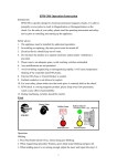
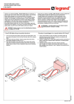
A.V.R. operation manual
PowerMaster
Automatic Voltage Regulator
User Manual
-1-
A.V.R. operation manual
Catalogue
1.
2.
3.
4.
5.
General points for attention…………………………………………………………….2
Product inspection ……………………………………………………………………..2
Panel explanation………………………………………………………………………3
Interior diagram………………………………………………………………………..4
Working environment requirement…………………………………………………….8
6. Preparation before operation…………………………………………………………..8
7. Operating procedure……………………………………………………………………9
8. Treatment for electromagnetic switch jumped…………………………………………10
9. Specification……………………………………………………………………………10
10. Calculation to Capacity…………………………………………………………………11
11. output Voltage and Delay Adjustment…………………………………………………12
12. Line Connection Diagram……………………………………………………………..13
13. Single Phase Interior Diagram…………………………………………………………14
14. Notes for Power Distribution…………………………………………………………..17
15. Power Polarity Judging Method………………………………………………………..17
16. Troubleshooting………………………………………………………………………..18
-2-
A.V.R. operation manual
1. Important Notices
1. Read instructions carefully before operating the AVR.
2. All operating instructions should be followed.
3. Do not overload the maximum capacity of the installation.
WARNING!
Do not insert any object into ventilation holes or other openings.
To reduce the risk of fire or electric shock, install in temperature and humidity controlled indoor area free
of conductive contaminants.
To reduce the risk of fire, replace fuses with the same type and rating when necessary.
CAUTION!
Only qualified personnel should install or service AVR units.
Risk of electric shock, do not remove cover.
qualified service personnel.
No user serviceable parts inside, refer servicing to
2. Product inspection
Each Automatic Voltage Regulator has passed through the most stringent quality control tests at the factory.
When the Automatic Voltage Regulator arrives at the customer’s site, please immediately check the following:
1. Do the model, capacity, voltage setting and serial number of the Automatic Voltage Regulator match with
that ordered by the end user?
2. Check that the Automatic Voltage Regulator has not incurred any physical damage due to transport. Any
damage should be reported to the freight forwarding company and BPC should be connected immediately.
Under no circumstances should you try to connect a damaged Automatic Voltage Regulator into any power
source.
-3-
A.V.R. operation manual
3. Operator Control Panel
1. ON Supply Button: When you push the power (ON) button, critical equipments are connected to the AVR.
2. OFF Supply Button: When you push the power (OFF) button, all power to your critical load is
disconnected.
3. Status Indication Lights: “OK” LED indicator represents normal operation,
“Hi” LED indicator represents that the input voltage is too high,
“Low” LED indicator represents that the input voltage is too low.
4. Output Voltage Changeover Switch: Each of the R.S.T. three phases output voltages can be measured on
the output voltage meter.
5. Output Voltage Indicator Meter.
6. Output Voltage Adjustment: This point is used for adjusting the output voltage meter to zero (when the
mains input power supply is turned off and the output voltage meter does not indicate to zero, you must then
use a screw driver to adjust the indicator to zero)
7. Output Current Changeover Switch: Each of the R.S.T. three phases output currents can be measured on
the output current meter.
8. Output Current Indicator Meter.
-4-
A.V.R. operation manual
4. Internal Component Layout
30~75KVA
1. Mains input power supply switch.
2. Bypass switch (when changing over bypass switch, please firstly interrupt the machine equipment power
supply and then interrupt the master power supply. If there are two switches needed to change over
simultaneously, then the right one is through the automatic voltage regulator and the left one is not , and
after the master power supply switch is pressed on then successively to press the 「ON」power supply switch
on the panel)
3. Input electrical connection terminal. (three or four points referred to connection diagram)
4. Output electrical connection terminal. (three or four points referred to connection diagram)
-5-
A.V.R. operation manual
20~30KVA
5. Electric control circuit board (R.S.T. three pieces)
6. Overload protection fuse (R.S.T. three pieces, provided only for machine model number more than 20K)
7. Bypass over-high voltage protection switch (provide only for machine model number than 45K)
-6-
A.V.R. operation manual
5~15KVA
1. Master power supply switch.
2. Bypass switch ( when changing over bypass switch, please firstly interrupt the machine equipment power
supply and then interrupt the master power supply. If there are two switches needed to change over
simultaneously, then the left one is through the automatic voltage regulator and the right one is not , and
after the master power supply switch is pressed on then successively to press the 「ON」power supply switch
on the panel)
3. Input electric connection place. (three or four points referred to connection diagram)
4. Output electric connection place. (three or four points referred to connection diagram)
5. Electric control circuit board (R.S.T. three pieces)
-7-
A.V.R. operation manual
75~120KVA
1. Master power supply switch.
2. Bypass switch ( when changing over bypass switch, please firstly interrupt the machine equipment power
supply and then interrupt the master power supply, and directed to right through the automatic voltage
regulator and left does not., and after the master power supply switch is pressed on then successively to
press the 「ON」power supply switch on the panel)
3.
4.
5.
6.
7.
Input electric connection place. (three or four points referred to connection diagram)
Output electric connection place. (three or four points referred to connection diagram)
Electric control circuit board (R.S.T. three pieces)
Overload protection fuse (R.S.T. three pieces, provided only for machine model number more than 20K)
Bypass over-high voltage protection switch (provide only for machine model number than 45K)
-8-
A.V.R. operation manual
150KVA~Above
1 Master power supply switch.
2 Bypass switch ( when changing over bypass switch, please firstly interrupt the machine equipment power
supply and then interrupt the master power supply, and directed to upward through the automatic voltage
regulator and downward does not., and after the master power supply switch is pressed on then successively
to press the 「ON」power supply switch on the panel)
3
Input electric connection place. (three or four points referred to connection diagram)
4
5
6
Output electric connection place. (three or four points referred to connection diagram)
Electric control circuit board (R.S.T. three pieces)
Over-high & over low voltage protection bypass switch
-9-
A.V.R. operation manual
5. Working environment requirement
The Normal function operation and use life, in particularly the safety, of the automatic voltage regulator have
been directly influenced on with the working environment and distribution operation, therefore, for proceeding
installation and distribution please necessarily accord the following required indication.
1. Working environment temperature 0℃~40℃, relative humidity 0~95%
2.
3.
If wetting environment, there should take an anti-wet action properly.
The regulator should be installed on the place with good ventilation and kept dryness.
4. To prevent form being etched by oil spray and salty article.
5. To prevent from being steered by dust, cotton wool, and metal powder for avoiding electric components
happened to shortcut or trouble.
6. Do not put articles on the top of the regulator on which there is provided with ventilating holes.
6. Preparation before operation
1. Before operation, please check the following inputted industrial current values:
Is Voltage right?
Is phase number right?
Is grounded line right?
2. When those values are right, still not operating the automatic voltage regulator till all output terminals of
installation such as computer equipment and machine equipment have already been interrupted.
7. Operating procedure
1. Turn on:
Press the inputted non-fuse power switch located at left side or rear of the panel up to the ON position.
Press the button switch with green color down then the green lamp is lighted.
When load is operated, please accord to the turn on operating procedure of computers or equipment.
2. Turn off
Press the button switch with red color down then the red lamp is lighted, and A.V.R. is not operated.
If it wants to have A.V.R. totally non-operated, only press the inputted non-fuse power switch down to
the OFF position.
- 10 -
A.V.R. operation manual
8. Treatment for electromagnetic switch jumped
1. When industrial current is normal:
When the electromagnetic switch is jumped during normal industrial current or within allowance range for
loading machine. At this time, please to interrupt the loading machine switch and then A.V.R. master power
supply switch also.
After then open the left side or rear side panel to change over those simultaneously (refer to interior diagram).
To turn on A.V.R. master power supply switch again and successively to press the 「ON」power supply switch
on the panel, so that the loading machine for the A.V.R. may be operated temporarily. If above-mentioned
problem happened, please contact to our technician for maintenance. For the A.V.R. machine model less than
75K, do not continuously operate for more than 48 hours.
2. When industrial current is abnormal:
When the industrial current is altered up to more than that of allowed input range and output adjustable
range. The electromagnetic switch driven by high-low voltage circuit will interrupt the output power supply. At
this time, please stop making use of the automatic voltage regulator and measure the industrial current voltage
to concern whether that of voltage is too high or too low, and send for a professional electrician to handle.
9. Specification
1. Input voltage altering range: input voltage ±15%( or 25% for specific order).
2. Output Input voltage stability: ±1%
3.
4.
5.
6.
Output voltage adjustable range: 10% above.
Wave distortion: compare to input zero distortion.
Response time: 0.1sec response.
Efficiency : 98% above.
7. Working environment temperature: 0℃~40℃.
8. Humidity: 95%
9. Other characteristics referred to catalogue.
- 11 -
A.V.R. operation manual
10. Calculation to Capacity
1. Firstly understanding the required voltage and total current of an equipment such as computer etc.;
The calculation formula is:
Total Capacity (VA) = Required voltage value (V) ╳Required total current (A)
2. This total capacity is practical consumption power, when A.V.R. capacity is selected.
It is necessary to consider the possibility in future to expand the installation capacity, so that A.V.R.
capacity may be generally added extra 25% at least. Therefore, the A.V.R. capacity is:
A.V.R. practical capacity= Total capacity (VA)*125%
For example:
A computer is operated with voltage 115V and total current 50AMP.
A.V.R (KVA) = 115V*50A/1000*125%
= 5.75KVA*125%
= 7.18KVA
So that preferably selecting a voltage regulator with 7.5 KVA, and accordingly analogized.
- 12 -
A.V.R. operation manual
11. Output Voltage and Delay Adjustment
1. Adjusting output voltage, counterclockwise direction for rising voltage and clockwise direction for lowering
voltage.
2. Adjusting output voltage sensitivity, counterclockwise direction for decreasing sensitivity and clockwise
direction for direction for increasing sensitivity.
3. Adjusting over-high voltage protection, clockwise direction for rising protection voltage and
counterclockwise direction for lowering protection voltage.
4. Adjusting over-low voltage protection, clockwise direction for rising protection voltage and
counterclockwise direction for lowering protection voltage.
5. and 6. Voltage regulation adjustment delay, to insert into a jump line plug for delaying 3~4 sec to start
adjustment. This may extend the use life of A.V.R. in which environment usually has a –high-low voltage
rapid alteration.
7. Over-high or over-low voltage protection delay, to insert a jump line plug for delaying 0.5~1 sec to start
adjustment. This may avoid A.V.R. from error action then the working environment usually has a suddenly high
voltage happened.
- 13 -
A.V.R. operation manual
12. Line Connection Diagram
1. Input voltage line connection section.
2. Output voltage line connecting section.
Notes: 1. when input power is 3Ø3W and output power is 3Ø4W, the neutral line of input voltage is not
connected.
- 14 -
A.V.R. operation manual
12. Single Phase Diagram
2~10KVA
15~30KVA
- 15 -
A.V.R. operation manual
2~10KVA
Rear
Side
Panel
Item
Description
1.
Output Voltage Meter
Input &Output Changeover Switch
2.
(Right→ Output ; Left→ Input)
3.
“ON” indicator
4.
AC Input Mains Switch
5.
Voltage Adjusting Hole(Using a screw driver for adjustment)
6.
Input &Output Terminal
7.
Output Outlet
- 16 -
A.V.R. operation manual
15~30KVA
Power Indicating Light
Output voltage
sensitivity adjustment
1
2
Percentage
±0.8%
ON
ON
ON
OFF ±1%
OFF ON
Using a screw driver for
adjustment, clockwise
direction for rising
voltage.
±1.4%
OFF OFF ±2.3%
Power Supply,
upper for turn on
and down for turn
off
- 17 -
A.V.R. operation manual
14. Notes for Power Distribution
1. A.V.R. have different installing standards according to whose capacity size and various different types of
voltage. Please accord the specification of A.V.R. ordered to select proper power distribution, in particular pay
attention to the diameter of line whether is complied with the specification or not.
2. Please pay attention to input terminal of A.V.R. needed to avoid using the same switch other equipment.
3. Power polarity judging method please referred to the next paragraph of “Power Polarity judging Method”.
4. For three-phase voltage regulator system, in particular, pay attention to the problem of connecting input and
output line phase sequence.
5. For safety, when proceeding line connection, please interrupt power supply and prohibit hot line operation.
6. Please refer to electrical engineering operation rules to proceed line connection.
7. For three-phase voltage regulator system, input power is connected to one end of input power supply switch,
the output power of A.V.R. is connected to output line terminal of terminal disk. Besides, neutral line N and
grounding line G have already marked clear with labels, please accord specification to proceed line connection.
15. Power Polarity Judging Method
1.Hot Line: in respect to hot line(line to line) voltage, there are 190V 200V 208V 220v 230V 380V 400V 415V
440V 480V etc. for three-phase three lines or three phase four lines systems.
2. Neutral line: is also called water line, in respect to hot line voltage, there are 100V 110V 115V 120V 127V
132V 220V 227V etc., in inspect to grounding lint voltage about 0.2V~2.0V. For three-phase three lines system
there is no neutral line.
3. Grounding line: earth of connection point of earth bar or distributor.
4. If the voltage of difference more than 5V in between neutral line and grounding line, or there is a special
requirement for installation system, for keeping the system safety , please send for qualified electrical
technician to reinstall al good earth system.
5. For three-phase four lines system the general voltage is as follows:
110V/190V 115V/200V 120V/208V 127V/220V 132V/230V 220V/380V 230V/400V 240V 415V 254V/440V
277V/480V
6. For three-phase three lines system the general voltage is as follows:
190V 200V 208V 220V 230V 380V 440V 480V.
7. For single phase two lines systems is as follows:
100V 10V 115V 120V 127V 132V 220V 254V 227V.
8. Hot line marked method: for single phase system, marked as L, L1, L2, for three system , marked as R, S, T,
U, V, W.
9. Neutral line i.e. water line mark: single phase system and three-phase system are all marked as N.
10. grounding line marked as “G” or used the symbol “
- 18 -
“
A.V.R. operation manual
16. Troubleshooting
To maintain A.V.R. is easier to proceed only by use of a three proposed (digital type) electric meter.
Phenomenon
Checking Method
Troubleshooting
1.
Output power interrupted
Is power failure?
Turn on the power supply
again.
If NFB or electromagnetic
switch jumped is resulted from
overload, then check whether
the load power circuit is
Is NFB or electromagnetic
switch jumped?
normal.
2.
Temperature increasing and
Fan damaged.
Check whether the fan stops
operation.
Interrupt power and remove fan
terminal, and renew a fan
within short-term.
3.
Output current much more than
rated current.
Is there a trouble for load?
Do there have new equipment
installed?
Is current meter troubled?
Please check the load.
Please renew a A.V.R. with
larger capacity.
Renew a current meter.
4.
Output voltage higher.
Is PCB troubled?
Does output voltage happen to
phase lagged?
Renew PCB.
Repair input power supply
again.
Is voltage meter troubled?
Is VR loose?
Renew a voltage meter.
Adjust VR to rated value.
Is current overloaded?
Is three-phase too unbalanced?
Is voltage meter troubled?
Is VR loose?
Remove some load equipment.
Redistribute load.
Renew a voltage meter.
Adjust VR to rated value.
5. Output voltage lower.
When A.V.R. is troubled and at same time the machine installation should not be stopped and user
also hard to find out the trouble reason. Please change over the knife switch located within the
installation to bypass for temporarily stopping operation (referred to page 4section 2), and then
contact us immediately.
- 19 -