1
BeagleBone 3.1MP Camera Cape
5.3
System Reference Manual
Rev A1
Camera Interface (CAM I/F)
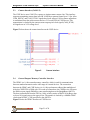
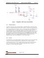
The CSSP device uses CAM I/F to connect to Aptina camera sensor chip. This interface
supports transmitting camera data in RAW 10-bit Bayer pattern format up to 12 fps. After
CAM_HSYNC and CAM_VSYNC signals have been asserted, 10-bit camera output data
is transmitted from the camera sensor and to a 512-word FIFO of CSSP device. This
transmission is clocked by the camera sensor output pixel clock signal (CAM_PCLK).
All signals are at 2.8V voltage level.
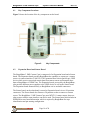
Figure 5 below shows the camera interface on the CSSP device.
Figure 5.
5.4
Camera interface
General Purpose Memory Controller Interface
The GPMC is a 16-bit external memory controller, which is used for communication
between standard memories and a wide range of external devices. The connection
between the GPMC and CSSP devices is a 16-bit synchronous address/data-multiplexed.
After the CSSP FIFO is filled with 128 words of camera data, the CSSP device will assert
the DMA request signal (DMAR) to start transferring data to the BeagleBone AM335x.
The data is transferred from the FIFO as 16-bit, which consists of RAW 10-bit Bayer data
as lower 10-bit and zeros as the upper 6 bits. The transfer is clocked by a 48MHz GPMC
clock signal (GPMC_CLK) provided by the AM335x.
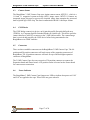
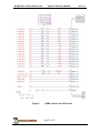
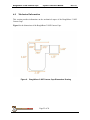
Figure 6 shows the GPMC interface on CSSP device.
Page 21 of 26