1
BeagleBone 3.1MP Camera Cape
5.5
System Reference Manual
Rev A1
Power Supply
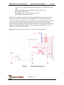
The BeagleBone Camera Cape generates 1.8V and 2.8V power supplies for I/O signals of
CSSP device as well as the camera sensor. Two low-dropout (LDO) voltage regulators
TPS73701 are used to regulate VDD_1V8 and VDD_2V8 power rails. The LDO’s are on
when their enable pins are pulled high and go to shutdown mode when the enable inputs
are low. These enable pins are controlled by a GPIO signal, GPIO0_5, which can be
accessed at pin 17 of P2 connector.
5.6
Voltage Translator
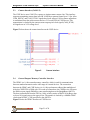
Voltage translations are required on the Sensor board to bring the signals from
BeagleBone down to the voltage level of camera sensor. These signals include the I2C2
bus, CAM_RST, and CAM_MCLK.
5.7
EEPROM
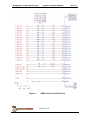
The BeagleBone 3.1MP Camera Cape has an EEPROM containing information that will
allow the SW to identify the board and to configure the expansion headers pins as
needed. EEPROMs are required for all Capes sold in order for them to operate correctly
when plugged in the BeagleBone.
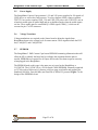
The EEPROM used on this cape is the same one as is used on the BeagleBone, a
CAT24C256. The CAT24C256 is a 256 kb Serial CMOS EEPROM, internally organized
as 32,768 words of 8 bits each. It features a 64-byte page write buffer and supports the
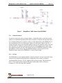
Standard (100 kHz), Fast (400 kHz) and Fast-Plus (1 MHz) I2C protocol. Figure 7 is the
design of the EEPROM circuit.
Page 23 of 26