1
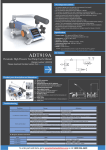
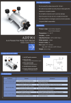
ADT209/210 Loop Calibrator
ADT209/210 Loop Calibrator
User Manual
(Version number: 1508V01)
Additel Corporation.
Statement
This manual is applicable to the ADT209/210 loop calibrator designed and produced by the
Additel Corporation. This manual is written in English. If there are any discrepancy in the content
of different language versions, the English version shall prevail. This manual subject to change
without prior notice.
CONTENTS
1. Warning Notice……………………………………………………………………………………………………………1
2. Product Description………………………………………………………………………………………………………1
3. Basic Structure……………………………………………………………………………………………………………2
4. Keypad function……………………………………………………………………………………………………………3
5. Display………………………………………………………………………………………………………………………4
6. Boot display………………………………………………………………………………………………………………5
7. Main Function Operation…………………………………………………………………………………………………6
7.1 Measurement/Output Switch………………………………………………………………………………………………6
7.2 Backlight Brightness Adjustment…………………………………………………………………………………………6
7.3 Keypad Lock………………………………………………………………………………………………………………6
7.4 Voltage Measurement……………………………………………………………………………………………………6
7.5 Current Output/Simulate Transmitter Output………………………………………………………………………………8
7.5.1 Range Switching………………………………………………………………………………………………………9
7.5.2 Function Selection……………………………………………………………………………………………………9
7.5.3 Output Value Adjustment………………………………………………………………………………………………9
7.5.4 Automatic Ramp/step Output………………………………………………………………………………………10
7.6 Current Measurement/Loop Transmitter mA Measurement………………………………………………………………10
7.6.1 Range Switching……………………………………………………………………………………………………10
7.6.2 Function Selection……………………………………………………………………………………………………11
8. Menu Operation…………………………………………………………………………………………………………12
8.1 Menu Structure……………………………………………………………………………………………………………12
8.2 Menu Operation…………………………………………………………………………………………………………13
I
8.2.1 Enter/Return To Menu………………………………………………………………………………………………13
8.2.2 Switch Menu Items…………………………………………………………………………………………………13
8.2.3 Modify Setting Menu Parameter……………………………………………………………………………………13
8.2.3 Data Entry……………………………………………………………………………………………………………13
8.3 Auto Shutdown Setting……………………………………………………………………………………………………13
8.4 Automatic Shutdown Backlight Setting……………………………………………………………………………………13
8.5 Measurement Filter Parameter Setting………………………………………………………………………………… 14
8.6 Automatic Ramp/Step Output Setting……………………………………………………………………………………14
8.6.1 Ramp/Step Switch……………………………………………………………………………………………………14
8.6.2 Direction Setting……………………………………………………………………………………………………14
8.6.3 Ramp/Step Time Setting……………………………………………………………………………………………14
8.7 Clear Menu Setting………………………………………………………………………………………………………15
8.8 Software/hardware Version………………………………………………………………………………………………15
8.9 Self-test…………………………………………………………………………………………………………………15
8.9.1 Self-test Description…………………………………………………………………………………………………15
8.9.2 Self-test Item Switch…………………………………………………………………………………………………15
8.9.3 Self-test Item Description……………………………………………………………………………………………16
8.10 Calibration………………………………………………………………………………………………………………18
8.10.1 Calibration Condition………………………………………………………………………………………………18
8.10.2 Calibration Item……………………………………………………………………………………………………18
8.10.3 Calibration Process…………………………………………………………………………………………………18
8.10.4 Restore Factory Calibration Data…………………………………………………………………………………19
9 Specification………………………………………………………………………………………………………………19
9.1 Main Specification………………………………………………………………………………………………………19
II
9.1.1 DC Voltage Measurement……………………………………………………………………………………………………19
9.1.2 DC mA Measurement/Loop Transmitter Current Measurement……………………………………………………………19
9.1.3 Source/sink DC Current Output………………………………………………………………………………………………20
9.1.4 Mechanical/live Switch Measurement………………………………………………………………………………………20
9.2 General Specifications………………………………………………………………………………………………………………20
10. Replace The Battery……………………………………………………………………………………………………22
11. Manufacturer Information……………………………………………………………………………………………23
III
I. Warning Notice
◆ Before using this instrument, please make sure you have read and understand the user manual.
◆ Inspect the calibrator for any damages before use.
◆ Do not apply more than 30V between any two terminals or between any terminal and ground.
◆ When using the calibrator to measure or output the correct wiring, mode and range must be used.
◆ To avoid any potential damage to other devices when testing, please adjust the calibrator to the correct mode before
connecting the test leads.
◆ Replace the batteries as soon as the battery symbol flashes.
◆ Before removing the battery door, remove all test leads from the calibrator.
2. Product Description
ADT209/210 is a multi-function, durable, hand-held loop calibrator. This calibrator offers six primary functions: current
output, analog transmitter output, voltage measurement, switch measurement, transmitter loop measurement, and current
measurement. Each unit comes in a compact, ergonomic design such that the calibrator can be operated easily with one
hand. The large, high contrast VA screen clearly displays the results. Each unit comes standard with an IP54 rating.
The ADT209 provides 0.03%RD accuracy, while the ADT210 provides higher accuracy as 0.01%RD.
1
3. Basic Structure
Model label
Case
Battery
compartment
210 Loop Calibrator
Display
Protective
case
Adapter
jack
Keypads
25%
100%
Range
Math
Nameplate
ADT210 Loop Calibrator
Auto
Hold
Mode
COM
30V
+
Measuring
jack
Powered by 9V Alkaline
battery or specified
adapter.
Additel Corporation,USA
www.additel.com
2
4. Keypad function
measure/output
interface
menu setting
interface
measure/output
interface
Long press -> on/off
menu setting
interface
Short press -> Cancel/
Return to previous menu
measure/output Short press -> Move left
interface Long press -> Auto ramp/step
25%
Range
menu setting Short press -> Enter last menu
interface
/ Move left
100%
Math
Short press -> 25% step
Long press -> Switch range
N/A
measure/output Short press -> 100% Span
interface Long press -> Switch function
menu setting
interface
Short press -> Swith calibration
point/ Set ramp start point
Auto
measure/output Short press -> Change function
mode
interface
Long press -> Enter the menu
menu setting
Short press -> Switch modes
interface
measure/output
interface
Short press -> Decrease by 1
menu setting Short press -> Decrease/Switch
interface parameter level of menu
3
Mode
Hold
measure/output
interface
Short press -> Increase by 1
menu setting
interface
Short press -> Increase by 1 /
Switch menu parameter level
measure/output Short press -> Move right
interface Long press -> Adjust backlight
menu setting
interface
Short press -> Enter next menu
/ Move right
measure/output
interface
Short press ->Confirm
Long press -> Lock/Unlock
menu setting
interface
Short press ->Confirm
5. Display
mA output
Simulate transmitter
output
mA
measurement
Loop transmitter
mA measurement
Voltage
measurement
Switch
measurement
Range
Battery indicator
Keypad lock
Automatic ramp
Engineering
function
Automatic step
Filter icon
Main display
Calibration
standard
Sub display
Engineering unit
Function
indication
Progress bar
Menu
Auto off
Auto light
Filtering
Ramp/Step
Clear
Software/hardware
version
Self-test
Calibration
4
6. Boot display
Full Screen
Voltage Measurement
5
Software version
/hardware version
7. Main Function Operation
7.1 Measurement/Output Switch
ADT209 and ADT210 provide the following functions:
◆Voltage Measurement
◆Switch measure
◆Current output
◆Simulate transmitter output
◆Current measurement
◆Loop transmitter current measurement
In the measurement/output interface, you can press
Mode
to switch through above functions.
7.2 Backlight Brightness Adjustment
In any non-input screen, you can press and hold
to adjust backlight brightness(3-level brightness adjustment).
7.3 Keypad lock
In the measurement/output interface, you can press and hold
Hold
to lock/unlock the keypad.
7.4 Voltage Measurement
Voltage measurement interface can simultaneously display voltage measurement value and percentage of range, you
can press and hold
25%
Range
to switch the current range, the voltage measurement has 3 ranges:
◆0 ~ 30V (0% ~ 100%) [default]
◆1V ~ 5V (0% ~ 100%)
◆0 ~ 10V (0% ~ 100%)
6
210 Loop Calibrator
25%
100%
Range
Press
Math
Mode
Auto
to display
Hold
Mode
COM
30V
+
The maximum
voltage of 30V DC
-
+
Fig 7.1 Voltage Measurement
7
MEASURE V
7.5 Current Output/Simulate Transmitter Output
In current output mode(As Fig 7.2), the calibrator supplies DC current with loop power.In simulate transmitter mode
(As Fig 7.3), the calibrator simulates a two-wire transmitter that has external power supply.
210 Loop Calibrator
DC output
25%
Each press Range
can increase or
reduce by 25% of
the current full scale
in stepwise manner
25%
Auto
Hold
Mode
30V
to
switch the automatic
step/ramp output
Auto
Hold
Mode
COM
Press
Math
Auto
+
Mode
100%
Range
Math
Long press
COM
Press
25%
100%
Auto
to
switch the automatic
step/ramp output
210 Loop Calibrator
25%
Each press Range
can increase or
reduce by 25% of
the current full scale
in stepwise manner
Range
Long press
Simulate transmitter
output
30V
+
Mode
to display
to display
-
+
Fig 7.2 Current Output
-
+
Fig 7.3 Simulate Transmitter Output
8
7.5.1 Range Switching
25%
In the current output/simulate transmitter output interface, you can press and hold
Range
key to switch the current
range.Current output/simulate transmitter output has 3 ranges:
◆ 4 ~ 20mA (0% ~ 100%) [default]
◆ 0 ~ 20mA (0% ~ 100%)
◆ 0 ~ 24mA (0% ~ 100%)
7.5.2 Function Selection
In the current output/simulate transmitter output interface, you can long press
100%
Math
to switch the percentage
calculation. Current output/simulate transmitter output provides three calculation functions:
◆ Linear, [default]
◆ Square
◆ Valve
7.5.3 Output Value Adjustment
In the current output/simulate transmitter output interface, you can press
current range. You can press
100%
Math
25%
Range
to adjust the output value by 25% of
key to output 0% and 100% of full scale. Press
key or
key to adjust by an
integer by 1mA.
You can press
the cursor. Press
9
Auto
key or
or
key, the cursor will blink in the main display. Press
to increase or decrease the value.
Auto
or
to adjust the position of
7.5.4 Automatic Ramp/Step Output
In the current output/simulate transmitter output function,
Auto
you can press and hold
step output. Press andhold
Long press
25%
Range
key to select auto ramp/automatic
100%
Math
key to switch output function.
key to switch range and press
100%
Math
210 Loop Calibrator
Loop transmitter
current measurement
key to
select a starting point.
You can press
key to start output, and press again
Hold
key to pause the output. Press
Hold
to exit automatic ramp/
25%
100%
Range
automatic step menu.
Press
7.6 Current Measurement/Loop Transmitter mA Measurement
Math
Mode
Auto
to display
Hold
Mode
Loop transmitter mA measurement provides 24V loop power, and
COM
also can measure the current value in the loop. In this mode(As Fig
30V
+
7.4), the circuit power has series resistor greater than 250Ω, which
can be compatible with HART devices without using external resistor.
-
7.6.1 Range Switching
In the current measuring/loop transmitter mA measurement
interface, long press
25%
Range
Max. 30V DC voltage
key to switch current range. The current
Dual Cable
Transmitter
+
Fig 7.4 Loop Transmitter Current
Measurement Configuration
10
measurement/loop transmitter mA measurement has three ranges:
◆ 4 ~ 20mA (0% ~ 100%) [default]
◆ 0 ~ 20mA (0% ~ 100%)
◆ 0 ~ 24mA (0% ~ 100%)
7.6.2 Function Selection
In the current measuring/loop transmitter mA measurement interface, long press
100%
Math
key to switch the
percentage calculation function. The current measurement/Loop transmitter mA measurement provides two
calculation functions:
◆ Linear, [default]
◆ Square
11
8. Menu Operation
8.1 Menu Structure
No automatic shutdown
Backlight shutdown
time(min)
Always on
First order filtering coefficients
(the greater the value
is,the more obvious
the filtering effect is)
Close filter
15
30
60
120
OFF
1
5
10
ON
2
3
……
Automatic shutdown
time(min)
Automatic
shutdown settings
Automatic shutdown
backlight settings
Filter parameter
settings
10
OFF
1.Automatic ramp parameter settings
2.Automatic step parameter settings
See 8.6 automatic ramp/step
output settings
Ramp/step parameter
settings
Calibration
System self-test
Software/hardware
version
Measurement clear
setting
1.Calibration
2.Restore factory settings
See 8.10 Calibration
1.Battery voltage detection
2.Board voltage detection
3.Loop Power Supply Voltage
Detection
4.Current output/measurement
5.Switching measuring self-test
6.LCD segment code complete
detection
1.SV-software version
2.HV-hardware version
1.Clear voltage measurement
2.Clear current measurement
12
8.2 Menu Operation
8. 2.1 Enter/Return to menu
In the measurement/output display interface, long press
In any menu button, you can press
Mode
key to enter the settings menu.
key to return to the previous short menu until you exit.
8.2.2 Switch Menu Items
In the menu interface, you can press
Auto
or
to toggle the items along the menu bar:
8.2.3 Modify Setting Menu Parameter
You can press
or
to switch the setup parameters of current menu.
8.2.3 Data Entry
◆
Hold
Cancel data input
◆
◆
Confirmation/ enter data
Auto
Move the cursor left/right
◆
Increase/decrease by 1
8.3 Auto Shutdown Setting
In the automatic
shutdown menu, press
or
to select auto shutdown time, 15/30/
60/120 minutes are optional, or OFF (no auto shutdown).
8.4 Automatic Shutdown Backlight Setting
In the auto
13
shutdown backlight menu, you can press
key or
key to select the auto
backlight shutdown t time, 1/5/10 minutes are optional, or ON (the backlight is always on).
8.5 Measurement Filter Parameter Setting
In the filter adjustment menu
if the measurement is voltage, current or loop transmitter
current, the filter coefficients will be displayed directly. If there are other items, you can press
Mode
key to switch between
measurement items.
Press
key or
key to select first order filtering coefficients, 2…10 are optional (the larger the value, the more
obvious the filtering effect) or OFF (no filter).
8.6 Automatic Ramp/Step Output Setting
8.6.1 Ramp/Step switch
In the automatic ramp/step setup menu press
Mode
key or
Auto
key to switch between automatic ramp output
setting and automatic step output setting.
8.6.2 Ramp Direction Setting
In the automatic ramp/step setting menu press
This icon
100%
Math
to set automatic ramp/step direction.
means the direction is 0%→100%→0% or 100% →0%→100%, and
means the 0%→100%
or 100%→0%.
8.6.3 Ramp/Step Time Setting
In automatic ramp/step setting menu press
and press
Hold
key to enter the time setting. Press
key to increase or decrease by 1 second.By pressing the
Hold
Auto
key to move the cursor
key again will confirm the entry or
14
press
key to cancel the entry.
8.7 Clear Menu Setting
In the clear setting menu
menu, you can press
Hold
,In the voltage measurement clear or current measurement clear
key to preform clear operation, the cleared measurement value will be observed in the main
display interface.
8.8 Software/hardware Version
In the software/hardware version browse menu
version is 1-01, sub display area
, main display area
indicates that the software
indicates the hardware version is 1-01.
8.9 Self-test
8.9.1 Self-test Description
When performing self-test, you will need to short the electrical measuring port. Self Test menu item contains the
following self-tests: supply voltage detection, system voltage detection, loop power/voltage measurement self-test, current
output/current measurement self-test, switch measurement self-test, and LCD test.
8.9.2 Self-test Item Switch
In the self-test menu
detection, system voltage detection, etc.).
15
, you can press
Mode
key to toggle self-test items (e.g. supply voltage
8.9.3 Self-test Item Description
Test Item
Range
Interface Schematic
Supply voltage detection
Supply voltage: 6V ~ 10V
System Power Detection
a.3.3V Voltage: 3.2V ~ 3.4V
b.5V Voltage: 4.8V ~ 5.2V
Loop supply voltage /voltage
measurement self-test
Current Output/Current
Measurement Self test -4mA
Notes
a.If the power is supplied only by
the battery, the displayed voltage
will be the battery voltage
b.If you insert the power adapter,
the displayed voltage will be the
adapter voltage
_
22V~25V
If the range is exceeded additional
troubleshooting or calibration may
be required.
3.9mA~4.1mA
If the range is exceeded
calibration is required.
16
Current Output/Current
Measurement Self test -20mA
17
19.9mA~20.1 mA
If the range is exceeded
calibration is required.
Switch measurement selftest - OPEN
The main display area
displays OPEN
_
Switch measurement
self-test - CLOSE
The main display area
displays CLOSE
_
LCD Detection
All pixels will illuminate
_
8.10 Calibration
We recommend your calibration standards to be at least four times more accurate than the ADT210.
8.10.1 Calibration Condition
Note: Ensure the following critera are meet during the calibration:
◆Ambient temperature 20℃ 2℃; relative humidity 45%-75%; atmospheric pressure 86kPa-106kPa.
◆Allow at least a 15 min warmup time for the ADT210.
8.10.2 Calibration Item
ADT210 2-point calibration:
◆Voltage measurement: calibration points are 0 and 30V
◆Current measurement: calibration point are 4 and 20mA
◆Current output: calibration point are 4 and 20mA
8.10.3 Calibration Process
1) Select the
press
Hold
calibration menu, you can press
Hold
key, and enter the password “310” and
key to confirm.
2) Press
Mode
key to toggle between calibration items(the first screen is default to current output calibration item).
3) Press
100%
Math
to browse the calibration data, and toggle between calibration points.
4) Press
Hold
to enter the calibration value.
◆Current output calibration: enter the value displayed by the current calibrator by pressing
or pressing
Hold
key to confirm entry
key to cancel the entry.
18
Current measurement/voltage measurement calibration: When sourcing the standard value press the
◆
to confirm the entry or press
5) Press
100%
Math
Hold
key
key to cancel the entry.
to switch to the next calibration point, repeat step 4).
8.10.4 Restore Factory Calibration Data
Note: when restoring factory calibration data, all other settings parameters will be reset to factory settings.
Select the
Hold
calibration menu, you can press
Hold
to enter, and enter password “310”. Press
key to confirm, the system will reboot.
9 Specification
9.1 Main Specification
◆Specifications are based on 1 year and an environmental temperature of 10°C to 30°C .
◆Temperature coefficient: -10°C~10°C and 30°C~50°C: ±0.005%FS/°C
9.1.1 DC Voltage Measurement
◆Range:0~30V
◆Resolution:1mV
◆Input impedance:1MΩ
◆Accuracy:ADT209:±(0. 03%RD + 2mV)
ADT210:±(0.01%RD + 2mV)
9.1.2 DC mA Measurement /Loop Transmitter Current Measurement
◆Range:0~24mA
◆Resolution: 1μA
19
◆Accuracy: ADT209:±(0. 03%RD + 2μA)
ADT210:± (0.01%RD + 2μA)
◆Loop transmitter current measurement: maximum load 700Ω
9.1.3 Source/Sink DC Current Output
◆Range: 0~24mA
◆Resolution:1μA
◆Accuracy: ADT209:±(0. 03%RD + 2μA)
ADT210:±(0.01%RD+2μA)
◆Source mode:Maximum load 700Ω/20mA
◆Sink mode: External loop voltage nominal 24V, maximum 30V, minimum 12V
9.1.4 Mechanical /Live Switch Measurement
◆Equipment:
* Input
impedance: greater than 500MΩ
◆Charged:
* Input
impedance: greater than 500MΩ
* Trigger
level: low <0.3V, high> 2V
9.2 General Specifications
◆Pressure: Maximum voltage between any terminals and ground or between any two terminals:30V
◆Storage Temperature: -20℃ ~ 70℃
◆Operating Temperature: -10℃ ~ 50℃
20
◆Relative Humidity:
* 95%/30℃
* 75%/40℃
* 45%/50℃
◆Operating altitude: Maximum 3000m
◆Vibration Shock:
* Random
* 1m
2g, 5 to 500Hz
drop
◆Power Requirements: A 9V alkaline battery (ANSI/NEDA 1604A or IEC6LR61) or standard DC9V adapter
◆Battery Life:
* Output
mode:18 hours(12mA /500Ω)
* Measurement
mode:50 hours
◆Dimensions: 163mm(L) × 83mm(W) × 41mm(H) (with holster)
◆Weight: 350g (with holster)
◆Protection class: IP54
◆Certification: CE
21
10. Replace the battery
Warming:
◆To avoid false readings, the battery should be replaced immediately when the display indicates that the battery is low or
does not start properly
◆Use a 9V alkaline battery (ANSI/NEDA 1604A or IEC6LR61)
Battery replacement:
1) Disconnect test lead from the input signal;
2) Long press
key to turn off the calibrator
3) Remove the protective cover;
4) Open the battery door behind the calibrator;
5) Remove the battery;
6) Insert the replacement battery to make sure the
battery polarity is correct;
7) Replace the battery door and determine that the
batteries are in place;
8) Place the calibrator into the leather.
10.1 Replace the battery
22
11. Manufacturer Information
Additel Corporation
22865 Savi Ranch Parkway Ste F
Yorba Linda, CA 92887, USA
Phone: 714-998-6899
Email: [email protected]
Website: www.additel.com
23
Additel Corporation
22865 Savi Ranch Parkway Ste F
Yorba Linda, CA 92887, USA
Phone: 714-998-6899
Email: service @additel.com
website: www.additel.com