1
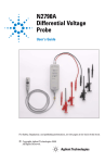
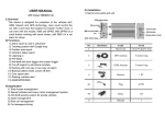
sA
User’s Guide
Publication number N2772-92002
September 2002
For Safety, Regulatory, and publishing information, see the pages at the back of this book.
©
Copyright Agilent Technologies 1999-2002
All Rights Reserved.
N2772A Differential Voltage Probe
Contents
Inspect the Probe 3
Compatibility 4
Probe Parts Supplied 5
Characteristics and Specifications 6
Electrical Characteristics 6
Input Characteristics 7
Output Characteristics 7
Environmental Specifications 7
Safety Specifications 8
Using the N2772A Probe 10
Powering the N2772A 10
External Power Supply 10
Install or Replace the Battery 11
Oscilloscope Input Characteristic 11
Select the Correct Attenuation 12
Measurement Tips 12
Calibration Testing Procedures 14
Cleaning the Probe 18
2
N2772A Differential Voltage Probe
Inspect the Probe
Inspect the Probe
❏ Inspect the shipping container for damage.
Keep a damaged shipping container or cushioning material until the contents of
the shipment have been checked for completeness and the probe has been
checked mechanically and electrically.
❏ Check the accessories.
Any accessories that were supplied with the probe are listed in “Probe Parts
Supplied” this manual.
• If the contents are incomplete or damaged, notify your Agilent Technologies
Sales Office.
❏ Inspect the instrument.
• If there is mechanical damage or defect, or if the probe does not operate
properly or pass calibration tests, notify your Agilent Technologies Sales
Office.
• If the shipping container is damaged, or the cushioning materials show signs
of stress, notify the carrier as well as your Agilent Technologies Sales Office.
Keep the shipping materials for the carrier’s inspection. The Agilent
Technologies office will arrange for repair or replacement at Agilent
Technologies’ option without waiting for claim settlement.
3
N2772A Differential Voltage Probe
Inspect the Probe
N2772A Differential Voltage Probes
The N2772A differential probe allows you to safely measure floating circuits, as
high as 600V dc peak to ground, with the oscilloscope grounded. It is ideal for
many applications such as motor speed controls, power supply designs and
electronic high-power converters.
With 20 MHz bandwidth, switchable attenuation of 20:1 and 200:1, and a
maximum voltage input of 600V, it provides the versatility for a broad range of
applications including high-voltage circuits.
Each probe comes with sharp probe tips for use on small components and in tight
places and alligator clips for connecting to larger cables.
The probe is powered by a 9V battery or by using a separate power supply, the
N2773A.
Compatibility
The N2772A differential probe is compatible with any oscilloscope that has the
following features:
• 1 M Ω input impedance
• Can display 30V peak input
• Has BNC input
4
N2772A Differential Voltage Probe
Inspect the Probe
Probe Parts Supplied
The following diagram and table show the parts supplied with the N2772A Probe.
3
2
1
Parts for N2772A Probe
Item
1
2
3
4
5
6
Description
Differential voltage probe
Probe tips
Banana jack alligator - black
Banana jack alligator - red
Hook Retractable - black
Hook Retractable - red
Part Number
N2772-60001
5063-2188
5063-2189
5063-2187
5063-2191
5063-2190
5
N2772A Differential Voltage Probe
Characteristics and Specifications
Characteristics and Specifications
Characteristics and specifications for the N2772A Differential Voltage Probe are
shown below.
Electrical Characteristics
Attenuation ratios
Bandwidth (into 1 M Ω , 50 pF)
Accuracy
Rise Time
High CMRR
Input impedence
Output impedence
Noise
Offset
Switch positions
External power
Internal power
Power indicators
Auto stand by
*Battery life measured @ 25
6
20:1 and 200:1 (Selectable via switch on probe.)
20 MHz
± 2.5% into 1 M Ω
200x: 17.5 ns
20x: 17.5 ns
80 dB @ 60Hz, 50 dB @ 1 MHz
Between inputs: 10 M Ω , 5 pF
50 Ω
200x: <2 mVrms
20x: <3 mVrms
<=10 mV into 1 M Ω
OFF, 200x, 20x
Via power adapter N2773A (optional)
Battery power: Alkaline 9V, IEC6LR61
Battery life: 8 hour operation, 400 hour in auto
standby*
Green LED: ON at normal operation. Blinks at
standby.
Red LED: ON when battery needs to be replaced.
After 30 minutes, only when battery operated.
° C with Duracell® akaline battery. (Delivered with probe.)
N2772A Differential Voltage Probe
Characteristics and Specifications
For derating of each input probe (red or black), see the figure below.
Input Characteristics
Input probe tip style
Shrouded banana probe tip
Probe cable length
1.5 meter (60 inches)
Maximum input voltage to ground600V CAT III
1000V CAT II
Maximum differential input
1000 VDC, or
voltage
1000 Vrms, or
1200V (DC + AC peak)
Output Characteristics
Output Characteristics
Output cable
Safety designed BNC cable
Cable length
0.5 meter (20 inches)
Maximum output voltage range ± 6.5 V into 1 M Ω
Environmental Specifications
Temperature
Altitude
Operating: 0 °C to +50 °C (+32 °F to +122 °F)
Storage: -10 °C to +60 °C (+14 °F to +140 °F)
Operating: 3 km (9850 feet)
Storage: 12km (40,000 feet)
7
N2772A Differential Voltage Probe
Characteristics and Specifications
Table 1
Frequency range:
10 kHz to 25 MHz
20x
200x
Frequency range:
25 MHz to 1 GHz
20x
200x
E = 3 V/m
Susceptibility
(in % of full dynamic range)
E = 10 V/m
<1%
<1%
E = 3 V/m
<1%
<1%
E = 10 V/m
<=1%
<=1%
<=2%
<=2%
Safety Specifications
Meets requirements of:
Compliant with:
EN61010-2-31 (IEC1010-2-31)
UL3111-1 (including listing)
CSA C222.2 No. 1010.1-92 (approval: pending)
Max floating output voltage 600V Category III, up to 400Hz. (From shielding to
ground.)
8
N2772A Differential Voltage Probe
Characteristics and Specifications
W A R N I N G SHOCK HAZARD!
These probes are designed for use with oscilloscopes that have a common
terminal at GROUND POTENTIAL (in accordance with OSHA requirements and
!
the National Electric Code). Exposed metallic surfaces of the probe and the
oscilloscope MUST BE GROUNDED. Failure to ground the common terminal
during certain applications, such as those requiring the oscilloscope to be
powered from an external battery, might expose the operator to an electrical
shock hazard that could be lethal (depending on voltage and current conditions.)
W A R N I N G Do the following to avoid electrical shock or fire if the probe is connected to
more than 42V peak (30V rms):
• Use only the N2773A power adapter or a 9V battery.
• Connect the power adapter to the AC outlet before connecting it to the
N2772A.
• Do not insert metal objects in the power adapter connector.
• Use 600V rated test lead adapters. The maximum allowable input
voltage is 600V, Category III.
!
This symbol signifies that the N2772A Differential Probe is protected by
double or reinforced insulation. Only use specified replacement parts
when servicing the instrument.
This symbol signifies CAUTION! and requests that the user refer to the
user manual before using the instrument.
9
N2772A Differential Voltage Probe
Using the N2772A Probe
Using the N2772A Probe
Powering the N2772A
The N2772 probe can be powered either by an internal 9V battery or the N2773A
power supply. The battery has a limited life. For this reason the probe has a LOW
BATTERY indicator and will automatically switch to STAND BY mode after
approximately 30 minutes. If you store the probe for extended periods of time,
remove the battery and store it separately.
External Power Supply
For convenience the N2773A power supply is recommended. When you use this
power supply, take care to select the appropriate voltage with the switch on the
rear of the probe power supply. The power source has been designed to provide
the correct power with 50 Hz, 60 Hz and 400 Hz sources of 115V and 230V.
10
N2772A Differential Voltage Probe
Using the N2772A Probe
Install or Replace the Battery
W A R N I N G Never install or replace the battery while the probe is connected to a voltage
source. Replace the battery when the red LED is lit, or when both red and green
LED's are off when the probe is switched on.
!
The expected battery life is 8 hours of operation and 400 hours in auto standby.
Oscilloscope Input Characteristic
The probe has been designed to drive a 1M Ω input to maximize battery life. The
input capacitance of the oscilloscope should be < 50 pF.
11
N2772A Differential Voltage Probe
Using the N2772A Probe
Select the Correct Attenuation on the Probe and the Oscilloscope
The probe has two modes of operation, 20:1 and 200:1 attenuation. Select the
desired attenuation on the probe and the correct probe attenuation setting on
the oscilloscope. This will ensure that accurate voltage readings can be made
directly from the oscilloscope.
Measurement Tips
• Use the 20x range on the differential voltage probe for smaller signals,
such as ripple on a high voltage reference lead.
• When the probe is battery operated, the red LED indicates that the
battery level is low and the battery needs to be replaced.
• When battery operated, the probe automatically goes to standby mode
after 30 minutes to conserve battery power. A blinking green LED
indicates that the probe is in standby mode. To continue operation, turn
the range selection switch from OFF to 20x or 200x.
• Connect the red probe cable to a more positive or more negative voltage
level than the black probe cable.
12
N2772A Differential Voltage Probe
Service Strategy
Service Strategy
For repair, calibration, and to ensure the N2772A performs to its warranted
specifications, send the probe to an Agilent Service Center for calibration testing
procedures. The probe should be tested once a year or as required by other
standards. If repair is needed and the N2772A is under warranty, normal warranty
services will apply. If the N2772A is not under warranty, repair costs will be
applied.
To return the Probe to Agilent Technologies for Service
Call (877) 477-7278 for further details and the location of your nearest Agilent
Technologies Service Office.
1 Write the following information on a tag and attach it to the probe.
• Name and address of the owner
• Probe model number
• Description of service required or failure indication
2 Retain all accessories.
3 Return the probe in its case or pack the probe in foam or other
shock-absorbing material and place it in a strong shipping container.
You can use the original shipping materials or order materials from an
Agilent Technologies Sales Office. If neither are available, place 3 to 4
inches of shock-absorbing material around the instrument and place it
in a box that does not allow movement during shipping.
4 Seal the shipment container securely.
5 Mark the shipping container as FRAGILE. In all correspondence, refer
to the instrument by model number and full serial number.
13
N2772A Differential Voltage Probe
Calibration Testing Procedures
Calibration Testing Procedures
These procedures are used to test the warranted specifications for the N2772A
Differential Probe. The recommended calibration test interval for the N2772A is
once a year or as required. Use the equipment listed in the “Test Equipment
Required” section to complete the Calibration Testing Procedures.
Required Test Equipment
Description
Minimum Requirements
Multimeter
8.5 digits of resolution
Oscilloscope
100 MHz
Calibrator
DC Voltage 0 to ± 1100 V
Programmable Function 50 MHz sine wave
Generator
N2772A probe with N2773A power supply
Part Number
3458A
54622A
Fluke 5700A
Adaptation 1 - 50 Ω T-piece BNC + (2) 50 Ω right angle BNC + (2) BNC (m) to banana (f)
Adaptation 2 - 50 Ω termination + BNC (m) to banana (f)
Adapter - BNC (f) to banana (m)
Setup Files for testing
Setup for CMRR at 60 Hz at 20X Setting on Probe
CH1
ON
CH1 Sensitivity
5 mV/div, AC
CH2
OFF
CH2 Sensitivity
2 V/div, DC
Timebase
2 ms/div
BWL (Bandwidth Limiter)
ON
Trigger on
CH2
14
N2772A Differential Voltage Probe
Calibration Testing Procedures
Setup for CMRR at 60 Hz at 200X Setting on Probe
CH1
ON
CH1 Sensitivity
2 mV/div, AC
CH2
OFF
CH2 Sensitivity
2 V/div, DC
Timebase
2 ms/div
BWL (Bandwidth Limiter)
ON
Trigger on
CH2
Setup for CMRR at 1 MHz at 20X Setting on Probe
CH1
ON
CH1 Sensitivity
200 mV/div, AC
CH2
OFF
CH2 Sensitivity
2 V/div, DC
Timebase
500 ns/div
BWL (Bandwidth Limiter)
ON
Trigger on
CH2
Setup for CMRR at 1 MHz at 200X Setting on Probe
CH1
ON
CH1 Sensitivity
50 mV/div, AC
CH2
OFF
CH2 Sensitivity
2 V/div, DC
Timebase
500 ns/div
BWL (Bandwidth Limiter)
ON
Trigger on
CH2
15
N2772A Differential Voltage Probe
Calibration Testing Procedures
Setup for Bandwidth at 20 MHz, 20X Setting on Probe
CH1
ON
CH1 Sensitivity
100 mV/div, AC
CH2
OFF
CH2 Sensitivity
2 V/div, DC
Timebase
20 ns/div
BWL (Bandwidth Limiter)
OFF
Trigger on
CH2
Setup for Bandwidth at 20 MHz, 200X Setting on Probe
CH1
ON
CH1 Sensitivity
10 mV/div, AC
CH2
OFF
CH2 Sensitivity
2 V/div, DC
Timebase
20 ns/div
BWL (Bandwidth Limiter)
OFF
Trigger on
CH2
Test Offset
1 Power the N2772A with the N2773A power supply.
2 Connect the N2772A output to the 3458A multimeter via the BNC (f) to
banana (m) adapter.
3 Verify the value is between the 3458A limits listed in the table below for
each probe setting.
4 Record the value displayed on the 3458A in the Calibration Test Record.
Test
Offset
Offset
16
Test Signal
None
None
N2772A Setting
20X
200X
3458A Reading Limits
-10 mV ... +10 mV
-10 mV ... +10 mV
N2772A Differential Voltage Probe
Calibration Testing Procedures
Test Gain
1 Connect the red end of the N2772A probe to the calibrator HI output.
2 Connect the black end of the N2772A probe to the calibrator LO output.
3 Connect the N2772A probe output to the 3458A multimeter via the BNC
(f) to banana (m) adapter.
4 Verify the value is between the 3458A limits listed in the table below for
each output signal at each probe setting.
5 Record the value displayed on the 3458A in the Calibration Test Record.
Test
Gain
Gain
Gain
Gain
Gain
Gain
Gain
Gain
Calibrator Output Signal DC
+10 V
+100 V
+100 V
+1000 V
-10 V
-100 V
-100 V
-1000 V
N2772A Setting
20X
20X
200X
200X
20X
20X
200X
200X
3458A Reading Limits
+488 mV... +512 mV
+4.88 V... +5.12 V
+488 mV... +512 mV
+4.88 mV... +5.12 V
-488 mV... -512 mV
-4.88 mV... -5.12 V
-488 mV... -512 mV
-4.88 V... -5.12 V
Test Common Mode Rejection Ratio (CMRR)
1 Connect adaptation 1 to the 33250B function generator output.
2 Connect the 33250B function generator TTL-output to CH4 of the
54622A oscilloscope for triggering.
3 Connect the red and black N2772A probe tips to the red banana outputs
of adaptation 1.
4 Connect the N2772A output to CH1 of the 54622A oscilloscope.
5 Load the appropriate setup file.
6 Verify the value complies with the 3458A limits listed in the table below
for each output signal at each probe setting.
7 Record the value displayed on the 3458A in the Calibration Test Record.
Test
CMRR
CMRR
CMRR
CMRR
33250B Output Signal
Sine wave, 60 Hz, 20 Vpp
Sine wave, 60 Hz, 20 Vpp
Sine wave, 1 MHz, 20 Vpp
Sine wave, 1 MHz, 20 Vpp
N2772A Setting
20X
200X
20X
200X
54622A setup & limits
Recall setup 1: < 1.4 div
Recall setup 2: < 1 div
Recall setup 3: < 1 div
Recall setup 4: < 1 div
17
N2772A Differential Voltage Probe
Cleaning the Probe
Test Bandwidth with power supply
Connect adaptation 2 to the 33250B function generator output.
Connect the red N2772A probe tip to the red banana jack.
Connect the black N2772A probe tip to the black banana jack.
Connect the N2772A output to CH1 of the 54622A oscilloscope.
Load the appropriate setup file.
Verify the value complies with the 3458A limits listed in the table below
for each output signal at each probe setting.
7 Record the value displayed on the 3458A in the Calibration Test Record.
1
2
3
4
5
6
Test
Bandwidth
Bandwidth
33250B Output Signal
N2772A Setting
Sine wave, 20 MHz, 20 Vpp 20X
Sine wave, 20 MHz, 20 Vpp 200X
54622A setup & limits
Recall setup 5: > 3.5 div
Recall setup 6: > 3.5 div
Test Bandwidth with battery power
Connect adaptation 2 to the 33250B function generator output.
Connect the red N2772A probe tip to the red banana jack.
Connect the black N2772A probe tip to the black banana jack.
Connect the N2772A output to CH1 of the 54622A oscilloscope.
Disconnect the N2773 power supply and use battery power.
Load the appropriate setup file.
Verify the value complies with the 3458A limits listed in the table below
for each output signal at each probe setting.
8 Record the value displayed on the 3458A in the Calibration Test Record.
1
2
3
4
5
6
7
Test
Bandwidth
Bandwidth
33250B Output Signal
N2772A Setting
Sine wave, 20 MHz, 20 Vpp 20X
Sine wave, 20 MHz, 20 Vpp 200X
54622A setup & limits
Recall setup 5: > 3.5 div
Recall setup 6: > 3.5 div
Cleaning the Probe
Disconnect the probe from all power sources and clean it with a soft cloth
dampened with a mild soap and water solution. Be careful not to get water in the
attenuation switch. Make sure the probe is completely dry before reconnecting
it to a power source.
18
N2772A Differential Voltage Probe
Calibration Test Record
Calibration Test Record
Agilent Technologies
N2772A 20 MHz Differential Probe
Serial No.:_______________________
Certification Date:_________________
Tested By:_______________________
Recommended Test Interval: 1 Year
Recommended Date of Next Certification:_________
Certification Temperature:_____________________
_______________________________
_______________________________
Test
Probe Settings
Limits
Offset
20X
-10 mV ... +10 mV Reading on the 3458A
Offset
200X
-10 mV ... +10 mV Reading on the 3458A
Gain
20X
+488 mV ... +512 mV Reading on the 3458A
Gain
20X
+4.88 V ... +5.12 V Reading on the 3458A
Gain
200X
+488 mV ... +512 mV Reading on the 3458A
Gain
200X
+4.88 V ... +5.12 V Reading on the 3458A
Gain
20X
-488 mV ... -512 mV Reading on the 3458A
Gain
20X
-4.88 V ... -5.12 V Reading on the 3458A
Gain
200X
-488 mV ... -512 mV Reading on the 3458A
Gain
200X
-4.88 V ... -5.12 V Reading on the 3458A
CMRR
20X
< 1.4 div Reading on oscilloscope
CMRR
200X
< 1 div Reading on oscilloscope
CMRR
20X
< 1 div Reading on oscilloscope
CMRR
200X
< 1 div Reading on oscilloscope
Bandwidth
with power
supply
20X
> 3.5 div Reading on oscilloscope
Bandwidth
with power
supply
200X
> 3.5 div Reading on oscilloscope
Bandwidth
with battery
power
20X
> 3.5 div Reading on oscilloscope
Bandwidth
with battery
power
200X
> 3.5 div Reading on oscilloscope
Results
19
N2772A Differential Voltage Probe
Calibration Test Record
20
Safety
Notices
This apparatus has been
designed and tested in accordance with IEC Publication
1010, Safety Requirements for
Measuring Apparatus, and
has been supplied in a safe
condition. This is a Safety
Class I instrument (provided
with terminal for protective
earthing). Before applying
power, verify that the correct
safety precautions are taken
(see the following warnings).
In addition, note the external
markings on the instrument
that are described under
"Safety Symbols."
Warnings
• Before turning on the instrument, you must connect the
protective earth terminal of
the instrument to the protective conductor of the (mains)
power cord. The mains plug
shall only be inserted in a
socket outlet provided with a
protective earth contact. You
must not negate the protective action by using an extension cord (power cable)
without a protective conductor (grounding). Grounding
one conductor of a two-conductor outlet is not sufficient
protection.
• Only fuses with the required
rated current, voltage, and
specified type (normal blow,
time delay, etc.) should be
used. Do not use repaired
fuses or short-circuited fuseholders. To do so could cause
a shock or fire hazard.
• If you energize this instrument by an auto transformer
(for voltage reduction or
mains isolation), the common
terminal must be connected to
the earth terminal of the
power source.
• Whenever it is likely that the
ground protection is impaired,
you must make the instrument
inoperative and secure it
against any unintended operation.
• Service instructions are for
trained service personnel. To
avoid dangerous electric
shock, do not perform any service unless qualified to do so.
Do not attempt internal service or adjustment unless
another person, capable of
rendering first aid and resuscitation, is present.
• Do not install substitute parts
or perform any unauthorized
modification to the instrument.
• Capacitors inside the instrument may retain a charge
even if the instrument is disconnected from its source of
supply.
• Do not operate the instrument in the presence of flammable gasses or fumes.
Operation of any electrical
instrument in such an environment constitutes a definite
safety hazard.
• Do not use the instrument in
a manner not specified by the
manufacturer.
To clean the instrument
If the instrument requires
cleaning: (1) Remove power
from the instrument. (2) Clean
the external surfaces of the
instrument with a soft cloth
dampened with a mixture of
mild detergent and water. (3)
Make sure that the instrument is completely dry before
reconnecting it to a power
source.
Agilent Technologies
P.O. Box 2197
1900 Garden of the Gods Road
Colorado Springs, CO 80901
Safety Symbols
!
Instruction manual symbol:
the product is marked with
this symbol when it is necessary for you to refer to the
instruction manual in order to
protect against damage to the
product..
Hazardous voltage symbol.
Earth terminal symbol: Used to
indicate a circuit common
connected to grounded chassis.
Notices
contained herein, including but not limited to the
implied warranties of
merchantability and fit© Agilent Technologies, Inc.
ness for a particular pur2002
No part of this manual may be pose. Agilent shall not be
reproduced in any form or by
liable for errors or for
any means (including elecincidental or consequentronic storage and retrieval or tial damages in connectranslation into a foreign lantion with the furnishing,
guage) without prior agreeuse, or performance of
ment and written consent
this document or of any
from Agilent Technologies,
information contained
Inc. as governed by United
States and international copy- herein. Should Agilent
right laws.
and the user have a separate written agreement
Manual Part Number
with warranty terms covN2772-92001, September 2002
ering the material in this
document that conflict
Print History
N2772-92000, November 1999 with these terms, the warN2772-92001, September 2002 ranty terms in the separate agreement shall
Agilent Technologies, Inc.
1900 Garden of the Gods Road control.
Colorado Springs, CO 80907
USA
Technology Licenses
The hardware and/or software described in this docuRestricted Rights Legend
ment are furnished under a
If software is for use in the
performance of a U.S. Govern- license and may be used or
copied only in accordance
ment prime contract or subwith the terms of such license.
contract, Software is
delivered and licensed as
“Commercial computer software” as defined in DFAR
252.227-7014 (June 1995), or as
a “commercial item” as
defined in FAR 2.101(a) or as
“Restricted computer software” as defined in FAR
52.227-19 (June 1987) or any
equivalent agency regulation
or contract clause. Use, duplication or disclosure of Software is subject to Agilent
Technologies’ standard commercial license terms, and
non-DOD Departments and
Agencies of the U.S. Government will receive no greater
than Restricted Rights as
defined in FAR 52.227-19(c)(12) (June 1987). U.S. Government users will receive no
greater than Limited Rights as
defined in FAR 52.227-14 (June
1987) or DFAR 252.227-7015
(b)(2) (November 1995), as
applicable in any technical
data.
Document Warranty
The material contained in
this document is provided
“as is,” and is subject to
being changed, without
notice, in future editions.
Further, to the maximum
extent permitted by applicable law, Agilent disclaims all warranties,
either express or implied,
with regard to this manual and any information
WARNING
A WARNING notice
denotes a hazard. It
calls attention to an
operating procedure,
practice, or the like
that, if not correctly
performed or adhered
to, could result in
personal injury or
death. Do not proceed
beyond a WARNING
notice until the
indicated conditions
are fully understood
and met.
CAUTION
A CAUTION notice
denotes a hazard. It
calls attention to an
operating procedure,
practice, or the like
that, if not correctly
performed or adhered
to, could result in
damage to the product
or loss of important
data. Do not proceed
beyond a CAUTION
notice until the
indicated conditions
are fully understood
and met.
DECLARATION OF CONFORMITY
According to ISO/IEC Guide 22 and CEN/CENELEC EN 45014
Manufacturer's Name:
Manufacturer's Address:
Agilent Technologies, Inc.
1900 Garden of the Gods Road
Colorado Springs, CO
80907, U.S.A.
Declares, that the product
Product Name:
Differential Voltage Probe
Model Number(s):
N2772A
Product Option(s):
This declaration covers all options of the above product(s).
Conforms with the following product standards:
EMC:
Standard
Limit
IEC 61326-1:1997+A1:1998 / EN 61326-1:1997+A1:1998
CISPR 11:1990 / EN 55011:1991
Group 1 Class A [1]
IEC 61000-4-2:1995+A1:1998 /EN 61000-4-2:1995
4kV CD, 8kV AD
IEC 61000-4-3:1995 / EN 61000-4-3:1995
3 V/m, 80-1000 MHz
IEC 61000-4-4:1995 / EN 61000-4-4:1995
0.5kV signal lines, 1kV power lines
IEC 61000-4-5:1995 / EN 61000-4-5:1995
0.5 kV line-line, 1 kV ground line
IEC 61000-4-6:1996 / EN 61000-4-6:1996
1 cycle, 100%
IEC 61000-4-11:1994 / EN 61000-4-11:1995
3V, 0.15-80 MHz
Canada: ICES-001:1998
Australia/New Zealand: AS/NZS 2064.1
Safety: IEC 61010-1:1990+A1:1992+A2:1995 / EN 61010-1:1993+A2:1995
Canada: CSA C22.2 No. 1010.1:1992
Supplementary Information:
The product herewith complies with the requirements of the Low Voltage Directive 73/23/EEC
and the EMC Directive 89/336/EEC (including 93/68/EEC, and carries the CE-marking accordingly
(European Union).
[1]This product was tested in a typical configuration with Agilent Technologies test systems.
Date: 08/21/2000
Ken Wyatt / Product Regulations Manager
For further information, please contact your local Agilent Technologies sales office, agent or distributor.
Product Regulations
EMC
Safety
Performance
Criteria
IEC 61326-1:1997+A1:1998 / EN 61326-1:1997+A1:1998
CISPR 11:1990 / EN 55011:1991
IEC 61000-4-2:1995+A1:1998 /EN 61000-4-2:1995
IEC 61000-4-3:1995 / EN 61000-4-3:1995
IEC 61000-4-4:1995 / EN 61000-4-4:1995
IEC 61000-4-5:1995 / EN 61000-4-5:1995
IEC 61000-4-6:1996 / EN 61000-4-6:1996
IEC 61000-4-11:1994 / EN 61000-4-11:1995
Canada: ICES-001:1998
Australia/New Zealand: AS/NZS 2064.1
A
B
A
A
A
A
IEC 61010-1:1990+A1:1992+A2:1995 / EN 61010-1:1993+A2:1995
Canada: CSA C22.2 No. 1010.1:1992
Additional Information
The product herewtih complies with the requirements of the Low Voltage Directive 73/23/EEC
and the EMC Directive 89/336/EEC (including 93/68/EEC) and carries the CE Marking
accordingly (European Union).
1
Performance Codes:
A PASS - Normal operation, no effect.
B PASS - Temporary degradation, self recoverable.
C PASS - Temporary degradation, operator intervention required.
D FAIL - Not recoverable, component damage.
Notes:
Sound Pressure Level
N/A
Regulatory Information for Canada
ICES/NMB-001
This ISM device complies with Canadian ICES-001.
Cet appareil ISM est confomre à la norme NMB-001 du Canada.
Regulatory Information for Australia/New Zealand
This ISM device complies with Australian/New Zealand AS/NZS 2064.1
26
27
sA
Agilent Technologies
Printed in the Malaysia
Manual Part Number
N2772-92002
*N2772-92002*