1
<Toc>
1.4
1-7
<1. Installation>
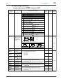
Hardware Specifications
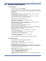
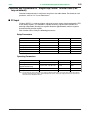
PV Input Signals
• Number of inputs: 1 (terminals
11 - 12 - 13 )
• Input type: Universal input system. The input type can be selected with the software.
• Sampling period: 50, 100, 200 and 500 ms (The sampling period can be selected with
the software.)
Initial value; 200 ms
• Burnout detection: Functions at TC, RTD, standard signal (0.4 to 2 V or 1 to 5 V)
Upscale, downscale, and off can be specified.
For standard signal, burnout is determined to have occurred if it is 0.1 V or less.
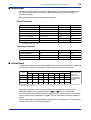
• Input bias current: 0.05 A (for TC or RTD b-terminal)
• Measurement current (RTD): About 0.13 mA
• Input resistance: 1 M or more for thermocouple or mV input
About 1 M for DC voltage input
• Allowable signal source resistance: 250 or less for thermocouple or mV input
Effects of signal source resistance: 0.1 V/ or less
2 k or less for DC voltage input
Effects of signal source resistance: About 0.01%/100 • Allowable wiring resistance: for RTD input
Maximum 150 /wire: Conductor resistance between three wires should be equal
However, 10 /wire for a maximum range of -150.0 to 150.0C.
Wire resistance effect: 0.1C/10 • Allowable input voltage: 10 V DC for thermocouple, mV, or RTD input
20 V DC for DC voltage input
• Noise rejection ratio: 40 dB (50/60 Hz) or more in normal mode
120 dB (50/60 Hz) or more in common mode
• Reference junction compensation error: 1.0C (15 to 35C)
1.5C (0 to 15C, 35 to 50C)
• Applicable standards: JIS, IEC, DIN (ITS-90) for thermocouples and RTD
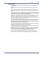
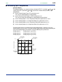
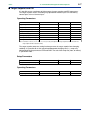
Remote Input Signals
Available only for controllers with remote input terminals.
• Number of inputs: 1 (terminals
21 - 22 )
• Input type: Settable in a range of 0-2, 0-10, 0.4-2.0, or 1-5 V DC
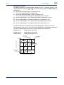
• Sampling period: 100, 200 and 500 ms
The sampling period of a remote input signal is associated with the PV input’s sampling period. If the PV input’s sampling period is 50 ms, however, the sampling period
of a remote input signal lengthens to 100 ms.
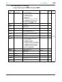
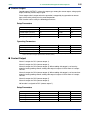
• Input resistance: About 1 M
• Input accuracy: 0.3% 1 digit of input span for 0 to 2 V DC
0.2% 1 digit of input span for 0 to 10 V DC
0.375% 1 digit of input span for 0.4 to 2.0 V DC
0.3% 1 digit of input span for 1 to 5 V DC
Under standard operating conditions (232C, 5510% RH, power frequency of 50/
60 Hz)
IM 05D01B02-41E
1st Edition : May 31,2000-00