1
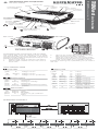
Display Power LED Battery LED Unlocking button for humidifier Heating button OK button Touch wheel with cursor buttons esc button Alarm button Handle Contact sockets for humidifier ON/OFF button Oxygen sensor cable connection Oxygen connection Control tube connection Oxygen output Pressure measuring tube connection brief instructions Connection for tube system/ humidifier TRENDvent Quality makes the Difference for patients as of device software 1.300 This document does not replace the manufacturer's user's manual. Follow the user's manual. Main switch DC Mains socket 24V~/5A Air inlet with integrated filter cassette (fine and coarse filter), detachable CHANGING AND CLEANING THE FILTERS The coarse filter must be cleaned once a week. The white fine filter cannot be cleaned. It should be inspected visually weekly and replaced monthly or more frequently if heavily soiled. 1. Pull the cover of the air inlet from the device. 2. Slide the filter cassette out from the cover of the air inlet. 3. Remove the coarse filter (black) and the fine filter (white) from the filter cassette. 4. Clean the coarse filter with mild soapy water, afterwards rinse the filter thoroughly with clear water. Let the filter dry completely in the air. Instead of cleaning the coarse filter, you can insert a new one. LEDs AND BUTTONS Power LED Color green red none Battery LED Condition lit flashing off Power supply Voltage > 22.0 V Voltage > 22.0 V Voltage > 22.0 V (confirmed) Heating button Color Condition Status green lit Heating on green flashing Heating on standby white lit Heating off white flashing Heating deactivated by battery operation Color Condition Device Capacity green lit on > 80 % yellow lit on > 30 % red lit on < 30 % red flashing on Battery error green flashing off > 80 % (Battery charging) yellow flashing off > 30 % (Battery charging) red flashing off < 30 % (Battery charging) yellow lit off Battery charging error (capacity < 80 %) red lit off Battery charging error (capacity < 30 %) Alarm button Color Condition Priority red flashing HIGH yellow flashing MEDIUM yellow lit LOW or not yet confirmed alarm OPERATING CONCEPT Curve screen Patient screen or on alarm or to last active screen Ventilation sets Comfort screen Alarm screen Counter screen Service screen Status screen MOST IMPORTANT OPERATIONS Action Execution Start ventilation press Stop ventilation press Switch humidifier heating on and off press , confirm query with “Yes” (press Activate the safety lock press => , then press => Deactivate the safety lock => , then press => Switch from curve screen to patient screen Activate other ventilation set press and confirm with ) press Select desired ventilation set with or touch wheel and press Supressing the alarm sound for 2 min or , then select “ Activate changes“ with to confirm press MEANING OF SYMBOLS IN THE SYMBOL AREA OF THE DISPLAY Symbol Meaning Capacity of internal battery Device is set for operation with valve tube system Device is set for operation with leakage tube system Alarm sound was muted Safety lock active Safety lock inactive Device must be serviced Mask test active Softstart ramp active Trigger initiated through patient’s spontaneous respiration Trigger Lock active IMPORTANT ALARMS AND MESSAGES Alarm / message Pressure too high Priority HIGH Pressure too low HIGH Frequency too high HIGH Apnea HIGH Leakage Volume too high HIGH HIGH Volume too low HIGH Oxygen too high Oxygen too low Min. Volume not reached MEDIUM MEDIUM Note Safety Mode active Message Priority Incorrect Tube HIGH System Check HIGH Measuring Tube Internal Battery empty HIGH Check Expiration Valve HIGH Battery Operation Error int. Battery Int. Battery low Calibrate O2 Sensor --- Cause Pressure deviation (IPAP or PEEP) greater than set “Pressure Diff.” Pressure deviation (IPAP or PEEP) lower than set “Pressure Diff.” Measured frequency greater than “Max. Frequency” Set “Apnea Time” exceeded Leakage greater than set “Leakage” or > 2.5 l Measured tidal volume greater than “Max. Volume” Measured tidal volume smaller than “Min. Volume” Measured FiO2 greater than set “Max. Oxygen” Measured FiO2 lower than set “Min. Oxygen” Measured tidal volume smaller than set minimum volume “Vt min” for 3 breaths consecutively Patient not breathing spontaneously Cause Leckage tube system is connected, but a valve tube system is set Pressure difference between measured IPAP and PEEP smaller than the half of pressure difference between set IPAP and PEEP Battery empty Rebreathing volume > 50 % of the inspiration volume (in CPAP mode 70 %) Calculated mask pressure smaller than measured pressure at the air outlet + 1.5 hPa for 3 breaths consecutively MEDIUM Device is not connected to mains power and is being supplied with power by the internal battery MEDIUM Battery defective MEDIUM Battery capacity 10 % Oxygen sensor plugged in after LOW device was turned on Remedy Change setting of tube system on rear of device or replace tube system Check connection between measuring tube and device Battery must be charged; 1 minute until the power supply fails completely; ventilation only possible with external power supply Check expiration valve and replace if necessary or Change setting of tube system on rear of device replace tube system or Connect the control tube to the device Press alarm button Device must be serviced Battery must be charged Calibrate oxygen sensor with ventilation switched off HOFFRICHTER GmbH · Mettenheimer Strasse 12 / 14 · 19061 Schwerin · Germany Tel.: +49 385 39925 - 0 · Fax: +49 385 39925 - 25 · E-mail: [email protected] · Web: www.hoffrichter.de TRENDvent Patient Kurz ENG_2015-03-20_03, Art. No.: 5000 0405