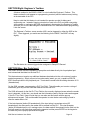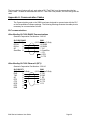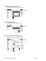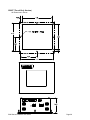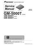
1
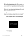
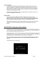
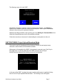
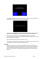
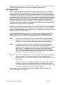
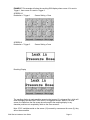
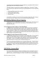
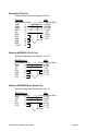
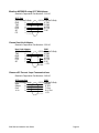
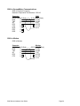
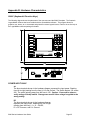
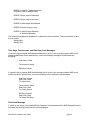
Quartech Corporation
5000 Hardware Users Guide
5000C & 5000T
Quartech Corporation
50680 Corporate Drive
Shelby Township, Michigan USA
48315-3107
Tel: (810) 997-9400
Fax: (810) 997-9407
Email: [email protected]
Web Address: www.quartechcorp.com
5000-HM
Rev:1 6/98
The product described in this document can have a variety of uses, the user and those responsible for applying
this equipment must satisfy themselves as to the acceptability of each application and the use of the unit. Under
no circumstances will QUARTECH CORPORATION be responsible or liable for any damage, including indirect
or consequential losses resulting from the use, misuse, or application of the unit.
The text, illustrations, charts, and examples included in this document are intended solely to help explain
applications of the product. Due to the many variables associated with specific uses or applications,
QUARTECH CORPORATION cannot assume responsibility or liability for actual use based upon the data
provided in this document.
No patent liability is assumed by QUARTECH CORPORATION with respect to the use of circuits, information,
equipment, or software described in this document.
No part of this document may be reproduced, stored in a retrieval system, transmitted in any form or by any
means, including electronic, mechanical, photocopying or otherwise, without the prior express written
permission of QUARTECH CORPORATION.
This document is printed in the U.S.A. and is subject to change without notice.
1997,8 QUARTECH CORPORATION, ALL RIGHTS RESERVED
Quartech Corporation
50680 Corporate Drive
Shelby Twp, MI 48315
Technical Assistance: (810) 997-9400
Fax: (810) 997-9407
BBS: (810) 997-9408
Email: [email protected]
Web: www.quartechcorp.com
5000 Series Hardware User Guide
Page 1
Table Of Contents
SECTION ONE: INTRODUCTION .....................................................................................................................5
MANUAL W RITING CONVENTIONS .......................................................................................................................5
PRODUCT OVERVIEW ........................................................................................................................................6
INTERFACE NOTE .............................................................................................................................................6
SECTION TWO: CONFIGURATION DOWNLOAD MODE.................................................................................6
SECTION THREE: PROJECT UPLOAD/DOWNLOAD MODE ..........................................................................7
RUN MODE ......................................................................................................................................................8
SECTION THREE: DIALOG FILE FORMAT......................................................................................................9
SECTION FOUR: USER SCREEN TRIGGERING .............................................................................................9
5000 TRIGGER W ORD(S) ................................................................................................................................10
SECTION FIVE: METHODS OF SCREEN TRIGGERING................................................................................12
SCREEN TRIGGERING VIA PLC LADDER OR DIRECT DATA W RITES.......................................................................12
SCREEN TRIGGERING VIA THE PUSHBUTTON FIELD OR USER KEY ........................................................................12
SECTION SIX: COMMAND WORD .................................................................................................................12
SOFT LOCKS BITS 0, 1, 2 (16, 15, 14) .............................................................................................................13
Lock Edit Keys Bit 0 (Bit 16)...................................................................................................................13
Lock User Keys Bit 1 (Bit 15)..................................................................................................................13
Lock Touch Screen Bit 2 (Bit 14)............................................................................................................13
ALARM LOG BITS 3, 4, 5, 6(13, 12, 11, 10) ......................................................................................................14
Alarm Log Empty Bit 3 (Bit 13)...............................................................................................................14
Alarm Log Full Bit 4 (Bit 12) ...................................................................................................................14
Print Alarm Log Bit 5 (Bit 11)..................................................................................................................14
Clear Alarm Log Bit 6 (Bit 10).................................................................................................................14
STACK SCREEN BITS 7, 8, 9, 10, 11 (BITS 9, 8, 7, 6, 5) ....................................................................................14
Display Stack Screen Bit 7 (Bit 9) ..........................................................................................................14
Stack Request Bit 8 (Bit 8)......................................................................................................................15
Stack is Empty Bit 9 (Bit 7).....................................................................................................................15
Stack is Full Bit 10 (Bit 6) .......................................................................................................................15
Clear Stack Bit 11 (Bit 5).........................................................................................................................15
VALUE MODIFIED BIT 12 (BIT 4).......................................................................................................................15
PRINT IN PROGRESS BIT 13 (BIT 3) ..................................................................................................................15
5000 POWER UP (BIT 14/BIT 2).......................................................................................................................15
COMMUNICATION ACTIVE FLAG BIT 15 (BIT 1 ) ..................................................................................................16
SECTION SEVEN: KEY DEFINITIONS ...........................................................................................................16
ARROW KEYS.................................................................................................................................................16
ENTER KEY..................................................................................................................................................16
ESCAPE KEY ..................................................................................................................................................16
CLEAR KEY ....................................................................................................................................................16
i AND − KEYS (BRIGHTNESS AND CONTRAST ADJUSTMENT) ..............................................................................17
EIGHT USER KEYS ..........................................................................................................................................17
Switch Image...........................................................................................................................................17
PLC Bit Address......................................................................................................................................17
Bit Status.................................................................................................................................................17
Screen Trigger ........................................................................................................................................17
LOCK KEY......................................................................................................................................................17
POP-UP ALPHANUMERIC KEYPAD .....................................................................................................................18
SECTION NINE: BAR CODE INPUT ...............................................................................................................19
5000 Series Hardware User Guide
Page 2
APPENDIX A: COMMUNICATION CABLES...................................................................................................20
PLC COMMUNICATIONS ...................................................................................................................................20
ALLEN-BRADLEY SLC-500 DH485 COMMUNICATIONS .......................................................................................20
ALLEN-BRADLEY SLC-500 CHANNEL 0 (DF1)...................................................................................................20
ALLEN-BRADLEY PLC-5 CHANNEL 0 (DF1).......................................................................................................21
ALLEN-BRADLEY MICROLOGIX .........................................................................................................................21
GE FANUC SERIES 90 SNP COMMUNICATION ...................................................................................................21
MITSUBISHI FX SERIES ...................................................................................................................................22
MODICON MODBUS 9-PIN D-SUB ..................................................................................................................22
MODICON MODBUS MICRO PHONE PLUG........................................................................................................22
MODICON MODBUS USING 8517 MULTIPLEXER ...............................................................................................23
OMRON HOST LINK ADAPTER ..........................................................................................................................23
SIEMENS S5 CURRENT LOOP COMMUNICATIONS ...............................................................................................23
5000 TO SCREENMAKER COMMUNICATIONS .....................................................................................................24
5000 TO MODEM ............................................................................................................................................24
APPENDIX B: HARDWARE CHARACTERISTICS..........................................................................................25
5000 (KEYBOARD & FUNCTION KEYS) ..............................................................................................................25
POWER INPUT 5000 ...................................................................................................................................25
5000T (TOUCH ONLY) ....................................................................................................................................26
THE FOLLOWING DIAGRAM SHOWS THE PLACEMENT OF THE CONNECTORS AND THE 5000T FACEPLATE....................26
COM1 SERIAL COMMUNICATION PORT ...................................................................................................27
COM2 SERIAL COMMUNICATION PORT ...................................................................................................27
COM3 COMMUNICATION PORT.................................................................................................................27
FUSE ACCESS ................................................................................................................................................27
DIP SWITCH BANK ..........................................................................................................................................27
Dip Switch 1 Download Communication Interface......................................................................................27
Dip Switch 2..............................................................................................................................................27
Dip Switches 3 & 4....................................................................................................................................27
APPENDIX C: ERROR & STATUS CODES ....................................................................................................27
STARTUP MESSAGE ........................................................................................................................................28
PLC COMM MESSAGE ....................................................................................................................................28
SCREENMAKER COMMUNICATION INITIALIZATION MESSAGES ..............................................................................28
SCREENMAKER COMM MESSAGES AFTER COMM ESTABLISHED ..........................................................................28
SCREENMAKER COMMUNICATION FAULT MESSAGES..........................................................................................29
SCREEN STORAGE FAULTS..............................................................................................................................29
DATA ENTRY MESSAGES .................................................................................................................................29
USER KEYS, TOUCHSCREEN, AND EDIT KEYS LOCK MESSAGES ..........................................................................30
FIELD LOCK MESSAGE ....................................................................................................................................30
GLOBAL LOCK/UNLOCK W INDOW .....................................................................................................................31
BRIGHTNESS/CONTRAST ADJUSTMENT W INDOW ...............................................................................................31
GENERAL FATAL ERROR MESSAGES (Q5000 STOPS RUNNING):..........................................................................31
MISCELLANEOUS SCREEN MESSAGES ..............................................................................................................32
PLC SPECIFIC ERROR MESSAGES..............................................................................................................32
ALLEN-BRADLEY SLC-500 DH485 ..................................................................................................................32
Cable Disconnect/Wiring problems............................................................................................................32
Dialog File Error/Duplicate Node ...............................................................................................................32
SLC-500 DH485 Comm Parameters Message ..........................................................................................32
ALLEN-BRADLEY SLC-500 DF1 CHANNEL 0 PORT ............................................................................................33
Cable Disconnect/Wiring problems............................................................................................................33
Dialog File Error........................................................................................................................................33
SLC-500 DF1 Channel 0 Comm Parameters Message...........................................................................33
MODICON MODBUS PROTOCOL .....................................................................................................................33
Cable Disconnect/Wiring problems............................................................................................................33
Dialog File Error........................................................................................................................................33
Modicon Comm Parameters Message.......................................................................................................34
PLC Not Supported...................................................................................................................................34
5000 Series Hardware User Guide
Page 3
APPENDIX D: INSTALLATION .......................................................................................................................34
ELECTRICAL REQUIREMENTS ...........................................................................................................................34
ENVIRONMENT: ..............................................................................................................................................34
WIRING CONSIDERATIONS ..........................................................................................................................34
APPENDIX E: LADDER LOGIC EXAMPLES ..................................................................................................34
TRIGGERING A SCREEN ...................................................................................................................................35
VALUE MODIFIED ............................................................................................................................................35
COMMUNICATION ACTIVE FLAG ........................................................................................................................36
MECHANICAL DIMENSIONS .........................................................................................................................37
5000 (KEYPAD & FUNCTION KEY VERSION) ......................................................................................................37
5000T (TOUCH ONLY VERSION) ......................................................................................................................38
5000 Series Hardware User Guide
Page 4
Section One: Introduction
The Model 5000C combines the functionality of a Graphics Touch Screen and operator
entry device into a single Operator Interface Terminal. Whereas the 5000T (touch only)
has only the touch screen for user entry. Both models of the 5000 series are designed to
communicate directly with various Programmable Controllers. The 5000 communicates
directly to the processor through the programming port eliminating the need for additional
communication interface modules.
Once communication has been established the 5000 can access Word(s), Internal Bit(s),
Counter(s), Timer(s), and Double Word(s), internal to the Programmable Controller.
Access to External I/O and certain restricted areas is also allowed, however, modification
is not possible. The 5000 can access only those file words that exist within the PLC to
which it is connected unless attached to a network.
Manual Writing Conventions
The 5000C has a 5.6” diagonal color touch screen, eight user keys with red LEDs, and a
full numeric keypad. The 5000T has a 5.6” diagonal color touch screen. At times the term
5000 will refer to both versions of the unit. Throughout this manual many references will
be made to these entities, therefore, the following conventions have been established:
‚
If the entire display window is shown, it will appear as a rectangular box with
the characters displayed in the relative position in which they would appear.
Example of entire display window:
Labels that refer to any of the keys on the 5000 will be shown in bold print
and always in capital letters.
Example:
SELECT or ENTER
5000 Series Hardware User Guide
Page 5
Product Overview
The 5000 is customized for a particular application by creating screens. A screen can
contain text, graphics, and bitmaps, and may include variable information from the PLC.
These variables may be modified through the 5000's keyboard or via the pop-up keypad.
Both the PLC and the 5000 can trigger a screen. The section entitled Screen Triggering
will describe screen triggering in detail.
A screen may use all or only part of the 5.6” diagonal display. This allows more than one
screen to be displayed simultaneously.
Interface Note
Please note that both the 5000C and 5000T are shipped from the factory with the
manufacturing test code loaded into its memory. Prior to loading a Project (screens) into
the unit, please refer to SECTION TWO: Configuration Download Mode regarding loading
the communication interface (AB, Modicon, GE, etc.) into the 5000C and 5000T.
Once having downloaded the communication interface of your choice; return to SECTION
THREE in order to better understand the mechanics of downloading/uploading your
projects.
SECTION TWO: Configuration Download Mode
As stated above both units are shipped from the factory with test code used by manufacturing.
You must next load a communication interface, i.e. Allen-Bradley PLC5, Modicon Modbus, etc.
prior to loading your project (screens) in to the unit.
By placing Dip Switch 1in the OFF position (down), both units will be placed into Configuration
Download Mode when power is applied. The connection between the 5000C & 5000T and the
personal computer is via Quartech cable 2126-10 (pin out is on page 24).
The communications interfaces are stored in the ScreenMaker 5000 programming software.
Instructions for the download are shown on the screen of the 5000C & 5000T and in the
software.
The following screen is for the 5000C:
5000 Series Hardware User Guide
Page 6
The following screen is for the 5000T:
Select PC to download via a direct connect to the personal computer. Use Modem to
download via a modem connection to the personal computer. Both require ScreenMaker
software to be running on the personal computer.
With both the 5000 and 5000T, make sure they are in the Waiting for Command Mode, then
initiate the Upload/Download from the ScreenMaker software.
Follow the instruction on the screen for downloading the configuration into the unit.
SECTION THREE: Project Upload/Download Mode
This mode is used for Uploading and Downloading of Screen files and project setup
information created within the ScreenMaker software.
When power is first applied to the 5000C, the keyboard is scanned to see if the 3 key is
being held down. If it is being held down the 5000C will enter into its Project
Upload/Download Mode and the following screen will be displayed.
In the case of the 5000T, touching the screen anywhere while power is applied will bring
the unit into its Project Upload/Download Mode. The following screen will appear:
5000 Series Hardware User Guide
Page 7
If an Upload or Download is desired for local connections press the 1 key for a 5000C unit
or press PC for a 5000T and the unit will display the following:
If you intend on using a Modem for remote uploading and downloading press the 2 key for
a 5000C unit or press Modem for a 5000T and follow the instruction on the screens.
Once the 5000 is setup into its Project Upload/Download Mode for either modem
communication or direct connection, the ScreenMaker programming software can proceed
with the Upload/Download process.
Upon completion of screen transfer, power must be cycled.
If file loading is not desired, simply recycle power on the 5000C and do not press the 3 key
or recycle power on the 5000T while not touching the screen.
Run Mode
If the 3 key is not held down on Power Up the 5000C or the screen on the 5000T is not
touched during power up, the unit will enter Run Mode. The first task is to display a series
of three informational screens which indicate the Part ID number, target PLC, software
version, and serial number. The following are representations of each screen that will be
displayed:
5000 Series Hardware User Guide
Page 8
Calculating Code Checksum…
Quartech 5000(X)
PLC Interface
Software Version: X.XX
Serial Number: XXXXXXX
Initiating PLC Communications
During the above three-screen display, the 5000 will attempt to communicate to the PLC. If
successful the 5000 will proceed by triggering the lowest screen number contained in its
memory. If the 5000 is not successful in establishing communication an error message will
be displayed. Refer to the error code section of this manual for descriptions of errors.
The 5000 will continuously attempt to communicate with the processor. If it gains
communication the PLC, the 5000 will proceed into normal operations. If not, action must
be taken to solve the communication problem.
SECTION Three: Dialog File Format
The Dialog File for the 5000 is the brain center for the interaction between the 5000 and
the PLC. Although the 5000 can access data from any location inside the PLC, it is through
the dialog file; the PLC can force the 5000 to a particular screen, where LEDs can be
turned on by the PLC, and where the 5000 can inform the PLC what items are locked on
its display.
The Dialog File is composed of two unique groups of consecutive registers:
Register
Command Register
Green LED Image
Amber LED Image
Red LED Images
Switch Image
Notes
1 word (16 bits)
1 word (16 bits – Future Use)
1 word (16 bits – Future Use)
1 word (16 bits)
1 word (16 bits)
Register
Integer Triggers
Clock & Calendar
Notes
4 words
3 words
Refer to the ScreenMaker on-line help or ScreenMaker User’s Guide for additional
information on the Dialog File broken down by specific PLC type.
SECTION Four: User Screen Triggering
After communications with the PLC has been established, the 5000 will trigger the lowest
screen in its memory. From this point on screen triggering is then left up to the application
program or the 5000. This section will describe the Trigger word(s) and all of the different
5000 Series Hardware User Guide
Page 9
ways that screens can be sent to the 5000 display. Please note, for additional information
on Alarm Screen Management refer to the ScreenMaker User’s Guide.
5000 Trigger Word(s)
Screen Triggering is the means by which a screen is made to open or close. Ultimately
every screen sent to the 5000 display will channel through a Trigger Word. The 5000's
Trigger Words are configured using the ScreenMaker software. The reference specified in
the "Quartech 5000 Properties" will be Trigger 1. The next three consecutive word address
will be used as Trigger 2, through Trigger 4. Each Trigger word is independent and all four
Trigger Words can be used simultaneously. The use of four Triggers is significant because
it gives the programmer the ability to create a "windows" type effect. For example: The
5000's top quadrant of the display could be used to show machine status using Trigger 1.
Trigger 2 could be used to send fault messages to another quadrant of the display, which
makes the two functions completely independent.
However, when using more than one trigger word, care and planning is critical for success.
Screen settings are important when more than one screen trigger is used because the
settings can greatly affect the overall appearance of the 5000 display when more than one
trigger contains valid screen numbers.
If the application is designed to use only one Trigger Word then simply set each screen
open options to Clear. If the application is more complex and will be designed to use
multiple Trigger Words, the setting of the screen open option becomes very important.
Clear:
If the screen is configured for clear, the entire 5000 display will be cleared
before this screen is displayed. This allows only one screen to appear on the
display even if another screen was previously opened in another trigger.
Cover:
If a screen is configured for cover, the 5000 will not be cleared before the
screen is displayed. If the screen does not use the entire display, then
characters from a screen that may reside in the other Trigger Word will remain
on the display. This allows a windows type effect to exist on the display.
However, any PLC variable fields that show through from the other Trigger
Word cannot be accessed using the touch screen or keypad. Only those PLC
variable fields on the cover screen can be accessed.
Overlay:
If the screen is configured for overlay, the 5000 will not be cleared before the
screen is displayed. If the screen does not use the entire display, then
characters from a screen that may reside in the other Trigger Word will remain
on the display.
This, similar to the cover configuration, allows windows type effect to exist on
the display. However, the difference between cover and overlay is that any
PLC variable fields that completely show through from the other Trigger Word
can also be accessed using the touch screen or keypad.
The following example will illustrate what the 5000 display would look like when two
screens are triggered to the display.
5000 Series Hardware User Guide
Page 10
EXAMPLE :This example will show the resulting 5000 display when screen 12 is sent to
Trigger 1, then screen 6 is sent to Trigger 2.
SCREEN 12
Destination = Trigger 1
Screen Setting = Clear
SCREEN 6
Destination = Trigger 2
Screen Setting =Cover
Resulting Display
The resulting display is made possible assuming that screen 12 is triggered first, which will
clear the display and add itself. Then screen 6 is triggered second. Since it is a cover
screen, the fields from the first screen show through to the resulting display in any
character positions not occupied by fields on the cover screen 6.
Note: If PLC variables reside on the screen (12) covered by a screen set for cover (6), they
will not be accessible.
5000 Series Hardware User Guide
Page 11
If you desire to have access to both screens simultaneously, regardless of which screen is
atop the other then set the attribute to Overlay.
This feature allows for several different solutions for applications. Since the 5.6” display
can be broken up into independent sections, the following applications could be supported
easily:
•
•
•
•
Monitoring different aspects of the machine
Context Sensitive help screens
Pop-Up step by step instructions
Status windows
The capability of overlaying screens does require preparation when being used. However,
when used creatively, overlays can provide an operator friendly 5000 interface.
SECTION Five: Methods of Screen Triggering
Triggering screens to the 5000 display can be done two different ways. The choice is up to
the programmer. These methods can be used solely or in any combination to create
applications with ease.
Screen Triggering via PLC Ladder or Direct Data Writes
As explained in the previous section of this manual, Screens will always be channeled to
the 5000 through a Trigger Word address within the PLC. Therefore, PLC Ladder Logic
can be setup to monitor what screen is currently displayed and change the screen based
on logic conditions. In addition, a PLC Data Field could be created to write directly to the
Integer Trigger. Once the operator has entered the new value into the PLC Data Field, the
5000 will trigger the corresponding screen.
Screen Triggering via the Pushbutton Field or User Key
The Pushbutton Field/User Key can be setup as a screen trigger button. As each screen is
created in the ScreenMaker software a screen value can be attached to a pushbutton
field/User Key. Any of the four triggers can be assigned a screen number associated with
the Field/Key. If entry is not allowed, the 5000 will simply ignore it when pressed. A zero
assigned will clear the screen from the corresponding trigger word.
The user key attributes are definable on every Cover and Clear screen. Therefore a user
key on one screen could be used as a screen trigger whereas on another screen it could
be a jog button. Keep in mind that a screen open options set to Overlay will not allow user
key definitions. Therefore, the 5000 will default the user key assignments to the screen
being covered.
SECTION Six: Command Word
The Command Word reference is viewed by the 5000 as sixteen individual bits internal to
the host device. The individual bits in the Command Word instruct the 5000 to perform a
specific function, or indicate the status of a function. The 5000 will monitor and update the
5000 Series Hardware User Guide
Page 12
Command Word frequently, so the PLC application program may change each of the bits
at any time. The Command Word is configured/assigned in the "Setup" section of the
ScreenMaker software. Refer to the ScreenMaker User’s Guide or on-line help for
additional information on your specific PLC type.
Bit Reference
Corresponding Function
Bit 00 (Bit 16)
Lock Edit Keys
Bit 01 (Bit 15)
Lock User Keys
Bit 02 (Bit 14)
Lock Touch Screen
Bit 03 (Bit 13)
Alarm Log Empty
Bit 04 (Bit 12)
Alarm Log Full
Bit 05 (Bit 11)
Print Alarm Log
Bit 06 (Bit 10)
Clear Alarm Log
Bit 07 (Bit 09)
Display Stack Screen
Bit 08 (Bit 08)
Stack Request
Bit 09 (Bit 07)
Stack is Empty
Bit 10 (Bit 06)
Stack is Full
Bit 11 (Bit 05)
Clear Stack
Bit 12 (Bit 04)
Value Modified
Bit 13 (Bit 03)
Print in Progress
Bit 14 (Bit 02)
Power Up
Bit 15 (Bit 01)
Communication Active Flag
(Bit XX) Used for Modicon PLCs Only
Soft Locks Bits 0, 1, 2 (16, 15, 14)
These three bits allow the PLC application program to disable specific 5000 functions as
well as indicate the status of the combination locks from the 5000. The 5000 alters the Soft
Lock bits only when a combination lock has been enabled. When any of the Soft Lock bits
are energized by the PLC, the associated lock is enabled, and will remain enabled until the
Soft Lock bit is de-energized in the PLC application program or via the combination lock
from the 5000.
Lock Edit Keys Bit 0 (Bit 16)
This bit allows the programmer the ability to disable the numeric keypad along with the
LOCK, ESCAPE, CLEAR and ENTER keys. When this bit is energized the 5000 will
ignore any attempt at entry into these keys. When this bit is de-energized the keys will
become operational.
Lock User Keys Bit 1 (Bit 15)
When this bit is energized the 5000 will ignore the eight definable user keys. When this bit
is de-energized normal operation of the user keys resume.
Lock Touch Screen Bit 2 (Bit 14)
When this bit is energized the 5000 will ignore the entire Touch Screen. All user
interactions will be suspended, unless using the cursor control keys, user keys, or numeric
keypad. When this bit is de-energized normal Touch Screen operation will resume.
5000 Series Hardware User Guide
Page 13
Alarm Log Bits 3, 4, 5, 6(13, 12, 11, 10)
These four bits control and monitor the status of the Alarm Log. The Alarm log is capable
of 100 fault messages.
Alarm Log Empty Bit 3 (Bit 13)
Command Word bit 3 (bit 13) is energized by the 5000 any time the Alarm Log does not
contain any messages. This function may be useful in an application program designed to
automatically change a screen on the 5000 if the Alarm Log contains a screen. If the PLC
application program does not use this function it may simply be ignored.
Alarm Log Full Bit 4 (Bit 12)
Since the Alarm Log can only contain 100 screens at any given time, the 5000 has the
capability of notifying the PLC that the Alarm Log is full. The feature is particularly useful
for clearing the Alarm Log or printing the Alarm Log. Since the PLC is aware that the 5000
can no longer accept messages in the Log, action can be taken to clear the log to
accommodate more messages, or to notify the operator by triggering a screen. If the PLC
application program does not use this function it may simply be ignored.
Print Alarm Log Bit 5 (Bit 11)
This function may be useful in an application program designed to automatically print
alarms without human intervention. The Print Alarm Log bit is controlled by the PLC and
can be energized to start the Alarm Log Print function. If the PLC application program
does not use this function it may simply be ignored.
Clear Alarm Log Bit 6 (Bit 10)
This bit can be controlled by the 5000 or the PLC. Once energized, the 5000 will
automatically clear its alarm log. When used in conjunction with the Alarm Log is Full bit, it
is an easy way to assure Alarms are continuing to be placed into the Log. Keep in mind
that once this bit is energized all messages, acknowledged or not, will be removed from
the log. If the PLC application program does not use this function it may simply be
ignored.
Stack Screen Bits 7, 8, 9, 10, 11 (Bits 9, 8, 7, 6, 5)
These four bits control and monitor the status of the Screen Stack. The Screen Stack is
capable of storing100 screens.
Display Stack Screen Bit 7 (Bit 9)
This bit is controlled by both the 5000 and the PLC. Once energized, the 5000 will
automatically trigger the screen stack. If, during ScreenMaker setup, you have designated
a screen for default when the stack is empty, this screen will be triggered if the stack does
not contain any messages. If you have chosen not to have a default screen the following
message will appear:
Stack is Empty
Closing Stack
If any screens have been triggered to the stack, the first screen triggered to the stack will
be displayed.
If the PLC application program does not use this function it may simply be ignored.
5000 Series Hardware User Guide
Page 14
Stack Request Bit 8 (Bit 8)
This bit is controlled by the 5000 and the PLC. If this bit transitions from a 0 to a 1, the
5000 will automatically display the top screen in the stack. For each transition from a 0 to
a 1, the 5000 will “step through” the screens residing in its stack one at a time until the
stack is empty. Keep in mind, that this bit should be used with the display stack screen bit
in order to “open the stack window” prior to stepping through the screens. If the PLC
application program does not use this function it may simply be ignored.
Stack is Empty Bit 9 (Bit 7)
This bit is controlled by the 5000. The 5000 will energize this bit when no screens are
present in its stack. The 5000 will also de-energize this bit once a screen has been
triggered to the stack. If the PLC application program does not use this function it may
simply be ignored.
Stack is Full Bit 10 (Bit 6)
This bit is controlled by the 5000. The 5000 energizes this bit when 100 screens are
present in its stack. The 5000 will also de-energize this bit once the number has dropped
below 100. This bit is quite useful when used in combination with the Clear Stack Bit and
the Display Stack Screen Bit. If the PLC application program does not use this function it
may simply be ignored.
Clear Stack Bit 11 (Bit 5)
This bit is controlled by 5000 and the PLC. If a 0 to 1 transition is detected, the 5000 will
automatically purge all screens from its stack. If the PLC application program does not use
this function it may simply be ignored.
Value Modified Bit 12 (Bit 4)
Command Word bit 12 (bit 4) is energized by the 5000 any time a screen sends data to the
processor. This includes PLC Data fields, PLC Text Fields, Recipe Buttons, and
Pushbutton Fields set as Bit Status or Bit set. The 5000 does not de-energize the bit,
therefore the PLC's application program must de-energize it each time it is set. This
function may be useful in an application program designed to automatically change a
screen on the 5000 upon the user entering data in a particular screen. If the PLC
application program does not use this function it may simply be ignored.
Print in Progress Bit 13 (Bit 3)
Command Word bit 13 (bit 3) is energized by the 5000 any time an alarm screen printed
output or alarm log is sent to the printer port. The 5000 will de-energize this bit once the
output is complete. This function may be useful in an application program designed to
automatically print alarm screens. By monitoring this bit the PLC can determine how fast
to trigger the next alarm. Keep in mind that the 5000 will ignore any commands to use the
printer port while the Print in Progress bit is energized. A print progress can also be
cancelled by clearing this bit. If the PLC application program does not use this function it
may simply be ignored.
5000 Power Up (Bit 14/Bit 2)
Command Word bit 7/bit 9 will be pulsed by the 5000 on Power Up. Since the bit is pulsed
there is no need for the PLC application program to de-energize it. This may be useful if
5000 Series Hardware User Guide
Page 15
used in the application program to trigger some action on Power Up. If the application
program does not use the function it may simply be ignored.
Communication Active Flag Bit 15 (Bit 1 )
This bit is set by the 5000 to verify communications is active. The 5000 does not deenergize this bit so it is up to the PLC to utilize this function in its ladder program. The
communication active flag is very useful to allow the PLC to constantly be aware of the
5000’s status. If the 5000 were to be disconnected from the PLC, either on purpose or by
accident, the PLC could halt operations and place the machine in a “safe state” versus
continuing without an operator interface. If the application program does not use the
function it may simply be ignored.
SECTION Seven: Key Definitions
The 5000C keypad is made up of eight user keys, full numeric keypad, LOCK, ESCAPE,
CLEAR, ENTER, and four ARROW keys which can be used for a variety of different uses.
The following is an explanation of each key:
Arrow Keys
The ARROW keys are used to maneuver focus to any PLC variable fields that may reside
on the display. Focus will be demonstrated on the screen by overlaying a yellow box
around the entire field. Each time the ARROW key is pressed focus will move from one
PLC variable to the next in the order of upper left to lower right, with a wrap around feature.
The LEFT and RIGHT ARROW keys are also used for cursor movement during data entry.
ENTER Key
The ENTER key is used to enter into a field as well as to send a new value to the PLC.
When focus has been passed to a PLC Data field the ENTER key will place a _ under the
most significant digit implying that modification is allowed. After modifying the data, the
ENTER key will send a newly entered value to the PLC providing the entry is valid. If the
operator uses the numeric keypad without first using the ENTER key, the value will be
cleared off the display and the new value will appear as the operator presses the keys.
This is useful for entering data completely different from what is displayed.
If focus has been passed to a Recipe/Pushbutton field pressing the ENTER key will
simulate the Recipe/Pushbutton being pressed via the touchscreen. Releasing the ENTER
key will simulate the release of the Recipe/Pushbutton via the touchscreen.
Escape Key
The ESCAPE key allows for easy exit from an entry field. If the operator has entered into
an access field and does not desire to modify its contents, by simply pressing the ESCAPE
key, he/she can terminate edit mode of the field and return to the normal view of the
screen.
Clear Key
The CLEAR key allows for easy clearing of an entry field. If the operator has entered into
an access field and does not wish to type over the contents, by simply pressing the
CLEAR key, he/she can remove the contents of the field and type in a new value.
5000 Series Hardware User Guide
Page 16
i and − Keys (Brightness and Contrast Adjustment)
With the 5000T the i and − keys serve a dual purpose. Used singularly, the keys function
as normal decimal point and sign. However, when pressed simultaneously, they trigger
the contrast adjustment function.
After pressing the two keys, the 5000C will pop-up a brightness/contrast adjustment
screen. Use the UP/DOWN arrow keys for brightness and the LEFT/RIGHT arrow keys for
contrast. When the desired settings are met, press the ESCAPE key to exit
brightness/contrast adjustment mode.
With the 5000T, press the bottom two cell (corners) to trigger contrast adjustment function.
Adjustment is by holding down the up/down key until the desired level is reached.
Eight User Keys
Each of the eight user key s is configured separately and can be re-defined for each Cover
and Clear screen created in the 5000C. Each key can be configured as Momentary
(Pushbutton) or Maintained (Push On, Push Off). There are four different configurations
that can be made for each key:
Switch Image
When the key is configured as Switch Image it will act as either a momentary or
maintained Pushbutton/Selector Switch. The status of the switch is held in the Dialogue
File. Refer to the Dialogue File section of the ScreenMaker User’s Manual to determine
which bit in the switch image word will be affected.
PLC Bit Address
This configuration allows the programmer to assign a specific bit address to the key. When
the key is actuated the associated bit in the PLC will be toggled. This configuration can be
setup as either Momentary or Maintained.
Bit Status
This configuration has an assigned PLC address for the key. When the key is actuated the
bit(s) chosen in the Mask of the assigned address will be affected. This gives the
programmer the ability to change multiple bits in the PLC by the actuation of one key. This
configuration can be setup as either Momentary or Maintained.
Screen Trigger
In this configuration the key can be configured to change the screen or screens in the
integer trigger(s) (up to 4 screens can be assigned). When the key is pressed the
assigned screen(s) will be sent to the integer word(s). The programmer can use this
function to allow the operator to make a decision and continue on a different screen path
based on the decision.
Lock Key
The LOCK key is used to globally unlock/lock user field entry, touch screen and user key
access. When assigned in the ScreenMaker software, the 15 combination locks can be
applied to any PLC access field. If the LOCK key is pressed, the following message will
appear:
5000 Series Hardware User Guide
Page 17
The operator can use the ARROW key to move the focus off of the Lock icon and onto the
Unlock icon. At this time he/she can enter the four digit code to unlock/lock the specific
field. The numbers listed below the Field Lock Status indicate what lock codes are
enabled. In the example above, no field locks are enabled. An X would appear next to the
number that had a lock enabled.
Pop-Up Alphanumeric Keypad
Both the 5000C & 5000T have the unique capability of entering in and displaying
alphanumeric strings from the PLC. Since the operator must have the capability of
using the entire alphabet to support this function, the 5000 comes with a standard
pop-up keypad.
This feature is only available for PLC Text fields and can be both enabled or
disabled. If the option is checked for using the pop-up keypad, the following
window will be displayed when the operator selects the PLC Text Field for input:
The Operator can either use the ARROW keys for navigational around the keypad, or the
touchscreen. The ESCAPE and ENTER keys on the 5000C serve the same purpose as
the escape and enter keys located on the pop-up keypad. The shift off key will act like a
maintained selector, thus requiring a push-on push-off procedure.
5000 Series Hardware User Guide
Page 18
SECTION Eight: Engineer’s Toolbox
A feature resident to the 5000C & 5000T is a tool called the Engineer’s Toolbox. This
feature makes the unit appear as a programming terminal (without ladder access) looking
at the data table of the PLC.
Keep in mind that this feature is not intended for operator use but for debug and
engineering use. Instead of lugging a terminal out next to the PLC and either connecting
via a network or unplugging the 5000 and plugging in the terminal, the Engineer’s Toolbox
will allow you to view and change the contents of the PLC data table without programming
it into the screen.
The Engineer’s Toolbox, screen number 1000, can be triggered by either the 5000 or the
PLC. Once triggered, you would see the following for the 5000C, the 5000T will vary
slightly:
The Exit button is a screen trigger button assigned in Setup/OIT/General.
SECTION Nine: Bar Code Input
The 5000C & 5000T have the capability to accept bar code data directly into its peripheral port
and to download that data into the host PLC.
This feature does not require any additional hardware be attached to the unit nor does it require
special programming. Simply connect a bar code reader (wand, gun, etc.) capable of RS-232
ASCII communication to the peripheral port. Terminate the reader with the ending character of 03
(Hexadecimal).
On the 5000, program a screen using a PLC Text Field. This will enable you to enter a string of
characters (up to 39) into the 5000 and likewise into the host PLC.
The 5000 will search for the first PLC Text Field on the currently displayed screen when the reader
input is detected. At this time, you should see the information read by the bar code reader appear
in the PLC Text Field. Keep in mind that you can also use this feature with the pop-up
alphanumeric keypad. This would enable the operator to enter the bar code string by hand in
case the reader was to fail.
If the last character (before 03 hexadecimal) of the input string is a carriage return (0D
hexadecimal), the data read by the reader will be entered into the PLC. If the last character
(before 03 hexadecimal) is not a carriage return, the data read will be entered into the field, but the
field will remain in edit mode thus requiring the operator to either press ENTER on the keypad or
the enter key on the pop-up alphanumeric keypad.
5000 Series Hardware User Guide
Page 19
The bar code input feature will only work when a PLC Text Field is on the screen when the bar
code is read. If reader is detected when the PLC Text Field is not present, the 5000 will ignore the
read.
Appendix A: Communication Cables
The Communication ports on the 5000 have been designed to communicate with the PLC
or the ScreenMaker Software package. The following drawings illustrate the cable pinouts
necessary for communications to both.
PLC communications
Allen-Bradley SLC-500 DH485 Communications
Quartech Corporation Part Number: 2145-10
SLC-500 DH485
(8 pos. RJ45)
RxTxB
1
RxTxA
2
SC
7
Send/Rec 5
5000
(15 Pin Female D-Sub)
12 RXDB
13 RXDA
7 SC
8 Send/Rec
1 FG
4 RTS
5 CTS
Allen-Bradley SLC-500 Channel 0 (DF1)
Quartech Corporation Part Number: 2136-10
SLC-500 DF1
(9-Pin Female D-Sub)
RXD
2
TXD
3
SC
5
RTS
7
CTS
8
DCD
1
DTR
4
DSR
6
5000 Series Hardware User Guide
5000
(15 Pin Female D-Sub)
2 TXD
3 RXD
7 SC
4 RTS
5 CTS
1 FG
Page 20
Allen-Bradley PLC-5 Channel 0 (DF1)
Quartech Corporation Part Number: 2139-10
PLC-5 DF1
(25-Pin Male D-Sub)
TXD
2
RXD
3
RTS
4
CTS
5
SC
7
DSR
6
DCD
8
DTR
20
5000
(15 Pin Female D-Sub)
3 RXD
2 TXD
4 RTS
5 CTS
7 SC
1 FG
Allen-Bradley MicroLogix
Quartech Corporation Part Number: 2147
MicroLogix
(9-Pin Male D-Sub)
TXD
2
RXD
3
SC
5
5000
(15 Pin Female D-Sub)
3 RXD
2 TXD
7 SC
4 RTS
5 CTS
1 FG
GE Fanuc Series 90 SNP Communication
Quartech Corporation Part Number: 2150-10
Series 90
(15-Pin Male D-Sub)
FG
1
RDB
11
RDA
10
TERM
9
SDB
13
SDA
12
SC
7
CTSB
8
RTSB
14
CTSA
6
CTSB
15
5000 Series Hardware User Guide
5000
(15 Pin Female D-Sub)
14 SDB
6 SDA
12 RDB
13 RDA
7 SC
4 RTS
5 CTS
Page 21
Mitsubishi FX Series
Quartech Corporation Part Number: 2148-10
FX Series
(25-Pin Male D-Sub)
TxDB
3
TxDA
16
RxDB
2
RxDA
15
SC
9
DSR
4
DCC
7
PWE
21
GND
20
DSR
17
+5VDC
24
5000
(15 Pin Female D-Sub)
12 RxDB
13 RxDA
14 TxDB
6 TxDA
7 SC
4 RTS
5 CTS
1 FG
Modicon MODBUS 9-Pin D-Sub
Quartech Corporation Part Number: 2116-10
MODBUS Port
(9-Pin Male D-Sub)
RXD
2
TXD
3
SC
5
DTR
4
DSR
6
RTS
7
CTS
8
5000
(15 Pin Female D-Sub)
2 TXD
3 RXD
7 SC
4 RTS
5 CTS
1 FG
Modicon MODBUS Micro Phone Plug
Quartech Corporation Part Number: 2151-10
MODBUS Port
(8 pos. RJ45 Plug)
RXD
4
TXD
3
SC
5
RTS
6
CTS
7
5000 Series Hardware User Guide
5000
(15 Pin Female D-Sub)
2 TXD
3 RXD
7 SC
4 RTS
5 CTS
1 FG
Page 22
Modicon MODBUS using 8517 Multiplexer
Quartech Corporation Part Number: 2118-10
8517 Port
(15-Pin Male D-Sub)
RXD
2
TXD
3
CTS
4
RTS
5
SC
7
FG
1
5000
(15 Pin Female D-Sub)
2 TXD
3 RXD
4 RTS
5 CTS
7 SC
Omron Host Link Adapter
Quartech Corporation Part Number: 2132-10
Host Link Adapter
(25-Pin Male D-Sub)
TXD
2
RXD
3
RTS
4
CTS
5
SC
7
5000
(15 Pin Female D-Sub)
3 RXD
2 TXD
4 RTS
5 CTS
5 SC
1 FG
Siemens S5 Current Loop Communications
Quartech Corporation Part Number: 2149-10
S5 Connection
(15-Pin Male D-Sub)
Input
2
Output
6
Com
7
+V In
9
5000 Series Hardware User Guide
5000
(15 Pin Female D-Sub)
14 RXD
6 TXD
7 Com
9 +V Out
1 FG
Page 23
5000 to ScreenMaker Communications
5000 to Personal Computer
Quartech Corporation Part Number: 2126-10
Computer
(9-Pin Female D-Sub)
RXD
2
TXD
3
SC
5
RTS
7
CTS
8
DCD
1
DTR
4
DSR
6
5000
(9 Pin Male D-Sub)
2 TXD
3 RXD
5 SC
8 RTS
7 CTS
9 FG
5000 to Modem
5000 to Modem
Computer
(9-Pin Female D-Sub)
RXD
2
TXD
3
SC
5
RTS
7
CTS
8
5000 Series Hardware User Guide
Modem
(25 Pin Male D-Sub)
2 TXD
3 RXD
7 SC
4 RTS
5 CTS
1 FG
Page 24
Appendix B: Hardware Characteristics
5000C (Keyboard & Function Keys)
The following diagram shows the placement of the connectors and the 5000C faceplate. The Quartech
LegendMaker Software has been installed with the ScreenMaker software. This program allows for
graphics, text, boxes, etc. to be created and printed for custom legend inserts. Refer to the on-line help in
the LegendMaker software package for details.
POWER INPUT 5000C
AC
The three terminals shown in the hardware diagram represent the input power. Reading
from left to right (starting from the fuse) L1 L2 and Ground. The Switch depicts 120 versus
240. The switch pointing away from the fuse is 120. Caution: Care must be taken to
verify setting of the dip switch. Damage can result if either voltage is applied to the
wrong setting.
DC
The three terminals shown in the hardware diagram
represent the input power. Reading from left to right
(starting from the fuse), L1 = 12 – 24VDC,
L2 = DC Common, and L3= Ground.
5000 Series Hardware User Guide
Page 25
5000T (Touch Only)
The following diagram shows the placement of the connectors and the 5000T faceplate.
AC
The four terminals shown in the hardware diagram represent the input power. Reading
from left to right (5000T lying on its face), Ground - L2 - (no connection) - L1.
DC
The four terminals shown in the hardware diagram represent the input power. Reading
from left to right (5000T lying on its face), Ground – DC Common - +12 – 24VDC, no
connection.
---------- AC ----------
5000 Series Hardware User Guide
---------- DC ----------
Page 26
COM1 SERIAL COMMUNICATION PORT
COM1 is the communication port used to interface with the multiple PLCs. The
interconnecting cables are described in Appendix A.
COM2 SERIAL COMMUNICATION PORT
COM2 is the communication port used to interface with the personal computer running
ScreenMaker software. In addition, this is the port for using the bar code reader.
COM3 COMMUNICATION PORT
COM3 is the communication port used to interface with Allen-Bradley HDLC protocols such
as PLC-5.
Fuse Access
The fuse used in the 5000 & 5000T AC versions is a standard 1amp fuse (5mm size,
Littlefuse# 239001). For the 5000 & 5000T DC versions the fuse is 3 amp (5mm size,
Littlefuse# 239003). This is field replaceable by removing the rear cover.
Dip Switch Bank
A series of four dip switches are located on the left side of the 5000 (when device is placed
face down and the rear is facing you) or on the bottom for the 5000T (when looking at the
communication ports).
Dip Switch 1 Download Communication Interface
The dip switch labeled 1 is used for placing the 5000 into load system mode. In order to
download a new operating system to the 5000 this dip switch must be placed on. The
5000 will detect this switch upon power up and place itself into the File Load Mode. See
Section One.
Dip Switch 2
Future Use.
Dip Switches 3 & 4
The dip switches labeled 3 & 4 are used for line termination. When either switch is ON, a
240ohm resistor will be placed in line for the RS485 line. With both switches ON, a 120
ohm resistor is placed in line for the RS485 line. Use these when this device is the last
physical node on a 485 network.
Appendix C: Error & Status Codes
The 5000 will display one of the following messages if it encounters a configuration,
communication, or hardware error it cannot recover from without operator assistance. In
addition, status messages have been included for your reference:
5000 Series Hardware User Guide
Page 27
Startup Message
Quartech 5000C or 5000T
XXXXXXXX PLC Interface
Software Version: ##.##
Serial Number: ##########
PLC Comm Message
Initiating PLC Communications
ScreenMaker Communication Initialization Messages
After holding the number 3 key down during power-up, the 5000 will display the following messages.
--------------------------------Quartech 5000 in
Project Upload / Download Mode
Press '1' for PC Communication
Press '2' for Modem Communication
--------------------------------If the 1 key (PC Communication)is selected, the following will be displayed:
Waiting for Command from PC
If the 2 key (modem communication) is selected, the following will be displayed.
--------------------------------Modem Communication Selected
Press ENTER to Initialize Modem
Initializing Modem...
(Displayed after ENTER pressed)
If not successful in initializing the modem, the following will appear on the bottom of the display:
MODEM COMM FAULT
--------------------------------If successful in initializing the modem, the following will be displayed:
Waiting for Command from Modem
ScreenMaker Comm Messages After Comm Established
These messages occur during normal operation of communication between the ScreenMaker
software and the 5000 hardware:
On-line with ScreenMaker
Clearing Quartech 5000 Memory...
Erasing...
5000 Series Hardware User Guide
Page 28
Downloading...
Reading...
ScreenMaker Communication Fault Messages
If any of these appear, try communication with the ScreenMaker software again. If faults continue
contact Quartech Corporation with both the version of the 5000 (As seen on power-up) and the
version of the ScreenMaker Software (Found under Help…About).
Comm Fault #
PC Communications Terminated
Invalid Command Received
Checksum Error
Screen Storage Faults
If any of these messages are encountered, clear memory on the 5000 and try re-loading the
application.
FATAL ERROR:
Screen Pointer Table Corrupt
Clear Memory and Reload Project
FATAL ERROR:
Memory Full or Fragmented
Clear Memory and Reload Project
FATAL ERROR:
Download Fault
Clear Memory and Reload Project
Data Entry Messages
The following messages indicate an entry has been attempted with improper information. Typically
these messages would occur upon keying in values out of range. One exception is the Invalid Recipe
Write Address. If you encounter this message, correct the Recipe Field in the ScreenMaker Software.
ERROR: Invalid value entered
ERROR: Value less than lower limit
ERROR: Value greater than upper limit
ERROR: Invalid date entered
ERROR: Invalid time entered
5000 Series Hardware User Guide
Page 29
ERROR: Invalid PLC address entered
(Engineer's toolbox address field)
ERROR: Recipe value at maximum
ERROR: Recipe value at minimum
ERROR: Invalid recipe write address
ERROR: Barcode string too long
ERROR: Invalid Protocol Detected
In Received Message
The following messages are displayed if a valid date or time is entered. These are specific to date
and time entry:
Setting Date...
Setting Time...
User Keys, Touchscreen, and Edit Keys Lock Messages
If a specific key is pressed AND the associated lock bit is set in the command register AND a lock
code does NOT exist for the specified key, one of the following messages will be temporarily
displayed:
User Keys Locked
Touchscreen Locked
Edit Keys Locked
If a specific key is pressed AND the associated lock bit is set in the command register AND a lock
code exists for the specified key, one of the following unlock windows will be displayed:
User Keys Locked:
Enter Lock Code
To Unlock Keys
Touchscreen Locked:
Enter Lock Code
To Unlock Screen
Edit Keys Locked:
Enter Lock Code
To Unlock Edit Keys
Field Lock Message
If a field on the screen is activated AND the field has a lock associated with it AND the specific lock is
activated, the following unlock window will be displayed:
5000 Series Hardware User Guide
Page 30
Field Locked:
Enter Lock Code
To Unlock Field
Depending on whether or not a correct lock code was entered on one of the above unlock windows,
one of the following messages will be displayed:
LOCK DISABLED
or
INVALID CODE
Global Lock/Unlock Window
Global Lock/Unlock window allows a user to lock or unlock any of the 15 field locks or any of the
keypad locks. Pressing the LOCK key activates this window. Depending on function selected, and
whether or not a valid code was entered, one of the following messages will be displayed:
LOCK ENABLED,
LOCK DISABLED
or
INVALID CODE
Brightness/Contrast Adjustment Window
5000C
Pressing the • and − key activates the following window:
Use ↑↓ keys to adjust brightness
Use ←→ keys to adjust contrast
brightness = ##% contrast = ##%
5000T
Pressing the lower two cells (corners) at the same time.
General Fatal Error Messages (5000 stops running):
FATAL ERROR ##
Contact Vendor
XXXXXX PLC Interface
Software Version: ##. ##
FATAL ERROR:
Invalid Setup Data
FATAL ERROR:
Invalid Screen # Triggered
Press ENTER to Restart System
FATAL ERROR:
An Alarm Screen Has Triggered
A Non-Existent User Screen
Press ENTER to Restart System
5000 Series Hardware User Guide
Page 31
FATAL ERROR:
No Display Screens in Memory
Miscellaneous Screen Messages
Error: Alarm Screen Cannot be Displayed
(This is triggered if an alarm screen triggers another alarm screen. The second alarm screen is
ignored, but a message is temporarily displayed. Displayed 2-4 seconds.)
No Display Screens Triggered
(Displayed until a display screen is triggered)
Stack is Empty
Closing Stack
(Displayed if a stack empty screen is not specified. Displayed 2-4 seconds.)
PLC Specific Error Messages
The following error messages are broken up by PLC brand in alphabetical order.
Allen-Bradley SLC-500 DH485
The following messages are communication errors and should be addressed through
ScreenMaker/5000 setup, wiring of the network and SLC setup.
Cable Disconnect/Wiring problems
PLC Comm Fault:
Check Cable and PLC
PLC Comm Fault:
Cable Disconnected at Quartech 5000
Dialog File Error/Duplicate Node
If the following messages occur, verify setup the of the dialogue file and node number in both the
ScreenMaker Software and SLC-500 data table setup.
PLC Comm Fault:
Check dialog file number and size
PLC Comm Fault:
Duplicate node on network
SLC-500 DH485 Comm Parameters Message
If any of the previous messages appear, this message will also appear in order to give you a
breakdown of the 5000 setup. This message is extremely useful in order to determine where the
setup problems reside (5000 versus SLC-500).
OIT N = ##, PLC N = ##, Baud = ##
Dialog File = ##, Max Poll = ##
5000 Series Hardware User Guide
Page 32
Allen-Bradley SLC-500 DF1 Channel 0 Port
The following messages are communication errors and should be addressed through
ScreenMaker/5000 setup, wiring, and SLC setup.
Cable Disconnect/Wiring problems
PLC Comm Fault:
Check Cable and PLC
PLC Comm Fault:
Cable Disconnected at Quartech 5000
Dialog File Error
If the following message occurs, verify setup the of the dialogue file in both the ScreenMaker Software
and SLC-500 data table setup.
PLC Comm Fault:
Check dialog file number and size
SLC-500 DF1 Channel 0 Comm Parameters Message
If any of the previous messages appear, this message will also appear in order to give you a
breakdown of the 5000 setup. This message is extremely useful in order to determine where the
setup problems reside (5000 versus SLC-500).
Baud = ##, Dialog File = ##
Modicon MODBUS Protocol
The following messages are communication errors and should be addressed through
ScreenMaker/5000 setup, wiring, and PLC setup.
Cable Disconnect/Wiring problems
PLC Comm Fault:
Check Cable and PLC
PLC Comm Fault:
Clear To Send Input Line False
Dialog File Error
If the following messages occur, verify setup of the dialogue file in both the ScreenMaker Software
and SLC-500 data table setup.
PLC Comm Fault:
Check Dialog File Command Reg. Address
PLC Comm Fault:
Check Dialog File Int Triggers Address
5000 Series Hardware User Guide
Page 33
Modicon Comm Parameters Message
If any of the previous messages appear, this message will also appear in order to give you a
breakdown of the 5000 setup. This message is extremely useful in order to determine where the
setup problems reside (5000 versus Modicon).
PLC Node = ##, Baud = ##
Int Trigger = ##, Command Reg = ##
PLC Not Supported
If you receive this message contact factory for list of PLCs supported.
PLC Comm Fault:
Attached PLC Model is NOT Supported
Appendix D: Installation
The 5000 is designed to be mounted in the door of an enclosure or on an operators
console for ease of use. Care should be taken when drilling and cutting out the mounting
holes for the unit in order to protect it from metal chips and conductive particles. Failure to
protect the unit may cause damage when power is applied and may void warranty.
A minimum clearance of six inches should be kept between the unit and any other device
that generates heat. In the event that the internal enclosure temperature periodically
exceeds 50 degrees Celsius (122 degrees Fahrenheit), fans or a purge air system should
be used to increase the air flow, and eliminate "Hot Spots" that occur within the panel.
Electrical Requirements
120 VAC +/- 10% Fuse at 1 Amp
Environment:
Operating Temperature:................... 0ºc to 55ºc
Storage Temperature....................... -20ºc to 60ºc
Operating Humidity .......................... 20% to 95% (non-condensing)
Wiring Considerations
Care should be taken when routing AC power supply cable and the communication cable.
Follow these guidelines for a trouble free installation.
Communication cable must be kept away from AC power lines. Keep at least
one foot away from 115 VAC lines, and two feet away from higher voltage lines.
If the cable must cross AC power lines, cross them at right angles (90).
Keep the cables away from sources of high energy fields such as arc welders,
AC motors, motor starters, servo controllers, generators, induction heaters, and
transformers.
Appendix E: Ladder Logic Examples
Although minimal ladder logic is required for use with the 5000 operator interface terminal, several
5000 Series Hardware User Guide
Page 34
unique features can be utilized when used in conjunction with ladder.
Triggering a Screen
This example shows the basic circuit for triggering a screen via the PLC. When the trigger circuit
energizes, the value 1000 will be moved into the integer trigger element-causing screen 1000 to
be displayed. In this example, screen 1000 is the Engineer’s Toolbox as described in the
Engineer’s Toolbox section of this manual.
Move Statement
Source = 1000
Destination = Trig 1
Trigger
Circuit
Value Modified
This example would be used to automate screen triggering if a sequence of screens was desired
for your process. This example shows the step through process of screens 10 through 20.
Value
Modified
Source Trig 1
<9
>21
ADD
Source 1 to
Trig 1
Value Modified
Reset (unlatch)
The above example assumes
That screen 10 is being displayed
And that a PLC Access Field is
Modified causing the Value Modified bit to energize.
5000 Series Hardware User Guide
Page 35
Communication Active Flag
This bit will be energized by the 5000 anytime it is found de-energized. The PLC can use this bit
as part of a watchdog timer circuit to detect a loss of communication with the 5000. The following
is a typical circuit used to detect a loss of communication with the 5000.
Communication
Active Flag
Timer on Delay
Timer One = XXX
Time Base = 1.0
Preset = 10
Active Flag
T 2 Done
Timer on Delay
Timer Two = XXX
Time Base = 1.0
Preset = 5
De-energize/Unlatch Communication Active
Flag Bit (Bit 15)
T 1 Done
Create an output for this rung. This output will
be energized if communications is lost.
5000 Series Hardware User Guide
Page 36
Mechanical Dimensions
5000C (Keypad & Function Key Version)
All dimensions in inches.
5000 Series Hardware User Guide
Page 37
5000T (Touch Only Version)
All dimensions in inches.
5000 Series Hardware User Guide
Page 38