1
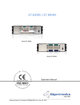
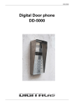
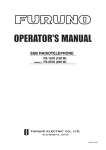
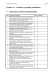
SAFETY INSTRUCTIONS
DANGER
Do not work inside the
equipment unless totally
familiar with electrical
circuits.
Hazardous voltage which
will cause death or serious
injury exists at the
following locations:
• Transceiver unit
• Antenna and antenna
coupler (both at TX)
WARNING
Turn off the power at the
mains switchboard before
beginning at installation.
Post a sign near the switch
to indicate it should not be
turned on while the
equipment is being
installed.
Fire, electrical shock or
serious injury can result if the
power is left on or is applied
while the equipment is being
installed.
Use only the supplied cables.
HAZARDOUS VOLTAGE
is present at these points.
Use of other cables can result in fire or
serious equipment damage.
Use the correct fuse.
Use of wrong fuse can cause fire.
ANTENNA COUPLER
CAUTION
Ground the equipment to
prevent electrical shock and
mutual interference.
When using a copper plate for ground
be careful of its edges.
Edges can cut fingers.
If the distress alert is accidentally
transmitted, transmit appropriate
message to nearest coast station to
cancel the distress alert.
i
Table of Contents
Page
1. Rack Console Chassis (RC-1500-1T) .......................................... 1
2. AC/DC Power Supply and Battery Charger................................. 3
3. Connection .................................................................................... 5
4. Adjustment at Installation ............................................................10
Outline Drawings ............................................................................ D-1
System Diagram ............................................................................. S-1
Schematic Diagram ........................................................................ S-3
ii
1. Rack Console chassis (RC-1500-1T)
General
The RC-1500 series Radio Console comes in five models: RC-15001T-150/250, RC-1500-1T-400/800, RC-1500-1T-2P, and RC-15001T-TOKU.
The type and number of components incorporated differs from model
to model, however each model contains an Inmarsat-C mobile earth
station, NBDP terminal, DSC terminal, DSC watch receiver, and SSB
radiotelephone.
Below are the distinguishing characteristics of each model.
RC-1500-1T-150/250: Incorporates the FS-1562-15/1562-25 SSB
radiotelephone.
RC-1500-1T-400/800: Incorporates the FS-5000/8000 SSB radiotelephone.
RC-1500-1T-2P: Russian model.
RC-1500-2T: Incorporates the FM-8500 VHF radiotelephone.
RC-1500-1T-TOKU: Special order model.
Mounting considerations (tabletop mount)
When selecting a mounting location;
•
Make sure the location is strong enough to support the unit (about
100 kg) under the conditions of continued vibration and shock
normally encountered on the vessel. Where necessary, reinforce
the mounting location by lining block or doubling plate.
•
Locate the unit where it is easily accessible and does not interfere
with personnel or operation of other equipment; for example,
ship’s wheel.
•
Select a location where temperature and humidity are moderate
and stable.
1
Mounting
The mounting dimensions of the RC-1500-1T are as shown in the
figure below. (Refer to the outline drawing attached to the end of this
manual for further details.)
PP-510
Hanger
950
MAX
735
630
Bottom
Cable
Entry
80
Keyboard
530
530
Unit: mm
Rack consaole chassis (Top View)
MIN
270
120
Rear
cable
gland
Unit: mm
Side view
Before mounting the unit, determine location of cable gland. The interconnection cable should be run though either the rear or bottom
side of the rack console chassis. See the outline drawing attached for
further details.
Procedure
1. Place the rack console chassis on the tabletop.
2. Mount three hangers for the DSC-6, AA-50 and FS-1562 as shown
above.
3. Set the DSC-6, AA-50 and FS-1562 (only 150W type or 250W
type) to the hangers with knobs. Set the FM-8500 to the hanger
with knobs (only RC-1500-2T).
4. Mount the two printers PP-510 and printer selector to the top of
the console chassis.
5. Place the NBDP and FS-5000 on the tabletop (only 400W type).
6. Place the Inmarsat C outside of rack console.
2
2. AC/DC Power Supply and Battery Charger
Mounting considerations
The unit can be mounted almost anywhere provided the location satisfies the following requirements.
•
Vibration-free location
•
Well-ventilated area
•
Free of water splash
•
Leave enough space around the sides of the unit to permit maintenance and checking.
•
The mounting location must be able to support the weight of the
unit (PR-850A: 35 kg, PR-300: 14.5 kg, BC-6158/6200: 28 kg,
S-5300A/8300A: 85/110 kg) under the condition of continued
vibration normally encountered aboard the vessel.
Mounting
Refer to the outline drawing attached to the end of this manual for
further details.
• PR-850A
DC IN DC OUT
352
Cable
terminal
6-φ 6
Fixing holes
55
120
440
120
250
Cable
terminal
55
AC IN
370
Front view
Top view
Unit: mm
• PR-300
270
4-φ 6
Fixing holes
233
163
350
230
290
Front view
Top view
Cable terminal
3
• BC-6158/6200
490
360
4-φ 7
Fixing holes
200
510
360
490
Front view
Top view
• S-8300A
2x φ15
Fixing holes
Service space
100
400
Service space
100
Air Vent
875
890
Rear cable
gland
A
Air Vent
850
Air Vent
520
520
Front view
25
4x φ15
Fixing holes
450
Bottom cable
gland
Side view
Unit: mm
TB2
TB1
520
TB3
45
45
80
360
80
View from A
Fasten the S-8300A to the mounting location by fixing four fixing
screws (φ15) at the bottom and two fixing screws (φ15) at the top.
The interconnection cable between the S-8300A and the rack console
chassis should be run through either the bottom or rear side of the S8300A as shown above.
4
3. Connection
The figure belows shows view of rack console chassis. Remove the
cover access terminal boards to make connections.
TB1
TB2
TB3
Front Cover
Screw
Remove cover to access three terminal
boards, TB1, TB2 and TB3.
Remove jumper wires between TB2 and TB3.
TB1
1
......
12
TB2
1 ..... 11 12
See next page.
TB3
1 2 ..... 12
Connect cables to the AC/DC
Power Supply Unit.
5
ACIN 2
ACIN 1
TB1
TB2
(H) 1
(C) 2
1
2
3
4
(+) 24V 5
CHARGE 6
TB3
(H)
(C)
(H)
(C)
Battery
(+) 24V(1)
(-)
DPYC-8
DPYC-3.8
4
1
No.1 MAIN SOURCE
100-120/200-240VAC
1φ, 50/60Hz
DPYC-3.5
DPYC-5.5
DPYC-1.25
DPYC-5.5
1 2 3 4 5 6 7 8 9 10 11 12
EMERGENCYL
CHARGER ONL
(+)
(-) BATT.(1)
(+)
CHARGE(1)
(-)
CHARGER SOURCE
100-120/200-240 VAC
1φ, 50/60Hz
DPYC-38
TB1
TB1
BATT
TB2
DC-OUT
1φ, 50/60Hz
DPYC-3.5
DPYC-5.5
(L)
(N)
F. G.
ALL CABLES SHIPYARD SUPPLY
AC-DC POWER
SUPPLY
PR-300
TB1
1
BATT
2 (-)
TB2
1 (+)
DC-OUT
2 (-)
TB3
1 2 3 4 5 6 7 8 9 10 11 12
AC-DC POWER
No.2 MAIN SOURCE
SUPPLY
100-120/200-240VAC
PR-850A
(L)
(N) AC-IN
F. G.
(-)
(+)
(-)
TB3
AC-FAIL
(+)
....
....
DPYC-5.5
TB3
(+)
24V(2)
(-)
AC/DC POWER SUPPLY TYPE
(+)
6
7
BATTERY
(+)
24V(1)
(-)
EMERGENCYL
CHARGERONL
(+)
BATT(1)
(-)
(+)
CHARGER(1)
(-)
DPYC-38
DPYC-5.5
DPYC-8
(V) MAIN SOURCE
GND
(U)
RADIO (+)
BATT ( - )
TB2 1 2 3
(+)
(-)
AC-FAIL
(+)
(-)
24VDC-OUT
No.1 MAIN SOURCE
100-120/200-240VAC,
1 φ , 50/60Hz
S-5300A/8300A
AC/DC
RADIO
SWITCH BOX
CHARGE
PR-300
AC-DC POWER SUPPLY
(L) (N) F.G
TB3 1 2
TB2 1 2
DPYC-5.5
TB1 1 2 3
DPYC-3.5
DPYC-5.5
TB3 1 2 3 4 5 6 7 8 9 10 11 12
ALL CABLES SHIPYARD SUPPLY
No.2 MAIN SOURCE
100-120/200-240VAC,
1φ, 50/60Hz
TPYC-1.25
TB2 1 2 3 4 5 6 7 8 9 10 11 12 13 14 15 16 17 18 19 20 21 22 23
DPYC-38
TB2 1 2 3 4 5 6 7 8 9 10 11 12
(+)
(-)
BTT
TB1 1 2 3 4 5 6 7 8 9 10 11 12
AC/DC RADIO SWITCH BOX TYPE
(+)
(-)
DC-OUT
Connect cables with connectors in the rack console chassis among
the equipment.
RC-1500-1T-150/250, RC-1500-2T type
TO PRINTER SELECTOR
ANTENNA
PRINTER
OPTION
PRINTER
FOR
POWER
POWER
DC24V
MF-HF RX
DSC-6
MH-HF
RX
NBDP
NMEA
DMC
ANT
DSC
DSC
DC24V
AA-50
FOR
POWER
POWER
MF-HF TR
NMEA IN
CO-2P
(*1)
MF-HF TR
NBDP
MF/HF DSC
TB5
ANT
DISTRIBUTION
PCB (05P0606)
DMC-5
(option)
FOR
POWER
TB6
TB7
TB7
TB7
DC24V
REMOTE B
NMEA
POWER
DP-6
FS-1562
NMEA
REMOTE
REMOTE
POWER
TO-IC-212
(Inmarsat C)
REMOTE B
FOR
POWER
H.P.A
TB3
TB4
REMOTE A
DC24V
REMOTE A
TERMINAL
FOR POWER
IB-581
(*1):Shipyard supply
SERIAL
PRINTER
:Labels on the connectors
from rack console chassis
TO PRINTER SELECTOR
RC-1500-1T-400/800, RC-1500-1T-2P type
TO PRINTER SELECTOR
ANTENNA
PRINTER
OPTION
PRINTER
FOR
POWER
POWER
DC24V
DMC
MF-HF RX
DSC-6
MH-HF
RX
NBDP
NMEA
ANT
DSC
DSC
FOR
POWER
POWER
MF-HF TR
NMEA IN
NMEA
DC24V
AA-50
CO-2P
(*1)
MF-HF TR
NBDP
MF/HF DSC
TB7
TB7
TB7
REMOTE B
REM1
POWER
DC24V
DP-6
REM1
NMEA
NMEA
TO-IC-212
(Inmarsat C)
MAIN
FS-5000C
NMEA
REMOTE B
FOR
POWER
TB7
DISTRIBUTION
PCB (05P0606)
DMC-5
(option)
FOR
POWER
TB6
REM3 POWER
DC24V
REMOTE A
REMOTE A
FOR POWER
TERMINAL
(*1):Shipyard supply
IB-581
SERIAL
PRINTER
TO PRINTER SELECTOR
8
:Labels on the connectors
from rack console chassis
FOR
FS-5000T
IC-302
DISTRESS
ALERT UNIT
TO DISTRIBUTION PCB
DMC
Inmarsat C
TERMINAL UNIT
(IB-581)
DC24V
FOR
POWER
DTE1
SERIAL
NMEA
DMC
REMOTE A
PRINTER
Inmarsat C
COMMUNICATION UNIT
(IC-212)
PRINTER
DC24V
FOR POWER
TO DSC-6
TO DP-5/6
PRINTER
DSC
NBDP
PRINTER SELECTOR
TO
DISTRIBUTOR
FOR
POWER
PP-510
DC24V
PRINTER
FOR
POWER
PP-510
DC24V
PRINTER
PRINTER
Distribution PCB
9V
TB1
POWER CABLE
Printer
Selector
1
GND 2
+9V
TB2
+24V 1
0V 2
FOR POWER
TB6
NMEA-IN-H
1
NMEA-IN-C 2
NMEA IN
C0-0. 2x2P
05P0606
9
4. Adjustment at Installation
1. SSB Radiotelephone
For FS-1562
Register permitted frequency and change system setting if necessary,
referring to the Service Manual SME-5572.
For FS-5000
Register permitted frequency and change system setting if necessary,
referring to the Service Manual SME-5519.
2. DP-6
To change the system setting and conduct self-test, refer to the
Operator’s Manual OME-5610.
3. FELCOM 12
To carry out log-in and set the system setting, refer to Installation
Manual IME-5613 and Operator’s Manual OME-5613.
4. DSC-6
To set the system setting and conduct self-test, refer to the Operator’s
Manual and Installation Manual.
5. PP-510
Set a recording paper and a cartridge and carry out self-test, referring
to Operator’s Manual OME-5080.
6. DMC-5 (option)
To set the system setting, refer to Operator’s Manual OME-5544.
To check the printer selector, transmit data from the DSC-6 and the
NBDP and confirm that it is printed correctly.
10