1
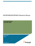
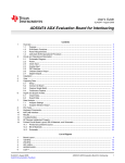
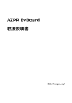
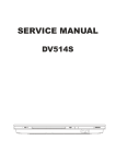
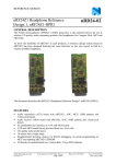
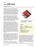
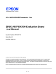
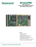
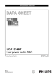
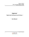
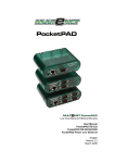
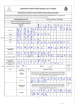
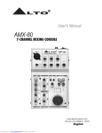
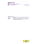
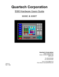
USER MANUAL
nRF24Z1 Evaluation board
1.
nRF24Z1-EVB
General description
This document describes the nRF24Z1-EVBOARD and its use with the Nordic
Semiconductor nRF24Z1 Single Chip 2.4 GHz RF Audio streamer.
Figure 1: The nRF24Z1-EVBOARD
There are two versions of the nRF24Z1-EVBOARD. One is fitted with the nRF24Z1 in audio
receiver (ARX) mode (Figure 1, top) the other with the nRF24Z1 set in audio transmitter
(ATX) mode (Figure 1, bottom). The two boards are also populated differently in the audio
front end section. The reason for the differences will be explained further in the following
sections.
Nordic Semiconductor ASA
Revision: 1.3
-
Vestre Rosten 81, N-7075 Tiller, Norway
Page 1 of 27
-
Phone +47 72 89 89 00
-
Fax +47 72 89 89 89
May 2005
USER MANUAL
nRF24Z1 Evaluation board
2.
Introduction
The Evaluation Board for the nRF24Z1 Single Chip 2.4 GHz RF audio streamer has been
developed to enable customers to test functionality, run communication and verify the
performance parameters of the device. This document describes the usage of the nRF24Z1EVBOARD.
The nRF24Z1-EVBOARD is intended for evaluation and development purposes only. It is
not intended for incorporation into an end product.
3.
Getting started
The nRF24Z1-EVBOARD V1-0 is shipped with an EEPROM programmer and emulator
(programming dongle). The nRF programming dongle enables you to download register
settings and access the control link offered by nRF24Z1.
The following equipment is needed to work efficiently with the nRF24Z1-EVBOARD:
•
•
•
•
•
PC with 1 free USB port
Z1config PC software (supplied)
1 nRF EEPROM programmer and emulator (supplied)
Two 2.0 V - 3.6V or one 4.6 – 12V DC voltage supply
1 male A/B USB cable (supplied)
To evaluate the performance of the device the following instrumentation should be available:
•
•
•
•
Audio source, analog or digital. Analog audio input is AC coupled, with a maximum
swing of 2.6Vpp (0.9Vrms). Minimum input resistance is 10kΩ. Digital audio input is via
S/PDIF RCA phono connector (0.5Vpp,75Ω)
Audio amplifier and loudspeakers. Analog audio out is 2.1Vpp (0.75Vrms) at a load of
5kΩ. Digital audio output is via S/PDIF RCA phono connector (0.5Vpp,75Ω)
Oscilloscope
2.4 GHz Spectrum analyzer
Nordic Semiconductor ASA
Revision: 1.3
-
Vestre Rosten 81, N-7075 Tiller, Norway
Page 2 of 27
-
Phone +47 72 89 89 00
-
Fax +47 72 89 89 89
May 2005
USER MANUAL
nRF24Z1 Evaluation board
4.
Programming dongle description
The programming dongle is fitted ‘on-top’ (Figure 2) of the nRF24Z1-EVBOARD and
controlled through PC software. The Z1config software is documented in Z1config user
manual [1].
The dongle will mainly be fitted on the nRF24Z1 audio transmitter (ATX) board. Through
this interface the user also has full control of the audio receiver board through the control/data
RF link offered by nRF24Z1. The dongle needs to be connected to the audio receiver board
only if default configuration in the audio receiver EEPROM is to be changed.
PC
USB Link
USB
MCU
SPI Link
SPI
MASTER
PLD PROG
OFF/ON
SLAVE
(+4.5 – 12v)
EEP
MUX
Figure 2: nRF24Z1-EVBOARD with programming dongle
4.1. Supply
Main power supply is fed to the nRF programming dongle through the USB interface (J101).
Supply voltage to the nRF24Z1-EVBOARD interface stage runs through J102 from the
nRF24Z1-EVBOARD. The programming dongle must hence be plugged in the EVBOARD
connector JP2 in order to have proper signal levels on J102.
Nordic Semiconductor ASA
Revision: 1.3
-
Vestre Rosten 81, N-7075 Tiller, Norway
Page 3 of 27
-
Phone +47 72 89 89 00
-
Fax +47 72 89 89 89
May 2005
USER MANUAL
nRF24Z1 Evaluation board
4.2. nRF24Z1-EVBOARD interface
The pin-out of the interface (J102) to the nRF24Z1-EVBOARD can be found under the
nRF24Z1-EVBOARD description (EVBOARD connector JP2). The PC interface (J101) is a
standard USB B-connector interface.
4.3.
USB addressing (S101)
The dongle has an option to use 2 different USB addresses set by S101. This option is only
needed if the same USB hub is to interface two dongles. The position of S101 is hence not
important in the nRF24Z1-EVKIT unless you have two audio transmitter boards connected
to the same PC (2 different EVKIT’s) at the same time.
Nordic Semiconductor ASA
Revision: 1.3
-
Vestre Rosten 81, N-7075 Tiller, Norway
Page 4 of 27
-
Phone +47 72 89 89 00
-
Fax +47 72 89 89 89
May 2005
USER MANUAL
nRF24Z1 Evaluation board
5.
nRF24Z1-EVBOARD DESCRIPTION
Figure 3 shows the block diagram of the nRF24Z1-EVBOARD.
Further details can be found in appendix 1 (circuit diagram and PCB layout) and appendix 2
(component list).
SPI
Master
2-wire
Slave
JP4
JP5
6
UART
GPIO
Master Slave
JP6
6
JP7
4
RF I/O
JP3
4
JP8
3
J1
12
JP13
VDDE
PC interface
10
MUX
8
20
nRF24Z1
2
S2
JP2
6
JP10
S101
JP9
S3
EEPROM
JP102
VDDE
S/PDIF
signal
condition
5
2
RESET
4
5
ADC
5
DAC
V-REG
VDDA
JP101
J104
J101
VDD
VDD-nRF VDDA
4.5 - 12 V
J4
JP1
J2
J3
J103
Optional
S/PDIF
I2S
DIGITAL AUDIO I/O
LEFT
RIGHT
ANALOG AUDIO I/O
Figure 3: Block diagram of the nRF24Z1-EVBOARD
Due to the significant difference in functionality when the nRF24Z1 is configured in audio
transmitter mode (found at audio source side like the CD player) and in audio receiver mode
(loud speaker side) the two EVBOARD’s in the EVKIT are preset as audio transmitter and
receiver. The audio section of the two versions of the EVBOARD are populated differently
(S/PDIF and ADC/DAC section), but note that the section around nRF24Z1 (device and
external components) are identical on the two boards.
To enable convenient control of the nRF24Z1-EVBOARD from a computer, a MUX (Altera
PLD) is put on the nRF24Z1-EVBOARD to ease PC interfacing with nRF24Z1 and the on
board EEPROM. The on board mux is hence only for EVBOARD versatility and not needed
in a final design.
5.1.
Supply (J101, J103, J104)
Power supply and ground is fed to the nRF2Z1-EVBOARD either trough on-board voltage
regulators (connector J101) or directly from external supplies (J103, J104). J101 is the
primary VDD to be used with the nRF24Z1-EVBOARD.
If jumper JP101 (leave JP102) are removed, connector J104 supplies, supply to all circuitry
except on the board ADC/DAC. J104 supplies VDDA, analog power for the on board ADC or
Nordic Semiconductor ASA
Revision: 1.3
-
Vestre Rosten 81, N-7075 Tiller, Norway
Page 5 of 27
-
Phone +47 72 89 89 00
-
Fax +47 72 89 89 89
May 2005
USER MANUAL
nRF24Z1 Evaluation board
DAC. Supply on J104 is of course only needed if the analog audio front ends (ADC/DAC) are
used.
S101 is the board ON/OFF switch for power fed through J101.
Note that VDD fed through J103 and J104 are fed directly to the circuitry ON/OFF must
hence be managed from the power supplies.
ON is shown by lit green LED’s. Note that if the supply voltage is ~2.0 V the light from the
LED will be weak.
Please note the voltage limitations on the connectors. The on-board voltage regulator accepts
an input voltage between 4.5 and 12 V, the regulated output voltage is 3.3V.
For device testing over the supply range (2.0 – 3.6V), J103 and J104 must be utilized.
The voltage on these two connectors must always be equal, and there is NO protection on
these VDD inputs. Pay special attention to the max value (3.6V) since this is also the absolute
maximum rating of the nRF24Z1.
NOTE:
Voltages above 3.6V on J104 for extended time will destroy the nRF24Z1!
5.2.
RESET
A nRF24Z1 reset is forced either by pressing the RESET button (S1) on the PCB or manually
trough the PC software to the on board EEPROM via the USB dongle connected to JP2.
When the nRF24Z1 is reset, configuration data is re-loaded from external memory and new
RF link initialization is started.
In a final application external reset circuitry is not necessary, the reset circuitry on the
EVBOARD is included to force re-load of configuration data and re-initialization of link
during testing.
5.3.
nRF24Z1 voltage and current measurements (JP13)
To enable accurate measurement of nRF24Z1 current consumption a jumper (JP13) is put in
the nRF24Z1 supply line. This jumper is never to be removed, except when replaced by an
ampere meter for measurements. The exact supply voltage to the nRF24Z1 can also be
measured on JP13.
5.4.
I/O ports
For convenience, the digital I/O signals of the nRF24Z1 are routed to separate connectors
depending on functionality. Due to sharing of pins and different functionality in audio
transmitter and audio receiver mode the same signals can be found in multiple connectors.
All signals can be accessed on JP10.
Nordic Semiconductor ASA
Revision: 1.3
-
Vestre Rosten 81, N-7075 Tiller, Norway
Page 6 of 27
-
Phone +47 72 89 89 00
-
Fax +47 72 89 89 89
May 2005
USER MANUAL
nRF24Z1 Evaluation board
5.5.
AUDIO I/O
The available audio interfaces of the nRF24Z1 are available on separate connectors on the
EVBOARD. The components in the nRF24Z1-EVBOARD audio section (grayed out in
Figure 3) will vary depending on the mode (audio transmitter or receiver) the fitted nRF24Z1
is set in.
NOTE:
Only one of the audio interfaces (I2S or S/PDIF) may be used at one time.
5.5.1. S/PDIF (J4)
The nRF24Z1 SPDIO pin offers timing wise true S/PDIF input in audio transmitter (ATX)
mode and similar output in audio receiver (ARX) mode. The SPDIO pin operates however
with CMOS signal level so to get a true S/PDIF coax signal (0.5Vpp @ 75 Ω) a level shift
and impedance match must be done. This is realized on board on the nRF24Z1-EVBOARD
and connector J4 hence offers a true S/PDIF coax interface to external equipment.
5.5.2. I2S (JP1)
The nRF24Z1 I2S interface can be accessed directly on JP1.
JP8 pin #
Signal name
Comment
1
MCLK
256x sample rate clock to ADC
or DAC
2
3
4
5
6
7
8
9
10
GND
CLK
GND
WS
GND
DATA
GND
REQ
GND
I2S bit clock
I2S word clock
I2S data
I2S data request
Table 1 nRF24Z1-EVBOARD JP1 I2S interface pin out
The nRF24Z1-EVBOARD connector JP1 offers a interface compatible with industry
standard audio ADC and DAC’s.
5.5.3. Analog line I/O (JP9, J2, J3)
By fitting jumpers on JP9 the I2S bus is also fed to an on board stereo ADC (ATX board) or a
stereo DAC (ARX board). When using the on-board data converters left and right analog line
I/O signals can be fed through J2 and J3 RCA connectors.
Nordic Semiconductor ASA
Revision: 1.3
-
Vestre Rosten 81, N-7075 Tiller, Norway
Page 7 of 27
-
Phone +47 72 89 89 00
-
Fax +47 72 89 89 89
May 2005
USER MANUAL
nRF24Z1 Evaluation board
•
•
Analog audio input is AC coupled, with a maximum swing of 2.6Vpp (0.9Vrms).
Minimum input resistance is 10kΩ.
Analog audio out is 2.1Vpp (0.75Vrms) at a load of 5kΩ.
5.5.4. DATA CONVERTER CONTROL (S2)
S2 switch
Signal name
DIV
DIF
DEEM
PCS
MUTE
SFOR1
SFOR0
ADC MCLK divide
ADC digital audio format
DAC de-emphasize
DAC mode
DAC mute
DAC digital audio format bit 1
DAC digital audio format bit 0
Table 2 nRF24Z1-EVBOARD JP1 I2S interface pin out
The audio transmitter board is equipped with a Crystal CS5333 AD converter [3] and the
audio receiver board is equipped with a Philips UDA1334TS DA converter
[4].
S2 provides access to various controls settings for the ADC and DAC. Please refer to the
respective datasheets ([3],
[4]).
Setting all S2 switches to ON, gives default function in ADC and DAC.
5.6.
SERIAL CONTROL INTERFACES
5.6.1. Selecting control interface (S3)
The nRF24Z1 can be controlled as a slave on either SPI or 2-wire external serial interface.
The SSEL pin selects which. In a final application this pin is clamped either high or low, but
on the EVBOARD it is controlled by a switch found in S3. S3 also contains a switch setting
one of two possible addresses nRF24Z1 answers to as 2-wire slave.
S3 switch
name
Switch
OFF
Switch
ON
Functionality
SSEL
MZ ADR
2-wire
Address bit
a= 1
SPI
Address bit
a=0
Selects serial control interface
Setting nRF24Z1 2-wire slave address. See
nRF24Z1 product specification [2] for
further details.
Table 3: nRF24Z1-EVBOARD, S3 functionality
5.6.2. SPI (JP4, JP5)
The SPI master and slave ports of nRF24Z1 are routed to JP4 and JP5.
Nordic Semiconductor ASA
Revision: 1.3
-
Vestre Rosten 81, N-7075 Tiller, Norway
Page 8 of 27
-
Phone +47 72 89 89 00
-
Fax +47 72 89 89 89
May 2005
USER MANUAL
nRF24Z1 Evaluation board
In audio transmitter mode the SPI master is intended for connection of external memory
(FLASH or EEPROM) holding configuration register data. This memory is connected through
the MUX on the nRF24Z1-EVBOARD.
In audio receiver mode the SPI master port is controlled via the RF control channel offered
between two nRF24Z1 linked to each other. Please refer to the nRF24Z1 product
specification [2] for further details. To interface multiple slave units, GPIO pins (connector
JP8) must be used as additional chip selects.
JP4 pin #
Signal name
Functionality
1
2
3
4
VDD
MSCK
MMOSI
MCSN
5
6
MMISO
GND
Power supply
SPI master clock
SPI master out slave in
SPI master chip select (active
low)
SPI Master in slave out
Ground
Table 4: nRF24Z1-EVBOARD, JP4 SPI master pin out
The SPI slave port (JP5), enable external control of the nRF24Z1 from a micro controller in
audio transmitter mode.
In nRF24Z1 audio receiver mode the SPI slave pins are used as GPIO (connector JP8), JP5 is
hence not mounted on the nRF24Z1 audio receiver mode board.
JP5 pin #
Signal name
Functionality
1
2
3
4
5
6
VDD
SSCK
SMOSI
SCSN
SMISO
GND
Power supply
SPI slave clock
master out slave in
chip select (active low)
Master in slave out
Ground
Table 5: nRF24Z1-EVBOARD, JP5 SPI slave pin out
5.6.3. 2-wire (JP6, JP7)
The 2-wire master and slave ports of nRF24Z1 are routed to JP6 and JP7. The 2 wire
interfaces of nRF24Z1 are compatible with I2C.
In audio transmitter mode the 2-wire master is intended for connection of external memory
(FLASH or EEPROM) holding configuration register data. This memory is connected on the
SPI on the EVBOARD.
In audio receiver mode the 2-wire master port is controlled via the RF control channel offered
between two nRF24Z1 linked to each other. Please refer to the nRF24Z1 product
specification [2] for further details. Multiple 2-wire slaves can hence be connected to JP6
Nordic Semiconductor ASA
Revision: 1.3
-
Vestre Rosten 81, N-7075 Tiller, Norway
Page 9 of 27
-
Phone +47 72 89 89 00
-
Fax +47 72 89 89 89
May 2005
USER MANUAL
nRF24Z1 Evaluation board
JP6 pin #
Signal name
Functionality
1
2
3
4
MSCL
VDD
MSDA
GND
2-wire master clock
Power supply
2-wire master serial data
Ground
Table 6: nRF24Z1-EVBOARD, JP6 2-wire master pin out
The 2-wire slave port (JP7), enable external control of the nRF24Z1 in audio transmitter
(ATX) mode.
In nRF24Z1 audio receiver (ARX) mode these pins are used as GPIO (connector JP8), JP7 is
hence not mounted on the nRF24Z1 ARX board.
JP7 pin #
Signal name
Functionality
1
2
3
4
SSCL
VDD
SSDA
GND
2-wire slave clock
Power supply
2-wire slave serial data
Ground
Table 7: nRF24Z1-EVBOARD, JP7 2-wire slave pin out
5.6.4. GPIO (JP8)
The nRF24Z1 offers a number of GPIO pins. The number and functionality of these pins
differs between nRF24Z1 audio transmitter and audio receiver mode.
Audio transmitter:
2 inputs (3 if 2-wire serial interface is used) DD[0-2], the level on these inputs are recreated on DO[0-2] on a connected nRF24Z1 in ARX mode.
Audio receiver:
4 inputs DI[0-3] level on these inputs are mirrored in registers in a linked nRF24Z1 in
ATX.
4 outputs DO[0-3]; DO[0-2] are reflecting the input level on DI[0-2] on a linked
nRF24Z1 in audio transmitter mode. DO[3] can be controlled from a linked audio
transmitter or set up as a PWM output.
Nordic Semiconductor ASA
Revision: 1.3
-
Vestre Rosten 81, N-7075 Tiller, Norway
Page 10 of 27
-
Phone +47 72 89 89 00
-
Fax +47 72 89 89 89
May 2005
USER MANUAL
nRF24Z1 Evaluation board
Please refer to nRF24Z1 product specification [2].
JP8 pin #
Signal name
Audio
Audio
transmitter
receiver
1
2
3
4
5
VDD
TEST
DD0
DD1
DI2 (SMOSI)
VDD
TEST
DI0
DI1
DI2
6
7
8
9
10
11
12
SCSN/SADR
SSCK/SSCL
SMISO/SSDA
SSEL
IRQ
TEST
GND
DI3
DO0
DO1
DO2
DO3/PWM
TEST
GND
Comment
Must be left open
SMOSI if SPI control interface
is selected
Must be left open
Table 8: nRF24Z1-EVBOARD, JP8 GPIO pin out
As can be seen in Table 8, pin 5-10 in JP8 is GPIO in audio receiver mode but carries the
serial slave interface when in audio transmitter. The serial slave interfaces are also available at
connector JP5 and JP7.
5.6.5. PC interface (JP2)
JP2 enables nRF24Z1-EVBOARD control from PC software. JP2 only interacts with the
MUX, and only the USB dongle supplied with the EVKIT must be plugged in here.
The pin out of JP2 is listed in table Table 9.
Pin number
Pin name
Comment
1
2
3
4
5
6
7
8
9
10
VDD
VER
DG_CSCNTRL
DG_CSN
DG_SO
DG_WPN
DG_SI
DG_SCK
RESET
GND
nRF24Z1-EVBOARD supply voltage
nRF24Z1-EVBOARD rev. code
Table 9 nRF24Z1-EVBOARD J7 pin out
Note:
For the USB dongle / evboard to function properly, nRF24Z1-EVBOARD supply voltage
must be turned on.
Nordic Semiconductor ASA
Revision: 1.3
-
Vestre Rosten 81, N-7075 Tiller, Norway
Page 11 of 27
-
Phone +47 72 89 89 00
-
Fax +47 72 89 89 89
May 2005
USER MANUAL
nRF24Z1 Evaluation board
5.6.6. RF I/O (J1)
For convenient connection of the differential antenna output/input pins to a single ended
antenna or 50Ω test equipment, a differential to single ended matching network is included.
This network matches the 50Ω single end antenna or 50Ω test equipment impedance at the
SMA connector J1 to the recommended differential load impedance at the nRF24Z1’s RF I/O
stage (pins ANT1 & ANT2). The employed matching network introduces an insertion loss of
approximately 1dB at 2.4 GHz..
6.
REFERENCES
[1] Z1config user manual, Nordic Semiconductor
[2] nRF24Z1-prelim-rev1_2.doc, Nordic Semiconductor
[3] Cirrus Logic: http://www.cirrus.com/en/products/pro/areas/mixedsig_av.html
[4] Philips Semiconductor:
http://www.semiconductors.philips.com/pip/UDA1334TS_N1.html
Please see http://www.nordicsemi.no for latest version of documents from Nordic
Semiconductor
Nordic Semiconductor ASA
Revision: 1.3
-
Vestre Rosten 81, N-7075 Tiller, Norway
Page 12 of 27
-
Phone +47 72 89 89 00
-
Fax +47 72 89 89 89
May 2005
Nordic Semiconductor ASA
Revision: 1.3
-
VDDE
SPDIO
R3
100k
R7
100k
C9
10nF
U1
nRF24Z1
SSEL/DO[2]
SMISO/SSDA/DO[1]
SSCK/SSCL/DO[0]
SCSN/SADR/DI[3]
VDD
SMOSI/DD[2]/DI[2]
DD[1]/DI[1]
DD[0]/DI[0]
REQ
JP12
CON1
0ohm
R6
IREF_EXT
1
2
3
4
5
6
7
8
9
IRQ/DO3/PWM
QFN36 6x6
nRF24Z1
C11
33nF
DVDD
16MHz
C1
15pF
1M
R1
X1
Vestre Rosten 81, N-7075 Tiller, Norway
Page 13 of 27
I2S INTERFACE
JP1
CON10
DVDD_EXT
I2S_REQ
I2S_CLK
I2S_WS
I2S_DATA
I2S_MCLK
R4
100k
SMOSI/DD2/DI2
DD1/DI1
DD0/DI0
C10
1nF
VDD_nRF
SSEL/DO2
SMISO/SSDA/DO1
SSCK/SSCL/DO0
SCSN/SADR/DI3
1
JP13
JUMPER
1
nRF24Z1 core
MSCK
36
35
34
33
32
31
30
29
28
IRQ/DO[3]/PWM
MSCK
VSS
VDD
VSS
MMOSI
MMISO
MCSN
MSCL
CLK
WS
DATA
SPDIO
MCLK
DVDD
VSS
XC2
XC1
10
11
12
13
14
15
16
17
18
2
1
2
3
4
5
6
7
8
9
10
MCLK
VSS
CLK
VSS
WS
VSS
DATA
VSS
REQ
VSS
MMOSI
MMISO
MCSN
MSCL
MSDA
TXSEL
VSS
IREF
VSS_PA
ANT2
ANT1
VDD_PA
VDD
C2
15pF
0ohm
R5
APPENDIX 1: CIRCUIT DIAGRAM AND PCB LAYOUT
nRF24Z1 Evaluation board
IREF
27
26
25
24
23
22
21
20
19
-
TEST
L1
3.3nH
VDD_nRF
MSDA
TXSEL
C5
1pF
C6
1pF
C4
4.7pF
0ohm
C7
1.5pF
C8
Q3
FDV303N
1
Power LED
D2
R9
150ohm
VDDE
J1
SMA
Phone +47 72 89 89 00
C3
2.2nF
10nH
L2
3.3nH
L3
NC
L4
Q2
FDV303N
Power LED
D1
R8
150ohm
VDDE
2
2
2
USER MANUAL
RF I/O
-
Fax +47 72 89 89 89
May 2005
R17
75ohm
C41
100nF
10nF
C33
Nordic Semiconductor ASA
Revision: 1.3
C40
22pF
J4
RCA
1
C39
100nF
240ohm
R24
100ohm
R18
10k
R20
R23
100ohm
AUDIO FRONT END
1
2
3
4
5
6
7
1
2
3
4
Pulse
-
74HCU04
1A
1Y
2A
2Y
3A
3Y
GND
U4
PULSE
U5
SWITCH7-DIL
S2
74HCU04
nRF24Z1 Evaluation board
S/PDIF
2
2
2
VCC
6A
6Y
5A
5Y
4A
4Y
R43
10k
14
13
12
11
10
9
8
8
7
6
5
R44
10k
VDDE
R45
10k
R19
10k
R47
10k
C38
10nF
R48
10k
R68
0ohm
R69
0ohm
DIV
DIF
DEEM
PCS
MUTE
SFOR0
SFOR1
R49
10k
R21
0ohm
R22
0ohm
SPDIO
Vestre Rosten 81, N-7075 Tiller, Norway
Page 14 of 27
R46
10k
VDDE
VDDE
JP9
CON8
I2S_MCLK_2
I2S_CLK_2
I2S_WS_2
I2S_DATA_2
VDDA
VDDE
I2S_MCLK_2
I2S_CLK_2
I2S_WS_2
I2S_DATA_2
1ohm
R67
-
+ C19
1uF
+ C21
1uF
+ C31
47uF
R66
47ohm
C18
100nF
C20
100nF
C30
100nF
1
2
3
4
5
6
7
8
DIV
CS5333
VL
MCLK
SCLK
SDATA
VA
GND
LRCK
DIV
U6
MSDA
SFOR0
DEEM
PCS
VOUTR
VSSA
VOUTL
VDDA
VREF
SFOR0
PCS
DEEM
DIF
RST
VQ
AINL
AINR
REF_GND
FILT+
TST
DIF
Phone +47 72 89 89 00
R60
47k
VDDE
UDA1334TS
BCK
WS
DATAI
VDDD
VSSD
SYSCLK
SFOR1
MUTE
U7
MUTE
SFOR1
1
2
3
4
5
6
7
8
UDA1334TS
CS5333
16
15
14
13
12
11
10
9
16
15
14
13
12
11
10
9
C29
C23
47uF
+
-
47uF
+
USER MANUAL
1
3
5
7
2
4
6
8
I2S_MCLK
I2S_CLK
I2S_WS
I2S_DATA
C12
10nF
C16
10nF
+
C24
47uF
C26
47uF
C17
C13
0.47uF
0.47uF
+
C28
10nF
150ohm
C22
10nF
1ohm
R63
R59
VDDA
J3
RCA
1
J2
RCA
1
Fax +47 72 89 89 89
May 2005
150ohm
R58
C14
1uF
+ C15
1uF
100ohm
R62
R61
220k
C25
100nF
C27
100nF
+
100ohm
R65
R64
220k
+
+
ARIGHT
ALEFT
Nordic Semiconductor ASA
Revision: 1.3
nRF24Z1 Evaluation board
USER MANUAL
UART
PC interface
VL
VER
CSCTRL
CSN
SO
WPN
SI
SCK
RESET
VSS
TXD
RXD
1
2
3
4
5
6
7
8
9
10
IDC10
JP2
CON3
1
2
3
JP3
VDDE
2
3
SWITCH2-DIL
1
S3
4
-
NC
R31
R25
100k
VDDE
R26
100k
R50
10k
VDDE
DIGITAL I/O
R51
10k
R27
100k
0ohm
R30
1
2
3
4
25AA640
CS
SO
WP
VSS
U2
0ohm
R32
VCC
HOLD
SCK
SI
8
7
6
5
E2_SCK
E2_SI
IRQ/DO3/PWM
DG_CSCNTRL
DG_CSN
DG_SO
DG_WPN
DG_SI
DG_SCK
JP4
CON6
C32
10nF
VDDE
R33
100k
VDDE
SPI SLAVE
R14
33k
VDDE
VDD
DG_SCK
DG_SI
DG_WPN
DG_SO
DG_CSN
DG_CSCNTRL
E2_SI
E2_SCK
SCSN/SADR/DI3
SSEL/DO2
MMISO
SMISO/SSDA/DO1
SSCK/SSCL/DO0
MCSN
MMOSI
SMOSI/DD2/DI2
DD1/DI1
MSCK
R13
33k
VDDE
JP5
CON6
Vestre Rosten 81, N-7075 Tiller, Norway
Page 15 of 27
R16
10k
R29
33k
VDDE
0ohm
VDDE
R28
100k
E2_CS
E2_SO
MZ_SADR
R42
VDDE
SPI MASTER
VCC
SCK
MOSI
CSN
MISO
VSS
1
2
3
4
5
6
VCC
SCK
MOSI
CSN
MISO
VSS
1
2
3
4
5
6
C37
10nF
1
2
3
4
5
6
7
8
9
10
11
R38
1k
VDDE
VDDE
VDDE
PLD Programmer
-
JP11
CON10
R39
1k
VDDE
E2_SO
E2_CS
PLD
SCSN_MZ
TMS
SCK_E2
VCCIO
SI_E2
GND
GND
TDI
MMISO_MZ
U3
JP6
CON4
2-WIRE MASTER
VCC
SCL
SDA
VSS
1
2
3
4
1
2
3
4
5
6
7
8
9
10
1
2
3
4
5
6
7
8
9
10
TCK
VSS
TDO
VDD
TMS
VDD
NC
NC
TDI
VSS
VDD
VDDE
10nF
C34
ALTERA
PLD
EPM3032ATC44
R41
1k
R40
1k
VDDE
VDDE
1
R53
47k
R52
47k
VDDE
R37
10k
R36
1k
33
32
31
30
29
28
27
26
25
24
23
RES_BUTT
TEST
R11
NC
VDDE
VDDE
R12
NC
VDDE
R34
NC
VDDE
R55
47k
RESET_MZB
MZ_SADR
RESET_MZB
TXSEL
PLD_EN
MCSN
SCSN/SADR/DI3
SSEL/DO2
MMISO
SMISO/SSDA/DO1
SSCK/SSCL/DO0
MCSN
MMOSI
SMOSI/DD2/DI2
DD1/DI1
MSCK
R10
NC
VDDE
1
2
3
TXSEL
C35
10nF
Phone +47 72 89 89 00
PLD_EN
S1
3
13
RESET
C36
10nF
VDD
MZ_MMOSI
TDO
MZ_MCSN
GND
VCCIO
TXSEL
PLD_EN
TCK
RESET_MZB
GND
MZ_SADR
SMISO/SSDA/DO1
MSDA
MSCL
SSCK/SSCL/DO0
JP7
CON4
2-WIRE SLAVE
VCC
SCL
SDA
VSS
1
2
3
4
SSCK_MZ
SMOSI_MZ
VCCINT
MZ_MSCK
GNDP
GNDP
MZ_SSEL
GND
44
43
42
41
40
39
38
37
36
35
34
MZ_SMISO
E2_SO
CSN_E2
DG_SCK
DG_SI
GND
VCCINT
DG_WPN
SO_DG
DG_CSN
DG_CSCTRL
RES_BUTT
12
13
14
15
16
17
18
19
20
21
22
Y
VCC
R57
47k
R56
47k
VDDE
74AHC1G125
OE
A
GND
U8
VDDE
DATA
VCC
DVDD
DI0
DI1
DI2
DI3
DO0
DO1
DO2
DO3
TEST
VSS
4
5
VDDE
IREF
R2
22k
VDDE
JP8
CON12
-
SPDIO
DVDD_EXT
DD0/DI0
DD1/DI1
SMOSI/DD2/DI2
SCSN/SADR/DI3
SSCK/SSCL/DO0
SMISO/SSDA/DO1
SSEL/DO2
IRQ/DO3/PWM
MSCK
TEST
MMOSI
MMISO
MCSN
MSCL
MSDA
TXSEL
1
2
3
4
5
6
7
8
9
10
11
12
DVDD_EXT
DD0/DI0
DD1/DI1
SMOSI/DD2/DI2
SCSN/SADR/DI3
SSCK/SSCL/DO0
SMISO/SSDA/DO1
SSEL/DO2
IRQ/DO3/PWM
TEST
CON20
1
2
3
4
5
6
7
8
9
10
11
12
13
14
15
16
17
18
19
20
JP10
Fax +47 72 89 89 89
May 2005
1
J102
1
2
J101
+
Nordic Semiconductor ASA
Revision: 1.3
GND
4.5-12V
POWER
C101
2.2uF/20V
C102
100nF
-
1
Power on/off
S101
2
8
5
IN
SHDN
OUT
BYP
BYP
SENSE
U102
LT1763CS8-3.3
IN
SHDN
OUT
SENSE
U101
LT1763CS8-3.3
4
2
1
4
2
1
C108
10nF
C104
10nF
Vestre Rosten 81, N-7075 Tiller, Norway
Page 16 of 27
+ C107
1uF
+ C103
1uF
8
5
GND
GND
GND
nRF24Z1 Evaluation board
-
+ C109
10uF/6V
+ C105
10uF/6V
1
R103
39ohm
Power LED
D103
(VDD = 3.3V)
VDD
JP102
JUMPER
R101
39ohm
Power LED
D101
-
R102
39ohm
1
2
J104
Fax +47 72 89 89 89
May 2005
(RF-VDD = 1.8V - 3.6V)
VDDE
Power LED
1
2
J103
D102
(VDDA = 3.3V)
VDDA
Phone +47 72 89 89 00
C110
100nF/16V
C106
100nF/16V
VCC_3.3V
JP101
JUMPER
2
USER MANUAL
1
3
7
6
GND
GND
GND
3
7
6
2
USER MANUAL
nRF24Z1 Evaluation board
Top silkscreen
Top signal layer
Nordic Semiconductor ASA
Revision: 1.3
-
Vestre Rosten 81, N-7075 Tiller, Norway
Page 17 of 27
-
Phone +47 72 89 89 00
-
Fax +47 72 89 89 89
May 2005
USER MANUAL
nRF24Z1 Evaluation board
Bottom signal layer
Figure 4 nRF24Z1-EVBOARD Circuit diagram and PCB layout
There are no components in bottom layer. The board is 4 layers with a ground plane in innerlayer 1 and a split power plane (VDD and VDDA) in inner-layer 2.
Nordic Semiconductor ASA
Revision: 1.3
-
Vestre Rosten 81, N-7075 Tiller, Norway
Page 18 of 27
-
Phone +47 72 89 89 00
-
Fax +47 72 89 89 89
May 2005
Nordic Semiconductor ASA
Revision: 1.3
15pF
15pF
2.2nF
4.7pF
1.0pF
1.0pF
2.2pF
1.5pF
10nF
1nF
33nF
10nF
0.47uF
1uF
1uF
10nF
0.47uF
100nF
1uF
100nF
1uF
10nF
47uF
47uF
100nF
47uF
100nF
10nF
C1
C2
C3
C4
C5
C6
C7
C8
C9
C10
C11
C12
C13
C14
C15
C16
C17
C18
C19
C20
C21
C22
C23
C24
C25
C26
C27
C28
-
Vestre Rosten 81, N-7075 Tiller, Norway
Page 19 of 27
Capacitor Ceramic
Capacitor Ceramic
Capacitor Ceramic
Capacitor Ceramic
Capacitor Ceramic
Capacitor Ceramic
Capacitor Ceramic
Capacitor Ceramic
Capacitor Ceramic
Capacitor Ceramic
Capacitor Ceramic
Capacitor Ceramic
Capacitor Tantalum
Capacitor Tantalum
Capacitor Tantalum
Capacitor Ceramic
Capacitor Tantalum
Capacitor Ceramic
Capacitor Tantalum
Capacitor Ceramic
Capacitor Tantalum
Capacitor Ceramic
Capacitor Tantalum
Capacitor Tantalum
Capacitor Ceramic
Capacitor Tantalum
Capacitor Ceramic
Capacitor Ceramic
Part Type
Designator Description
APPENDIX 2: COMPONENT LIST
nRF24Z1 Evaluation board
USER MANUAL
-
Phone +47 72 89 89 00
0603
0603
0603
0603
0603
0603
0603
0603
0603
0603
0603
0603
3216
3216
3216
0603
3216
0603
3216
0603
3216
0603
7343
7343
0603
7343
0603
0603
Footprint
-
Fax +47 72 89 89 89
May 2005
only for TX, not mounted on RX
only for TX, not mounted on RX
only for TX, not mounted on RX
only for TX, not mounted on RX
only for TX, not mounted on RX
only for TX, not mounted on RX
only for TX, not mounted on RX
only for TX, not mounted on RX
only for TX, not mounted on RX
only for TX, not mounted on RX
only for RX, not mounted on TX
only for RX, not mounted on TX
only for RX, not mounted on TX
only for RX, not mounted on TX
only for RX, not mounted on TX
only for RX, not mounted on TX
only for RX, not mounted on TX
replaced by a 0 ohm resistor
Comment
-
Vestre Rosten 81, N-7075 Tiller, Norway
Page 20 of 27
SMA connector
RF I/O
J1
Nordic Semiconductor ASA
Revision: 1.3
If,max = 30mA
If,max = 30mA
If,max = 30mA
If,max = 30mA
If,max = 30mA
LED, yellow
LED, yellow
LED, green
LED, green
LED, green
D1
D2
D101
D102
D103
47uF
100nF
47uF
10nF
10nF
10nF
10nF
10nF
10nF
10nF
100nF
22pF
100nF
2.2uF
100nF
1uF
10nF
10uF
100nF
1uF
10nF
10uF
100nF
Capacitor Tantalum
Capacitor Ceramic
Capacitor Tantalum
Capacitor Ceramic
Capacitor Ceramic
Capacitor Ceramic
Capacitor Ceramic
Capacitor Ceramic
Capacitor Ceramic
Capacitor Ceramic
Capacitor Ceramic
Capacitor Ceramic
Capacitor Ceramic
Capacitor Tantalum
Capacitor Ceramic
Capacitor Tantalum
Capacitor Ceramic
Capacitor Tantalum
Capacitor Ceramic
Capacitor Tantalum
Capacitor Ceramic
Capacitor Tantalum
Capacitor Ceramic
C29
C30
C31
C32
C33
C34
C35
C36
C37
C38
C39
C40
C41
C101
C102
C103
C104
C105
C106
C107
C108
C109
C110
nRF24Z1 Evaluation board
USER MANUAL
-
Phone +47 72 89 89 00
through-hole
LED_1206
LED_1206
LED_1206
LED_1206
LED_1206
7343
0603
7343
0603
0603
0603
0603
0603
0603
0603
0603
0603
0603
3216
0603
3216
0603
3216
0603
3216
0603
3216
0603
-
Fax +47 72 89 89 89
May 2005
only for TX, not mounted on RX
only for RX, not mounted on TX
only for TX, not mounted on RX
only for RX, not mounted on TX
only for RX, not mounted on TX
only for RX, not mounted on TX
Q2
Q3
Nordic Semiconductor ASA
Revision: 1.3
FDV303N
FDV303N
-
3.3nH, TOKO, LL1608-FS3N3S
10nH, TOKO, LL1608-FS10NJ
3.3nH, TOKO, LL1608-FS3N3S
Pin-header, 2.54 pitch, 2x5 pin
Soldering tag
Pin-header, 2.54 pitch, 2x1 pin
2 pin
Soldering tag
2 pin
2 pin
Pin-header, 2.54 pitch, 2x1 pin
Pin-header, 2.54 pitch, 2x1 pin
RCA connector
RCA connector
RCA connector
Flat Cable Connector, 10 pin
Flat Cable Connector, 10 pin
Pin-header, 2.54 pitch, 3x1 pin
Pin-header, 2.54 pitch, 2x3 pin
Pin-header, 2.54 pitch, 2x3 pin
Pin-header, 2.54 pitch, 2x2 pin
Pin-header, 2.54 pitch, 2x2 pin
Pin-header, 2.54 pitch, 2x6 pin
Pin-header, 2.54 pitch, 2x4 pin
Pin-header, 2.54 pitch, 2x5 pin
Vestre Rosten 81, N-7075 Tiller, Norway
Page 21 of 27
DMOS N-channel
DMOS N-channel
L1
L2
L3
L4
-
Chip Inductor
Chip Inductor
Chip Inductor
Chip Inductor
JP11
JP12
JP13
J101
J102
J103
J104
JP101
JP102
J2
J3
J4
JP1
JP2
JP3
JP4
JP5
JP6
JP7
JP8
JP9
JP10
Left Channel Analog Connector
Right Channel Analog Connector
S/PDIF Connector
I2S Interface Connector
Programming Interface Connector
RS232 Interface Connector
SPI Interface Master Connector
SPI Interface Slave Connector
2-Wire Interface Master Connector
2-Wire Interface Slave Connector
Measurement Connector
Audio Codec I2S Connector
Measurement Connector
PLD Programming Interface
Connector
Testpoint
VDD_nRF
Power Connector
Testpoint
Power Connector
Power Connector
VDDA
VDDE
nRF24Z1 Evaluation board
USER MANUAL
Phone +47 72 89 89 00
SOT-23D
SOT-23D
0603
0603
0603
0603
through-hole
through-hole
through-hole
through-hole
through-hole
through-hole
through-hole
through-hole
through-hole
through-hole
through-hole
through-hole
through-hole
through-hole
through-hole
through-hole
through-hole
through-hole
through-hole
through-hole
through-hole
through-hole
NC
-
Fax +47 72 89 89 89
May 2005
only for TX, not mounted on RX
only for TX, not mounted on RX
Nordic Semiconductor ASA
Revision: 1.3
R1
R2
R3
R4
R5
R6
R7
R8
R9
R10
R11
R12
R13
R14
R16
R17
R18
R19
R20
R21
R22
R23
R24
R25
R26
R27
R28
R29
R30
R31
nRF24Z1 Evaluation board
USER MANUAL
-
Resistor
Resistor
Resistor
Resistor
Resistor
Resistor
Resistor
Resistor
Resistor
Resistor
Resistor
Resistor
Resistor
Resistor
Resistor
Resistor
Resistor
Resistor
Resistor
Resistor
Resistor
Resistor
Resistor
Resistor
Resistor
Resistor
Resistor
Resistor
Resistor
Resistor
Vestre Rosten 81, N-7075 Tiller, Norway
Page 22 of 27
1M
22k
1k
NC
NC
NC
100k
150ohm
150ohm
NC
NC
NC
33k
33k
10k
75ohm
100 ohm
10k
10k
0ohm
0ohm
100ohm
240ohm
100k
100k
100k
100k
33k
0ohm
NC
-
Phone +47 72 89 89 00
0603
0603
0603
0603
0603
0603
0603
0603
0603
0603
0603
0603
0603
0603
0603
0603
0603
0603
0603
0603
0603
0603
0603
0603
0603
0603
0603
0603
0603
0603
NC
-
Fax +47 72 89 89 89
May 2005
only for TX, not mounted on RX
only for TX, not mounted on RX
only for TX, not mounted on RX
only for TX, not mounted on RX
only for TX, not mounted on RX
only for RX, not mounted on TX
only for RX, not mounted on TX
only for RX, not mounted on TX
NC
NC
NC
only for TX, not mounted on RX
only for TX, not mounted on RX
NC
NC
NC
Nordic Semiconductor ASA
Revision: 1.3
R32
R33
R34
R36
R37
R38
R39
R40
R41
R42
R43
R44
R45
R46
R47
R48
R49
R50
R51
R52
R53
R55
R56
R57
R58
R59
R60
R61
R62
R63
R64
nRF24Z1 Evaluation board
USER MANUAL
-
Resistor
Resistor
Resistor
Resistor
Resistor
Resistor
Resistor
Resistor
Resistor
Resistor
Resistor
Resistor
Resistor
Resistor
Resistor
Resistor
Resistor
Resistor
Resistor
Resistor
Resistor
Resistor
Resistor
Resistor
Resistor
Resistor
Resistor
Resistor
Resistor
Resistor
Resistor
Vestre Rosten 81, N-7075 Tiller, Norway
Page 23 of 27
NC
100k
NC
1k
10k
1k
1k
1k
1k
0ohm
10k
10k
10k
10k
10k
10k
10k
10k
10k
47k
NC
47k
47k
47k
150ohm
150ohm
47k
220k
100ohm
1ohm
220k
-
Phone +47 72 89 89 00
0603
0603
0603
0603
0603
0603
0603
0603
0603
0603
0603
0603
0603
0603
0603
0603
0603
0603
0603
0603
0603
0603
0603
0603
0603
0603
0603
0603
0603
0603
0603
-
Fax +47 72 89 89 89
May 2005
only for TX, not mounted on RX
only for RX, not mounted on TX
only for TX, not mounted on RX
only for TX, not mounted on RX
only for TX, not mounted on RX
only for RX, not mounted on TX
only for RX, not mounted on TX
only for RX, not mounted on TX
only for RX, not mounted on TX
NC
only for TX, not mounted on RX
only for TX, not mounted on RX
only for TX, not mounted on RX
NC
NC
RESET, Push button
DIL switch
DIL switch
Power, Slide switch
EEPROM
Programmable Logic Device
Hex Inverter
1:1 Pulse Transformer
Cirrus Logic, Stereo A/D Converter
Philips, Stereo D/A Converter
Philips, 3-state bus buffer/line driver
Linear Voltage Regulator
Linear Voltage Regulator
Crystal
S1
S2
S3
S101
U1
U2
U3
U4
U5
U6
U7
U8
U101
U102
X1
16L TSSOP
SSOP16
SOT353-5
SO-8
SO-8
OFM
16MHz
-
Vestre Rosten 81, N-7075 Tiller, Norway
Page 24 of 27
-
Phone +47 72 89 89 00
The nRF24Z1-EVBOARD is manufactured on a 1.6mm thick, 4 layer, FR4 substrate.
Nordic Semiconductor ASA
Revision: 1.3
QFN 36L
SO-8
44-pin TQFP
SO14
through-hole
through-hole
through-hole
0603
0603
0603
0603
0603
0603
0603
0603
nRF24Z1
Microchip, 25AA640
Altera, EPM3032ATC44-4/7/10
74HCU04
PE-65812
CS5333
UDA1334TS
7HAHC1G125
LT1763CS8-3.3
LT1763CS8-3.3
Alps, SKHUAD
NDIR-07ST
NDIR-02ST
Eao, 1K2
100ohm
47ohm
1ohm
0ohm
0ohm
39ohm
39ohm
39ohm
Table 10: nRF24Z1-EVBOARD component list
Resistor
Resistor
Resistor
Resistor
Resistor
Resistor
Resistor
Resistor
R65
R66
R67
R68
R69
R101
R102
R103
nRF24Z1 Evaluation board
USER MANUAL
-
Fax +47 72 89 89 89
May 2005
only for TX, not mounted on RX
only for RX, not mounted on TX
only for TX, not mounted on RX
only for RX, not mounted on TX
only for RX, not mounted on TX
only for RX, not mounted on TX
only for TX, not mounted on RX
only for RX, not mounted on TX
USER MANUAL
nRF24Z1 Evaluation board
1. LIABILITY DISCLAIMER
Nordic Semiconductor ASA reserves the right to make changes without further notice to the
product to improve reliability, function or design. Nordic Semiconductor does not assume any
liability arising out of the application or use of any product or circuits described herein.
LIFE SUPPORT APPLICATIONS
These products are not designed for use in life support appliances, devices, or systems where
malfunction of these products can reasonably be expected to result in personal injury. Nordic
Semiconductor ASA customers using or selling these products for use in such applications do
so at their own risk and agree to fully indemnify Nordic Semiconductor ASA for any damages
resulting from such improper use or sale.
User manual, Revision: 1.3, Date: 2005-05-02.
User manual Note order code: nRF24Z1-EVB 20050502
All rights reserved ®. Reproduction in whole or in part is prohibited without the prior written
permission of the copyright holder.
Nordic Semiconductor ASA
Revision: 1.3
Vestre Rosten 81, N-7075 Tiller, Norway Page 25 of 27
Phone +47 72 89 89 00
-
Fax +47 72 89 89 89
May 2005
USER MANUAL
nRF24Z1 Evaluation board
YOUR NOTES
Nordic Semiconductor ASA
Revision: 1.3
Vestre Rosten 81, N-7075 Tiller, Norway Page 26 of 27
Phone +47 72 89 89 00
-
Fax +47 72 89 89 89
May 2005
USER MANUAL
nRF24Z1 Evaluation board
Nordic Semiconductor - World Wide Distributors
For Your nearest dealer, please see http://www.nordicsemi.no
Main Office:
Vestre Rosten 81, N-7075 Tiller, Norway
Phone: +47 72 89 89 00, Fax: +47 72 89 89 89
Visit the Nordic Semiconductor ASA website at http://www.nordicsemi.no
Nordic Semiconductor ASA
Revision: 1.3
Vestre Rosten 81, N-7075 Tiller, Norway Page 27 of 27
Phone +47 72 89 89 00
-
Fax +47 72 89 89 89
May 2005