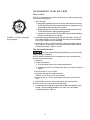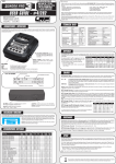
1
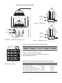
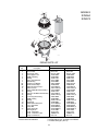
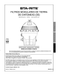
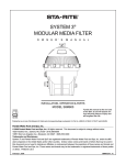
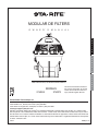
MODULAR DE FILTERS O W N E R’ S M A N U A L E N G L I S H F R A N Ç A I S INSTALLATION, OPERATION & PARTS MODELS S7MD60 S7MD72 This manual should be furnished to the end user of this filter; its use will reduce service calls and chance of injury and will lengthen filter life. Pentair Water Pool and Spa, Inc. © 2012 Pentair Water Pool and Spa, Inc. All rights reserved. This document is subject to change without notice. 1620 Hawkins Ave., Sanford, NC 27330 (919) 566-8000 10951 West Los Angeles Ave., Moorpark, CA 93021 (805) 553-5000 Customer Support: (800) 831-7133 Sta-Rite® and Pentair Water Pool and Spa® are registered trademarks of Pentair Water Pool and Spa, Inc. and/or its affiliated companies in the United States and/or other countries. Unless noted, names and brands of others that may be used in this document are not used to indicate an affiliation or endorsement between the proprietors of these names and brands and Pentair Water Pool and Spa, Inc. Those names and brands may be the trademarks or registered trademarks of those parties or others. Printed in U.S.A. 4/20/12 S596 (Rev. D) E S P A Ñ O L MODULAR DE FILTERS To avoId unneeded service calls, prevent possible injuries, and get the most out of your filter, READ THIS MANUAL CAREFULLY! The Sta-Rite System 3 Modular DE Filter: • Is designed to filter water for swimming pools. • Is an excellent performer; durable, reliable. Table of Contents Safety Instructions ....................................................................................3 General Information..................................................................................4 Installation ................................................................................................5 Specifications ...........................................................................................6 Initial Startup.............................................................................................7 Filter Disassembly / Assembly..................................................................8 Cleaning the Filter ....................................................................................9 Filter Backwash Procedure....................................................................9 Module Cleaning Procedure ................................................................10 Special Cleaning Instructions...............................................................11 System Inspection ..................................................................................11 Winterizing .............................................................................................12 Troubleshooting Guide ...........................................................................13 Repair Parts List .....................................................................................14 2 READ AND FOLLOW SAFETY INSTRUCTIONS! This is the safety alert symbol. When you see this symbol on your filter or in this manual, look for one of the following signal words and be alert to the potential for personal injury. warns about hazards that will cause death, serious personal injury, or major property damage if ignored. warns about hazards that can cause death, serious personal injury, or major property damage if ignored. warns about hazards that will or can cause minor personal injury or property damage if ignored. NOTICE indicates special instructions not related to hazards. Carefully read and follow all safety instructions in this manual and on equipment. Keep safety labels in good condition; replace if missing or damaged. Hazardous pressure. Incorrectly installed or tested equipment may fail, causing severe injury or property damage. Read and follow instructions in owner's manual when installing and operating equipment. Have a trained pool professional perform all pressure tests. 1. Do not connect system to a high pressure or city water system. 2. Use equipment only in a pool or spa installation. 3. Trapped air in system can cause explosion. BE SURE all air is out of system before operating or testing equipment. 4. DO NOT pressure test with compressed air! Before pressure testing, make the following safety checks: • Check all clamps, bolts, lids, and system accessories before testing. • Release all air in system before testing. • Tighten Sta-Rite trap lids to 30 ft. lbs. (4.1 kg-cm) torque for testing. • Water pressure for test must be less than 25 PSI (172 kPa). • Water Temperature for test must be less than 100o F. (38o C). • Limit test to 24 hours. After test, visually check system to be sure it is ready for operation. Remove trap lid and retighten hand tight only. NOTICE: These parameters apply to Sta-Rite equipment only. For non-Sta-Rite equipment, consult equipment manufacturer. BEFORE WORKING ON FILTER: If filter clamps are adjusted or removed under pressure, tank may explode, causing severe injury or major property damage. 1. Stop pump. 2. Open air release valve. 3. Release all pressure from system. BEFORE WORKING ON PUMP OR MOTOR Filter pumps require hazardous voltage which can shock, burn, or cause death. 3 Disconnect power to motor at main circuit breaker. Discharge motor capacitor to ground. GENERAL INFORMATION • Clean a new pool as well as possible before filling pool and operating filter. Excess dirt and large particles of foreign matter in the system can cause serious damage to the filter and pump. • With a diatomaceous earth (DE) filter system in place and operating correctly, clean water is returned to the pool faster than pool water is being contaminated. A typical pool installation will require approximately one week to obtain and maintain the sparkle that your filter is capable of giving you. • DO NOT use more than the recommended amount of DE in your filter. To do so can cause a buildup of DE and "bridging" between the elements which will plug the filter. If filter is improperly disassembled or assembled, it can explode under pressure! To avoid danger of severe injury or major property damage, always follow service instructions in this manual when working on filter! Hazardous pressure. Can cause severe injury or major property damage from tank blow up. Release all pressure and read instructions before working on filter. NEVER operate this filter system at more than 50 pounds per square inch (50 PSI/345kPa) pressure! Be sure filter pressure gauge operates when system is operating. If pressure gauge is damaged or does not work, replace it. Purge all air from system before operating system. NEVER operate filter with air trapped inside. • On a new pool installation, we recommend: 1. Disassemble the filter after the initial cleanup. To prevent severe injury or major property damage, exactly follow “Filter Disassembly/Assembly Procedure” on Page 8. 2. Remove and hose down the module to remove contaminants. • It is a good idea to remove the module once a year and soak it in a filter cleaning solution to remove accumulated body oils, etc.; see Page 11, “Special Cleaning Instructions”. • Cleaning interval is based on pressure differential, not on length of time filter is operated. Different water conditions will have different normal cleaning intervals. If backwashing filter is not possible, use “Module Cleaning Procedure”, Page 10, at regular intervals to clean filter. • Check local codes for restrictions on backwash to waste piping, separation tank requirements and spent D.E. disposal requirements. 4 INSTALLATION Installation of filter should only be done by qualified, licensed personnel. Filter mount must: Provide weather and freezing protection. Provide space and lighting for easy access for routine maintenance. (See Figure 1 and Table II, Page 6, for space requirements.) Be on a reasonably level surface and provide adequate drainage. Be as close to pool as possible to reduce line loss from pipe friction. Piping: Piping must conform to local/state plumbing and sanitary codes. Use thread seal tape or equivilant on all male connections of plastic pipe and fittings. DO NOT use pipe compounds on plastic pipe; it will cause the pipe to crack. Do not use sealant on unions—assemble them dry and hand tight. Support pipe independently to prevent strains on filter or valve. Use 2" (51mm) pipe to reduce pressure losses as much as possible. NOTICE: Filter may be located away from pool, but for adequate flow larger pipe may be needed. Check local codes for remote installation. Fittings restrict flow; for best efficiency use fewest possible fittings. Keep piping tight and free of leaks: pump suction line leaks may cause trapped air in filter tank or loss of prime at pump; pump discharge line leaks may show up as dampness or jets of water. NOTICE: Overtightening can crack filter ports. Valves: TABLE I - Sta-Rite valves for use with Model S7MD60 and S7MD72 filters Port Size Part Number 2" Multi-port 18201-0300 2" Plastic Slide 263053 NOTICE: Use of valves other than those listed above could cause reversed water flow through filters and damage to internal filter components. A check valve installed ahead of filter inlet will prevent contaminants from draining back into pool. A check valve installed between filter and heater will prevent hot water from backing up into filter and deforming internal components. For installation allowing backwashing, install Sta-Rite Two Position Slide Valve or Multiport Selector Valve with filter. See Table I. If you intend to clean your filter according to “Module Cleaning Procedure”, Page 10, no slide or multi-port valve is required. See Figures 1 and 2, Page 6, for correct water flow when connecting pipe. Filter ports and valve ports are furnished with union connections. DO NOT use pipe sealants on union collar (nut). Use care before assembly not to damage union sealing surfaces or ORing. To allow recirculation during precoat (if precoat pot is used), install a recirculation line with shut-off between pad return line and pump suction. Electrical All wiring, grounding and bonding of associated equipment must meet local and/or National Electrical Code standards. 5 SPECIFICATIONS Water Inlet pumped from pool D A Water Outlet To Pool E Figure 2 – Filter Cycle C 4114 1201 B INLET 7-13/16(198.4) OUTLET Waste Port to Separation tank 9-3/16(233.4) Water Inlet pumped from pool 2" (51mm)Sta-Rite Union Connections 4112 1201 FIGURE 1 – Dimensions in inches (mm) Figure 3 – Backwash Cycle 4115 1201 TABLE II - SPACE REQUIREMENTS IN INCHES (MM) Max. Flow Rate for S7MD72 (144 GPM) Max. Flow Rate for S7MD60 (120 GPM) 20 138 P.S.I. Loss 100 12 80 60 8 40 4 0 Pressure Loss in kPa 120 16 A B C* D E 281»2(724) 42(1067) 7 36(914) 531»2(1359) * Number of clamps. TABLE III - APPROVED DE CLEANERS Consult your pool service professionals for pool industry recommended filter cleaners. 20 20 40 60 80 100 120 140 160 (76) (151) (227) (303) (379) (454) (530) (606) Capacity in GPM (LPM) Pressure Drop Curve TABLE IV - FILTER SPECIFICATIONS & OPERATING INFORMATION 4113 1201 Filter Model: 2 Filter Area in Sq. Ft. (M ) Lbs. (Kg) of D.E. Used Max. Flow Rate in GPM (LPM) NSF Public Pool Flow Rate in GPM (LPM) Max. Operating Pressure in PSI (kPa) S7MD60 S7MD72 60 Sq. Ft. (5.57) 9.0 (4.1) 120 (454) 120 (454) 50 (345) 72 Sq. Ft. (6.69) 11.0 (5.0) 144 (545) 144 (545) 50 (345) NOTICE: 1/2 pound of DE will fill a one-pound coffee can. 6 INITIAL START-UP Be sure pump is OFF before starting procedure. Do not operate these filters at more than 50 PSI (345 kPa) under any circumstances! To prevent serious damage to the module fabric, NEVER run your DE filter without a diatomaceous earth precoat! Hazardous pressure. Can cause severe injury or major property damage from tank blow up. Release all pressure and read instructions before working on filter. To avoid damage to internal filter components, never change handle position on control valve while pump is running. 1. Make sure all clamps are in place and knobs are securely hand-tight. 2. Set valve to 'filter' position. 3. Fill trap on pump with water. 4. Open air release valve on top of filter assembly (Key No. 3, Page 14). 5. Start pump to purge air from system. 6. When steady stream of water comes from air release valve, close the valve. 7. To prepare precoat slurry, mix diatomaceous earth (DE) and water. See Table IV or instruction decal on filter shell for amount of DE to use. 8. Empty slurry slowly into skimmer to precoat filter element with an even filtering cake. Close valve before air is drawn into system. NOTICE: To avoid clogging the filter, do not use more DE than is specified in Table IV. After filter is operating, record filter pressure gauge reading in owner's manual for future reference on when to clean filter. NOTICE: When installed on a new pool, after approximately 48 hours of operation disassemble filter and clean out accumulated debris (see “Module Cleaning Procedure”, Page 10). To avoid severe injury or major property damage, exactly follow instructions under “Filter Disassembly/Assembly” (Page 8)! 7 FILTER DISASSEMBLY/ ASSEMBLY PROCEDURE To avoid equipment damage and personal injury, never change handle position on control valve while pump is running. BEFORE DISASSEMBLING FILTER: 1. STOP PUMP. 2. OPEN air release valve and drain fitting. 3. WAIT until all pressure is released and water drained from filter tank and system before loosening clamp knobs. Disassembly: 1. Backwash filter according to instructions under “Filter Backwash Procedure”, Page 9. Hazardous pressure. Can cause severe injury or major property damage from tank blow up. Release all pressure and read instructions before working on filter. 2. Stop pump. 3. Open air release valve (Key No. 3, Page 14) on top of filter tank to release all air pressure from inside of tank and system. 4. Remove filter drain plug and drain all water from tank. 5. To equalize flange stresses, loosen clamp knobs alternately (that is, on opposite sides of tank) around tank. Remove clamps. 6. Being careful not to damage tank O-Ring (Key No. 8, Page 14), lift upper tank shell (Key No. 7, Page 14) off lower tank shell (Key No. 21, Page 14). Assembly: 1. Remove O-Ring slowly to avoid stretching or tearing it. 2. Inspect tank O-Ring (Key No. 8, Page 14) for cuts, nicks, etc. If O-Ring is damaged, deformed, or has lost its resiliency, replace with a new one. 3. Clean O-Ring area of tank shell (both halves) and O-Ring. 4. Carefully install O-Ring and upper tank shell (Key No. 7, Page 14) on tank bottom (Key No. 21, Page 14). NOTICE: Do not lubricate O-Ring. Lubricants attract dirt and grit and may (especially when petroleum based) damage O-Ring and void warranty. NOTICE: Be sure upper tank shell contacts O-Ring surface evenly and seal area is clean and free from dirt. 5. Install clamp bolts and clamps. Do not tighten clamps yet. 6. See Figure 4 for clamp tightening sequence. Tighten all clamp knobs securely hand tight. NOTICE: To equalize stresses on tank, be sure to tighten clamps in sequence shown. DO NOT work your way around the filter tightening adjacent clamps. 7. Install air relief valve and gauge assembly on tank. 8 CLEANING THE FILTER When to Clean: NOTICE: If installation does not allow backwashing, use module cleaning procedure regularly (see Page 10). 1 5 1. With a new filter: 4 A. Record filter operating pressure at startup. When pressure reaches 10 PSI (69kPa) above startup operation pressure, stop pump for 3060 seconds to allow filtering cake to release. 3 6 7 2 FIGURE 4 - 21" Filter clamp tightening sequence. B. Restart pump to form new cake. Pressure should now be less than 10 PSI (69kPa) above startup operating pressure. C. If pressure is still more than 10 PSI (69kPa) above startup operating pressure, backwash filter (see below). 2. Thoroughly clean air bleed assembly (Key No. 9B, Page 14) on top of filter module EVERY time filter is opened. Be sure to remove all debris from screen. Replace screen if damaged. 3. At least twice a year, manually clean filter module according to instructions, Page 10. At least once a year, follow instructions under “Special Cleaning Instructions”, Page 11, as well. Filter Backwash Procedure: To prevent equipment damage and possible injury turn pump OFF before changing valve position. NOTICE: Before backwashing with a separation tank, review separation tank owner's manual for instructions. 1. Stop pump. 2. Change valve position. A. If using Multi-port Valve, set it to backwash position. B. If backwashing with a Two Position Slide Valve, push handle to full down position. 3. Start pump and run it for 3 minutes. 4. Stop pump and open tank bottom side drain. NOTICE: A 1-1/2” drain valve is recommended. 5. Start pump and run 1 minute, backwashing through filter valve and tank drain. 6. STOP PUMP, return filter valve to filter position and close tank drain. NOTICE: Do not vacuum pool while backwashing filter. 7. Compare pressure reading on gauge with reading recorded after initial startup. The two readings should be very close; if not, do "Module Cleaning Procedure", Page 10. 9 MODULE CLEANING PROCEDURE Hazardous pressure. Can cause severe injury or major property damage from tank blow up. Risk of chemical burns. Do not attempt to acid clean the filter or module. If the filter requires acid cleaning, have a trained pool professional do the job. Release all pressure and read instructions before working on filter. Follow all steps in the “Disassembly” section of this manual. When to Clean the Filter The filter module should normally be cleaned when the pressure gauge reading increases 10 PSI over the start-up pressure (record the start-up pressure in a convenient place). In some pools, accessories such as fountains or pool cleaners may be noticeably affected by the normal decrease in flow as the filter becomes dirty. If so, clean the filter more frequently (that is, at a pressure increase of less than 10 PSI) in order to maintain the required flow. Specialty Filter Cleaners Consult your pool service professionals for pool industry recommended filter cleaners. The filter module should be removed and cleaned when pressure rises more than 10 psi (69 kPa) above startup pressure. See also “When to Clean the Filter,” at left. NOTICE: Do not expose the filter module to sunlight for any extended period of time. NOTICE: When sanitizing your pool using PHMB (polyhexamethylene biquanide based) cleaners, use only PHMB cleaners to clean the module. When using PHMB sanitizers, the filter module MUST be cleaned more thoroughly and frequently than for a pool using chlorine. Follow manufacturer’s instructions carefully. Use of any other type of cleansers with PHMB pool sanitizers will void the filter’s warranty. NOTICE: Avoid washing filter debris into the outlet port. Remove drain plug and flush dirt from inside of tank before removing filter module. 1. With a hose equipped with a soft flow nozzle, wash as much dirt as possible off of the filter module while it is still inside the tank. Allow tank to drain completely. 2. Make sure that the inside of the tank is clean. Lift out the module and hose it down thoroughly. Spray the entire module surface. Allow module to drain. 3. Inspect the module. If necessary, repeat the washing operation. If the module is damaged, replace it. NOTICE: If this cleaning method does not remove all deposits, see “Special Cleaning Instructions” section in this manual. 4. Inspect and clean air bleed filter at top of module. 5. Follow all steps in the “Assembly” and “Initial Startup” sections of this manual. 10 Special Cleaning Instructions: Use this procedure to clean scale or oils which are not removed by hosing down module. Be sure to dispose of spent chemicals according to all applicable codes and waste disposal ordinances. Use a soft stream nozzle to minimize flying water and spray. Hazardous pressure. Can cause severe injury or major property damage from tank blow up. Release all pressure and read instructions before working on filter. Risk of fire or explosion. Isolate filter from system before chemical cleaning; rinse filter and elements completely before returning to service. If filter cannot be isolated, remove media and clean at another location. Follow chemical manufacturer’s instructions for use. Do not mix chemicals except as directed by manufacturer. Do not allow cleaning chemicals to mix with or to come in contact with chlorine, bromines, other chemicals, or chemical feed devices. 1. Sponge or spray the module according to chemical manufacturer’s directions. 2. If soaking is required, remove the module from the filter tank and submerge it in a separate tank. Follow cleaner manufacturer’s instructions carefully. 3. After completing chemical manufacturer’s instructions, drain and rinse the module completely. Dispose of cleaners in accordance with local codes and disposal ordinances. 4. Rinse the inside of the filter tank. Drain it completely. 5. Follow instructions in the “Assembly” and “Initial Startup” sections of this manual. SYSTEM INSPECTION General: Wash the outside of the filter with a mild detergent and water. Rinse off with a hose. NOTICE: DO NOT use solvents to clean the filter; solvents may damage plastic components in the system. NOTICE: Open the filter air release valve and release all air from the filter each time the pump is stopped and restarted. Weekly Inspection: 1. Remove debris from the pool skimmer basket. 2. Stop the pump; open the air release valve to release all pressure. 3. Remove the trap cover and basket; remove debris. 4. Check the pump for leaks. If found, see the pump owner's manual. 5. Replace the trap basket and the cover. Tighten the cover securely hand tight. DO NOT use a lid wrench to tighten it. 6. Start the pump. When the filter air release valve runs a solid stream of water, close the valve. 7. When the system has returned to normal operation, check the filter pressure. If the filter pressure is 10 PSI (69kPa) or more higher than the initial startup pressure, the filter needs cleaning. See “Cleaning the Filter”, Page 9. 11 WINTERIZING Explosion hazard. Purging the system with compressed air can cause components to explode, with risk of severe injury or death to anyone nearby. Use only a low pressure (below 5 PSI), high volume blower when air purging the pump, filter, or piping. NOTICE: Protect the filter from freezing. Allowing the filter to freeze will damage it and will void the warranty. NOTICE The filter outlet piping will not empty through the filter drain. Make sure that the outlet piping has a separate drain for winterizing. 1. Clean the filter according to instructions (Page 10) before winterizing. Do not winterize with DE precoat on cartridge or with residual in tank. 2. Stop the pump. 3. Open the air release valve; open all the system valves. 4. Remove the drain plugs from the trap, pump, and filter. 5. Drain the system piping. A. Gravity drain system as far as possible. B. Protect areas which retain water with non-toxic propylene glycol antifreeze (“RV antifreeze”). 6. Loosen the union nuts (if used) to drain all water from the filter interior. Leave these nuts loose until the system is restarted. 7. Disassemble the filter (follow instructions under “Filter Disassembly”, Page 8). Remove the filter module and store it in a warm, dry area. Be sure to store the cartridge where it will not be in sunlight. 8. Be sure to allow any water trapped in the tank to drain out. 9. Cover the filter with plastic or tarpaulin to prevent water entrance and freezing. 12 TROUBLESHOOTING GUIDE closely and clean thoroughly (see Pages 10 and 11). C. Water is chemically out of balance; consult pool professional. D. Excessive air in filter; non-precoated areas may plug. Vent air from tank and check for pump suction pipe leaks. Clean air bleed filter in grid assembly with a hose and soft flow nozzle. E. Filter is too small. Install an additional filter. F. Pool water contains iron. See “Special Cleaning Instructions”, Page 11. G. Algae in pool. Apply heavy dose of chlorine or algaecide as recommended by the pool manufacturer. H. Use of incorrect chemicals with PHMB sanitizers. Replace filter module. I. Not enough D.E. precoat. See Table IV, Page 6. 1. Short Cycle Time: NOTICE: Cycle Time will vary with each installation and between different areas of the country. The following causes and remedies are for cycle times shorter than normal for your area. A. Chlorine residual too low; maintain proper residual (consult pool professional for recommendation). B. Flow rate too high; restrict flow to rated capacity of filter (see instruction plate on filter or specifications on Page 6). C. Filter is too small; install an additional filter. D. Improper/insufficient precoat; see precoat instructions under “Initial Setup” (Page 7). E. Filter module is dirty or plugged; thoroughly clean the filter (see No. 4, “Plugged Module Cloth” (below), and “Module Cleaning Procedure", Page 10). F. Too much DE; check for clogged filter module. G. Water is chemically out of balance; consult pool professional. H. Algae in the pool. Apply heavy dose of chlorine or algicide as recommended by the pool manufacturer. 5. Pool Water Not Clean: A. Chlorine residual too low; maintain adequate chlorine residual (consult pool service technician for recommendation). B. Broken filter module passing DE into pool; replace defective module. C. Insufficient or improper precoat; follow precoating instructions and use recommended amount of DE (see Pages 6 and 7). D. Inadequate turnover rate; consult dealer to verify that equipment is properly sized for your pool. E. Pump is too large and is overpumping. Reduce the flow rate. F. The filter inlet and outlet are plumbed backwards. Re-plumb them correctly. G. Pool water contains iron. See “Special Cleaning Instructions”, Page 11. H. Heavy or improper application of powdered chlorine tablets using a binder. See “Special Cleaning Instructions”, Page 11. I. Algae in the pool. Apply heavy dose of chlorine or algicide as recommended by the pool manufacturer. 2. Low Flow/High Pressure: A. Filter Module plugged; clean module thoroughly (see Pages 10 and 11). B. Pipe blocked downstream from filter; remove obstruction. C. Piping too small; use larger pipe (consult dealer for sizing). D. Filter area too small; install an auxiliary filter (consult dealer for recommendation). E. Outlet port check valve obstructed (if applicable); remove obstruction to allow valve to open. 3. Low Flow/Low Pressure: A. Pump too small; consult dealer for recommendations. B. Plugged pump or plugged hair and lint trap; clean thoroughly. 6. Pool Accessories Stop Working: 4. Plugged Module Cloth: A. Clean filter and observe performance of accessories. B. If accessories perform better after filter has been cleaned, use a shorter cleaning cycle for the filter (that is, clean the filter after a pressure rise of less than 10 PSI). NOTICE: The pleated filter material may look matted after use. However, as long as the DE adheres to the pleated cloth, the filter is operating properly. A. Insufficient precoat; see precoat instructions (Page 7). B. Insufficient cleaning; follow cleaning instructions 13 2 25 30 3 40 0 45 5 10 15 2 0 5 1 50 MODELS S7MD60 S7MD72 3 4 55 60 5 9B 6 7 9A 8 13 14 15 21 23 22 10 12 11 16 18 17 20 4111 1201 18 19 REPAIR PARTS LIST Key No. 1 2 3 4 5 6 7 8 9A 9B 10 11 12 13 14 15 16 17 18 19 20 21 22 23 • • • • Model No. Part Description 2 Inch Gauge Screen Filter Air Release Valve Close Nipple 1/4 in. Adapter Bushing O-Ring Upper Tank Shell Kit* Tank O-Ring Replacement Module Air Bleed Assembly** Baffle Kit (with Screws)** Baffle Screws** Elbow and Bulkhead Assembly*** O-Ring Deflector and Bulkhead Assembly O-Ring 1-1/2" Plug with O-Ring Adapter Fitting O-Ring Drain Plug Bulkhead Retaining Nut Lower Tank Shell Clamp Bolt Clamp Assembly Warning Decal Decal - Nameplate Decal - Instruction Label 2" Slip 1/2 Union Kit • Not illustrated * Includes all decals and labels. S7MD60 S7MD72 33600-0023T WC8-72D WC212-120P 35202-0959 24900-0504 35505-1423 24851-9000 24850-0008 25023-0160S 24800-0120 23910-0013S 37027-7028 (4) 23910-0100S 35505-7438 23910-0101S 35505-1425 (2) 27001-002S 24900-0509 35505-1424 (2) 24900-0503 24752-0050 (2) 24850-0102S 24850-0010 (7) 24850-0200 (7) 32165-4004 32155-4147 1000001338 PKG 188 33600-0023T WC8-72D WC212-120P 35202-0959 24900-0504 35505-1423 24851-9000 24850-0008 25023-0172S 24800-0120 23910-0013S 37027-7028 (4) 23910-0100S 35505-7438 23910-0101S 35505-1425 (2) 27001-002S 24900-0509 35505-1424 (2) 24900-0503 24752-0050 (2) 24850-0102S 24850-0010 (7) 24850-0200 (7) 32165-4005 32155-4148 1000001338 PKG 188 Quantity one unless otherwise indicated ( ). ** Included with Key No. 9A Replacement Module. *** Includes O-Ring (Key No. 13). 14 Blank Page 15 Blank Page