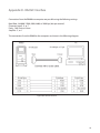
1
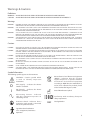
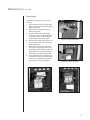
RK600
Auto Refractor / Keratometer
User’s Guide
Table of Contents
Description
Page#
Introduction......................................................................................................................................... 4
Warnings & Cautions
Definitions.................................................................................................................................... 5
Symbols......................................................................................................................................... 5
Instrument Setup
Unpacking Instructions .......................................................................................................... 6
Disengage Travel Lock............................................................................................................. 7
Application of Input Power.................................................................................................... 7
Parts Identification.................................................................................................................... 8
Icon Definition............................................................................................................................ 9
Control Buttons.......................................................................................................................... 9
Instrument Settings................................................................................................................10
Instructions for Use
Instrument Preparation.........................................................................................................11
R/K Measurement Mode.......................................................................................................12
Peripheral Measurement Mode..........................................................................................14
Printing Measurement Data................................................................................................15
Maintenance
Introduction..............................................................................................................................16
Cleaning......................................................................................................................................16
Replacement Chin Rest Pads . ............................................................................................16
Measurement Verification....................................................................................................16
Fuses.............................................................................................................................................16
Printer Paper..............................................................................................................................17
Troubleshooting
Troubleshooting Chart..........................................................................................................18
Error Message Chart .............................................................................................................19
Guidance Tables
Table 201.....................................................................................................................................20
Table 202.....................................................................................................................................21
Table 204.....................................................................................................................................22
Table 206.....................................................................................................................................23
Appendix A - General Specifications.........................................................................................24
Appendix B - RS232C Interface....................................................................................................25
Warranty..............................................................................................................................................26
Table of Figures
Figure#
S1
S2
S3
S4
S5
S6
S7
S8
S9
S10
Description
Page#
Opening Outer Box......................................................................................................................................................................6
Removing Outer Box...................................................................................................................................................................6
Opening Inner Box.......................................................................................................................................................................6
Unpacking Tray.............................................................................................................................................................................7
Accessory Tray...............................................................................................................................................................................7
Accessories.....................................................................................................................................................................................7
Travel Lock......................................................................................................................................................................................7
Operator Side Identification.....................................................................................................................................................8
Patient Side Identification.........................................................................................................................................................8
Power Panel Identification........................................................................................................................................................8
S11
Setup Menu................................................................................................................................................................................. 10
T1
T2
T3
Chin Rest Pads and Pins.......................................................................................................................................................... 11
Sample Measurement Screen............................................................................................................................................... 13
Sample Peripheral Measurement........................................................................................................................................ 14
P1
P2
R/K Print-out................................................................................................................................................................................ 15
Peripheral Print-out.................................................................................................................................................................. 15
M1
M2
M3
M4
Open Printer Door..................................................................................................................................................................... 17
Lift Printer Cutter....................................................................................................................................................................... 17
Install Paper................................................................................................................................................................................. 17
Close Printer Door..................................................................................................................................................................... 17
AB1
Appendix B - RS232C Interface............................................................................................................................................ 25
Introduction
Congratulations on your purchase of the Reichert RK600 Auto Keratometer/Refractor. The RK600 is a
combination automatic keratometer/refractor which contains innovative image processing technology to
obtain accurate keratometer and/or refractor measurements of a patient’s eyes.
This User’s Guide is designed as a training and reference manual. We recommend you carefully read and
follow the steps in this guide to ensure optimum performance from your new instrument.
Please retain this guide for your reference. This guide is designed for use with product catalog number
15035 (100 to 230 VAC input voltage). Additional copies can be obtained from your authorized Reichert
Distributor or our Customer Service Department, which can be contacted directly at:
• Tel#: (716) 686-4500,
•
Fax#: (716) 686-4555, or
•
e-mail: [email protected].
© 2005 Reichert, Inc. All rights reserved.
No part of this publication may be reproduced, stored in a retrieval system, or transmitted in any form
or by any means, electronic, mechanical, recording, or otherwise, without the prior written permission of
Reichert, Inc.
Warnings & Cautions
Definitions
Warning: An instruction that draws attention to the risk of injury or death.
Caution: An instruction that draws attention to the risk of damage to the product.
Warnings
Warning:
In order to ensure that correct operation of this instrument is maintained and to guarantee the safety
and reliability of the instrument, any repair or service must be performed by Reichert, Inc.
Warning:
This instrument should be used in strict accordance following the instructions outlined in this user’s
guide. The safety of the operator and the performance of the instrument cannot be guaranteed if used
in a manner not specified by Reichert, Inc.
warning:
This instrument must be plugged into an outlet with an earth ground which is connected to the
receptacle or damage to the unit may occur. Do not disable or remove any earth ground connection
on the instrument or any connection to this instrument or damage and/or serious injury may occur.
Warning:
This equipment or system should not be used adjacent or stacked with other equipment and if adjacent
or stacked use is necessary, the equipment or system should be observed to verify normal operation in
the configuration in which it will be used.
Cautions
caution:
ANY REPAIR OR SERVICE TO THE RK600 MUST BE PERFORMED BY EXPERIENCED PERSONNEL or dealers WHICH ARE
TRAINED BY Reichert SO THAT CORRECT operation OF THE RK600 IS MAINTAINED.
Caution:
This instrument has ELECTROSTATIC DISCHARGE SENSITIVE DEVICES (ESDS) which ARE SENSITIVE TO STATIC HIGH
VOLTAGES stored in and transferred by THE human BODY. Observe correct ESDS PRECAUTIONS or premature
MALFUNCTION of this instrument will occur.
CAUTION:
enSURE THAT THE VOLTAGE APPLIED TO THE UNIT IS THE SAME AS THE VOLTAGE WHICH IS GIVEN ON THE DATA PLATE
NEXT TO THE INPUT CORD RECEPTACLE OR DAMAGE TO THE UNIT MAY OCCUR.
caution:
this instrument is not suitable for use in the presence of flammable anesthetic mixtures, such as oxygen
or nitrous oxide.
CAUTION:
DO NOT USE SOLVENTS OR STRONG CLEANING SOLUTIONS ON ANY PART OF THis instrument OR DAMAGE TO THE
UNIT MAY OCCUR.
CAUTION:
caution:
USE OF ALCOHOL ON THE LIQUID CRYSTAL DISPLAY (LCD) MAY CAUSE DAMAGE to the Display.
the power cord is the disconnecting device from the electrical power source. Do not position the
instrument so that it is difficult to operate or disconnect the power cord from the power source.
Symbol Information
The following symbols appear on the instrument:
Waste Electrical and Electronic Equipment
( WEEE) - I ndicates that this produc t
requires disposal in a separate collection
of electronic and electrical equipment
according to WEEE directive 2002/96/EC (L
37/24) and is effective for products placed
on the market after August 13, 2005
CAUTION - Caution symbol which
is used to identify important
instructions.
O
I
OFF (Supply) - Indicates the Power
Switch is set to OFF.
ON (Supply) - Indicates the Power
Switch is set to ON.
Date of Manufacture Symbol
Alternating Current - Indicates
that this instrument operates on
alternating current.
Conformity with mandator y European
safety requirements.
Protective Earth - Indicates that a
protective earth ground is connected
where the symbol is located.
REF
Catalog Number
Type B Product Classification
Class 1 Equipment, Continuous
Operation
Instrument Setup
Great care has been taken to deliver your new RK600 Auto Keratometer/Refractor safely to you. The
container and packaging were specially designed to transport this unit. Please retain the packaging for
future use if transportation is required.
Unpacking Instructions
Please unpack the instrument in the following manner: (Refer to Figures S1 thru S6)
The instrument is packaged in a shipping container to protect the instrument from damage during
shipment. Inside the shipping container is an inner box, which contains the unit and the accessories. Please
read the User’s Guide before operating the unit.
1. Cut the straps on the outside of the box and then lift off the top of the outer box. Refer to Figure S1.
2. Lift the outer box off of its base. Refer to Figure S2.
3. Cut the straps on the inside box and open the inner box. Refer to Figure S3.
4. Remove the Manual and the Accessory Tray from the inner box. Refer to Figure S4.
5. Remove the accessories from the Accessory Tray. Refer to Figures S5 and S6. The accessories are the following:
•
Power cord
•
Dust cover
•
Spare printer paper (2 rolls)
•
Contact Lens Fixture (installed onto the Verification Eye)
•
Verification Eye
•
Box of Chin Rest Liners
•
Chin Rest Pins (2 pcs.)
•
Fuses (2 pcs., 250V @ 3A)
Note:
If any of the above accessories are not included with the unit, please call your authorized Reichert
distributor, or our Customer Service Department as indicated in the Introduction section of this
manual.
6. Store the shipping materials in a safe place, so the packaging will be available if transportation is required in the future.
Figure S1, Opening Outer Box
Figure S2, Removing Outer
Figure S3, Opening Inner Box
Instrument Setup (Continued)
Chin Rest
Liners
Power Cord
Printer Paper
Chin Rest
Figure S4, Unpacking Tray
Figure S5, Accessory Tray
Verif. Eye
Fuses
Figure S6, Accessories
Disengage Travel Lock
CAUTION: If the RK600 is transported without the travel lock
engaged, damage to the instrument may occur
causing incorrect readings and/or failure of its
electronic or mechanical parts.
•
Place the RK600 in the location where it will be utilized.
•
The Travel Lock is located on the lower left front corner of the
instrument. Rotate the knob counterclockwise to disengage the
Travel Lock. Refer to Figure S7.
Note:
If at any time this instrument is relocated, engage the Travel
Lock prior to moving the instrument. If this instrument is
transported to a different location, engage the Travel Lock
and then secure the instrument into its original packaging.
Figure S7, Travel Lock
Application of Input Power
CAUTION: MAKE SURE THAT THE VOLTAGE APPLIED TO THE UNIT IS THE SAME AS THE VOLTAGE GIVEN ON THE
DATA PLATE NEXT TO THE INPUT CORD RECEPTACLE OR DAMAGE TO THE UNIT MAY OCCUR.
•
After the unit is secure and the travel lock is disengaged, apply power to the instrument using the
Power Cord which was contained in the Accessory Tray.
•
Read and fully understand the User’s Guide and the Quick Reference Card before operating this instrument.
Instrument Setup (Continued)
LCD Screen
Headrest
Control
Buttons
Chin Rest Pins
Printer Door
Chin Rest Pads
Chin Rest
Fire Button
Vertical
Adjustment
Knob
Joystick
Travel Lock
Figure S8, Operator Side Identification
Power
Switch
Figure S9, Patient Side
250V, 3A
Fuses
Input
Power
Video Out
Port
RS232C
Port
Figure S10, Power Panel
Parts Identification
LCD Screen:
Operator display providing measurement data.
Control Buttons:
Buttons for selecting options on the Operator Display.
Printer Door:
Printer door (push to open) to access travel lock and
printer paper.
Joystick:
Positioning device used for alignment.
Fire Button:
Button that is pressed in the Manual mode to acquire a
measurement.
Travel lock:
Locking mechanism which secures the internal parts of
the unit during shipment.
Headrest:
Horizontal reference point for the forehead.
Chin Rest Pins:
Pins that secure the Headrest Pads onto the Chin Rest.
Chin Rest Pads:
Disposable pads for use on the chin rest.
Chin Rest:
Adjustable positioning point for the patient’s chin.
Vertical Adjustment Knob:
Knob that adjusts the height of the Chin Rest.
Power Switch:
ON/OFF switch that controls input power to the unit.
Fuses:
250V, 3A fuses (2pcs. per unit) for overcurrent protection.
Input Power:
Interface for connecting input power to the unit.
Video Out Port:
interface for connecting an external video monitor.
RS-232C Port:
Communication port which contains printer data.
Instrument Setup (Continued)
Icon Definition
The RK600 incorporates a user-friendly icon/menu-based operating system which will increase the speed
of measurements, training, and use. Below are the Icons which are used during the operation of this
instrument.
Icon
Icon Description
If this icon is shown, the refraction data is displayed in the 1/8 diopter mode.
If this icon is shown, the refraction data is displayed in the 1/4 diopter mode.
When this icon is displayed, the plus (+) cylinder mode is active.
When this icon is displayed, the minus (-) cylinder mode is active.
When this icon is displayed, either the plus (+) or the minus (-) mode as “best”
determined by the instrument is active.
Displays that the unit is ready to take a left eye measurement.
Displays that the unit is ready to take a right eye measurement.
The number displayed to the right of this icon is the keratometric reading.
The number displayed to the right of this icon is the refraction reading.
Indicates a vertex distance of zero (0) millimeters (contact lens prescription).
Indicates a vertex distance of 10 millimeters.
Indicates a vertex distance of 12 millimeters.
Indicates a vertex distance of 13.5 millimeters.
Indicates a vertex distance of 15 millimeters.
Icon
Control Buttons
Press this button to erase the current data displayed on the screen.
Measurement mode for Refraction, and/or Keratometric, or Peripheral mode.
Options are: R/K (Refraction and Keratometric), R (Refraction only), K
(Keratometric only, or P.K. (Peripheral Keratometric) measurements.
When this button is depressed, the setup menu is displayed to change the system
options.
Press this button when a print-out is desired. For an automatic print-out after
readings are acquired, go to the setup menu and set the print option to “auto.”
Press this button to change to the next position (peripheral measurement mode
only).
Instrument Setup (Continued)
Instrument Settings
This instrument has default parameters that may be changed to accommodate user preferences for each
setting. Refer to the illustration below.
Press the UP or DOWN arrow to select the desired setting, then the LEFT/
RIGHT arrow to change the parameter for the desired setting. After completing changes, press the RETURN arrow to exit the setup mode. Setting
descriptions are as follows:
STEP
0.25
VD(mm) 0 10
CYL
–
+
MEASURE
0.12
12 13.5 15
±
AUTO MANUAL
STEP
Rounding mode for the refractive measurements.
Available options are: 0.25, or 0.12 Diopters.
VD(mm)
Vertex Distance for the refractive measurements.
0ptions are: 10, 12, 13.5, or 15 millimeters.
CYL
Format that the refractive prescription is displayed.
Options include: –Cyl, +Cyl, or ±Cyl mode.
MEASURE
AUTO: Automatically takes a measurement when the
patient is properly aligned to the instrument.
MANUAL: The instrument will acquire a measurement
when the fire button is depressed.
KERATO
Units of measurement of the keratometric measurement.
Options are: Radius (mm), or Diopter (D).
PRINT AUTO: This mode automatically prints the data after both
the left and right eye data are acquired.
MANUAL: To print in this mode, the print button must be
pressed after the readings are acquired.
OFF: The printer does not print when the print button is
pressed.
ERASE VALUE This mode allows the user to set the instrument to automatically clear the screen of all values after printing. To
make this the default, select ON. If manually clearing the screen after printing is preferable, simply set the default
to OFF.
REVIEW DATA ON: When set to ON, the Review Data screen is shown after both the right and left data are acquired.
OFF: When set to OFF, the screen does not change to the Review Data screen after data is acquired.
W-D(cm)
ON: Sets the working distance when near point refraction data is requested (NPD). Options are: 30, 35, 40, or 45
centimeters
OFF: This option is not utilized.
TARGET LIGHT
Sets the brightness of the patient target light. Options are: Bright, Normal, or Dark.
CONTRAST
Sets the contrast of the LCD screen. This is a graduated scale modified by pressing the Left/Right arrow.
SLEEP (MIN.)
Time period of inactivity when the sleep mode activates. In this mode the LCD screen is set OFF and the green LED
(at the bottom right of the LCD) is ON. Options are: 3, 5, or 10 minutes, or OFF (LCD always on).
TONE
Volume level for the audible (beep) indicator. Options are: High, Low, or Off.
OPTIONS
MESSAGE: When the RETURN arrow is pressed for this option, a screen appears requesting a text message (up to 22
characters) that is included on the top of the print-out (e.g., practice name, phone number, etc.).
Note: This option allows an individualized operator’s number to appear on the print-out. This provides identification
KERATO RADIUS DIOPT
PRINT AUTO MANUAL OFF
ERASE VALUE
AFTER PRINT ON OFF
REVIEW DATA ON OFF
W-D(cm) OFF 30 35 40 45
TARGET LIGHT
BRIGHT NORMAL DARK
CONTRAST >>>>>>>>>>>>>>>>>>>>>>
Figure S11. Setup Menu
of the operator (examiner) when reviewing the patient data on the print-out.
RS232C: Allows modification of the RS232C data bus parameters. When the RETURN arrow is pressed for this option,
a screen appears requesting Baud Rate, Character (7 or 8), Parity, and Stop Bits.
DATE FORM
Format the date on the print-out appears. YMD, DMY, or MDY.
DATE
Setting for current date.
TIME
Setting for current time.
10
Instructions for Use
Instrument Preparation
The RK600 is an advanced electronic refractometer/keratometer which quickly acquires precise data of
the human eye. The information below will assist you in detailing the initial steps to obtain optimum
performance of this instrument.
Perform the following steps after removing the RK600 from its shipping container.
1. Install the unit in its permanent location and then ensure that the Travel Lock has been disengaged.
2. Remove the plastic protector that is installed onto the LCD Screen to prevent scratches and contaminants on the screen.
3. Install an adequate supply of Chin Rest Pads onto the Chin Rest and secure them with the Chin Rest
Pins. Refer to Figure T1.
4. Install the Printer Paper as indicated in the Maintenance section of this manual.
Figure T1. Chin Rest Pads and Pins
11
Instructions for Use (Continued)
R/K Measurement Mode
Measurement Modes
The RK600 has six measurement modes:
R/K
Refraction and keratometric data
R
Refraction only data
K
Keratometric only data
P.K.
Peripheral keratometric data.
IOL R/K Refraction and keratometric data, utilizing IOL filtering
IOL R
Refraction only data, utilizing IOL filtering
Note:
When power is applied to the RK600, the instrument automatically
displays the last used measurement mode.
Note:
When acquiring IOL patient data, it is recommended that the IOL option
be used. Using IOL filter options for non-IOL patients may cause
occasional measurement difficulty for patients with reduced pupil
diameters.
The following information describes the correct method for acquiring refractor
and keratometer measurements using the RK600.
1. Ask the patient to place their chin on the Chin Rest and then move their
head forward until their forehead is placed against the Headrest.
2. Adjust the Vertical Alignment Knob and move the Joystick until the patient
can view the fixation target (the house) with their right eye.
3. Twist the Joystick until the pupil is vertically centered on the LCD Screen.
4. Move the Joystick left, right, in and out until the circle is in focus and the
PLUS icon (+) is in the center of the circle.
•
If the instrument is set for the AUTO mode, the measurements will
automatically be acquired when alignment is achieved.
•
If the instrument is set for the MANUAL mode, the Fire Button must be
depressed to acquire a measurement when alignment is achieved.
5. Repeat the above steps for the left eye.
6. Press the PRINT button if a print-out of the measurements is desired .
12
Instructions for Use (Continued)
R/K Measurement Mode (Continued)
Measurement Data
Data for the measurements acquired in the R/K, R, or K measurement modes is
displayed on the LCD Screen. A summary of the data is given below. Refer to
Figure T2.
R Indicates refractive measurements.
K Indicates keratometric measurements.
S Sphere values
C Cylinder Values
A Axis angle
R1 Radius of curvature (max)
R2 Radius of curvature (min)
PD Pupillary distance
NPD Near pupillary distance*
* Displayed only when a value is set for the W-D (working distance) in the
SETUP mode.
Figure T2. Sample Measurement Screen
13
Instructions for Use (Continued)
Peripheral Measurement Mode
Peripheral measurements are measurements of the eye which are taken at its
center and four equidistant points around the eye to determine the curvature of
the cornea. The peripheral section of this instrument acquires five measurements;
one at the center, and four measurements (superior, temporal, inferior, and nasal)
which are equidistant from the center of the eye and each other. To acquire a
peripheral measurement, the patient fixates on the peripheral diode and the
operator aligns the instrument to the center of the target.
Perform the following steps to take a peripheral measurement:
1.
Press the button below the MODE button until the PERIPHERAL icon is shown for the
peripheral mode. In this mode, the peripheral icon is displayed on the LCD and the active position is indicated by the blinking segment.
2.
The middle segment is the first blinking segment. Align the instrument to the right
eye and press the FIRE button (on top of the Joystick) when the PLUS (+) icon is in
focus (IN and OUT distance) and is at the center of the circle on the Operator Screen.
3.
Instruct the patient to fixate on the red LED. When the patient is ready, align the PLUS
(+) icon so that it is in focus (IN and OUT distance) and is at the center of the circle on
the Operator Screen, and then press the FIRE button.
Note:
The red LED that the patient observes is opposite in position to the blinking
segment of the peripheral icon. The blinking segment relates to the position on
the eye that is measured (when the patient looks down, the area above the center
of the eye is measured).
4.
Repeat the above step until all four peripheral measurements are acquired.
5.
Repeat the above steps for the other (left) eye.
The definitions of the peripheral data categories on the screen (or print-out) are
as follows:
C = Measurement at the center of the eye
T = Measurement at 30 degrees from the center of the eye on temporal side of the
eye.
N = Measurement at 30 degrees from the center of the eye on nasal side of the eye.
S = Measurement at 30 degrees from the center of the eye on superior side of the eye.
I = Measurement at 30 degrees from the center of the eye on inferior side of the eye.
e = Eccentricity of the eye, average total.
H = Eccentricity of the eye in the horizontal meridian.
V = Eccentricity of the eye in the vertical meridian.
Figure T3. Sample Peripheral Measurement
14
Instructions for Use (Continued)
Printing Measurement Data
The print function in this instrument has three options.
• Automatic mode - This option automatically prints out the data after all
measurements are taken on both the right and left sides.
•
Manual mode - This option prints out the data only when the print button is
pressed.
•
Additionally, the printer can be set to the OFF mode. In this mode the
printer does not print even if the print button is pressed, and the data is sent
to the serial port instead of the printer.
Figure P1. R-K Print-out
Figure P2. Peripheral Print-out
15
Maintenance
Introduction
The RK600 requires very little routine maintenance due to its advanced design.
For instance, there are no bulbs or lamps to change.
If you have questions regarding maintenance, contact your local distributor, or
our Customer Service Department directly at (716) 686-4500.
Cleaning
CAUTION: DO NOT USE ALCOHOL or any solvents on any external surface
of the instrument OR DAMAGE TO T HE Painted or coated
SURFACE may occur.
Joystick
Clean external surfaces of the Joystick using a clean, soft cloth that is only
lightly dampened with a mild detergent solution (1 cc of liquid dish soap to
one liter of clean filtered water (e.g., filtered below 5 microns)).
Operator Display
Clean the Operator Display using a clean, soft cloth that is only lightly
dampened with a mild detergent solution (1 cc of liquid dish soap to one liter
of clean filtered water (e.g., filtered below 5 microns).
Patient Mire Window
Clean the Patient Mire Window using a clean, soft cloth that is only lightly
dampened with a mild detergent solution (1 cc of liquid dish soap to one liter
of clean filtered water (e.g., filtered below 5 microns).
Instrument Covers
Clean external surfaces of Instrument Covers using a clean, soft cloth that is
only lightly dampened with a mild detergent solution (1 cc of liquid dish soap
to one liter of clean filtered water (e.g., filtered below 5 microns).
Replacement Chin Rest Pads
For hygienic reasons, replaceable Chin Rest Pads are included with this
instrument. After a patient is measured, it is recommended by Reichert that the
top Chin Rest Pad be discarded so that hygienic conditions are maintained.
Measurement Verification
Included with this instrument is a Model Eye that may be used to simulate a
measurement on a patient. Use this Model Eye when a performance check of
the unit is desired. To acquire a measurement using this eye, remove the Chin
Rest Pads and install the Model Eye onto the Chin Rest. Measurements acquired
using this eye must be within the tolerances indicated on the Model Eye. If the
measurements are not within tolerance, check the mounting and position of the
Model Eye then acquire another measurement. If the measurement is still not
within tolerance, contact your authorized Reichert distributor, or the Reichert
Customer Service Department as indicated in the Introduction section of this
manual.
Fuses
Fuses are located next to the power inlet (Refer to page 8). Only replace with
fuses recommended by Reichert.
16
Maintenance (Continued)
Printer Paper
Installation of the printer paper is quick
and easy.
1. Open the Printer Door by pushing the
Door Latch down and pulling forward.
Refer to Figure M1.
2. Lift the Printer Cutter Assembly up.
Refer to Figure M2.
3. Install the Printer Paper behind the
Roller Bar and turn the Roller Bar Knob
so that the paper is pushed through
the Roller Bar. Refer to Figure M3.
4. Push the Printer Paper through the cutter bar of the Printer Cutter Assembly.
Refer to Figure M3.
5. Return the Printer Cutter to its original position and gently pull the paper
through the Printer Cutter to allow the
Printer Paper to be installed through
the Printer Door. Refer to Figure M4.
6. Close the Printer Door and gently pull
on the Printer Paper so that the Printer
Paper is not stuck between the printer
and the door. Refer to Figure M4.
Figure M3, Install Paper
Figure M1, Open Printer Door
Figure M2, Lift Printer Cutter
Figure M4, Close Printer Door
17
Troubleshooting (Continued)
Troubleshooting Chart
The following chart provides details of common difficulties and solutions for the RK600 .
ERROR
MESSAGE
REMEDY
SYSTEM
Screen blank.
Unit may be in the “sleep”
mode, push any button to
continue.
Unit will not move left/right or
in/out.
Travel lock may be engaged. Disengage the
travel lock.
Joystick will not move easily.
Contact your Reichert Authorized Dealer for repair
of this instrument.
Clock/date incorrect.
Change settings in setup.
Battery in the unit is out of
power.
Fuse is blown when power is
applied.
Contact your Reichert Authorized Dealer for repair
of this instrument.
Will not print.
Out of paper.
Printer not turned on in
setup. Paper installed upside down.
Paper jams in printer.
Paper installed incorrectly.
Re-install paper as indicated in the manual.
No power.
Check fuses and/or power
outlet/ power cord.
PRINTER
If problems still persist, contact your local dealer or Reichert, Inc.
NOTE: Circuit diagrams, component parts list descriptions and calibration instructions are available only to
the qualified personnel.
18
Troubleshooting (Continued)
The following chart provides details of common error messages for the RK600.
MESSAGE
CAUSE
REMEDY
RETRY
Patient eye moved.
Wrong alignment.
Have the patient remain still and fixate
on the target.
Realign the patient and take a new
measurement.
SPH OVER
Exceeded sphere measurement
range (± 25D).
Measure within the sphere range.
CYL OVER
Exceeded cylinder measurement
range (± 10D).
Measure within the cylinder range.
MOTOR FAULT
Motor fault in motor control
system.
Reset power to the unit and take a new
measurement.
EEPROM FAULT
EEPROM failed to initialize.
Reset power to the unit.
PRINTER CUTTER
HEAD UP
Printer cutter head is up or not
engaged.
Open and then close the printer cutter
head to reset the sensor.
PRINTER HEAD
OVER HEAT
Printer head is over-heating.
Contact your Reichert Authorized
Dealer for repair of this instrument.
PRINTER CUTTER
FAULT
Paper jam in the printer .
Clean out the printer jam.
No printer paper in the printer.
Install printer paper in the printer as
indicated in this manual.
PAPER EMPTY
If problems still persist, contact your local dealer or Reichert, Inc.
NOTE: Circuit diagrams, component parts list descriptions and calibration instructions are available only to
qualified personnel.
19
Guidance Tables
Table 201
Table 201 - Guidance and Manufacturer’s Declaration - Emissions
All Equipment and Systems
Guidance and Manufacturer’s Declaration - Emissions
The 15035 Rev. C is intended for use in the electromagnetic environment specified
below. The customer or user of the 15035 Rev. C should ensure that it is used in
such an environment.
Emissions Test
Electromagnetic Environment - Guidance
Group 1
The 15035 Rev. C uses RF energy only for its
internal function. Therefore, it’s RF emissions
are very low and are not likely to cause any
interference in nearby electronic equipment.
RF Emissions
CISPR 11
Class A
The 15035 Rev. C is suitable for use in all
establishments other than domestic and
those directly connected to the public lowvoltage power supply network that supplies
buildings used for domestic purposes.
Harmonics
IEC 61000-3-2
Class A
Flicker IEC
61000-3-3
Complies
RF Emissions
CISPR 11
20
Compliance
Guidance Tables
Table 202
Table 202 - Guidance and Manufacturer’s Declaration - Immunity
All Equipment and Systems
Guidance and Manufacturer’s Declaration - Immunity
The 15035 Rev. C is intended for use in the electromagnetic environment specified below. The
customer or user of the 15035 Rev. C should ensure that it is used in such an environment.
IEC 60601
Test Level
Immunity Test
ESD
IEC 61000-4-2
±6kV Contact
±8kV Air
Compliance Level
Electromagnetic
Environment - Guidance
±6kV Contact
±8kV Air
Floors should be wood,
concrete or ceramic tile.
If floors are synthetic,
the r/h should be at least
30%
EFT
IEC 61000-4-4
±2kV Mains
±1kV I/Os
±2kV Mains
±1kV I/Os
Mains power quality
should be that of a
typical commercial or
hospital environment.
Surge
IEC 61000-4-5
±1kV Differential
±2kV Common
±1kV Differential
±2kV Common
Mains power quality
should be that of a
typical commercial or
hospital environment.
>95% Dip for
0.5 Cycle
>95% Dip for
0.5 Cycle
60% Dip for
5 Cycles
60% Dip for
5 Cycles
30% Dip for
25 Cycles
30% Dip for
25 Cycles
>95% Dip for 5
Seconds
>95% Dip for 5
Seconds
Voltage Dips/Dropout
EIC 61000-4-11
Power Frequency
50/60 Hz
Magnetic Field
IEC 61000-4-8
3A/m
3A/m
Mains power quality
should be that of a
typical commercial or
hospital enviroment. If
the user of the 15035
Rev. C requires continued
operation during power
mains interruptions, it is
recommended that the
15035 Rev. C be powered
from an uninterruptible
power supply or battery.
Power frequency
magnetic fields should
be that of a typical
commercial or hospital
environment.
21
Guidance Tables
Table 204
Table 204 - Guidance and Manufacturer’s Declaration - Emissions
Equipment and Systems that are NOT Life-Supporting
Guidance and Manufacturer’s Declaration - Emissions
The 15035 Rev. C is intended for use in the electromagnetic environment specified below. The
customer or user of the 15035 Rev. C should ensure that is it used in such an environment.
Immunity Test
IEC 60601
Test Level
Compliance
Level
Electromagnetic Environment - Guidance
Portable and mobile communications
equipment should be separated from the
15035 Rev. C by no less than the distances
calculated/listed below:
D=(3.5/V1)(Sqrt P)
Conducted RF
IEC 61000-4-6
Radiated RF
IEC 61000-4-3
3 Vrms
150 kHz to
80 MHz
3 V/m
80 MHz to
2.5 GHz
(V1)=3Vrms
(E1)=3V/m
D=(3.5/E1)(Sqrt P)
80 to 800 MHz
D=(7/E1)(Sqrt P)
800 MHz to 2.5 GHz
Where P is the max power in watts and D
is the recommended separation distance in
meters.
Field strengths from fixed transmitters, as
determined by an electromagnetic site survey,
should be less than the compliance levels (V1
and E1).
Interference may occur in the vicinity of
equipment containing a transmitter.
22
Guidance Tables
Table 206
Table 206 - Recommended Separation Distances between portable and mobile RF
Communications equipment and the 15035 Rev. C Equipment and Systems that are NOT
Life-Supporting
Recommended Separations Distances for the 15035 Rev. B
The 15035 Rev. C is intended for use in the electromagnetic environment in which radiated
disturbances are controlled. The customer or user of the 15035 Rev. C can help prevent
electromagnetic interference by maintaining a minimum distance between portable and mobile
RF Communications Equipment and the 15035 Rev. C as recommended below, according to the
maximum output power of the communications equipment.
Separation (m)
150kHz to 80 MHz
Separation (m)
80 to 800 MHz
Separation (m)
800MHz to 2.5GHz
D=1.1667 (Sqrt P)
D=1.1667 (Sqrt P)
D=2.3333(Sqrt P)
0.01
0.11667
0.11667
0.23333
0.1
0.36894
0.36894
0.73785
1
1.1667
1.1667
2.3333
10
3.6894
3.6894
7.3785
100
11.667
11.667
23.333
Max Output Power
(Watts)
23
Appendix A - General Specifications
Keratometer
Radius of Curvature:
Corneal Power:
Cylinder:
Axis:
Peripheral
Refractor
Sphere
Cylinder
Axis
Measurement Accuracy
Sphere
Cylinder
5.00 mm thru 10.00 mm (0.01 mm steps)
33.75D thru 67.50D (0.12D, 0.25D steps)
0 thru 9.0D
00 thru 1800 (10 steps)
4 points at 300 from apex
-25.00D thru +25.00D (0.01D, 0.12D, 0.25D steps)
-10.00 thru +10.00D
00 thru 1800 (10 steps)
-10.00D thru +10.00D = ±0.25D, else 0.50D
±0.25D
Other
PD Range
85mm, 1mm steps
Pupil Diameter Min.
2.3mm (> 2.3mm increases standard measurement error)
Vertical Adjustment(Chin Rest) ±30.0mm
Physical Data
Height:
Depth:
Width:
Weight, unpacked:
Electrical Data
Voltage (nominal)
Power
Frequency
Fuses
17.2 in. (437mm)
16.6 in. (422mm)
9.4 in. (240mm)
33 lbs. (15.0 kg)
100 ~ 240 VAC
80 VA
50/60 Hz
250 VAC, 3 Amps
Transportation & Storage
This instrument can withstand the following conditions while packed for transportation or storage:
• an atmospheric pressure range of 760 mmHg (101 kPa) thru 528 mmHg (70.4 kPa)
• an ambient temperature range from, -10 °C thru +60 °C
• a relative humidity range of 30% thru 85%
Note: Operating conditions are recommended from +10 °C thru +40 °C at a relative humidity of 40% thru
70%.
Note: The extreme high or low storage conditions shown above should not exceed 15 weeks.
Disposal
This product does not generate any environmentally hazardous residues. At the end of product life, follow
local laws and ordinances regarding proper disposal of this equipment.
Applicable Laws and Standards
Law
Electromagnetic Compatibility Directive 89/336/EEC
Low Voltage Directive 72/23/EEC
Waste Electrical and Electronic Equipment (WEEE) Directive 2002/96/EC
Standard
Safety of a device - EN 61010-1: 2001
Electromagnetic Compatibility - EN 61326-1: 1997, Amendment A2: 2001 Class A
24
Appendix B - RS232C Interface
Connections from the RK600 to a computer are possible using the following settings:
Baud Rate: 384000, 19200, 9600, 4800, or 2400 bps (bits per second)
Character (word): 8, or 7
Parity: Odd, Even, or None
Stop Bits: 2, or 1
The connections from the RK600 to the computer are shown in the following diagram :
Figure AB1. RS232C Interface
25
Warranty
This product is warranted by Reichert, Inc. (Reichert)
against defective material and workmanship under
normal use for a period of one year from the date
of invoice to the original purchaser. (An authorized
dealer shall not be considered an original purchaser.)
Under this warranty, Reichert’s sole obligation is to
repair or replace the defective part or product at
Reichert’s discretion.
This warranty applies to new products and does not
apply to a product which has been tampered with,
altered in any way, misused, damaged by accident
or negligence, or which has the serial number
removed, altered or effaced. Nor shall this warranty
be extended to a product installed or operated in
a manner not in accordance with the applicable
Reichert instruction manual, nor to a product which
has been sold, serviced, installed or repaired other
than by a Reichert factory, Technical Service Center,
or authorized Reichert, Inc. Dealer.
Lamps, bulbs, charts, cards and other expendable
items are not covered by this warranty.
All claims under this warranty must be in writing
directed to the Reichert factory, Technical Service
Center, or authorized instrument dealer making the
original sale and must be accompanied by a copy
of the purchaser’s invoice with serial numbers. Any
product returned for service must have a Return
Material Authorization (RMA) and be packed in
factory packaging.
This warrant y is in lieu of all other warranties
implied or expressed. All implied warranties of
merchantability or fitness for a particular use are
hereby disclaimed. No representative or other
person is authorized to make any other obligations
for Reichert. Reichert shall not be liable for any
special, incidental, or consequent damages for any
negligence, breach of warranty, strict liability or any
other damages resulting from or relating to design,
manufacture, sale, use or handling of the product.
PATENT WARRANTY
If notified promptly in writing of any action brought
against the purchaser based on a claim that the
instrument infringes a U.S. Patent, Reicher t will
defend such action at its expense and will pay costs
and damages awarded in any such action, provided
that Reichert shall have sole control of the defense
of any such action with information and assistance
(at Reichert’s expense) for such defense, and of all
negotiation for the settlement and compromise
thereof.
26
PRODUCT CHANGES
Reichert reserves the right to make changes in design
or to make additions to or improvements in its
products without obligation to add such to products
previously manufactured. CLAIMS FOR SHORTAGES
We use extreme care in selection, checking, rechecking
and packing to eliminate the possibility of error. If any
shipping errors are discovered:
1. Carefully go through the packing materials to
be sure nothing was inadvertently overlooked
when the unit was unpacked.
2. Call the dealer you purchased the product from
and report the shortage. The materials are
packed at the factory and none should be missing if the box has never been opened.
3. Claims should be filed within 30 days.
CLAIMS FOR DAMAGES IN TRANSIT
Our shipping responsibility ceases with the safe
delivery in good condition to the transportation
company. Claims for loss or damage in transit should
be made promptly and directly to the transportation
company.
If, upon delivery, the outside of the packing case
shows evidence of rough handling or damage, the
transportation company’s agent should be requested
to make a “Received in Bad Order ” notation on
the delivery receipt. If within 48 hours of delivery,
concealed damage is noted upon unpacking the
shipment and no exterior evidence of rough handling
is apparent, the transportation company should be
requested to make out a “Bad Order” report. This
procedure is necessary in order for the dealer to
maintain the right of recovery from the carrier.
Notes
27
Reichert, Inc.
3362 Walden Ave
Depew, NY 14043
USA
Toll Free: 888-849-8955
Phone: 716-686-4500
www.reichertoi.com
Reichert GmbH
Hubertusstrasse 2
D-82229 Seefeld
Germany
Tel: +49-8152-993530
ISO-9001 Certified
15035-101-Rev. D