1
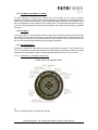
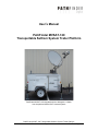
User’s Manual
PathFinder MVSAT-120
Transportable SatCom System Trailer Platform
PathFinder MVSAT-120 integrated with the Winegard 1.2 Meter
Auto Acquisition Mobile VSAT Antenna System
PathFinder MVSAT-120 Transportable SatCom System Trailer Platform
User’s Manual 11.30.08 Rev 1
Page 1 of 26
PathFinderDigital.net
Table of Contents
INTRODUCTION
General Description
Standard Features
Specifications
Available Options
SAFETY PRECAUTIONS
General Safety Information
Proper Hitch Use
Stabilizer & Tongue Jack Use
Wiring Diagrams and Connector Type
Wheel Lug Nuts Inspection & Maintenance
Tire Safety Information
Base Trailer Warranty Information
TOWING
PREPARING FOR DEPLOYMENT AND USE
DEPLOYMENT AND OPERATION
STOWING AND TRANSPORTATION
INDIVIDUAL SUBSYSTEMS EXPLANATIONS
AC Electrical System
Forced Air Ventilation System
Honda Generator System
REQUIRED ROUTINE MAINTENANCE
Wheel Bearing Maintenance
Break-Away Switch Maintenance
Trailer Lights & Brake Wiring Maintenance
Trailer Suspension Inspection & Maintenance
Door Weather Stripping Inspection & Maintenance
Overall Weather Seal / Water-Proofing
ADDENDUM 1
Proper Hitch Use
ADDENDUM 2
Stabilizer & Tongue Jack Use
ADDENDUM 3
Wiring Diagrams and Connector Type
ADDENDUM 4
Wheel Lug Nuts Inspection & Maintenance
ADDENDUM 5
Tire Safety Information
ADDENDUM 6
Base Trailer Warranty Information
PATHFINDER CONTACT INFORMATION
3
3
4
4
5
5
5
Addendum 1
Addendum 2
Addendum 3
Addendum 4
Addendum 5
Addendum 6
6
7
7
8
9
9
10
11
13
13
13
13
14
14
14
15
16
17
18
19
25
26
PathFinder MVSAT-120 Transportable SatCom System Trailer Platform
User’s Manual 11.30.08 Rev 1
Page 2 of 26
PathFinderDigital.net
Introduction:
The PathFinder Digital Model PFD-MVSAT-120 Transportable SatCom System Platform is a
compact, lightweight custom communications trailer. A rigid roof structure provides a solid
platform for the installation and integration of any manufacturer’s satellite antenna system up to
1.2 meters in size. A shock mounted 15RU equipment rack is standard, providing space for the
equipment necessary to render data, voice, and/or video communications.
The lightweight and compact design allows for towing behind a standard SUV, van, or pickup
truck that is equipped with a minimum class 1 hitch. Manually operated stabilizer jacks on all four
corners offer added stability.
The trailer is segmented into forward and rear compartments. The communications equipment is
rack mounted in the front compartment which is sealed & locked away from the elements. The
rear compartment provides plenty of space for transport and storage of other required equipment.
The communications equipment, custom I/O cable hatch, and AC power input is curb side
accessible. Included are two independent 120 Volt AC 15 Amp circuits and a 1400 VA UPS.
The rear trunk offers 50 cubic feet of storage with ample space to carry a full sized generator, fuel
can, spare tire, tools, and any ancillary equipment as needed.
PathFinder Digital offers value added services that includes the installation, integration, and
commissioning of customer provided equipment to render fully operational systems.
PathFinder MVSAT-120 Transportable SatCom System Trailer Platform
User’s Manual 11.30.08 Rev 1
Page 3 of 26
PathFinderDigital.net
Standard Features:
Trailer Model
Manufacturer
Stability
Access
Spare Tire
Storage
Rack Space
I/O Interface
Trailer Power
Uninterruptible Power System
(UPS)
Air Flow Venting
PFD-MVSAT-120
Transhaul / PathFinder Digital exclusive
4 stabilizing jacks on 4 corners
2 front side doors, 1 rear door
Included and stored in rear trunk
50 cubic feet in rear compartment accessible via rear door
Standard single 15 RU shock mounted rack in front compartment
Custom 1 RU 16 port panel configurable per application on curb side of trailer
120 VAC 30 Amp twist lock plug supplying two independent 15 Amp circuits
1400VA / 950 Watt UPS included for backup of basic communication equipment
Forced air ventilation in front compartment, flow-thru ventilation in rear compartment
Specifications:
Trailer Weight
•
Base Trailer (Empty)
Tongue Weight
•
Empty
•
With antenna & equipment
Load Capacity
•
GVWR
•
Payload
Tires
•
Type
•
Load Range
•
Speed Rating
•
Max Capacity
•
Maximum PSI
Hitch on Trailer
•
Tongue Type
•
Ball Size
Hitch Requirements on
Vehicle
•
Class 1
•
Class 2
Trailer Brakes
•
Electric Brakes
Lighting
•
Front Side Marker
•
Rear Side Marker
•
Rear Tail Lights
12 Volt Wiring Harness
•
Connector Type
Trailer Dimensions
•
Overall Height
•
Overall Width
•
Overall Length
•
Body Dimensions
1,000 Lbs. approximate
90 - 100 Lbs.
125-135 Lbs.
2,990 Lbs.
1,990 Lbs.
ST205/75D-15, Bias Ply
Load Range C (6 Ply)
Highway rated - high speed
1,820 Lbs. each
50 Lbs.
A Frame rated at 5,000 Lbs.
2”
Up to 200 Lbs. tongue weight
Up to 2,000 Lbs. gross trailer weight
Up to 300 Lbs. tongue weight
Up to 3,500 Lbs. gross trailer weight
Electric trailer brakes with break away switch
Amber on each side
Red on each side
Red on the rear left & right, integrated taillights, brake lights, and turn signal lights
Bargman 7 (RV Style) 12 volt electrical connectors for lights and brakes
58”
81”
128 ½”
60” Wide X 84” Long X 36” High
PathFinder MVSAT-120 Transportable SatCom System Trailer Platform
User’s Manual 11.30.08 Rev 1
Page 4 of 26
PathFinderDigital.net
Available Options:
•
•
•
•
•
•
•
•
Additional Equipment Rack
Platform Tethering &
Stabilization Kit
WiFi Package
Telescoping Mast Kit
HVAC System
Generator System
Generator Tongue Mounting Kit
Generator Trunk Transportation
Kit
nd
2 shock mounted rack adding 15 RU of space
Secures trailer to the ground for security and windy conditions
Adds high power extended range wireless broadband
Stand alone 16.5’ mast system for support of hi-gain antennas & security cameras
Rugged 2,000 BTU/Hr air conditioner with heat strip with custom mounting brackets
Honda EU3000is 3KW Super Quiet Portable Inverter Generator
Lockable protective enclosure to mount generator on tongue of trailer
Ramp and fastening kit to transport generator in trunk of trailer
Safety Precautions:
PathFinder Digital Model PFD-MVSAT-120 Transportable SatCom System Platform is a compact,
lightweight custom communications trailer designed for towing behind a standard SUV, van, or
pickup truck that is equipped with a minimum class 1 hitch.
The trailer is a commercial quality unit designed for use on public roadways. The trailer is not
intended for off-road use.
To comply with local, state, and national DOT rules and regulations, the trailer is outfitted with
electric brakes wired with a Bargman 7-Post (RV Style) 12V electrical connection. The tow
vehicle must be outfitted with the appropriate electrical brake system for proper operation of the
trailer system.
Please take note of and read carefully the addendums to this manual that include:
•
•
•
•
•
•
Proper Hitch Use
Stabilizer & Tongue Jack Use
Electrical Connector Type and Wiring Diagram
Wheel Lug Nuts & Bolts Maintenance & Information
Tire Safety Information
Basic Trailer Warranty Information
Please pay special attention to on-road safety at all times. As this type of trailer system is
typically outfitted with delicate and expensive electronics and electrical subsystems, please avoid
sudden starts or stops (braking) and stay clear of rough terrain and/or any visible pot-holes in the
roadway.
When connecting the trailer’s electrical system to any form of shore power, please confirm that
the power available is 120 Volts AC, 60 HZ, and 30 Amps. Connecting to any power other than
the before mentioned will result in damage to the trailer’s electrical system and installed
electronics.
PathFinder MVSAT-120 Transportable SatCom System Trailer Platform
User’s Manual 11.30.08 Rev 1
Page 5 of 26
PathFinderDigital.net
Towing:
•
•
•
•
•
•
•
•
•
•
•
•
•
•
•
The trailer is to be hitched & locked to a tow vehicle equipped with a 2” ball.
Attach the included safety chains to the tow vehicle’s chain loop affixed to its hitch.
Connect the Bargman 7-Post Brake & Light connector to the tow vehicle’s receptacle.
Attach the trailer’s break-away switch to a secure location near the hitch on the tow vehicle.
Raise tongue jack into the tow position. If the wheel assembly is utilized, please remove and
store.
Raise and secure all four stabilizer jacks into the tow position.
Stow antenna prior to any trailer movement.
Detach and store away any communications cables.
Detach and store away the shore power electrical extension cord.
Close and lock the curb side mounted cable hatch door.
Secure all communications equipment in front compartment.
Close and lock the two front doors.
Secure all ancillary equipment in the rear trunk compartment. Close and lock the rear door.
Carefully load and distribute the weight in the trailer (front and rear compartments) for an
even weight distribution over the axle. More tongue weight is desired than weight rear of the
axle.
Test all lights and brakes for proper operation before entering the roadway.
In addition:
•
•
If the optional tongue mounted generator is installed and utilized, detach and store away the
electrical cord leading from the generator to the electrical input connector located on the curb
side of the trailer. Be sure to lock the top lid in place prior to trailer movement.
If the air conditioner option is installed, please be sure to attach front travel cover securely in
place prior to trailer movement.
As the trailer is a commercial quality unit designed for use on public roadways, please avoid offroad situations that could damage the trailer and the delicate electronics mounted inside and on
top of the unit. The trailer is not intended for off-road use.
On a regular basis, please check the following:
o
o
o
o
o
o
o
Proper tightening of the lug nuts on both wheels.
Wheel bearing grease.
Tire pressure and wear.
Trailer brakes.
Trailer lights.
Weather stripping on all doors.
Weather sealant on all bolts and roof top penetrations.
Please see attached documents and/or original manufacturers’ user’s manuals for specifications
and procedures on the above for information pertaining to the maintenance procedure(s) &
recommendations.
PathFinder MVSAT-120 Transportable SatCom System Trailer Platform
User’s Manual 11.30.08 Rev 1
Page 6 of 26
PathFinderDigital.net
Preparing for Deployment and Use:
Upon arrival on site, perform a quick Site Survey to ensure proper operation of the system.
Items to consider include:
•
•
•
•
Make sure there is a clear line of site to the target satellite. Avoid trees, tall buildings, power
lines, and anything that can obstruct the view to the satellite.
Locate the source of electrical power. If utilizing AC electricity shore power, confirm that the
outlet intended for use is of steady flow and is 120 Volts AC at 30 Amps.
Locate a level location to park the trailer where it can be detached from the tow vehicle and
lifted off of the ground utilizing the 4 stabilizer jacks located on the four corners of the trailer.
The operational location should be within reach of the electrical power source utilizing the
electrical power cord shipped with the trailer.
Deployment and Operation:
•
•
•
•
•
•
•
•
•
•
•
•
Park the trailer system.
Chock the tires prior to detaching from tow vehicle.
Detach brake / light cable and break-away switch cable from tow vehicle.
Detach trailer from tow vehicle.
Level the trailer system utilizing the stabilizer jacks located on the four corners of the trailer.
A simple carpenter’s level can be used by placing it on the rooftop of the trailer and adjusting
the jacks accordingly.
For added stability for long term deployment and/or in windy conditions, the trailer can be
“tied down” utilizing the four eye bolts that are located on the top four corners of the trailer
just above the jacks.
Connect the shore power electrical cord to the trailer and plug it in to the identified shore
power AC electrical outlet.
If utilizing the optional generator package, crank the generator and allow to warm & stabilize
before plugging the generator into the trailer’s AC input connector.
Power up the communications system by pressing the “1 Test” button on the APC UPS
mounted in the bottom of the curbside rack in the front compartment.
Deploy the auto acquisition satellite antenna system per the antenna manufacturer’s
procedure.
Upon satellite acquisition & lock, the satellite modem will auto lock and join the network.
The system is now ready to use.
Stabilizer jacks
deployed
Carpenters Level on
rooftop to level
Eye bolt tie-downs to stabilize
platform in windy conditions
AC input
connector
PathFinder MVSAT-120 Transportable SatCom System Trailer Platform
User’s Manual 11.30.08 Rev 1
Page 7 of 26
PathFinderDigital.net
Stowing and Transportation:
•
•
•
•
•
•
•
•
•
•
•
•
•
•
Make sure rooftop is clear.
Stow the antenna per the per the antenna manufacturer’s procedure.
Power down the communications system by pressing the small lower, button labeled “0” on
the APC UPS.
Detach AC power cord from either shore power or generator.
Detach any and all auxiliary equipment cables that may have been utilized.
Close and lock the curbside mounted cable hatch door.
Detached “tie downs” if utilized.
Load all ancillary equipment into the appropriate compartments paying close attention to the
distribution of the weight in the trailer (front and rear compartments) for an even weight
distribution over the axle. More tongue weight is desired than weight rear of the axle.
Close, latch, and lock all trailer doors.
Lower trailer and raise four stabilizer jacks to the stow position.
Attach the trailer to the tow vehicle.
Connect the brake / light connector and the break-away switch cable to the tow vehicle.
Check for proper operation of the brakes and lights on the trailer.
The trailer is now ready to tow.
PathFinder MVSAT-120 Transportable
SatCom System Trailer Platform
integrated with the Winegard 1.2 Meter
Auto Acquisition Mobile VSAT Antenna
System
⇐
PathFinder MVSAT-120 Transportable
SatCom System Trailer Platform
integrated with the AvL Technologies 1.2 Meter
Auto Acquisition Mobile VSAT Antenna
System
⇒
PathFinder MVSAT-120 Transportable SatCom System Trailer Platform
User’s Manual 11.30.08 Rev 1
Page 8 of 26
PathFinderDigital.net
Individual Subsystems Explanations:
AC Electrical System:
The AC electrical system in the PathFinder PFD-MVSAT-120 Transportable SatCom System
Platform follows the typical RV wiring specifications. The RV specification states that the neutral
conductors are not grounded; the neutral and ground must be kept separate. In the distribution /
breaker box the neutral buss bar is isolated and separate from the ground buss. The reason for
keeping the ground wires separated from the neutral wires is to prevent the "skin" and chassis of
the coach from becoming "hot". Only the ground circuit is connected to the frame of the trailer /
RV.
A single 120 volt, 60 Hz, 30 Amp circuit is fed to the trailer’s AC input connector. This circuit is
then fed to the distribution / breaker box where it is split in to two separate 15 Amp circuit’s.
While the end user can decide how to use these circuits, a typical use is for one of the 15 Amp
nd
circuits to be dedicated to the communications equipment rack / equipment; and the 2 15 Amp
circuit can be used amongst any and all ancillary equipment connected to the trailer. If the
nd
optional exterior GFI outlets are provided, these exterior outlets are integrated to the 2 15 Amp
circuit to keep it isolated from the communications equipment.
AC Input
Optional exterior GFI AC
power outlet (driver’s side)
AC Distribution / Breaker Box
Optional exterior GFI AC
power outlet (curbside)
PathFinder MVSAT-120 Transportable SatCom System Trailer Platform
User’s Manual 11.30.08 Rev 1
Page 9 of 26
PathFinderDigital.net
PathFinder MVSAT-120 120V AC electrical schematics:
AC electrical block diagram
AC electrical details 9showing optional external GFI outlets
Forced Air Ventilation:
The PathFinder Forced Air Ventilation System that is installed in the front compartment of the
trailer will move moderate amounts of heated air from an enclosure to a point up to 5 feet away. It
is a special-purpose product, designed for use in extremely tight situations where no other
venting scheme will fit. It uses 4” tubing and a group of five high-quality 120mm axial-flow fans
mounted within a small boxed enclosure (pictured below). This unit moves approximately
35/70CFM (cubic feet per minute, low speed/high speed) through 4" tubing.
The speed of the fans is controlled by a dual thermal switch assembly, which will switch the fans
on at slow speed at 90 degrees and to full speed at 100 degrees (F).
The forced air fan box enclosure mounted to
the side of a rack in the MVSAT-120’s front
equipment compartment
Interior hot air exhaust vent located on the
driver’s side exterior of the MVSAT-120
PathFinder MVSAT-120 Transportable SatCom System Trailer Platform
User’s Manual 11.30.08 Rev 1
Page 10 of 26
PathFinderDigital.net
Honda EU3000is Generator (Optional):
The PathFinder Tongue Mounted Generator Option consists of a Honda model EU3000is
mounted in a lockable enclosure that is bolted to the tongue of the trailer.
Generator box lid open showing generator
Generator box bolted to trailer tongue
The design of the generator enclosure includes a forced air
ventilation system that allows for the operation of the generator
with the lid closed.
An exhaust fan is integrated within the generator box that pulls
cool air in via louvers on the curb side and forces the hot air out
of the enclosure via the large lower vent opening on the driver’s
side. The upper vent allows for exhaust fumes to exit the
enclosure.
Please be aware that the generator
enclosure can get HOT while the generator
is running. Special care must be taken to
avoid injury from the heat.
Generator Operating Procedure:
The PathFinder Generator Option includes the generator, a generator power cord, and generator
tongue mounted enclosure. The flowing steps must be taken in order to power the PathFinder
MVSAT-120:
•
•
•
Connect the supplied generator power cord to the generator’s 120V 30A locking power plug
receptacle via the access panel on the curbside of the generator enclosure.
o This system is not equipped with a transfer switch. The AC power that is input to the
MVSAT-120’s AC input connector is fed direct to the system’s distribution / breaker
box.
Connect the opposite end of the generator power cord to the trail’s AC input connector on the
curbside of the trailer.
Prior to starting the generator, make sure that all electronics connected to the electrical
system is protected and/or powered via the UPS or placed in the off position.
PathFinder MVSAT-120 Transportable SatCom System Trailer Platform
User’s Manual 11.30.08 Rev 1
Page 11 of 26
PathFinderDigital.net
•
Start the generator. The Honda EU3000 generator is equipped with electric start and pull
rope backup starting. Please refer to the Honda EU3000 Owner’s Manual for proper starting,
stopping, and operating procedures.
Routine Maintenance must be preformed on the generator per the Owner’s Manual.
To perform routine maintenance on the generator, the generator must first be removed from the
tongue mounted enclosure as follows:
•
•
•
•
•
Remove the four nuts on the underside of the generator enclosure using a socket wrench.
Carefully remove the electrical plug from the generator’s DC receptacle. This is the supply
voltage to the enclosure’s exhaust fan.
Two people must now lift the generator out of the enclosure utilizing the handles located on
the top sides of the generator.
Place the generator in a clean & dry location and perform routine maintenance per the Honda
User’s Manual.
Upon completion of necessary maintenance, place generator back in the enclosure, plug
fan’s DC power cord back into the generator’s DC Receptacle, replace and tighten the four
nuts on the studs on the underside of the generator enclosure.
Generator Specifications:
•
•
•
•
•
•
•
•
•
•
•
•
•
•
•
3,000 watts max. (25A)
2,800 watts rated (23.3A)
DC Output: 12V, 144W (12A)
Engine: 6.5 HP, 4 stroke, Single cylinder, overhead valve, air-cooled
Starter: Recoil and Electric
Noise level: 53-58 dB (1/4 load & Rated load) 60dB is normal speech!
Weight: 134lbs. Dry
Fuel tank size: 3.4 gallons
Run time: 7.1 hrs. at rated load!
DC output (Requires optional cable)
25.8" x 18.9" x 22.4" Dimensions (LxWxH)
Eco-Throttle - Engine RPM adjusts to amperage draw.
Low oil shut down
Electronic breaker
Honda inverter technology provides a pure sine wave
High quality power output.
The precision of Honda's inverter technology ensures its power is closer to "line power" more
than any other generator design.
Honda 's inverter technology takes the raw power produced by the generator and uses a special
microprocessor to condition it through a multi-step process.
First, the generator's alternator produces high voltage multiphase AC power. The AC power is
then converted to DC. Finally the DC power is converted back to AC by the inverter. The inverter
also smoothes and cleans the power to make it high quality. A special microprocessor controls
the entire process, as well as the speed of the engine.
PathFinder MVSAT-120 Transportable SatCom System Trailer Platform
User’s Manual 11.30.08 Rev 1
Page 12 of 26
PathFinderDigital.net
REQUIRED ROUTINE MAINTENANCE:
Wheel Bearing Inspection & Maintenance:
One of the most important items to maintain on a trailer are the wheel bearings. The wheel
bearings should have enough lubricant (wheel bearing grease) and the tapered wheel
bearings should have the correct adjustment. The procedure for checking wheel bearing
tightness is as follows: Block the trailer on a level spot so it cannot move, raise the trailer one
side at the time. Raise it up just enough so that the wheels are free to rotate. Check for
wheel play (looseness) by placing on hand at front and one at the rear of the tire and rock it
back and forth. If there is play remove the axle cap with a sharp object such as a screwdriver
or fine chisel. Under the axle cap there is a castellated nut with a cotter pin or a special
washer (EZ lube spindle). The cotter pin must be straightened and pulled out and the EZ
lube washer tabs must be pried up and out of the way of the nut so that the nut can be
tightened. Tighten the castle nut one notch at the time then rotate the wheel. There should
be a little resistance on the wheel when it is rotated. Too much resistance will cause the
bearing to overheat. Finally, to install the axle cap, line the cap up straight with hub, using a
drift (hammer) and a wooden spacer such as a short piece of 2"x4" material drive the axle
cap on. Hammer it straight on. Do not hammer directly onto the axle cap as it will become
damaged. Let trailer down, remove jack and apply the same procedure to the other side.
Break-Away Kit Inspection & Maintenance:
Trailers with electric brakes have a break-a-way kit including battery, battery box, break away
switch with attached plunger and cable. The theory is that if your coupler becomes separated
from the tow ball the plunger of the breakaway switch will come out thereby completing the
electrical circuit, allowing the battery to provide power to the electric brakes and bringing your
trailer to a stop. This will work of course provided there is adequate power in the battery and
provided your breakaway switch cable is properly attached to the towing vehicle. It is important to
charge the battery periodically and it is recommended that you check the battery charge level with
each seasonal change. If the wet cell battery does not keep adequate charge it can freeze in the
winter months and become useless. The breakaway switch cable itself should be attached to its
own anchor in order to provide the correct amount of play, not too loose or too tight.
Trailer Wiring & Electric Brake Inspection & Maintenance:
In spite of continued improvements in trailer wiring and electrical components, wiring
problems can occur if regular maintenance is avoided. Many of the problems with trailers’
electrical system stem from the conditions under which many trailers are operating in. Under
gravel road conditions the underside of the trailer is being bombarded by an abrasive mixture
of sand and stone (gravel). The trailer is literally being sandblasted. This sandblasting effect
can damage the wiring underneath the trailer. The most common problems are with the
electrical wires coming out of the electric brakes. It is important to inspect the wiring on a
regular basis to make sure the wires are clean and tucked up in position and not dangling in
a vulnerable position. Under winter conditions it is important that the wiring behind the brake
drums does not ice up. It is a good idea to wash the underneath to remove corrosive salts,
road gravel and other corrosive materials that may be present. Other causes of wiring
problems are poor grounding or poor contacts in the truck end or trailer end electrical plugs.
Often there is corrosion on the electrical plug terminals and that prevents proper electrical
conduction. It is a good idea to spray the electrical plugs with a good penetrating fluid or WD40 to help dissolve the built up corrosion. Always check the electrical ground as part of your
check list if your trailers electrical system is not working properly.
PathFinder MVSAT-120 Transportable SatCom System Trailer Platform
User’s Manual 11.30.08 Rev 1
Page 13 of 26
PathFinderDigital.net
Trailer Suspension Inspection & Maintenance:
Regular maintenance on your trailer should include attention to the suspension components.
There are many moving and therefore wearing parts that form the trailers suspension. A typical
conventional tandem axle trailer contains hangers, leaf springs, shackle straps, shackle bolts,
equalizers, u-bolts, and axle plates to name a few. The leaf springs and equalizers usually
contain Teflon bushings to extend the life of the suspension components. These bushings,
shackle straps and bolts will eventually wear out and will need to be replaced. This procedure
should be regarded as normal operational maintenance. Periodic inspection of these components
can avert problems such as premature tire wear. Extreme wear of these components can cause
the trailer to wonder behind the towing vehicle resulting in serious instability.
Trailer Door Weather Seal / Stripping Inspection & Maintenance:
The weather stripping around all doors should be inspected and treated with a silicone lubricant
spray on a regular basis. A product such as WD-40 Silicon Spray should be applied to the
rubber stripping to protect from dry rotting and corrosion resistance.
In addition, if the weather stripping should begin to pull lose from the door frame, a rubber type
adhesive can be applied to the weather stripping to reseal to the door. A product such as 3M
Scotch-Grip Rubber and Gasket Adhesive can be used for this purpose.
Overall Weather Seal / Water-Proofing:
Periodically inspect all cable points of entry and any surface on trailer exterior that has been
penetrated for proper weather sealing. If any leaks are present, or any cracks can be seen in
existing weather seal, please re-apply with a silicon based all weather type caulking.
PathFinder MVSAT-120 Transportable SatCom System Trailer Platform
User’s Manual 11.30.08 Rev 1
Page 14 of 26
PathFinderDigital.net
ADDENDUM 1
PROPER HITCH USE
OPERATION INSTRUCTIONS
POSI-LOCK COUPLER
ADJUST COUPLER LOCKING PRESSURE ON BALL BEFORE USE. PLACE HANDLE IN
LOCKED POSITION WITH BALL IN COUPLER. TIGHTEN LOCKNUT AGAINST TENSION
SPRING SO THAT COUPLER IS NOT LOOSE ON BALL. CORRECT ADJUSTMENT WILL
ALLOW HANDLE TO BE RELEASED WITH MODERATE PRESSURE APPLIED TO HANDLE.
TO OPEN, PULL UP ON COUPLER HANDLE AND ROTATE FORWARD.
PLACE COUPLER ON BALL WHEN BALL IS COMPLETELY NESTED IN BALL SOCKET,
ROTATE COUPLER HANDLE BACKWARD UNTIL HANDLE IS IN LOCKED POSITION.
AFTER TOWING FOR 50 MILES, CHECK COUPLER FOR TIGHTNESS ON BALL. ALWAYS
CHECK TIGHTNESS BEFORE TOWING. BE SURE COUPLER HANDLE IS IN LOCKED
POSITION.
WARNING:
NEVER EXCEED WEIGHT CAPACITY AND ALWAYS USE SAFETY CHAINS.
ALWAYS USE CORRECT BALL SIZE, MAKING SURE BALL IS COMPLETELY INSERTED
INTO COUPLER. LOCK COUPLER HANDLE SECURELY BEFORE TOWING.
ALWAYS CHECK FOR DAMAGES AND REPLACE IF DAMAGED.
AVOID SHARP TURNS AND STEEP VERTICAL ANGLES WHEN TOWING.
PathFinder MVSAT-120 Transportable SatCom System Trailer Platform
User’s Manual 11.30.08 Rev 1
Page 15 of 26
PathFinderDigital.net
ADDENDUM 2
Stabilizer & Tongue Jack Use
Before cranking jack or coupling trailer, secure trailer from rolling. These jacks are designed for
upright loading, unnecessary side forces must be avoided.
Re: Tongue Jack: when physically moving a trailer over coarse or unpaved surfaces, crank the
jack to the lowest convenient position to minimize bending pressure on jack.
MAINTENANCE
The inner gearings and bearings of the jack must be kept lubricated. Using a
needle nose applicator, pump a small amount of automotive grease through the
lubrication hole. The lubrication hole can be found on the side of the jack tube,
right above the support plate. Alternate the jack handle to distribute the grease
consistently. Lightly grease the inner tube of the jack using the same type of
grease. Light weight oil must be applied to the handle at both sides of the tube.
The axle bolt and nut assembly of the caster wheel of the
tongue jack must also be lubricated with the equivalent light
weight oil.
OPERATING INFORMATION
Interchange the jack handle clockwise to raise the jack, or counterclockwise to lower the jack.
Note: If the caster does not have ground contact, it is necessary to keep the caster from
revolving when cranking the jack handle.
PathFinder MVSAT-120 Transportable SatCom System Trailer Platform
User’s Manual 11.30.08 Rev 1
Page 16 of 26
PathFinderDigital.net
ADDENDUM 3
WIRING DIAGRAMS FOR BARGMAN 7
(RV STYLE)
12V ELECTRICAL CONNECTORS
PathFinder MVSAT-120 Transportable SatCom System Trailer Platform
User’s Manual 11.30.08 Rev 1
Page 17 of 26
PathFinderDigital.net
ADDENDUM 4
NOTICE
DRIVER – DEALER – OWNER
CHECK WHEELS NUTS OR BOLTS
IT IS RECOMMEDED THAT TIRES BE BALANCED AND CHECKED
PERIODICALLY.
FIRST TRIP – CHECK NUTS OR BOLTS AT START, 50, 150, & 300
MILES.
TIGHTEN TO 85-95 FT. LBS OF TORQUE.
CHECK RUNNING GEAR NUTS AND/OR BOLTS AT START 50, 150, &
300 MILES.
AFTER FIRST TRIP
PERIODICALLY.
–
CHECK
WHEEL
NUTS
OR
BOLTS
CHECK RUNNING GEAR NUTS AND/OR BOLTS PERIODICALLY
AFTER FIRST TRIP.
AFTER ANY PERIOD OF STORAGE – BEFORE A TRIP, ALWAYS
CHECK WHEEL NUTS OR BOLTS, RUNNING GEAR NUTS AND/OR
BOLTS, AND TIRE PRESSURE.
CHECK BEARINGS FOR PROPER LUBRICATION EVERY 6 MONTHS.
USE NLGI GRADE #2 GREASE WITH E.P. ADDITIVE.
DO NOT EXCEED POSTED PAYLOAD CAPACITY.
PathFinder MVSAT-120 Transportable SatCom System Trailer Platform
User’s Manual 11.30.08 Rev 1
Page 18 of 26
PathFinderDigital.net
ADDENDUM 5
1.0. SAFETY FIRST–BASIC TIRE MAINTENANCE
Properly maintained tires improve the steering, stopping, traction, and load-carrying capability of
your vehicle. Underinflated tires and overloaded vehicles are a major cause of tire failure.
Therefore, as mentioned above, to avoid flat tires and other types of tire failure, you should
maintain proper tire pressure, observe tire and vehicle load limits, avoid road hazards, and
regularly inspect your tires.
1.0.1. FINDING YOUR VEHICLE'S RECOMMENDED TIRE PRESSURE AND LOAD LIMITS
Tire information placards and vehicle certification labels contain information on tires and load
limits. These labels indicate the vehicle manufacturer's information including:
•
•
•
•
Recommended tire size
Recommended tire inflation pressure
Vehicle capacity weight (VCW–the maximum occupant and cargo weight a vehicle is
designed to carry)
Front and rear gross axle weight ratings (GAWR– the maximum weight the axle systems are
designed to carry).
Both placards and certification labels are permanently attached to the trailer near the left front.
1.0.2. UNDERSTANDING TIRE PRESSURE AND LOAD LIMITS
Tire inflation pressure is the level of air in the tire that provides it with load-carrying capacity and
affects the overall performance of the vehicle. The tire inflation pressure is a number that
indicates the amount of air pressure– measured in pounds per square inch (psi)–a tire requires to
be properly inflated. (You will also find this number on the vehicle information placard expressed
in kilopascals (kpa), which is the metric measure used internationally.)
Manufacturers of passenger vehicles and light trucks determine this number based on the
vehicle's design load limit, that is, the greatest amount of weight a vehicle can safely carry and
the vehicle's tire size. The proper tire pressure for your vehicle is referred to as the
"recommended cold inflation pressure." (As you will read below, it is difficult to obtain the
recommended tire pressure if your tires are not cold.)
Because tires are designed to be used on more than one type of vehicle, tire manufacturers list
the "maximum permissible inflation pressure" on the tire sidewall. This number is the greatest
amount of air pressure that should ever be put in the tire under normal driving conditions.
1.0.3. CHECKING TIRE PRESSURE
It is important to check your vehicle's tire pressure at least once a month for the following
reasons:
•
•
•
Most tires may naturally lose air over time.
Tires can lose air suddenly if you drive over a pothole or other object or if you strike the
curb when parking.
With radial tires, it is usually not possible to determine under inflation by visual
inspection.
PathFinder MVSAT-120 Transportable SatCom System Trailer Platform
User’s Manual 11.30.08 Rev 1
Page 19 of 26
PathFinderDigital.net
For convenience, purchase a tire pressure gauge to keep in your vehicle. Gauges can be
purchased at tire dealerships, auto supply stores, and other retail outlets.
The recommended tire inflation pressure that vehicle manufacturers provide reflects the proper
psi when a tire is cold. The term cold does not relate to the outside temperature. Rather, a cold
tire is one that has not been driven on for at least three hours. When you drive, your tires get
warmer, causing the air pressure within them to increase. Therefore, to get an accurate tire
pressure reading, you must measure tire pressure when the tires are cold or compensate for the
extra pressure in warm tires.
1.0.4. STEPS FOR MAINTAINING PROPER TIRE PRESSURE
•
•
•
•
•
•
Step 1: Locate the recommended tire pressure on the vehicle's tire information placard,
certification label, or in the owner's manual.
Step 2: Record the tire pressure of all tires.
Step 3: If the tire pressure is too high in any of the tires, slowly release air by gently
pressing on the tire valve stem with the edge of your tire gauge until you get to the
correct pressure.
Step 4: If the tire pressure is too low, note the difference between the measured tire
pressure and the correct tire pressure. These "missing" pounds of pressure are what you
will need to add.
Step 5: At a service station, add the missing pounds of air pressure to each tire that is
underinflated.
Step 6: Check all the tires to make sure they have the same air pressure (except in
cases in which the front and rear tires are supposed to have different amounts of
pressure).
If you have been driving your vehicle and think that a tire is underinflated, fill it to the
recommended cold inflation pressure indicated on your vehicle's tire information placard or
certification label. While your tire may still be slightly underinflated due to the extra pounds of
pressure in the warm tire, it is safer to drive with air pressure that is slightly lower than the vehicle
manufacturer's recommended cold inflation pressure than to drive with a significantly
underinflated tire. Since this is a temporary fix, don't forget to recheck and adjust the tire's
pressure when you can obtain a cold reading.
1.0.5. TIRE SIZE
To maintain tire safety, purchase new tires that are the same size as the vehicle's original tires or
another size recommended by the manufacturer. Look at the tire information placard, the owner's
manual, or the sidewall of the tire you are replacing to find this information. If you have any doubt
about the correct size to choose, consult with the tire dealer.
1.0.6. TIRE TREAD
The tire tread provides the gripping action and traction that prevent your vehicle from slipping or
sliding, especially when the road is wet or icy. In general, tires are not safe and should be
replaced when the tread is worn down to 1/16 of an inch. Tires have built-in tread-wear indicators
that let you know when it is time to replace your tires. These indicators are raised sections
spaced intermittently in the bottom of the tread grooves. When they appear "even" with the
outside of the tread, it is time to replace your tires. Another method for checking tread depth is to
place a penny in the tread with Lincoln's head upside down and facing you. If you can see the top
of Lincoln's head, you are ready for new tires.
PathFinder MVSAT-120 Transportable SatCom System Trailer Platform
User’s Manual 11.30.08 Rev 1
Page 20 of 26
PathFinderDigital.net
1.0.7. TIRE BALANCE AND WHEEL ALIGNMENT
To avoid vibration or shaking of the vehicle when a tire rotates, the tire must be properly
balanced. This balance is achieved by positioning weights on the wheel to counterbalance heavy
spots on the wheel-and-tire assembly. A wheel alignment adjusts the angles of the wheels so that
they are positioned correctly relative to the vehicle's frame. This adjustment maximizes the life of
your tires. These adjustments require special equipment and should be performed by a qualified
technician.
1.0.8. TIRE REPAIR
The proper repair of a punctured tire requires a plug for the hole and a patch for the area inside
the tire that surrounds the puncture hole. Punctures through the tread can be repaired if they are
not too large, but punctures to the sidewall should not be repaired. Tires must be removed from
the rim to be properly inspected before being plugged and patched.
1.0.9. TIRE FUNDAMENTALS
Federal law requires tire manufacturers to place standardized information on the sidewall of all
tires. This information identifies and describes the fundamental characteristics of the tire and also
provides a tire identification number for safety standard certification and in case of a recall.
1.0.9.1. Information on Passenger Vehicle Tires
Please refer to the diagram below.
P
The "P" indicates the tire is for passenger vehicles.
PathFinder MVSAT-120 Transportable SatCom System Trailer Platform
User’s Manual 11.30.08 Rev 1
Page 21 of 26
PathFinderDigital.net
Next number
This three-digit number gives the width in millimeters of the tire from sidewall edge to sidewall
edge. In general, the larger the number, the wider the tire.
Next number
This two-digit number, known as the aspect ratio, gives the tire's ratio of height to width. Numbers
of 70 or lower indicate a short sidewall for improved steering response and better overall handling
on dry pavement.
R
The "R" stands for radial. Radial ply construction of tires has been the industry standard for the
past 20 years.
Next number
This two-digit number is the wheel or rim diameter in inches. If you change your wheel size, you
will have to purchase new tires to match the new wheel diameter.
Next number
This two- or three-digit number is the tire's load index. It is a measurement of how much weight
each tire can support. You may find this information in your owner's manual. If not, contact a local
tire dealer. Note: You may not find this information on all tires because it is not required by law.
M+S
The "M+S" or "M/S" indicates that the tire has some mud and snow capability. Most radial tires
have these markings; hence, they have some mud and snow capability.
Speed Rating
The speed rating denotes the speed at which a tire is designed to be driven for extended periods
of time. The ratings range from 99 miles per hour (mph) to 186 mph. These ratings are listed
below. Note: You may not find this information on all tires because it is not required by law.
Letter Rating
Q
R
S
T
U
H
V
W
Y
Speed Rating
99 mph
106 mph
112 mph
118 mph
124 mph
130 mph
149 mph
168* mph
186* mph
* For tires with a maximum speed capability over 149 mph, tire manufacturers sometimes use the
letters ZR. For those with a maximum speed capability over 186 mph, tire manufacturers always
use the letters ZR.
U.S. DOT Tire Identification Number
This begins with the letters "DOT" and indicates that the tire meets all federal standards. The next
two numbers or letters are the plant code where it was manufactured, and the last four numbers
represent the week and year the tire was built. For example, the numbers 3197 means the 31st
week of 1997. The other numbers are marketing codes used at the manufacturer's discretion.
This information is used to contact consumers if a tire defect requires a recall.
PathFinder MVSAT-120 Transportable SatCom System Trailer Platform
User’s Manual 11.30.08 Rev 1
Page 22 of 26
PathFinderDigital.net
Tire Ply Composition and Materials Used
The number of plies indicates the number of layers of rubber-coated fabric in the tire. In general,
the greater the number of plies, the more weight a tire can support. Tire manufacturers also must
indicate the materials in the tire, which include steel, nylon, polyester, and others.
Maximum Load Rating
This number indicates the maximum load in kilograms and pounds that can be carried by the tire.
Maximum Permissible Inflation Pressure
This number is the greatest amount of air pressure that should ever be put in the tire under
normal driving conditions.
1.0.9.2. UTQGS Information
Treadwear Number
This number indicates the tire's wear rate. The higher the treadwear number is, the longer it
should take for the tread to wear down. For example, a tire graded 400 should last twice as long
as a tire graded 200.
Traction Letter
This letter indicates a tire's ability to stop on wet pavement. A higher graded tire should allow you
to stop your car on wet roads in a shorter distance than a tire with a lower grade. Traction is
graded from highest to lowest as "AA","A", "B", and "C".
Temperature Letter
This letter indicates a tire's resistance to heat. The temperature grade is for a tire that is inflated
properly and not overloaded. Excessive speed, underinflation or excessive loading, either
separately or in combination, can cause heat build-up and possible tire failure. From highest to
lowest, a tire's resistance to heat is graded as "A", "B", or "C".
1.0.9.3. Additional Information on Light Truck Tires
Tires for light trucks have other markings besides those found on the sidewalls of passenger tires.
LT
The "LT" indicates the tire is for light trucks or trailers.
ST
An "ST" is an indication the tire is for trailer use only.
Max. Load Dual kg (lbs) at kPa (psi) Cold
This information indicates the maximum load and tire pressure when the tire is used as a dual,
that is, when four tires are put on each rear axle (a total of six or more tires on the vehicle).
Max. Load Single kg (lbs) at kPa (psi) Cold
This information indicates the maximum load and tire pressure when the tire is used as a single.
Load Range
This information identifies the tire's load-carrying capabilities and its inflation limits.
PathFinder MVSAT-120 Transportable SatCom System Trailer Platform
User’s Manual 11.30.08 Rev 1
Page 23 of 26
PathFinderDigital.net
1.1. TIRE SAFETY TIPS
Preventing Tire Damage
•
•
Slow down if you have to go over a pothole or other object in the road.
Do not run over curbs or other foreign objects in the roadway, and try not to strike the curb
when parking.
Tire Safety Checklist
•
•
•
•
•
•
Check tire pressure regularly (at least once a month), including the spare.
Inspect tires for uneven wear patterns on the tread, cracks, foreign objects, or other signs of
wear or trauma.
Remove bits of glass and foreign objects wedged in the tread.
Make sure your tire valves have valve caps.
Check tire pressure before going on a long trip.
Do not overload your vehicle. Check the Tire Information and Loading Placard or User’s
Manual for the maximum recommended load for the vehicle.
PathFinder MVSAT-120 Transportable SatCom System Trailer Platform
User’s Manual 11.30.08 Rev 1
Page 24 of 26
PathFinderDigital.net
ADDENDUM 6
PathFinder MVSAT-120 Transportable SatCom System Trailer Platform
Base Trailer Platform Warranty
The base trailer platform of the PathFinder MVSAT-120 is manufactured under an exclusive
arrangement for PathFinder Digital, LLC by Transhaul, Inc. Transhaul is a reputable cargo trailer
manufacturer located in Douglas, GA and is a member of the National Association of Trailer
Manufacturers (NATM).
PathFinder Digital, LLC passes the base trailer warranty conditions on to the purchaser per the
following Transhaul Warranty Statements and Conditions:
Transhaul, Inc., 125 Westgate Drive, Douglas, GA 31535 (warrantor) warrants to PathFinder
Digital, LLC which is passed on to the ORIGINAL CONSUMER PURCHASER (purchaser) for a
period of one (1) year from the date of purchase by (purchaser warranty period), that its trailer
(the product) shall be free of defects in materials and workmanship attributable to warrantor.
THE ONE YEAR WARRANTY INCLUDES:
This one (1) year warranty includes electrical, doors, seals, sealant, paint, undercoating, plastic
and fiberglass parts for a one (1) year period from the date of purchase by the ORIGINAL
purchaser.
EXCLUDED FROM WARRANTY:
Warrantor is not responsible for claims relating to the following: (1) defacing: scratches, dents,
chips, tears, and defacing on any surface not caused by Warrantor; (2) routine maintenance; (3)
damage from unauthorized repairs, abuse, misuse or neglect; (4) damage caused from improper
hitch ball or tow vehicle hook up; (5) component parts covered by separate Supplier Warranty
such as warranties of the manufacturer of tires, axles, jacks, couplers, windows, light fixtures,
etc.; (6) additions or modifications to trailer other than by Transhaul.
WARRANTOR’S OBLIGATION – HOW TO GET WARRANTY SERVICE:
Warrantor may, as its option, select another qualified location for the repair to be
completed. Warrantor will not be obligated in any way, to pay for any repairs made without its
specific approval. Warrantor shall remedy defects within a reasonable time, not to exceed sixty
(60) days after delivery by Purchaser.
PathFinder MVSAT-120 Transportable SatCom System Trailer Platform
User’s Manual 11.30.08 Rev 1
Page 25 of 26
PathFinderDigital.net
SERVICE INFORMATION
For all service needs, please contact PathFinder Digital, LLC toll free at:
1-888-650-1838
Prompt the operator and ask for MVSAT Technical Support & Service.
PathFinder’s Network Operations & Technical Support Center is located at:
PathFinder Digital, LLC.
Telford-Hulsey Business Park
82 Enterprise Lane
Cleveland, GA 30528
PathFinder MVSAT-120 Transportable SatCom System Trailer Platform
User’s Manual 11.30.08 Rev 1
Page 26 of 26
PathFinderDigital.net