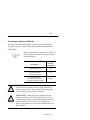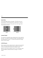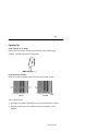
1
Allen-Bradley
Hand-Held
Undecoded Bar
Code Scanner
Cat. No. 2755-HUG-4,
2755-HUG-9
User
Manual
Important User Information
Because of the variety of uses for the products described in this publication,
those responsible for the application and use of this control equipment must
satisfy themselves that all necessary steps have been taken to assure that each
application and use meets all performance and safety requirements, including
any applicable laws, regulations, codes and standards.
The illustrations, charts, sample programs and layout examples shown in this
guide are intended solely for purposes of example. Since there are many
variables and requirements associated with any particular installation,
Allen-Bradley does not assume responsibility or liability (to include intellectual
property liability) for actual use based upon the examples shown in this
publication.
Allen-Bradley publication SGI-1.1, Safety Guidelines for the Application,
Installation, and Maintenance of Solid-State Control (available from your local
Allen-Bradley office), describes some important differences between solid-state
equipment and electromechanical devices that should be taken into consideration
when applying products such as those described in this publication.
Reproduction of the contents of this copyrighted publication, in whole or in part,
without written permission of Allen-Bradley Company, Inc., is prohibited.
Throughout this manual we use notes to make you aware of safety
considerations:
!
ATTENTION: Identifies information about practices or
circumstances that can lead to personal injury or death,
property damage or economic loss.
Attention statements help you to:
• identify a hazard
• avoid the hazard
• recognize the consequences
Important:
Identifies information that is critical for successful application and
understanding of the product.
Publication 2755-6.1
Table of Contents
Preface
Intended Audience . . . . . . . . . . . . . . . . . . . . . . . . . . . . . . . . . .
Contents of this Manual . . . . . . . . . . . . . . . . . . . . . . . . . . . . . . .
Related Publications . . . . . . . . . . . . . . . . . . . . . . . . . . . . . . . . .
Laser Warning Symbol . . . . . . . . . . . . . . . . . . . . . . . . . . . . . . . .
Chapter 1
Scanner Features
Scanner Features . . . . . . . . . . . . . . . . . . . . . . . . . . . . . . . . . . .
LED Indicators . . . . . . . . . . . . . . . . . . . . . . . . . . . . . . . . . . . . .
Safety Labels . . . . . . . . . . . . . . . . . . . . . . . . . . . . . . . . . . . . . .
Scanning Ranges . . . . . . . . . . . . . . . . . . . . . . . . . . . . . . . . . . .
Standard Range Scanner (Catalog No. 2755-HUG-4) . . . . . . . .
Extended Range Scanner (Catalog No. 2755-HUG-9) . . . . . . .
Accessories . . . . . . . . . . . . . . . . . . . . . . . . . . . . . . . . . . . . . . .
Chapter 2
P–1
P–2
P–3
P–3
1–2
1–3
1–4
1–5
1–6
1–7
1–8
Connecting and Operating Scanner
Compatible Decoders . . . . . . . . . . . . . . . . . . . . . . . . . . . . . . . .
Scanner Cable . . . . . . . . . . . . . . . . . . . . . . . . . . . . . . . . . . . . .
Connecting the Scanner to a Decoder . . . . . . . . . . . . . . . . . . . . .
Operating the Scanner . . . . . . . . . . . . . . . . . . . . . . . . . . . . . . . .
Spotter Beam . . . . . . . . . . . . . . . . . . . . . . . . . . . . . . . . . . . . . .
Automatic Shutoff . . . . . . . . . . . . . . . . . . . . . . . . . . . . . . . . . . .
Audible Response . . . . . . . . . . . . . . . . . . . . . . . . . . . . . . . . . . .
Operating Tips . . . . . . . . . . . . . . . . . . . . . . . . . . . . . . . . . . . . .
Publication 2755-6.1
2–1
2–2
2–3
2–5
2–6
2–6
2–6
2–7
toc–ii
Chapter 3
Troubleshooting and Maintenance
Troubleshooting the Scanner . . . . . . . . . . . . . . . . . . . . . . . . . . .
Cleaning the Scan Window . . . . . . . . . . . . . . . . . . . . . . . . . . . .
Specifications
Appendix A
Connector Pinouts
Appendix B
European Union Directive Compliance
Appendix C
Glossary
Publication 2755-6.1
3–2
3–4
Preface
Using this Manual
Read this preface to familiarize yourself with the rest of the manual.
This preface covers the following topics:
•
•
•
•
intended audience
chapter contents
laser warning symbol
related publications
Intended Audience
No special knowledge is required to understand this document or to use
the scanner. Undecoded scanners require a decoder. We assume that you
are familiar with the operation and cable inputs to your decoder.
Publication 2755-6.1
P–2
Contents of this Manual
The following table briefly describes the contents of each section.
Chapter
Title
Contents
Preface
Using this Manual
Describes the purpose, background, and scope
of this manual. Also provides a list of related
publications.
1
Scanner Features
Overview of the scanner. Includes read range
charts and description of accessory items.
2
Connecting and Operating
the Scanner
Describes how to connect the scanner to a
decoder. Operating tips are also provided.
3
Troubleshooting and
Maintenance
Provides solutions to the most common
operating problems. Also includes instructions
on cleaning the scan window.
Appendix A
Specifications
Provides physical, electrical and environmental
specifications.
Appendix B
Scanner Connector
Pinouts
Provides scanner pinout signal names and a
brief description of each.
Appendix C
European Union
Compliance Directives
Lists requirements for use of scanner within the
European Union.
Provides definitions for commonly used
terminology.
Glossary
Inside Back
Cover
Publication 2755-6.1
Bar Code Test Symbols
Sample symbols useful for testing the operation
of your bar code system.
P–3
Related Publications
Below is a list of related publications you may need to refer to when
using the scanners.
Publication No.
Title
2755-921
Bar Code Basics
Describes bar code symbologies, equipment, and typical applications.
2755-833
User Manual for
DS/DD Series B Enhanced Decoders
2755-ND010
User Manual for
Single-Head Enhanced Decoder (Catalog No. 2755-DS1A)
2755-ND011
User Manual for
Dual-Head Enhanced Decoder (Catalog No. 2755-DD1A)
2755-2.37
Product Data Sheet for
Bulletin 2755 Gun Adapter (Catalog No. 2755-NC16)
Laser Warning Symbol
Be aware of the following laser caution symbols.
LASER LIGHT
DO NOT STARE INTO BEAM
CLASS 2 LASER PRODUCT
680nm LASER
1.0 MILLIWATT MAX OUTPUT
RAYONNEMENT LASER
NE PAS REGARDER DANS LE FAISCEAU
APPAREIL A LASER DE CLASSE 2
LASER–STRAHLUNG
NICHT IN DEN STRAHL BLICKEN !
LASER KLASSE 2
Publication 2755-6.1
Chapter
1
Scanner Features
This chapter describes the features of the standard and extended range,
undecoded scanners. Included are descriptions of:
• major features
• LEDs
• scanning ranges
• safety labels
• accessories
Publication 2755-6.1
1–2
Scanner Features
The scanners use a low power visible (red) laser diode for scanning. The
trigger turns on the laser which scans a label at approximately 36 scans
per second.
LEDs
Trigger
Cable Connector
The laser beam:
-exits through the scan window
-reflects off the label back through the window
-is detected by a sensor in the scanner
When a label is read, the laser beam is automatically turned off until the
trigger is pressed again. If no label is read, the laser beam automatically
turns off after approximately 3 seconds and remains off until the trigger
is released and pressed again.
Note: The Extended Range Scanner (Catalog No. 2755-HUG-9) has a
two position trigger. The first detent provides a spotter beam and the
second position provides a scan line.
Publication 2755-6.1
1–3
LED Indicators
On the back of the scanner there is a clear window through which two
LEDs are visible.
Green
Red
Green LED = Good Read, indicating that a bar code symbol has been
scanned and decoded. LED remains on until the next scan
(trigger pressed).
Red LED = Scanning, indicating that the laser light is on.
Publication 2755-6.1
1–4
Safety Labels
The scanners use a low power visible laser diode. As with any bright
light source, you should avoid staring directly into the beam.
Momentary exposure to a CDRH Class II laser is not known to be
harmful.
The following figure shows the location of all safety labels as they
appear on the scanner.
LASER LIGHT
DO NOT STARE INTO BEAM
CLASS 2 LASER PRODUCT
680nm LASER
1.0 MILLIWATT MAX OUTPUT
AVOID EXPOSURE
LASER LIGHT IS
EMITTED FROM
THIS APERATURE.
Appears on both sides.
RAYONNEMENT LASER
NE PAS REGARDER DANS LE FAISCEAU
APPAREIL A LASER DE CLASSE 2
LASER–STRAHLUNG
NICHT IN DEN STRAHL BLICKEN !
LASER KLASSE 2
COMPLIES WITH
IEC 825–1:1993/EN 60825
CAUTION – LASER LIGHT WHEN OPEN –
DO NOT STARE INTO BEAM.
ATTENTION – RAYONNEMENT LASER EN
CAS DOUVERTURE. NE PAS REGARDER
DANS LE FAISCEAU
VORSICHT!
LASERSTRAHL, WENN ABDECKUNG GEOEFFNET
Publication 2755-6.1
1–5
Scanning Ranges
The scanners can read bar code symbols at various distances depending
upon the bar code symbol density (width of narrow bars or spaces). The
following table lists the read ranges for both the standard and extended
range scanners.
Minimum
Symbol
Density
Standard Range
(Catalog No. 2755-HUG4)
Inches / Centimeters
Extended Range
(Catalog No. 2755-HUG9)
Inches / Meters
5.0 mil
(.13 mm)
1.25 in to 2.7 in
(3.2 cm to 6.9 cm)
Not Applicable
7.5 mil
(.19 mm)
1.0 in to 7.0 in
(2.5 cm to 17.8 cm)
5.0 in to 11 in
(0.13 m to 0.28 m)
10.0 mil
(.25 mm)
Data Not Available
4.0 to 13 in
(0.10 m to 0.33 m)
15.0 mil
(.38 mm)
Data Not Available
4.0 to 60 in
( 0.10 m to 1.52 m)
20.0 mil
(.51 mm)
1.0 in to 27 in
(2.5 cm to 69 cm)
5.0 to 65 in
(0.13 m to 1.65 m)
40.0 mil
(1.02 mm)
4.5 in to 37 in
(11.4 cm to 94 cm)
14 in to 120 in
(0.36 m to 3.05 m)
55.0 mil
(1.40 mm)
7 in to 50 in
(17.8 cm to 127 cm)
24 in to 156 in
(0.61 m cm to 3.96 m)
70.0 mil
(1.78 mm)
Reflective
Not Applicable
96 in to 276 in
2.43 m to 7.01 m
100 mil
(1.02 mm)
Reflective
Not Applicable
96 in to 420 in
(2.44 m to 10.67 m)
Publication 2755-6.1
1–6
Standard Range Scanner
Catalog No. 2755-HUG4
10 (25.4 cm)
Scan Width
Scanner
7.5 mil
(0.19 mm)
20 mil
(0.51 mm)
40 mil
(1.02 mm)
55 mil
(1.40 mm)
0
10
25
15
38
20
51
25
64
30
76
Distance From Front of Scanner
Publication 2755-6.1
0
5 (12.7 cm)
10 (25.4 cm)
5 mil
(0.13 mm)
5
inches
centimeters 12.7
5 (12.7 cm)
35
89
40
102
50
127
1–7
Extended Range Scanner
Catalog No. 2755-HUG9
50 in (127 cm)
Scan Width
See Inset
Scanner
25 in (63.5 cm)
0
25 in (63.5 cm)
50 in (127 cm)
15.0 mil
(0.38 mm)
20.0 mil
(0.51mm)
40 mil
(1.02 mm)
55.0 mil
(1.40 mm)
70.0 mil Reflective
(1.78 mm)
100 mil Reflective
(2.54 mm)
0
inches
centimeters
50
127
100
254
150
381
200
508
250
635
300
762
350
889
420
1067
Distance From Front of Scanner
Inset
3 in (7.8cm)
Scan Width
1.5 in (3.8 mm)
0
1.5 in (3.8 mm)
3 in (7.8cm)
7.5 mil
(.19 mm)
10 mil
(0.25 mm)
0
inches
centimeters
3
7.6
6
15.2
9
22.9
11
27.9
13
33.0
Publication 2755-6.1
1–8
Accessories
The following accessories are available.
Scanner Cables – Connect scanner to A-B
decoder. See page 2–2 for connections.
• 8 ft. / 2.44 meter
(Catalog No. 2755-HUC-GA1-08)
• 15 ft. / 4.57 meter
(Catalog No. 2755-HUC-GA1-15)
• 20 ft. / 6.1 meter
(Catalog No. 2755-HUC-GA1-20)
Adjustable Stands – Holds scanner at adjustable
angles and heights for hand-free scanner
operation.
• 5 to 18 inch (127 to 457 mm) height
(Catalog No. 2755-HFN-K1)
• 9 to 16 inch (229 to 406 mm) height
(Catalog No. 2755-HFN-K2)
Multi-mount Stand – Rubber-coated, fixed
mount holder for counter or wall mounting.
• (Catalog No. 2755-HFN-K3)
Protective Boot – Heavy canvas boot provides
additional protection for the scanner.
• (Catalog No. 2755-HFN-H1)
Publication 2755-6.1
Chapter
2
Connecting and
Operating Scanner
This chapter describes how to connect and test the operation of the
scanner. Sections include:
• compatible decoding devices
• installing / removing the interface cable
• connecting to a decoder
• operating scanner
Safety
!
ATTENTION: Caution - use of controls or
adjustments or performance of procedures other than
those specified herein may result in hazardous laser
light exposure.
Compatible Decoders
The undecoded scanners are compatible with the following
Allen-Bradley decoders:
• Bulletin 2708-DH5 Attended Workstations
• Multi-Purpose Bar Code WorkStation
(Catalog No. 2755-DH1)
• Single or Dual-Head Enhanced Bar Code Decoder
(Catalog No. 2755-DD1x, -DS1x)
Publication 2755-6.1
2–2
Scanner Cable
The scanner cables connect to the bottom of the scanner handle.
See page 1–8 for lengths available.
Slot for Locking Collar
Connector
Locking Collar
Cable Connector
To attach the scanner cable to the scanner.
1. Pull back the locking collar from the connector.
2. Insert the cable connector into the scanner.
3. Align the tabs on the locking collar with the slots on the handle.
4. Push in and turn the locking collar counterclockwise to lock.
Connector is locked when flat edge of locking collar aligns with the
flat edge of the scanner handle.
Remove a scanner cable by rotating the locking collar clockwise until the
cable can be pulled out of the scanner.
Publication 2755-6.1
2–3
Connecting the Scanner to a Decoder
The scanner interface cable connects to the input port of the decoder.
The following table summarizes the cable and connectors required for
each decoder.
Note: A Gun Adapter (Catalog No. 2755-NC16)
may be required to connect the scanner to some
Series B decoders.
Decoder Type
!
!
2755-NC16
Series B
Gun Adapter
Bulletin 2708-DH5
Attended WorkStations
No
Multi-Purpose
Bar Code WorkStation
(Catalog No. 2755-DH1)
No
Single or Dual-Head
Enhanced Bar Code Decoder
(Catalog No. 2755-DS1A, -DD1A)
Required
ATTENTION: Do not install or remove the scanner
cables or connectors until the power to the scanner and
decoder is turned off. Failure to follow this caution may
result in damage to the scanner or decoder.
ATTENTION: Make sure you use the Series B Gun
Adapter (Catalog No. 2755-NC16, Series B). If you are
ugrading from an earlier version Allen-Bradley hand-held
scanner (such as the 2755-G2 or -G3) which used the
Series A gun adapter, you will need to purchase the series
B gun adapter.
Publication 2755-6.1
2–4
The 2755-NC16 Gun Adapter connects to the decoder input port as
shown below for the Enhanced Decoder, the High Speed Decoder is
similar.
Gun Adapter
Publication 2755-6.1
2–5
Operating the Scanner
1. Check your connections.
• Is the scanner cable securely attached?
• If connecting to a High Speed or Enhanced
decoder, is the Gun Adapter present?
• Is power applied to the decoder?
2. Test the scanner
Aim the scanner at the work
surface and press the trigger.
You should see the red beam
on the work surface, and the
red LED on the back of the
scanner should be on.
3. Scan a label.
Scan a bar code. Adjust the
scanner position so that the scan
beam is centered on the bar
code and overlaps both sides.
When the scanner has read a
symbol:
• You will hear a beep from the
decoder (if enabled).
• The green LED will turn on
and remain on until the next
scan.
Publication 2755-6.1
2–6
Spotter Beam
The Extended Range Scanner (Catalog No. 2755-HUG-9) has a two
position trigger. The first detent turns on a spotter beam. Center the
spotter beam over the center of the symbol or press the trigger all the
way to start the scan beam.
Correct
Incorrect
Automatic Shutoff
The scanner will automatically stop scanning after a bar code symbol has
been read. If no symbol is decoded, the scanner will automatically stop
after approximately 4 seconds. You must release and press the trigger
again to resume scanning.
Audible Response
When scanning a bar code symbol, listen for a single short beep from the
decoder. This beep indicates that the bar code has been successfully
scanned. Some decoders cannot provide an audible response.
Note: You will not hear an audible response if you are using the scanner
with Allen-Bradley unattended decoders (Catalog No. 2755-DS1x,
-DD1x).
Publication 2755-6.1
2–7
Operating Tips
Scan Symbols at an Angle
Do not hold the scanner directly perpendicular to the symbol being
scanned. Hold the scanner at a slight angle.
Scan the Entire Symbol
Hold the scanner so that the scan beam crosses the entire symbol.
Correct
Incorrect
Also as general rule:
• the larger the symbol, the farther away you should hold the scanner.
• hold the scanner closer for symbols that have bars that are close
together.
Publication 2755-6.1
Chapter
3
Troubleshooting and
Maintenance
This chapter describes how to troubleshoot and maintain the scanner.
• troubleshooting chart
• cleaning the scan window
• Allen-Bradley Global Technical Support
Publication 2755-6.1
3–2
Troubleshooting the Scanner
This section provides a list of the most common operating problems, the
probable causes, and suggested corrective actions.
Problem
No Scan Beam.
Probable Cause(s)
1. Decoder not on.
1. Verify that decoder is on.
2. Scan beam has timed out.
2. Normal operation. Release
trigger completely and
scan again.
3. Defective scanner cable.
3. If possible, try another
scanner cable.
4. Defective scanner.
4. If possible, try another
scanner using the same
connections. Contact
Allen-Bradley Global
Support (GTS).
1. Trigger on Extended
Range Scanner is not fully
pressed.
1. Extended Range Scanner
has a 2 position trigger.
The first position is for the
spotter beam. Press the
trigger to the next position
for scanning.
2. Defective scanner.
2. Contact Allen-Bradley
Global Technical Support.
Scan Beam Appears as a Dot
Not a line
Publication 2755-6.1
Corrective Action
3–3
Problem
Scan Beam Present,
Symbols Not Read
Probable Cause(s)
Corrective Action
1. Scanner not held at slight
angle to symbol.
1. Hold scanner at an angle
to the symbol.
2. Scan beam not crossing
entire symbol.
2. Make sure scan beam
crosses every bar or space
on the symbol.
3. Decoder not programmed
to read the type of bar
code you are scanning.
3. Make sure the decoder is
configured for the type of
bar code symbols you are
scanning.
4. Poor quality bar code
symbols.
4. Use the symbols provided
on the inside back cover
for testing.
5. Loose cable connections.
5. Check for loose cable
connections.
6. Gun adapter not being
used.
6. If you are connecting the
scanner to a High Speed
or Enhanced decoder, you
must use a Gun Adapter
(Catalog No. 2755-NC16,
Series B).
Publication 2755-6.1
3–4
Cleaning the Scan Window
You may need to clean the window of the scanner. Carefully clean the
window by first removing loose particles of dirt with clean air. Then use
an optical quality cloth moistened with an optical quality cleaning fluid
for plastic lenses and wipe the window in a single direction (don’t wipe
cloth back and forth across window). Do not leave streaks.
!
!
ATTENTION: Do not use abrasive materials such as
disposable wipes and facial tissue. Do not use solvents like
alcohol or acetone. These materials will damage the
window or the finish on the scanner.
ATTENTION: The scanner has no serviceable parts. Do
not open the housing of the scanner.
A-B Technical Support
If you should require assistance or need additional information on
operating the scanner or Allen-Bradley decoder, contact Allen-Bradley
Global Technical Services (GTS) at (216) 646-6800.
Publication 2755-6.1
Appendix A
Specifications
Optical
Nominal Scan Rate . . . . . . . . . . .
Wavelength (nominal) . . . . . . . . .
Maximum Roll (Skew)
-HUG-4 . . . . . . . . . . . . . . . .
-HUG-9 . . . . . . . . . . . . . . . .
Maximum Pitch
-HUG-4 . . . . . . . . . . . . . . . .
-HUG-9 . . . . . . . . . . . . . . . .
Depth of Field . . . . . . . . . . . . . . .
Print Contrast (Minimum) . . . . . . .
Ambient Light Immunity
Incandescent . . . . . . . . . . . .
Fluorescent . . . . . . . . . . . . .
Sodium Vapor . . . . . . . . . . .
Mercury Vapor . . . . . . . . . . .
33 to 39 scans/second
675 nm (Visible Red)
40_ from normal
10_ from normal
55_ from normal
45_ from normal
See page 1-5
50% absolute dark/light differential
350 ft. candles (3766 lux)
450 ft. candles (4844 lux)
350 ft. candles (3766 lux)
450 ft. candles (4844 lux)
Electrical
Supply Voltage . . . . . . . . . . . . . . 4.8 to 14.0V DC
Current . . . . . . . . . . . . . . . . . . . . 110 mA at 5V DC (typical)
Mechanical
Dimensions
Inches . . . . . . . . . . . . . . . . . 5.0 (L) x 2.8 (W) x 6.3 (H)
Millimeters . . . . . . . . . . . . . . 127 (L) x 71 (W) x 160 (H)
Weight . . . . . . . . . . . . . . . . . . . . 8.5 oz (240 g)
Publication 2755-6.1
A–2
Specifications
Environmental
Operating Temperature . . . . . . . .
Storage Temperature . . . . . . . . . .
Humidity . . . . . . . . . . . . . . . . . . .
Drop Test . . . . . . . . . . . . . . . . . .
-22_ to 122_F (-30_ to 50_C)
-40_ to 140_F (-40_ to 60_C)
5% to 95% (noncondensing)
6ft (1.8 meter) to concrete
Laser Certifications
CDRH . . . . . . . . . . . . . . . . . . . . Class II laser product
IEC 825 . . . . . . . . . . . . . . . . . . . Class 2
Agency Certifications
UL and CUL Listed
CE marked for all applicable directives
Publication 2755-6.1
Appendix B
Scanner Pinout
Connections
Pin #1
Pin #10
Pin
Signal Name
1, 2
Power
Function
Power input (4.8 to 14V DC).
3
Ground
Power and signal ground.
4
Enable
Signal input to power-up the scanner, turn on the laser, turn on
scanning motor.
5
Start of Scan
Sychronizes decode logic with the scanner.
6
Trigger Switch
Connected to trigger switch. This output is grounded when the
switch is pressed.
7
Decode LED
Controls green decode LED.
8
Digitized Bar Pattern Output provides a series of pulses proportional to the widths of
the bar code being scanned.
9
Motor Fail
10
Not Used
Powers down laser if scan motor fails.
Publication 2755-6.1
Appendix C
European Union
Directive Compliance
If the Hand Held Undecoded Scanner is installed within the European
Union or EEA regions and has the CE mark, the following regulations
apply.
EMC Directive
Undecoded Hand-Held Bar Code Scanners
This apparatus is tested to meet EMC Directive 89/336/EEC and Low
Voltage Directive 73/23/EEC using the following standards, in whole or
in part:
• EN 55 022 : 1988
• EN 50 082-1 : 1992
IEC 801.2 : 1988
IEC 801.3 : 1988
IEC 801.4 : 1988
• EN 60 950 : 1992 + A1:1993 + A2:1993
• EN 60 825-1 : 1994
The product described is intended for use in an industrial environment.
Declarations of Conformity
A copy of the Declaration of Conformity is provided on the next page.
This document declares that the scanners conform to the applicable
directives.
Publication 2755-6.1
C-2
Publication 2755-6.1
Glossary
A
ASCII
American Standard Code for Information Interchange. A 7
bit-plus-parity code representing 128 letters, numerals,
punctuation marks, and control characters. It is a standard data
transmission code in the U.S.
B
Bit
Binary digit. One bit is the basic unit of binary information.
Generally, eight consecutive bits compose one byte of data. The
pattern of 0 and 1 values within the byte determines its meaning.
Byte
On an addressable boundary, eight adjacent binary digits (0 and 1)
combined in a pattern to represent a specific character or numeric
value. Bits are numbered from the right, 0 through 7, with bit 0 the
low-order bit. One byte in memory can be used to store one ASCII
character.
C
CDRH
Center for Devices and Radiological Health. A federal agency
responsible for regulating laser product safety. This agency specifies
various laser operation classes based on power output during
operation.
Check Digit
A digit used to verify a correct symbol decode. The scanner inserts
the decoded data into an arithmetic formula and checks that the
resulting number matches the encoded check digit. Check digits are
required for UPC but are optional for other symbologies. Using
check digits decreases the chance of substitution errors when a
symbol is decoded.
Publication 2755-6.1
G–2
Codabar
A discrete self-checking code with a character set consisting of digits
0 to 9 and six additional characters: (- $ : / , +).
Code 128
A high density symbology which allows the controller to encode all
128 ASCII characters without adding extra symbol elements.
Code 3 of 9 (Code 39)
A versatile and widely used alphanumeric bar
code symbology with a set of 43 character types, including all
uppercase letters, numerals from 0 to 9, and 7 special characters (- . /
+ % $ and space). The code name is derived from the fact that 3 of 9
elements representing a character are wide, while the remaining 6 are
narrow.
Code 93
An industrial symbology compatible with Code 39 but offering a full
character ASCII set and a higher coding density than Code 39.
Continuous Code
A bar code or symbol in which all spaces within the symbol are parts
of characters. There are no intercharacter gaps in a continuous code.
The absence of gaps allows for greater information density.
Publication 2755-6.1
G–3
D
Decode
To recognize a bar code symbology (e.g., UPC/EAN) and then
analyze the content of the specific bar code scanned.
Decode Algorithm
A decoding scheme that converts pulse widths into data
representation of the letters or numbers encoded within a bar code
symbol.
Discrete Code
A bar code or symbol in which the spaces between characters
(intercharacter gaps) are not part of the code.
Discrete 2 of 5
A binary bar code symbology representing each character by a group
of five bars, two of which are wide. The location of wide bars in the
group determines which character is encoded; spaces are
insignificant. Only numeric characters (0 to 9) and START/STOP
characters may be encoded.
E
EAN
European Article Number. This European/International version of
the UPC provides its own coding format and symbology standards.
Element dimensions are specified metrically. EAN is used primarily
in retail.
H
Host Computer
A computer that serves other terminals in a network, providing such
services as computation, database access, supervisory programs, and
network control.
Publication 2755-6.1
G–4
I
IEC
International Electrotechnical Commission. This international
agency regulates laser safety by specifying various laser operation
classes based on power output during operation.
Intercharacter Gap
The space between two adjacent bar code characters in a discrete
code.
Interleaved Bar Code
A bar code in which characters are paired together, using bars to
represents the first character and the intervening spaces to represent
the second.
Interleaved 2 of 5
A binary bar code symbology representing character pairs in groups
of five bars and five interleaved spaces. Interleaving provides
for greater information density. The location of wide elements
(bar/spaces) within each group determines which characters
are encoded. This continuous code type uses no intercharacter
spaces. Only numeric (0 to 9) and START / STOP characters
may be encoded.
Publication 2755-6.1
G–5
L
Laser
An acronym for Light Amplification by Stimulated Emission of
Radiation. The laser is an intense light source. Light from a laser is
all the same frequency, unlike the output of an incandescent bulb.
Laser light is typically coherent and has a high energy density.
Laser Diode
A gallium-arsenide semiconductor type of laser connected to a power
source to generate a laser beam. This laser type is a compact source
of coherent light.
P
Parameter
A variable that can have different values assigned to it.
Programming Mode
The state in which a scanner is configured for parameter values. See
SCANNING MODE.
Q
Quiet Zone
A clear space, containing no dark marks, which precedes the start
character of a bar code symbol and follows the stop character.
Publication 2755-6.1
G–6
S
Scanner
An electronic device used to scan bar code symbols and produce a
digitized pattern that corresponds to the bars and spaces of the
symbol. Its three main components are:
1. Light source (laser or photoelectric cell) - illuminates a bar
code.
2. Photodetector - registers the difference in reflected light
(more light reflected from spaces).
3. Signal conditioning circuit - transforms optical detector
output into a digitized bar pattern.
Scanning Mode
The scanner is energized, programmed, and ready to read a bar code.
Scanning Sequence
A method of programming or configuring parameters for a bar code
reading system by scanning bar code menus.
Self Checking Code
A symbology that uses a checking algorithm to detect encoding
errors within the characters of a bar code symbol.
Start / Stop Character
A pattern of bars and spaces that provides the scanner with start and
stop reading instructions and scanning direction. The start and stop
characters are normally to the left and right margins of a horizontal
code.
Symbol
A scannable unit that encodes data within the conventions of a
certain symbology, usually including start/stop characters, quiet
zones, data characters, and check characters.
Symbology
The structural rules and conventions for representing data within a
particular bar code type (e.g. UPC/EAN, Code 39).
Publication 2755-6.1
G–7
U
UPC
Universal Product Code. A relatively complex numeric symbology.
Each character consists of two bars and two spaces, each of which
can be any of four widths. The standard symbology for retail food
packages in the United States.
Publication 2755-6.1
Index
A
Accessories
Protective Boot, 1-8
Scanner Cable, 1-8
Stands, 1-8
Audience, Intended, P-1
G
Global Technical Support, 3-4
Gun Adapter, 2-3
L
Label, Scanning, 2-5
B
Boot, Protective, 1-8
C
Cable, Scanner, 2-2
Certifications, A-2
Laser
Certifications, A-2
Warning Label, 1-4
Warning Symbol, P-3
LEDs
Good Read, 1-3
Location, 1-2
Red, 1-3
Cleaning, 3-4
Contents, Manual, P-2
M
Mechanical Specifications, A-1
D
Decoders, 2-1
Compatible, 2-1
Connecting, 2-3
Supported, 2-3
E
O
Operation, 2-5
Optical Specifications, A-1
P
Electrical Specifications, A-1
Protective Boot, 1-8
Environmental Specifications, A-2
Publication, Related, P-3
F
Features, 1-2
Publication 2755-6.1
I-2
R
Read Range
Extended Range Scanner, 1-7
Standard Scanner, 1-6
Read Ranges, 1-5
Related Publications, P-3
S
Scanner
Cable, 1-8, 2-2
Cleaning, 3-4
Features, 1-2
Operating, 2-5
Pinout Connections, B-1
Testing, 2-5
Troubleshooting, 3-2
Scanner , Read Ranges, 1-5
Scanning
Labels, 2-5
Tips, 2-7
Specifications
Electrical, A-1
Environmental, A-2
Mechanical, A-1
Optical, A-1
Stands, Standard and Adjustable, 1-8
Support, GTS, 3-4
Publication 2755-6.1
T
Technical Support, GTS, 3-4
Telephone No., Technical Support, 3-4
Testing, 2-5
Troubleshooting, 3-2
W
Warning
Laser Light, P-3
Safety Label, 1-4
TEST SYMBOLS
1 2 3 4 5
1 2 3 4 5
Code 128
Code 93
A 1 2 3 4 B
Codabar
A
1
2
3
4
B
Code 39
1
2
3
4
5
Discrete 2 of 5
1 2 3 4 5
EAN 128
1 234567 891019
EAN 13
1234 5670
EAN 8
0 1 23 4 5
Interleaved 2 of 5
1
23456 78901
UPC A
0
123456
UPC E
5
2
Worldwide representation.
Argentina • Australia • Austria • Bahrain • Belgium • Brazil • Bulgaria • Canada • Chile • China, PRC •
Colombia • Costa Rica • Croatia • Cyprus • Czech Republic • Denmark • Ecuador • Egypt • El Salvador •
Finland • France • Germany • Greece • Guatemala • Honduras • Hong Kong • Hungary • Iceland • India •
Indonesia • Ireland • Israel • Italy • Jamaica • Japan • Jordan • Korea • Kuwait • Lebanon • Malaysia •
Mexico • Netherlands • New Zealand • Norway • Pakistan • Peru • Philippines • Poland • Portugal •
Puerto Rico • Qatar • Romania • Russia–CIS • Saudi Arabia • Singapore • Slovakia • Slovenia • South
Africa, Republic • Spain • Sweden • Switzerland • Taiwan • Thailand • Turkey • United Arab Emirates •
United Kingdom • United States • Uruguay • Venezuela • Yugoslavia
Allen-Bradley Headquarters, 1201 South Second Street, Milwaukee, WI 53204 USA, Tel: (1)
414 382-2000 Fax: (1) 414 382-4444
Publication 2755-6.1 – November 1996
Supercedes Publication 2755-6.1 August 1996
October 1995
40062-328-01(B)
Copyright 1996 Allen-Bradley Company, Inc. Printed in USA
1784-6.5.19-RN1