1
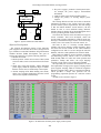
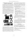
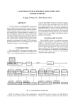
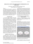
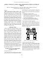
Proceedings of ICALEPCS2003, Gyeongju, Korea
APPLICATIONS OF CANBUS AND CONTROLNET IN EPICS SYSTEM OF
BEPCII
Shifu Xu, Xiangcheng Kong, Qi Le, Jijiu Zhao, IHEP, Chinese Academy of Sciences
P.O.Box 918(10), Beijing 100039, P.R.China
Abstract
BEPC (Beijing Electron Positron Collider) is now
upgrading to the BEPCII. The BEPCII will serve high
energy physics experiments and synchrotron radiation
experiments which consists of a 1.55~1.89GeV linac
accelerator, two transport lines and a 1~2.8GeV storage
ring. The control system will upgrade using the
Experimental Physics and Industrial Control System
(EPICS) system. The CANbus and ControlNet are chosen
as the fieldbuses to communicate between the VME frontend computers and the remote devices. In order to utilize
the CANbus devices of linac control system in BEPC, we
transferred the CANbus EPICS driver to EPICS system of
BEPCII. For some sub-system of BEPCII, we introduced
ControlNet fieldbus and we use Allen-Bradley
programmable logic controller (PLC) as the remote
controller. In this paper, we describe experiences with
CANbus in linac control system of BEPCII and fieldbus
ControlNet in a prototype system.
INTRODUCTION
BEPCII, which will be upgraded from BEPC, consists
of a 1.55~1.89GeV linac accelerator, two transport lines
and a 1~2.8GeV storage ring, which is a double ring
schema [1]. To reach the goal of BEPCII, the current
control system should be upgraded. The new control
system is based on EPICS system, which is noncommercial and open source, and a lot of applications for
accelerator commissioning and operating can be shared
with other laboratories. To meet the budget requirements
of BEPCII, some existing parts should be merged into or
transferred to EPICS system. Before upgrading, the
fieldbus CAN [2] was used to control magnet power
supplies of the linac because of its reliability, ease of use
and wide acceptance and support by industry. In the new
control system of BEPCII, the existing CAN bus devices
are still employed because the EPICS CAN bus device
driver already exists [3]. What needs to be done is
migrating the device driver to the new environment and
developing application software using EPICS tools
To control the vacuum interlock system, injection
power supplies and cryogenic system of BEPCII, the field
bus ControlNet is introduced and Allen-Bradley PLC is
used as the remote controller.
CANBUS IN LINAC POWER SUPPLY
CONTROL SYSTEM
Can Bus Node Device
The CAN bus Node, which is FB remote I/O module, is
custom intelligent device. It provides digital/analog mixed
483
input/output functions, namely 8 channels of analog input
(AD), 4 channels of analog output (DA), 8 channels of
digital input and output (DI & DO). It has the following
features:
• It conforms to CAN2.0A standard.
• Adopting RJ-45 connector is very convenient.
• The digital/analog I/O channels are mixed in a board.
This is suitable for individual device control and
easy for system configuration.
• It can store the max/min readings on board.
• Initial values of DA and DO can be programmed.
• The built-in watch-dog reduces the ratio of failure.
System Architecture before Upgrade
The original power supply control system of linac is
shown in figure 1, which was upgraded from the former
RS232 serial network. A PC’s serial port is connecting to
a RS232/CAN converter. The PC controls the CAN bus
through the converter. Each CAN node can control up to 4
magnet power supplies (PS).
PC
PC
Et her net
RS233/ CAN
PC
CAN_H
CAN_L
CAN
Node 1
PS
PS
…
CAN
Node n
PS
PS
Figure 1: System architecture before upgrade
System Architecture under EPICS
The new power supply control system of linac under
EPICS is shown in figure 2. On EPICS Input/Output
Control (IOC) side, MVME2431 is used as the CPU
board. The IP module TIP810 (version 2.0) is used as
CAN controller module, the IP carrier board is VIPC616.
The former RS232/CAN converter is removed. On EPICS
Operating Interface (OPI) side, SUN workstation running
Solaris 8 or PC running Exceed is used for software
development and machine operating.
Proceedings of ICALEPCS2003, Gyeongju, Korea
OPI
OPI
CPU BOARD: MVME2431
I P: TI P810
I P CARRI ER: VI PC616
Et her net
I OC
CAN_H
CAN_L
CAN
Node 1
PS
PS
…
CAN
Node n
PS
PS
Figure 2: System architecture under EPICS
Software Development
The software development consists of the following
parts: migration of CAN bus device driver, design of new
type of EPICS record, EPICS database design and human
machine interface (HMI) development. The goal of
software development is to get the following functions.
• Monitor the current.
• Mode operation. All the current values of PSs (called
a kind of mode) can be saved and restored for future
use.
• Single PS’s knob and ramping. Adjust individual
power supply. When the setpoint is larger or smaller
than the current value, it should ramp to the setpoint.
• All PSs’ ramping mode. When loading a new mode,
all the power supplies should ramp from the current
values to the setpoints simultaneously.
• The power supply’s parameter’s backup and restore,
for example, the power supply’s online/offline
information.
• CAN bus status can be monitored and reported.
• Change the polarity of steering magnet power
supplies.
The existing EPICS CAN bus device driver should be
transferred according to the custom CAN bus node’s
protocol and the system’s requirements. The main change
is that the EPICS database record instance (.db file)
should be able to access different analog channels.
Another change is that the driver should distinguish the ai
record’s processing and the read back of DA.
To monitor the CAN bus status from OPI, a new type of
record “canstatus” have been developed, which can
provide CAN bus status information, CAN bus node error
messages, transmitted message counter, received message
counter, error event counter, bus off event counter, etc.
The heart of IOC is a memory resident database
together with various memory resident structures. There
are about 620 records resident in IOC. EPICS database
configuration tool VDCT is used to design the real-time
database, which is a multi-platform tool written in JAVA.
EPICS OPI tool EDM is used to build the controlling
and monitoring screens, which is ease to use and can
build friendly HMI. To realise the mode operation and
parameter’s backup and restore, the script language
TCL/TK is used, which is ease to integrated in EDM.
The important part of software development is to meet
the requirements of single power supply’s ramping and all
power supplies’ ramping, which is carried out using State
Notation Language (SNL). SNL is component of EPICS,
which provides a simple and powerful tool for
programming sequential operation in a real-time control
system.
An OPI screen is shown in figure 3.
Figure 3: An OPI screen for linac power supply control system
484
Proceedings of ICALEPCS2003, Gyeongju, Korea
CONTROLNET IN VACUUM CONTROL
SYSTEM AT STORAGE RING
The vacuum system is to maintain the high vacuum of
beam chamber to ensure the positron and electron’s
accelerating and storing in it. The vacuum control system
will control and monitor the following devices: ion
pumps, gauges, valves and temperature sensors, etc. Two
Allen-Bradley ControlLogix PLCs are selected as the
heart of the vacuum protection interlock system, because
ControlLogix is about 8~10 times faster and 30% cheaper
than PLC-5 [4]. The SNS Project has selected the
ControlLogix PLC as the standard PLC [5].
The PLCs are used to monitor vacuum pressure and
gauges interlock outputs and to provide control of the
sector gate valves. The PLCs also output interlock signals
to RF system and other subsystems and receive interlock
signals from other machine protection system (MPS). A
ladder logic program resides and runs in the PLC
processor to control the gate valves on a fail-safe basis.
Based on EPICS, the architecture of vacuum control
system of storage ring is shown below.
OPI
OPI
I P- OCTAL485
I P- OCTAL485
I P- OCTAL232
5136- CN- VME
MVME2431
Ethernet/IP
Et her net
I OC2
I OC1
1756OB16
1756I B16
1756 ENB
1756 CNB
Cont r ol Logi x
5555
Cont r ol Net
CONCLUSION
The field bus CAN and ControlNet have been selected
as the main field buses to control devices in the control
system of BEPCII. CAN bus has been successfully used
in the upgrading of BEPC linac power supply control
system and ControlNet has been tested in a prototype
system. These applications will be helpful for developing
other parts of BEPCII control system.
PLC2
MPS
Val ves
board of ControlNet on IOC is SST 5136-CN-VME.Two
IOCs are planned for vacuum controls of storage ring,
positron and electron rings respectively. The IOC
interfaces directly with vacuum device controllers if the
controllers use serial communication RS232 or RS485,
for example, gauge controller (GC), ion pump controller
(IPC), temperature controller (TC).
The ControlNet needs configuring before running. The
configuration method is as follows:
• Configure and start the SST card according to the
card’s user’s manual.
• Prepare software RSNetworx to configure SST card.
Register new eds file in RSNetworx using EDS
Wizard.
• Configure all the modules of ControlLogix PLC
using software RSLogix5000.
• Configure the produced and consumed tags in
RSLogix5000 for ControlLogix PLC.
• Set up network parameters in RSNetworx, e.g.
Network Update Time (NUT), maximum scheduled
address (SMAX), maximum unscheduled address
(UMAX), etc.
• Use RSNetworx to set up the corresponding
produced and /or consumed connections.
The EPICS device driver for 5136-CN-VME has been
developed [7] and has been tested in the prototype system.
The OPI is developed using EPICS OPI tool EDM, SNL
and TCL/TK. EPICS real-time database is designed using
tool VDCT.
GC
I PC
TC
Gauges
I on
Pumps
Temper at ur e
Sensor s
REFERENCES
.
Figure 4: Architecture of vacuum control system of
storage ring
The ControlNet [6] is selected as the field bus to
exchange data between PLCs. It has high speed,
deterministic and repeatable network features and has
producer/consumer communication model. It can have
redundant media and can remove/insert devices under
power. It is ideal for transmitting time-critical vacuum
system information and providing real-time control. The
communication between IOCs and PLCs can be through
ControlNet, or alternatively Ethernet/IP. The interface
485
[1] http://bipc5.ihep.ac.cn/download/pdr_download.htm
[2] CAN in Automation (CiA), http://www.can-cia.
[3] http://www.aps.anl.gov/asd/people/anj/ipac/
[4] J.Y. Tang, et al. “A Distributed and Collaborative
PLC lab for SNS”, ICALEPCS’99, Trieste, Italy, p370
(1999)
[5] H. C. Hesuh, et al. “Design and Development of the
SNS Ring Vacuum I&C System", PAC'01, Chicago,
USA, p779 (2001)
[6] http://www.controlnet.org/
[7] http://www.sns.bnl.gov/epics/cnet /