1
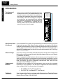
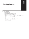
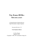
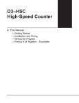
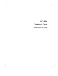
Getting Started
In This Chapter. . . .
— Introduction
— HSC Features
— How Does the HSC Work With the CPU?
— Physical Characteristics & Specifications
— Overview of HSC Inputs and Outputs
— X Input and Y Output Assignments
— Putting It All Together
11
1--2
Getting Started
D4--HSC
Getting Started
Introduction
The Purpose of
this Manual
Thank you for purchasing the High Speed Counter
module for the DL405. This manual shows you how
to install, program, and maintain the equipment. It
also helps you understand the module’s operating
characteristics. Since we constantly try to improve
our product line, we occasionally issue addenda
that document new features and changes to the
products. If an addendum is included with this
manual, please read it to see which areas of the
manual or product have changed.
HIGH SPEED CNTR
TB
CW
OT2
CCW
OT1
PWR
C<P
C=P
C>P
OVR
VE
RST
LTH
RUN
INH
INA
INB
LD1
LD2
D4-HSC
INA
INB
INZ
LD
RST
LATCH
C.INH
RUN
LS1
LS2
L
-V +
CW
L
CCW
L
OUT1
L
OUT2
12/24VDC
1A
Who Should Read
this Manual
If you understand PLC systems, this manual will provide all the information you need
to get and keep your High Speed Counter module up and running. We will use
examples and explanations to clarify our meaning and perhaps help you brush up on
specific features used in the DL405 system. This manual is not intended to be a
generic PLC training manual, but rather a user reference manual for the DL405 High
Speed Counter Module.
Where to Begin
If you are in a hurry and already understand the basics of high speed counters and
basic motion control,you may only want to skim this chapter, and move on to Chapter
2, Installation and Wiring.
Be sure to keep this manual handy for reference when you run into questions. If you
are a new DL405 customer, we suggest you read this manual completely so you can
fully understand the high speed counter module’s configurations and the procedures
used. We believe you will be pleasantly surprised with how much you can
accomplish with PLCDirectä products.
Depending on the products you have purchased, there may be other manuals
necessary for your application. You will want to supplement this manual with any
other manuals written for other products. We suggest:
Supplemental
Manuals
S
S
Technical
Assistance
D4-USER-M (the D4-405 User Manual)
DA-DSOFT-M ( the DirectSOFT User Manual)
If you have questions that are not answered by this manual, our Technical Support
Team is glad to help. They are available from 9:00AM until 6:00PM Eastern Time
Monday through Friday at 800-633-0405.
Getting Started
1--3
1
Getting Started
2
Installation and Wiring
3
Understanding
Operation
4
Setting Up and
Controlling the Count
5
Controlling the Outputs
6
7
Special Features
Applications
includes a brief description of the high speed counter
module, common applications for high speed counters, and
an overview of the steps necessary to setup and operate the
high speed counter.
shows you step-by-step how to install and wire the HSC.
Includes wiring diagrams.
a must for understanding the rest of the manual. It covers the
shared memory concept, the assignment of data types for
the HSC, and how values are stored.
covers offsets and presets, which are needed for many
applications. It provides the programming tools needed to
make full use of the counting capability. It includes count
inhibiting, count latching and overflow flags.
this chapter introduces you to the HSC’s four different control
outputs. It shows you how HSC RUN uses your preset
information and current count to trigger the outputs in an
ordered format. It also covers “manual’ operation of the
outputs without using HSC RUN.
covers two special features that have been built into the
HSC. You will learn about sampling and home search
capabilities.
shows you how to write programs that will provide possible
solutions for some common applications you might
encounter.
Appendices
A
although PLCDirectä does not provide encoders or motor
Introduction to Motor
drives, we have included a brief overview explaining some of
Drives and Shaft Encoders the more common encoders and electronic drives that may
be used with the D4-HSC High Speed Counter.
B
Introduction to Motor
this includes the X and Y data type assignment chart and an
address
map for the seven shared memory parameters.
Drives and Shaft Encoders
Other Resources
You can also check our online resources for the latest product support information:
S Internet -- the address of our Web site is http://www.plcdirect.com
S Bulletin Board Service (BBS) -- call (770) 844--4209
The “note pad” icon in the left-hand margin indicates the paragraph to its immediate
right will be a special note.
The “exclamation mark” icon in the left-hand margin indicates the paragraph to its
immediate right will be a warning or caution. These are very important because the
information may help you prevent serious personal injury or equipment damage.
D4--HSC
Getting Started
Below is a table showing a summary of contents provided within each section of this
manual. The manual is organized into the following seven chapters:
Chapters
1--4
Getting Started
D4--HSC
Getting Started
HSC Features
What is a High
Speed Counter?
Who Needs a High
Speed Counter?
Literally, high speed counters count fast! The D4-HSC high speed counter has one
channel for counting pulses from sensors, encoders, switches, and so on, at rates up
to 100 kHz (50% duty cycle). It is designed to make your job simpler. The HSC has its
own microprocessor that asynchronously counts and accumulates the high speed
pulses. This means the main CPU of the DL405 is free to do the other important
tasks. It can simply check the accumulated count when it needs to do so.
If you have an application that needs to
count pulses rapidly, then you are a
prime candidate for an HSC. The
D4-HSC also has 4 outputs that can be
used for controlling motor speed and
direction. There is one special
requirement. The variable speed motors
or motor drives that are used must be
capable of changing speed when
receiving a voltage input between 10.2
VDC and 26.4 VDC. Many digital drives
being offered today offer programmable
input capability, precisely for this sort of
application.
3 Counting Inputs:
4 Outputs:
CW or CCW
OUT1
INZ
H INB
S
C
CPU
OUT2
INA
drive
encoder
NOTE: The motor control capability should not be confused with a pulse output
capability such as used with stepper motors. The D4-HSC outputs a voltage level
dependent on an external power supply and does not have pulse output
capability. You should check the specs of your drive or motor carefully to make
certain that the specifications of this module match your application requirements.
Types of Counting
Standard Counting
The D4-HSC can do standard UP and DOWN counting or it can do quadrature
counting. These are software selectable as two different modes.
With standard counting you can use the
two counting input signals (INA and
INB)of the D4-HSC. One input is used for
counting UP and the other used for
counting DOWN. You can’t use both
inputs for the same direction of counting.
Standard Counting
Using Two Inputs
One Channel Encoders
UP
INA
INB
You could be using only one of the inputs
if desired. In this case, the other input
terminal should be left unwired. You
control the direction of counting by the
manner in which you set a certain bit in
your control program (shown later).
Standard Counting
Using One Input
INA
DWN
One Channel Encoder
UP or DWN
INB Unused
1--5
Getting Started
Output Control
With quadrature counting, you must use
both signals (INA and INB). Both input
terminals are connected to the same field
device, capable of outputting two square
wave signals, each being offset 90
degrees. Quadrature counting is often
preferred to standard counting because it
can sense direction. Quadrature inputs are
also more noise immune. With quadrature
counting, the direction (UP or DOWN
counting) is determined by whether the
signal being received at INA leads or lags
the signal received at INB. The D4-HSC
looks at the signals coming in and
compares them. It then determines which
is leading and which is lagging. NOTE: We
have not shown the optional use of the
Z-output signal (connected to INZ of the
HSC) that comes standard on most
quadrature encoders. The use of this input
option will be discussed when we cover
resetting the counter externally and the
automatic home search feature.
Quadrature Counting
Quadrature Encoder
INA
INB
Leading and lagging signals
With a rotary encoder, the leading and
lagging signal is determined by which
direction the shaft is turning. This is how
quadrature counting is able to sense
direction.
A typical application for the D4-HSC might be that of having a quadrature type shaft
encoder connected to your motor with the HSC counting and accumulating the pulses
from the encoder as the motor rotates. The HSC knows which way the motor shaft is
turning because it knows which of the two signals being received is leading and lagging.
You can write ladder logic to change either the motor’s speed or direction. (We’ll show
you how to do that a little later!) The D4-HSC provides output signals that can be used to
change speed or direction. Usually these signals are connected to an electronic drive or
motor controller rather than the motor itself. Some motors are “smart” with built-in logic
circuitry for initiating speed and direction changes. In these exceptional cases, the HSC
can be connected directly to the motor to initiate the changes. We leave it up to you to
specify the motor control and thus dictate the load side of the application. Make sure you
check the specs of your motor or motor controller and that you are sure they
match up with the specs of D4--HSC before making any connections.
Pulse Signals In
INA
INB
CW
CW is the clockwise signal output. It is just
one of four possible outputs.
Drive
Level Signal Out
Output Control
Motor
Encoder
D4--HSC
Getting Started
Quadrature
Counting
1--6
Getting Started
D4--HSC
Getting Started
Sampling
Home Search
The HSC can also do sampling over time. That is, you can use simple ladder logic
instructions to indicate the time period for a sampling. When you invoke the sampling
feature of the HSC, it will keep track of the counted pulses for the time period you
have specified and store the total for later RLL retrieval. This is a great feature for
determining frequency of incoming pulses. It’s as simple as specifying a time base,
say 3 seconds, and then counting the pulses for that period. If the HSC sees 6000
pulses during that time span, then you know that you have an incoming pulse rate of
2 kHz (6000/3=2000). There are many other uses for the sampling
feature----frequency counting is just one example.
Many applications require a known starting position for a given work cycle, called
“home point”. This is the point to which the moving piece of apparatus doing the work
(i.e. welder, drill, saw, glue gun, etc.) is returned at the end of each work cycle.
The HSC has an automatic feature that is designed to help find and return to a home
position at the end of each work cycle. You could, of course, write your own home
search RLL. However, the D4-HSC relieves you of that task. Since the algorithm
associated with the automatic home search routine assumes a certain type of
configuration, you will have to make sure that the components and position of each
meets certain specified criteria. Then, you activate the home search using a
Y-output relay. The HSC takes over from there. We’ll show you how to do this later in
this manual.
Work Area Boundaries
Encoder
Drill Head
Home
Point
Motor
Lead Screw
Limit
Switch
LS1
Limit
Switch
LS2
Work Piece
Typical Home Search Setup
HSC
Power Supply
Motor
Controller
Getting Started
1--7
How Does the HSC Work With the CPU?
The diagram below shows you the basic concept. Chapter 4 will cover the subject in
depth.
The CPU and the HSC do not communicate directly.
They do so by exchanging information to and from
the shared memory area, via the CPU’s V-Memory.
Your ladder logic decides what information and when
it is read and written between the two memory areas.
CPU
HSC
V-Memory
Shared
Memory
D4--HSC
Getting Started
Setup Performed
The D4-HSC is an intelligent module that has its own microprocessor and memory.
Via Shared Memory The microprocessor operates asychronously to the DL405 CPU. Its memory area is
called “shared memory”, because both the DL405 CPU and the HSC can read and
write to this area. In fact, that’s how you handle important items like-- telling the
counter your preset value. In this case, you store parameters first in your DL405
CPU’s V-memory area; and then you transfer them to the shared memory area.
Then, the HSC can read and use the information. The HSC microprocessor cannot
read information directly from the DL405’s V-memory area. Likewise, it cannot write
information directly into the CPU’s V-memory area. This is why the two-step process
is always necessary.
1--8
Getting Started
D4--HSC
Getting Started
Physical Characteristics & Specifications
LED Assignments
Label
LED Assignments
HIGH SPEED CNTR
PWR
C<P
C=P
C>P
OVR
Function
PWR
5V POWER ON
C<P
CURRENT COUNT LESS THAN PRESET
C=P
CURRENT COUNT EQUAL TO PRESET
C>P
CURRENT COUNT MORE THAN PRESET
OVR
COUNT OVERFLOW
TB
LOOSE OR MISSING TERMINAL BLOCK
CW
CLOCKWISE OUTPUT ENERGIZED
OUT2
BRAKE (OUT2) OUTPUT ENERGIZED
CCW
COUNTER CLOCKWISE OUTPUT ENERGIZED
TB
CW
OT2
CCW
OT1
INPUT A
INA
INPUT B
INB
OUT1
DECELERATION (OUT1) OUTPUT ENERGIZED
EXTERNAL POWER SUPPLY FOR OUTPUTS FAILED
RST
SIGNAL APPLIED TO RESET INPUT (External Only)
LTH
SIGNAL APPLIED TO LATCH INPUT (External Only)
RUN
SIGNAL APPLIED TO RUN INPUT (External Only)
INH
SIGNAL APPLIED TO INHIBIT CNT INPUT (External Only)
LIMIT SWITCH 1
LS1
INA
SIGNAL APPLIED TO INA INPUT
LIMIT SWITCH 2
LS2
INB
SIGNAL APPLIED TO INB INPUT
SIGNAL APPLIED TO INZ INPUT
LD2
SIGNAL APPLIED TO LD INPUT
INA
INB
LD1
LD2
Terminal Assignments
VE
LD1
VE
RST
LTH
RUN
INH
INZ
LD
INPUT Z
LOAD OFFSET
RESET COUNTER
RST
LATCH COUNT
LATCH
COUNT INHIBIT
C.INH
RUN
HSC RUN
V
L
CLOCKWISE OUTPUT
-+
CW
COUNTER-CLOCKWISE OUTPUT
L
CCW
DECELERATION OUTPUT
L
OUT1
BRAKING OUTPUT
L
OUT2
12/24VDC
1A
EXTERNAL POWER SUPPLY
General Specification
Rating or Requirement
405 CPU Firmware Requirements
Any PLCDirect CPU or other vendor’s 405 CPU (Version 1.6 or later.)
Slot for Installation
Can be installed in any CPU or expansion base.
Cannot be installed in a remote base.
Maximum No. HSC’s per CPU
8
No. of I/O points required
Consumes 16 X-inputs and 32 Y-outputs
Intelligence Source
Has its own microprocessor (operates asynchronously to the DL405 CPU)
Internal Power Consumption
300 mA maximum at 5VDC
Field Wiring Connector
Removable terminal type
Count Signal Level
4.75VDC to 30VDC less than 10mA
Maximum Count Speed
100 kHz (50% duty cycle)
Minimum Input Pulse Width for Counting
5 ms (either state)
Count Input Signal Types
Standard (UP/DOWN) or quadrature (phase differential)
Count Range
--8,388,608 to +8,388,607
Count Direction
UP or DOWN (software selectable or hardwired)
CPU Scan Time Increase per HSC in base
4.2 to 5.5 ms
Getting Started
Counting Inputs (INA, INB, INZ)
1--9
Rating or Requirement
4.75VDC to 30VDC
Maximum Input Current
10 mA
ON Voltage
= 4.75VDC
ON Current
= 5mA
OFF Voltage
= 2.0VDC
OFF Current
= 1.6mA
OFF to ON Delay
= 1.2ms at 5VDC
= 0.8ms at 12VDC
= 0.5ms at 24VDC
ON to OFF Delay
= 1.0ms at 5VDC
= 1.2ms at 12VDC
= 2.5ms at 24VDC
D4--HSC
Getting Started
Input Voltage Range
Control Inputs (LD, LATCH, RST, CINH, RUN, LS1 LS2)
Rating or Requirement
Input Voltage Range
10.2VDC--26.4VDC
Maximum Input Current
10mA
ON Voltage
=10.2VDC
ON Current
=5mA (LD and LATCH); ²4.8mA (RST,CINH,RUN,LS1 and LS2)
OFF Voltage
=4.6VDC (LD and LATCH);
±5.6VDC (RST,CINH,RUN,LS1 and LS2)
OFF Current
=1.6mA (LD and LATCH); ±2mA (RST,CINH,RUN,LS1 and LS2)
OFF to ON Delay
=75ms at 12VDC (LD and LATCH)
=82.5ms at 12VDC (RST,CINH,RUN,LS1 and LS2)
=30ms at 24VDC (LD and LATCH)
=37.5ms at 24VDC (RST,CINH,RUN,LS1 and LS2)
ON to OFF Delay
=240ms at 12VDC (LD and LATCH)
=105ms at 12VDC (RST,CINH,RUN LS1 and LS2)
=260ms at 24VDC (LD and LATCH)
=105ms at 24VDC (RST,CINH,RUN LS1 and LS2)
Control Outputs (CW,CCW,OUT1,OUT2)
Rating or Requirement
Output Power Source
External 10.2VDC--26.4VDC, 1A
Output Type
Open Collector
Maximum Output Current
100 mA per point
Output ON Voltage Drop
= 1.5VDC
Output OFF Leakage Current
= 100mA
Output OFF to ON Delay
= 22.5ms at 12VDC
= 21ms at 24VDC
Output ON to OFF Delay
= 210ms at 12VDC
= 270ms at 24VDC
Built--In Protection
Shut off when output driver IC=175_C (Recovers at 150_C)
Shut off when short (>500mA) is detected (Recovers when short is removed)
Input-pulse-reaching-Preset to internal-signalreaching-Output 1 Time Delay
110ms
1--10
Getting Started
D4--HSC
Getting Started
Overview of HSC Inputs and Outputs
Counting Inputs
INA--Depending on mode chosen, this is either a standard
UP/DOWN counter input, or one of the quadrature counter inputs.
INB--Depending on mode chosen, this is either a standard
UP/DOWN counter input, or one of the quadrature counter inputs.
INZ--This input can be used to help you find home position for
positioning control. It can also be used as an external means of
resetting the counter.
HIGH SPEED CNTR
PWR
C<P
C=P
C>P
OVR
TB
CW
OT2
CCW
OT1
VE
RST
LTH
RUN
INH
INA
INB
LD1
LD2
D4-HSC
Control Inputs
LD--If you want to use an offset number with your counting, a rising
edge signal at this terminal will copy the offset value into the
current count.
RST--A high (ON) signal at this terminal resets the counter to zero
and it remains there until there is a transition to a low signal (OFF).
LATCH -- You may want to store the current count. The rising edge
of a signal at this terminal will store the current count in shared
RAM. Counting continues with no interruption.
INA
INB
INZ
LD
RST
LATCH
C.INH-- You may want to temporarily ignore the count inputs
coming in on INA and INB. A high (ON) signal at this terminal will
inhibit the counting to accomplish this need. Current count is
suspended until a transition to a low (OFF) signal is seen.
RUN--Not to be confused with RUN mode of the DL405,a high
(ON) signal here will activate HSC RUN. A low (OFF) signal will
de-acitivate it.
LS1 or LS2--Either or both of these terminals can be connected to
limit switches to help find home position, or they can merely be
used as discrete inputs.
Control Outputs
C.INH
RUN
LS1
LS2
V
L
-+
CW
L
CCW
L
OUT1
L
OUT2
12/24VDC
1A
CW--You connect the output of this terminal to the appropriate
terminal of your motor controller for clockwise motion when current
count is less than preset and HSC RUN is ON, or when the output
has been turned ON with RLL.
CCW--You connect the output of this terminal to the appropriate
terminal of your motor controller for counter-clockwise motion when
current count is more than preset and HSC RUN is ON, or when
the output has been turned ON with RLL.
OUT1 -- As you approach a target position, you may need to trigger
motor deceleration. A signal from this output can do that. This is
used in the automatic home search algorithm also.
OUT2 -- When you reach your target (current count=preset), you
may need to activate a brake to stop the motor. A signal from this
output can do that.
Y Data Type
Equivalents for
Some Functions
LD, RST, LATCH, C.INH, and RUN all have software equivalents built-in to the logic
of the D4-HSC. These are Y data types that are discussed on the next page. Thus,
you have your choice of either triggering these control inputs externally or
accomplishing essentially the same task internally from within your RLL. They have
been shaded to make them easy to spot.
NOTE: Use external inputs if immediate responses are needed. When a function is
activated through RLL (Y-outputs in this case), the function will not activate until the
I/O update has been performed. This delay is dependent on your CPU’s scanning
speed and the size of your program.
Getting Started
1--11
X Input and Y Output Assignments
X
No.
In this example we have placed the HSC
in slot 0 of the CPU base. This simplifies
X and Y identification because X’s and
Y’s both start at 00.
Xn+0
ON if current count is greater than preset
Xn+1
ON if current count is equal to preset
Xn+2
ON if current count is less than preset
Xn+3
Latched ON if overflow occurs (reset with Ym+1)
Xn+4
Xn+5
Status of CCW output
Status of OUT2 (brake) output
Xn+6
Status of CW output
Xn+7
Xn+10
Status of OUT1 (deceleration) output
Xn+11
Xn+12
Xn+13
H
S
C
IN
OUT OUT
X00-X17
Y00-Y37
For example:
Xn+6=X6=Status of CW output
Ym+3=Y3=ON for HSC RUN
Function
Status of Limit Switch 2
Status of Limit Switch 1
ON if doing a search for home position
ON if a sampling is being conducted
Xn+14
NOT USED
Xn+15
Xn+16
ON for missing terminal block
Y
No.
ON if external power supply for outputs is missing or OFF
Function
Ym+0
ON to reset OUT1 and OUT2 when in HSC run
Ym+1
ON to reset overflow flag (Xn+3)
Ym+2
Rising edge of this signal copies offset value into current count
Ym+3
ON for HSC run
Ym+4
Used to control CCW when not in HSC RUN or Home Search
Ym+5
Used to control OUT2 when not in HSC RUN or Home Search
Ym+6
Used to control CW when not in HSC RUN or Home Search
Used to control OUT1 when not in HSC RUN or Home Search
Ym+7
D4--HSC
Getting Started
There are certain X’s and Y’s reserved by the D4-HSC. By convention, we will be referring to these
assignments as Xn+(z) and Ym+(z) where n and m are offset values based on which slot of the CPU
base you have placed your HSC. The letter z will be some octal number that maps the X or Y to a specific
input or output function. For example if you have the HSC in slot 0, and are using automatic addressing,
then m and n will both be equal to zero. In such case, the data type assignments would be as shown
below. All of this is explained in great detail in Chapter 4. You will also at that time be given a complete
table of the X and Y assignments.
1--12
Getting Started
D4--HSC
Getting Started
Putting It All Together
Up to this point, we have given you only the very basic information about the HSC
module. The six chapters that follow will give you the additional information you need
to make full use of the HSC. There are five basic steps for using the HSC.
Five Steps for
Using the HSC
The Next Chapter
Document Install the Module and Connect the Wiring — Chapter Two
Document Understand How the Module Maps into the I/O Points, and
How the Setup Information is Stored — Chapter Three
Document Setup the Counting and Control Input Parameters —
Chapter Four
Document Setup the Control Outputs — Chapter Five
Document Setup Any Special Features, Such as Home Search or
Sampling — Chapter Six
The next chapter will walk you through the installation and wiring before moving you
on to Step 2.