1
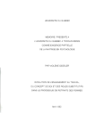
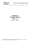
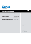
AC 2008-283: EXPERIMENTS AND RESEARCH ACTIVITIES IN A
MICROCONTROLLER LABORATORY
Rafic Bachnak, Texas A&M International University
Dr. Bachnak is Professor of Systems Engineering at Texas A&M International University. He
received his B.S., M.S., and Ph.D. degrees in Electrical and Computer Engineering from Ohio
University in 1983, 1984, and 1989, respectively. Prior to joining TAMIU in 2007, Dr. Bachnak
was on the faculty of Texas A&M-Corpus Christi, Northwestern State University, and Franklin
University. His experience includes several fellowships with NASA and the US Navy
Laboratories and summer employment with Koch Industries. Dr. Bachnak is a registered
Professional Engineer in the State of Texas, a senior member of IEEE and ISA, and a member of
ASEE. He is currently the Vice Chair of the Instrumentation Division of ASEE.
Ramya Chakinarapu, Texas A&M Corpus Christi
Ramya Chakinarapu received her MS degree in Computer Science from Texas A&M
University—Corpus Christi in December 2006. Ramya’s interest includes programming
languages and microprocessor systems. Ramya is currently employed by Avenir Associates, Inc.,
Piscataway, NJ.
Page 13.595.1
© American Society for Engineering Education, 2008
Experiments and Research Activities in a Microcontroller Laboratory
Abstract
This paper describes the activities in a microcontroller laboratory where students learn
programming microcontrollers by carrying out experiments that provide a hands-on
experience with electronics hardware and instruments. The paper will also provide
details of a research project that involves the development of a prototype that takes in an
analog National Television System Committee (NTSC) video signal, generated by a
video camera, and data acquired by a microcontroller and display them in real-time on a
digital panel. An 8051 microcontroller is used to acquire power dissipation by the
display panel, room temperature, and camera zoom level. The paper will present the
major hardware components and show how they are interfaced into a functional
prototype. Test data results are presented and discussed.
Introduction
Computer science and engineering curricula often include a course that covers assembly
language programming. A typical assembly language course includes writing programs
and software simulation involving microprocessors, microcontrollers, or embedded
systems1-3. This paper describes experiments and research activities in a laboratory that
provides interdisciplinary educational and research capabilities in several science and
engineering areas. These areas include systems analysis and design, optimization and
prototyping, hardware-software co-design, re-configurable architectures, peripheral
simulation, modular design and integration, timing and state analysis, multi-layer board
applications, mixed-signal simulation and design, system modeling and algorithm
development, digital design methods, interfacing, and the use of microcontrollers as
basic building blocks in data acquisition and control applications. The rest of this paper
briefly describes the laboratory equipment, discusses the experiments that were
developed to support teaching a microcontroller course, and describes a recently
completed graduate research project.
Laboratory Equipment
Page 13.595.2
Computers, logic analyzers, development boards, and software form a basic set of tools
required to teach advanced digital design techniques and microprocessor-based systems.
In addition, electronic instruments such as power supplies, function generators, digital
multimeters, and oscilloscopes must be available to allow the integration of hardware
and software in an environment that addresses real world applications. The laboratory
consists of twelve workstations and supports a class of 24 students4, 5. The lab also has
more than 15 microcontroller development boards from PHYTEC (microMODUL-8051,
Part #: KMM-207-C04) that has the following features and parts: 12 MHz, AC adapter,
user’s manual, and circuit diagram. PHYTEC custom builds Single Board Computers
(SBCs) in various sizes and configurations and provides development kits for them6,7.
The SBC is plugged into a socket on the development board for programming and
testing. Once the development stage is finished, the SBC can be removed from the
development board and plugged into a socket or soldered to the user’s hardware
application. The serial cable allows connecting the board to a PC for programming,
debugging, and testing.
The software development tools include the PK51 Developer’s Kit are: µVision3 for
Windows™, the C51 ANSI Optimizing C Cross Compiler, the A51 Macro Assembler,
the BL51 Linker/Locator, the LIB51 Library Manager, the OH51 Object-HEX
Converter, and the RTX-51 Real-time Operating System8. The oVision2 IDE allows
managing and developing projects in a cohesive windowed environment. With the
oVision2 integrated environment, the compiling, assembling, and linking can be done in
one step.
Teaching Activities
The laboratory is used to teach a microprocessor and microcontroller course where
students learn assembly language programming by carrying out hands-on experiments
by programming the 8051 microcontroller9. Ten exercises were developed and are
described below.
Software-Only Exercises
Exercise 1: The purpose of the exercise is to introduce students to the microcontroller
board and software development tools by having them build a simple project, which
moves a value into the registers r1 and r2, using the widely used instruction mov source,
destination. Project development includes creating the project code, building the
executable file and debugging it.
Exercise 2: The main objective of this lab is to provide students with an in-depth
knowledge of the build and debug process. In the process students study and understand
the implications of .lst file which is result of the translation or assembly of the project
code (the first step of build process). Students also get familiar with some assembler
directives such as DB and EQU.
Exercise 3: This exercise introduces looping and control transfer. The exercise allows
students to experiment with modular programming by constructing and using a delay
routine. The exercise also familiarizes students with the CALL instruction, conditional
and unconditional jump instructions, and the proper use of the stack.
Exercise 5: This exercise familiarizes students with the 8051 addressing modes. The
program consists of a procedure that moves a string stored at a specific address into
memory starting at another specific memory location. Students monitor execution
results by viewing RAM and ROM memory windows. The program also illustrates the
importance of RET statement that transfers the control back to the main program.
Page 13.595.3
Exercise 6: The exercise involves writing a program to solve an equation that calculates
the position of an object from free fall, given the initial position and time of travel.
Constant definition and memory allocation for variables and result is used. The equation
applies all the arithmetic instructions available in the 8051.
Exercises that Include Hardware
Exercise 4: This exercise involves working with the microcontroller board and the
bread board apart from coding. Students start working with the interface ports of the
8051 chip by configuring ports as input or output and observing data as it is inputted or
outputted. The exercise involves downloading the code to the 8051 board, building a
circuit on a breadboard, and experimenting with data input and output. Students use an
inverter chip, resistors, and LEDs. The input is simulated through the use of a DIP
switch while the output is simulated by using LEDs.
Exercise 7: The exercise involves writing a program that monitors the first six pins of
port1 by connecting LEDs to each pin. Then each pin is set high in a sequence and once
all the pins are on high, it goes clearing each pin in sequence making them off again.
This sequence continues indefinitely. In order for a human eye to visualize the effect
(LED ON and OFF) some delay has to be introduced after each possible instruction in
the program. This is done using one of the timers, timer 0 in mode 1, to create a delay.
Students construct a circuit on a breadboard and use LEDs to illustrate the proper
operation
Exercise 8: The purpose of this exercise is to illustrate the applications of interrupts.
Students write a program that consists of an input and output operations. A low
activated external hardware interrupt o (INT0) is programmed such that it normally
receives a high. When a low is applied to that pin causing an interrupt to occur, a buzzer
is made to emit sound. This is simulated by connecting INT0 pin to a SPDT (SW2)
switch and a buzzer to pin 5 of port 1. The input and output operations are simulated
using DIP switches and LEDs, respectively. The interrupt is caused by a switch that
sounds a buzzer. Students build the circuit and experiment to verify the proper
operation.
Page 13.595.4
Exercise 9: This exercise involves creating and executing a program to understand the
Analog-to-Digital Interfacing capabilities of the C504 Microcontroller. Students explore
the A/D conversion capability of the Infineon C504. This microcontroller has an onboard 10-bit analog to digital converter. The A/D converter is connected to a voltage
source through a potentiometer so that the input voltage can be varied from 0 to 5V.
The A/D converter reads the input voltage and returns a discrete value that corresponds
to the current voltage level. LEDs are connected to the digital outputs from the
microcontroller to indicate the current voltage level. The program compares the voltage
value against 5 discrete voltage ranges. The number of LEDs that turn on depends on
which of these ranges the voltage value fits in. For example, when the voltage is
between 0-1V all LEDs are off. From 1-2V, one LED turns on. From 2-3V, 2 LEDs are
on…etc. The number of LEDs that are on is a representation of the amount of voltage
being fed into the A/D converter. Since the A/D converter has a 10-bit resolution, the
analog input voltage ranging from 0-5V will translate to a digital range of values from 01023. The calculations to find the voltage per step are shown below.
steps
10-Bit Resolution: 2 n / 1 = 210 / 1 ? 1023
*Vmax / Vmin + *5V / 0V +
ÔÕ
· 1000 mV ? 4.89ÃÄ mV
Volts per step:
=
V
step
Å
Ö
# steps
1023
*
+
This means that each digital value or step that is output from the A/D converter
represents 4.89mV. Knowing the amount of voltage that each discrete step represents,
one can calculate the digital value that represents a given voltage. One can also find a
range of discrete values to represent each voltage level. The voltage ranges used for this
lab are shown below:
0<V<1
0 - 203
-- All LEDs OFF
1<V<2
204 - 409
-- One LED ON
2<V<3
410 - 612
-- Two LEDs ON
3<V<4
613 - 817
-- Three LEDs ON
819 - 1009 -- Four LEDs ON
4<V<5
V 5
1010 – 1023 -- Five LEDs ON
The circuit used to test the program is shown in Fig. 1. A 10K potentiometer is used to
vary the input voltage to the A/D converter from 0 to 5 Volts. It is connected between
VCC and ground, with the wiper connected to the A/D input on port P3.2 (pin 34) of the
C504. The reference voltage VAREF is also connected to VCC. The ground reference
VAGND is connected to the common ground. An inverting buffer and 330 Y resistor
are connected between each LED and port 1 of the C504. This is needed because the
C504 cannot source the current to drive the LEDs on its own. As the potentiometer is
adjusted from its minimum to maximum, the LEDs light up indicating the range of
applied voltage to the A/D input.
Fig. 1 Test Circuit for the 8051 A/D Conversion Experiment
Page 13.595.5
Exercise 10: In this exercise, students follow instructions to perform the following tasks:
(a) Removing the PC Power Supply, (b) Removing the PC floppy disk drive, (c)
Removing the major components of a PC, (d) Locating and identifying features of the
microprocessor, math co-processor, RAM, and ROM on the motherboard, (e)
Assembling the PC to its original condition.
Research Activities
The laboratory was used recently to design and developing a Video Conversion and
Data Overlay system. The system takes in an analog National Television System
Committee (NTSC) video signal coming from an analog video camera and parametric
data transmitted serially by a microcontroller. Data obtained is overlaid onto the NTSC
video signal generating a composite video signal, which is converted to digital video
signal and displayed on the TFT-LCD display panel. In the design phase, a number of
hardware components were identified and interface circuits were designed to build a
fully operational system. As a part of the development phase, an 8051 microcontroller
has been programmed to allow overlaying text data on the native video images. The text
overlaid constitutes three user parameters which include power dissipated by the
display, temperature value in degrees Fahrenheit, and camera zoom level. Signal
conditioning circuits have been developed to amplify the captured data signals before
feeding them to the controller.
This project interfaces the analog NTSC video camera with the TFT-LCD display
through a “black box” as illustrated in Figure 2. The black box allows for analog NTSC
video signal capture, parametric data capture, overlay of the captured data and NTSC-todigital conversion of the video. The black box accepts two inputs, the NTSC video
signal coming from the CCD camera and the serial data transmitted by an 8051, and
produces the final digital video signal with the text data overlaid.
Figure 2. Interfacing a CCD Camera with TFT-LCD Panel
Page 13.595.6
The black box consists of an overlay module, a single board computer and LCD
interface kit (LCD controller board, backlight inverter and key board) to drive the
display as shown in Fig. 3. The major components of the project constitute a CCD
camera with an analog NTSC video output, intermediate circuitry to perform text
overlay and analog-to-digital conversion of the signal and the LCD (Liquid Crystal
Display) panel to observe the video with the display parameters overlaid on it. It has
been determined to have a microcontroller in the interface circuit to generate the
required text data, an overlay module to allow for text overlay and a LCD controller to
control the display of the LCD panel. It is necessary to generate a serial data signal as
all data destined for the video overlay must be combined into a single stream of ASCII
characters and commands, pursuant to the overlay module control protocol.
Black Box
NTSC Video
Signal
Analog
NTSC
Camera
Digital video signal
with overlaid text
BOB-3
SFD064V
T4 - ADV
8051
Figure 3.1 System Structure
Serial
Camera zoom level
PD064VT4
Display
Power Dissipated
Temperature value
LM34
Temperature
Sensor
Figure 3. System Major Components
The LCD interface kit consists of three components, the LCD controller/driver board,
OSD unit (key board) and an inverter board. The LCD controller is responsible for
converting analog video signal to digital video signal and driving the signal to the
display. The key board has the OSD menu to allow the user control display parameters
such as brightness, contrast, sharpness etc. And the inverter board provides backlight to
light up the display. All these components are stacked up in a package thus providing an
easy-to-use interface to the user. The user just needs to supply the video signal to obtain
a text over video signal displayed on the panel. Figure 4 shows a picture of the final
system.
Page 13.595.7
Figure 4. Final System
The user manual included in the digital media of the project explains how the user can
interact with the developed system. The manual also includes explanation what each
individual file, the source code of the project, is intended to do. This phase of the
project deals with identifying the components that make up the system and determining
the interdependencies among them. The selection of software and programming
language required to program the microcontroller were dependent on the microcontroller
chosen. The following subsections list out the selected hardware components and
software with a brief explanation as to why they were opted.
Conclusion
This paper describes experiments and research activities in a microcontroller laboratory.
The paper also describes a recently completed graduate research project that uses the
laboratory instruments and equipment. This prototype demonstrates the practicality and
usefulness of taking a NTSC video signal and overlaying it over physical parameters
acquired via a 8051 microcontroller.
Acknowledgement
This project is partially supported by NASA award #NCC5-517, NSF-MII award #0330822NSF,
and the NASA Administrator Fellowship Program.
References
1.
2.
3.
4.
5.
6.
7.
8.
9.
Stephen C. Petersen, Alexandra Carey, Richard Hughey, David Meek, “Assembly Language
Curriculum Realignment in Computer Engineering at UCSC,” Proceedings of the 2002 American
Society for Engineering Education Annual Conference & Exposition, Session 2632, June 16-19,
2002, Montréal, Quebec, Canada.
James T. Streib, “Simplified Assembly Language Programming,” The Journal of Computing in
Small Colleges, Volume 16, Number 1, November 2000
Craig Zilles, “SPIMbot: An Engaging, Problembased Approach to Teaching Assembly Language
Programming,” SIGCSE ’05 St. Louis, Missouri, USA, February 23-27, 2005.
R. Bachnak, D. Kar, and H. Shaalan, “Digital Systems Laboratory for Teaching and Research,"
Proceedings of the Annual Conference of the American Society for Engineering Education, CDROM Session 1520, Salt Lake City, Utah, June 2004.
R. Bachnak, “Teaching Microcontrollers with Hands-on Hardware Experiments,” Journal of
Computing Sciences in Colleges, Vol. 20, No. 4, April 2005, pp. 207-213.
C504 Starter Kit Version 1.0 11.96. Siemens AG, Bereich Halbleiter, Marketing
Kommunikation, Balanstra e 73, 81541 München; 1996.
C504 8-bit CMOS Microcontroller User’s Manual 06.96. Siemens AG, Bereich Halbleiter,
Marketing Kommunikation, Balanstra e 73, 81541 München; 1996.
Keil Software, Inc. A51 Assembly and C51 Complier in Topical Indexes, August 2001
http://www.keil.com/support/topics.htm.
The 8051 Microcontroller, 3rd Edition, Kenneth Ayala, Thomson, Delmar Learning, 2005.
Page 13.595.8