1
MIPS® Malta™ Developer’s Kit - Getting
Started
Document Number: MD00051
Revision 01.07
July 1, 2007
MIPS Technologies, Inc.
955 East Arques Avenue
Sunnyvale, CA 94085-4521
Copyright © 2000-2007 MIPS Technologies Inc. All rights reserved.
Copyright © 2000-2007 MIPS Technologies, Inc. All rights reserved.
Unpublished rights (if any) reserved under the copyright laws of the United States of America and other countries.
This document contains information that is proprietary to MIPS Technologies, Inc. ("MIPS Technologies"). Any copying, reproducing, modifying or use of
this information (in whole or in part) that is not expressly permitted in writing by MIPS Technologies or an authorized third party is strictly prohibited. At a
minimum, this information is protected under unfair competition and copyright laws. Violations thereof may result in criminal penalties and fines.
Any document provided in source format (i.e., in a modifiable form such as in FrameMaker or Microsoft Word format) is subject to use and distribution
restrictions that are independent of and supplemental to any and all confidentiality restrictions. UNDER NO CIRCUMSTANCES MAY A DOCUMENT
PROVIDED IN SOURCE FORMAT BE DISTRIBUTED TO A THIRD PARTY IN SOURCE FORMAT WITHOUT THE EXPRESS WRITTEN
PERMISSION OF MIPS TECHNOLOGIES, INC.
MIPS Technologies reserves the right to change the information contained in this document to improve function, design or otherwise. MIPS Technologies does
not assume any liability arising out of the application or use of this information, or of any error or omission in such information. Any warranties, whether
express, statutory, implied or otherwise, including but not limited to the implied warranties of merchantability or fitness for a particular purpose, are excluded.
Except as expressly provided in any written license agreement from MIPS Technologies or an authorized third party, the furnishing of this document does not
give recipient any license to any intellectual property rights, including any patent rights, that cover the information in this document.
The information contained in this document shall not be exported, reexported, transferred, or released, directly or indirectly, in violation of the law of any
country or international law, regulation, treaty, Executive Order, statute, amendments or supplements thereto. Should a conflict arise regarding the export,
reexport, transfer, or release of the information contained in this document, the laws of the United States of America shall be the governing law.
The information contained in this document constitutes one or more of the following: commercial computer software, commercial computer software
documentation or other commercial items. If the user of this information, or any related documentation of any kind, including related technical data or manuals,
is an agency, department, or other entity of the United States government ("Government"), the use, duplication, reproduction, release, modification, disclosure,
or transfer of this information, or any related documentation of any kind, is restricted in accordance with Federal Acquisition Regulation 12.212 for civilian
agencies and Defense Federal Acquisition Regulation Supplement 227.7202 for military agencies. The use of this information by the Government is further
restricted in accordance with the terms of the license agreement(s) and/or applicable contract terms and conditions covering this information from MIPS
Technologies or an authorized third party.
MIPS, MIPS I, MIPS II, MIPS III, MIPS IV, MIPS V, MIPS-3D, MIPS16, MIPS16e, MIPS32, MIPS64, MIPS-Based, MIPSsim, MIPSpro, MIPS Technologies
logo, MIPS-VERIFIED, MIPS-VERIFIED logo, 4K, 4Kc, 4Km, 4Kp, 4KE, 4KEc, 4KEm, 4KEp, 4KS, 4KSc, 4KSd, M4K, 5K, 5Kc, 5Kf, 24K, 24Kc, 24Kf,
24KE, 24KEc, 24KEf, 34K, 34Kc, 34Kf, 74K, 74Kc, 74Kf, 1004K, 1004Kc, 1004Kf, R3000, R4000, R5000, ASMACRO, Atlas, "At the core of the user
experience.", BusBridge, Bus Navigator, CLAM, CorExtend, CoreFPGA, CoreLV, EC, FPGA View, FS2, FS2 FIRST SILICON SOLUTIONS logo, FS2
NAVIGATOR, HyperDebug, HyperJTAG, JALGO, Logic Navigator, Malta, MDMX, MED, MGB, OCI, PDtrace, the Pipeline, Pro Series, SEAD, SEAD-2,
SmartMIPS, SOC-it, System Navigator, and YAMON are trademarks or registered trademarks of MIPS Technologies, Inc. in the United States and other
countries.
All other trademarks referred to herein are the property of their respective owners.
Template: nB1.03, Built with tags: 2B
MIPS® Malta™ Developer’s Kit - Getting Started, Revision 01.07
Copyright © 2000-2007 MIPS Technologies Inc. All rights reserved.
Contents
Section 1: Introduction........................................................................................................................... 5
1.1: Overview of the Malta Development Platform ............................................................................................. 5
1.2: Package Contents ....................................................................................................................................... 5
1.3: Additional Required Hardware (Not Supplied)............................................................................................. 5
1.4: Optional Hardware....................................................................................................................................... 6
1.5: Recommended Software Tools ................................................................................................................... 6
Section 2: Getting Started...................................................................................................................... 7
2.1: Fitting the Core Card ................................................................................................................................... 7
2.2: Jumper Settings........................................................................................................................................... 7
2.3: DIP Switch Settings ..................................................................................................................................... 7
2.4: Wiring It Up.................................................................................................................................................. 8
2.5: Power-up Sequence .................................................................................................................................... 8
Section 3: Developer’s Kit CD-ROM...................................................................................................... 9
3.1: Installing the Developer’s Kit CD-ROM ....................................................................................................... 9
3.2: Accessing CD-ROM Documentation ........................................................................................................... 9
Section 4: Support ................................................................................................................................ 12
Section 5: Regulatory and Integration Information ........................................................................... 13
5.1: EMC........................................................................................................................................................... 13
5.2: Safety ........................................................................................................................................................ 13
Section 6: Installation Safety Instructions ......................................................................................... 14
6.1: Ensure Chassis and Accessory................................................................................................................. 14
6.1.1: Europe.............................................................................................................................................. 14
6.1.2: United States.................................................................................................................................... 14
6.1.3: Canada............................................................................................................................................. 14
Section 7: References .......................................................................................................................... 15
Section 8: Revision History ................................................................................................................. 15
MIPS® Malta™ Developer’s Kit - Getting Started, Revision 01.07
Copyright © 2000-2007 MIPS Technologies Inc. All rights reserved.
3
4
MIPS® Malta™ Developer’s Kit - Getting Started, Revision 01.07
Copyright © 2000-2007 MIPS Technologies Inc. All rights reserved.
1.1 Overview of the Malta Development Platform
1 Introduction
This document describes how to get started with the MIPS Malta™ Board and Development Kit.
1.1 Overview of the Malta Development Platform
The Malta platform provides a standard platform for software development with MIPS32® and MIPS64® processors. The platform is composed of two parts: the Malta Motherboard, which holds the CPU-independent parts of the
circuitry, and one or more CoreLV or CoreFPGA Core boards, which hold the MIPS CPU plus its System Controller
and fast SDRAM memory.
A large number of standard peripheral interfaces are present on the Malta Motherboard, including Ethernet, RS-232
serial ports, USB, IDE/Compact Flash, Floppy disk, and PS/2 keyboard and mouse. These are provided to allow the
quickest possible up-and-running time, while 4 PCI slots and the Audio/Modem Riser connector allow for attachment
of your own specific devices.
To show the operation of the board as a CPU system, the package also includes the MIPS YAMON™ ROM Monitor,
which allows you to communicate with and control the board. All source code for this monitor is included in the
package.
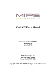
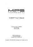
The layout of the Malta board is shown in Figure 1 on page 11.
1.2 Package Contents
The Malta Development Kit contains the following items:
•
This document
•
Malta Board
•
Core Card or CPU Card (type depends on exact configuration ordered)
•
32 MByte (or larger) 3.3V unbuffered PC100 SDRAM module
•
Serial cable for connection to host PC or workstation
•
Parallel male-male conversion Parallel cable for parallel port download to Flash
•
Developers Kit CD-ROM
1.3 Additional Required Hardware (Not Supplied)
In addition to the basic Malta hardware, you will need a suitable standard ATX cabinet with power supply. For a
power supply with standby capabilities, a minimum current of 720 mA is required (1A/1.5A peak recommended) for
the 5V standby voltage.
MIPS® Malta™ Developer’s Kit - Getting Started, Revision 01.07
Copyright © 2000-2007 MIPS Technologies Inc. All rights reserved.
5
1.4 Optional Hardware
The following items may also be useful, depending on your application:
•
Ethernet cable
•
USB cable
•
PS2 Keyboard / mouse
•
IDE cable (40-pin ribbon cable)
•
IDE hard disk
•
Type I or II CompactFlash module (supporting True IDE Mode)
•
Floppy cable (34-pin ribbon cable, 7 wires twisted, PC-style)
•
Floppy drive
For in-depth debugging, the following are useful:
•
HP High-Density Adapter Cables for interface to on-board logic analyzer connectors
•
PCI probe board if you want to be able to monitor activity on the internal PCI bus (e.g., FuturePlus FS2000)
•
Standard Parallel Port Download cable for extending the parallel male-male conversion cable
•
Standard 10 pin header to DB9 converter cable for tty2
If you want to change the SDRAM module, be sure to check the specifications in the User’s Manual for your Core
card, including the CAS latency.
1.5 Recommended Software Tools
A terminal program for communicating with the board via its serial ports will be required. Any workstation or PC
program should work, although performance can vary. MIPS recommends “Procomm Plus32” from Datastorm Technologies for use on a PC.
MIPS works with the leading embedded software and toolchain vendors for support of the Malta board. Refer to the
"Software / Tools" section of the MIPS website (http://www.mips.com) for more information. Upgrades to the
YAMON monitor can also be found at this location.
6
MIPS® Malta™ Developer’s Kit - Getting Started, Revision 01.07
Copyright © 2000-2007 MIPS Technologies Inc. All rights reserved.
2.1 Fitting the Core Card
2 Getting Started
After you have unpacked the kit, check to make sure that you have all the items listed in Section 1.2, "Package
Contents" on page 5. If any items are missing, contact MIPS Technologies.
2.1 Fitting the Core Card
If the Core card has not been mounted on the Malta board, begin by fitting it on the 2, 200-way connectors (J3-J4). It
is aligned and supported with the help of a mounting pillar on each corner. One of the corner mounting pillars is offset to prevent incorrect insertion.
•
Check that any socketed crystals on the Core card are securely in their sockets.
•
Fit the SDRAM module provided in the DIMM socket on the Core card.
•
Mount the Core card. Avoid bending the Malta board.
•
Refer to the appropriate Core Card User’s Manual to check that the jumper settings are correct.
2.2 Jumper Settings
By default, none of the jumpers on the Malta board are fitted.
If a Compact Flash module is used as “Master”, remember to fit JP3 (2 pins), which sets the Compact Flash module as
Master IDE drive on the secondary IDE bus.
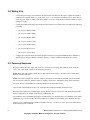
2.3 DIP Switch Settings
Set the DIP switches in the positions shown in Table 1.
A switch is considered ON if any of the following are true:
•
It is in the position marked “ON” on the switch body.
•
It is in the position marked “CLOSED” or not in the “OPEN” position as marked on the switch body.
Table 1
Ref
Settings of DIP Switches
Setting
Notes
S2
All OFF
These switches have no defined function and may be used for any
purpose by the user.
S5
All OFF
Refer to the Malta User’s Manual for the functionality of these
switches. Used to set the endianness of the board.
MIPS® Malta™ Developer’s Kit - Getting Started, Revision 01.07
Copyright © 2000-2007 MIPS Technologies Inc. All rights reserved.
7
2.4 Wiring It Up
•
Connect the power supply (not included) to J8 on the board. Note that some ATX power supplies are unable to
maintain power when the load is very weak. If the “3V3” or “5V” LED turns off without cause or never turns on,
check the power supply. A dummy load can be added to 5V to solve the problem, but the best solution is to get a
good power supply.
•
Connect the included serial cable between the left (tty0) connector of J6 and the host. The cable has the following
pin wiring:
•
•
pin 2 to pin 3 (RXD to TXD)
•
pin 3 to pin 2 (TXD to RXD)
•
pin 4 to pin 6 (DTR to DSR)
•
pin 5 to pin 5 (GND to GND)
•
pin 6 to pin 4 (DSR to DTR)
•
pin 7 to pin 8 (RTS to CTS)
•
pin 8 to pin 7 (CTS to RTS)
Configure the serial port and/or the terminal program on the host. The supplied PROM monitor, YAMON, by
default signs on using 38.4 Kbaud, 8 bits/char, no parity, 1 stop bit, and RTS/CTS hardware flow control.
2.5 Power-up Sequence
When you connect the power supply and switch it on, the board is powered up. Check that the green “ATX ON”,
“3V3”, “5V”, and “STBY” LEDs are on, indicating good power.
NOTE: With some ATX supplies, Malta draws so little current that the supply is not stable. This is technically a
deviation from the ATX spec.
NOTE: The board is brought into “stand-by” mode by pressing the switch marked “ON/NMI” (S4) for more than
four seconds. The “ATX ON” LED is lit when in “stand-by” mode. Press “ON/NMI” to bring up the board again.
The green “FPGA” LED should be on, indicating that the board’s FPGA has booted.
The red “RST” LED should be off. If it is lit, it indicates that something is holding the board in reset.
When the CPU initially boots, YAMON signs-on using the tty0 serial port (the left one) with information about the
board’s configuration, for example, board revision, SDRAM size, etc.
You should now arrive at YAMON’s prompt line. Simultaneously, you should see the word “YAMON” on the ASCII
LED display. If you do not see this, check the YAMON User’s Manual for the meaning of the displayed messages.
Yamon’s help command lists the available commands, and help <command name> gives more detailed information about a specific command.
8
MIPS® Malta™ Developer’s Kit - Getting Started, Revision 01.07
Copyright © 2000-2007 MIPS Technologies Inc. All rights reserved.
3.1 Installing the Developer’s Kit CD-ROM
The board’s default mode is little endian. You can change to big-endian using S5-2,
3 Developer’s Kit CD-ROM
Malta is delivered with a CD-ROM that contains source code and documentation. This may be used on both UNIX
and DOS platforms, though only UNIX directory conventions (“/”) are used in this document. Note that the CD-ROM
also includes files for other boards.
3.1 Installing the Developer’s Kit CD-ROM
Use the following steps to install the Developer’s Kit CD-ROM contents on your workstation/PC:
•
Mount the CD-ROM in the CD-ROM drive.
•
Copy the entire CD-ROM contents to a suitable location in your file system.
3.2 Accessing CD-ROM Documentation
Using a Web browser, open the index.html file in the www directory. This HTML file contains links to all the document files.
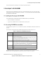
The root directory of the Developer’s Kit CD-ROM contains the directories and files listed in Table 2.
Table 2
Developer’s Kit CD-ROM Root Directories
Directory/File
Contents
docs/
All documentation in PDF format.
yamon/
• Compressed archive of all source files for the YAMON monitor. See the YAMON
Reference Manual for details.
• Binary version for downloading into Flash, should you accidentally erase it. See the
YAMON User’s Manual for details on how to do this.
• Sample application for the Malta board, which can be built and run from YAMON. See
the included README file. Note that no tools are supplied.
linux/
This directory contains both a complete kernel source tree plus pre-compiled kernel and
binary “Userland” to allow you to boot Linux on the Malta board. Refer to the README
file for instructions on how to install and run Linux. Direct support for this Linux installation is not available from MIPS Technologies Inc. - any problems should be addressed in
the usual manner to the Linux open source community mailing lists etc.
www/
Index file to all documentation. Use the index.html file in this directory as a starting
point.
rel_note.txt
Release and revision information for the CD-ROM.
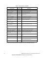
The following documents are found in the docs directory - but note that these are only as up-to-date as the CDROM itself. Refer to the Support pages on the MIPS Web site (http://www.mips.com) for updates.
MIPS® Malta™ Developer’s Kit - Getting Started, Revision 01.07
Copyright © 2000-2007 MIPS Technologies Inc. All rights reserved.
9
Table 3
Document title
Documentation on CD-ROM
Document
number
Description
Malta™ Getting Started
MD00051
This document
Malta™ User’s Manual
MD00048
User’s Manual for the Malta board
Malta™ Schematics
MD00049
Schematics of the Malta board
Malta™ Board Errata / Functional
Change Sheet
MD00050
Errata for Malta
CoreLV™ User’s Manual
MD00007
User’s Manual for the CoreLV board
CoreLV™ Schematics
MD00023
Schematics of the CoreLV board
CoreLV™ Board Errata / Functional
Change Sheet
MD00034
Errata for the CoreLV board
CPU Card (with QED RM5261 Processor) User’s Manual
MD00006
User’s Manual for the RM5261 CPU Card
CPU Card (with QED RM5261 Processor) Schematics
MD00022
Schematics of the RM5261 CPU Card
CPU Card (with QED RM5261 Processor) Errata / Functional Change
Sheet
MD00038
Errata for the RM5261 CPU Card
CoreLV 20Kc™ User’s Manual
MD00057
User’s Manual for the 20Kc CoreLV board.
CoreLV 20Kc™ Schematics
MD00066
Schematics for the 20Kc CoreLV board.
CoreLV 20Kc™ Errata / Functional
Change Sheet
MD00219
Errata for the 20Kc CoreLV board.
Malta™ Developer’s Kit - Getting
Started with Windows® CE.NET™
MD00141
Basic startup instructions for running Windows CE on
Malta.
YAMON™ User’s Manual
MD00008
User documentation for YAMON monitor.
YAMON™ Reference Manual
MD00009
Implementation details for YAMON monitor. This document is intended for the customer wishing to modify
and recompile the YAMON monitor.
YAMON™ Errata Sheet
MD00032
Errata for YAMON monitor.
For detailed documentation on MIPS32™ and MIPS64™ CPU cores, contact MIPS Technologies.
10
MIPS® Malta™ Developer’s Kit - Getting Started, Revision 01.07
Copyright © 2000-2007 MIPS Technologies Inc. All rights reserved.
3.2 Accessing CD-ROM Documentation
Figure 1 Malta Board Layout
J17
J8
J7
J3
J5
JP1
tty0
J6
J9
J1
TX
SPD100
JP3
J19
J18
J21
J31
J20
RST
J22
RESET
S5
5V
1 2 3 4 5 6 7 8
J4
J2
S2
STBY
1 2 3 4
ON/NMI
3V3
ATX ON
J12
J10
FPGA
D28
1 2 3 4 5 6 7 8 9 10
tty1
JP4
J14
J15
JP2
3V
U42
1 2 3 4 5 6 7 8
J13
J16
MIPS® Malta™ Developer’s Kit - Getting Started, Revision 01.07
Copyright © 2000-2007 MIPS Technologies Inc. All rights reserved.
11
4 Support
MIPS Technologies provides support for the Malta product, except the Linux installation, through the following
channels:
12
•
Developer pages at http://www.mips.com. This should be your first call???, in looking for the answer to any
problems or queries you may have. There may be updated versions of the documents available on the site.
•
E-mail hotline. Send an E-mail with your name and company details, plus full details of the hardware and software you have (include revision numbers, serial numbers, and as much other information as possible) to: [email protected]. Remember to include all the details about the problem you are having, such as status of LEDs,
the ASCII LED display, and what has been output on the serial port (tty0).
MIPS® Malta™ Developer’s Kit - Getting Started, Revision 01.07
Copyright © 2000-2007 MIPS Technologies Inc. All rights reserved.
5.1 EMC
5 Regulatory and Integration Information
5.1 EMC
Malta has been designed with EMC requirements in mind but is not tested to any national standards. The user of
Malta is solely responsible for the EMC testing and approval of any derived product.
Under the European EMC Directive (89/336/EEC) and harmonized standards adopted under this Directive for information technology equipment (ITE), Malta is designed and intended to be marketed as an ITE component or module
and not as an ITE apparatus or "printing wiring board assembly" subject to EMC technical standards and the Declaration of Conformity procedures. The user should be fully aware that any product designed using Malta for sale within
the European Economic Area (EEA) is solely responsible for meeting all current EMC regulations.
Under the Part 15 Rules of the Federal Communications Commission (FCC), Malta is designed and intended to be
marketed as a subassembly and not as part of a digital device system subject to FCC technical standards. Any user
product marketed with the Malta subassembly may be subject to FCC technical standards for which the user alone is
responsible.
Under the Industry Canada (IC) standards for digital apparatus set forth in ICES-003, Issue 3, Malta is designed and
intended to be marketed as a digital device subassembly and not as part of a system subject to IC technical standards.
Any product designed and marketed using the Malta subassembly may be subject to IC technical standards for which
the user alone is responsible.
Warning:
This board generates, uses, and can radiate radio frequency energy and, if not installed properly, may cause
interference to radio communications. It has not been tested for compliance with the limits for Class A digital
devices pursuant to FCC, European ,or Canadian standards, which are designed to provide reasonable protection against such interference. Operation of this product in a residential area is likely to cause interference, in
which case the user is required to correct the interference at his/her own expense.
5.2 Safety
Malta is designed to comply with the following safety standards when correctly installed in a chassis that is compatible with such standards:
•
IEC 950 2nd Edition, including Amendments 1, 2, 3 and 4
•
EN 60950 including Amendments 1, 2, 3 and 4 including National Differences
•
UL 1950 Third Edition
•
CSA C22.2, Third Edition
MIPS® Malta™ Developer’s Kit - Getting Started, Revision 01.07
Copyright © 2000-2007 MIPS Technologies Inc. All rights reserved.
13
6 Installation Safety Instructions
Follow these guidelines to meet safety requirements when installing Malta.
Read and adhere to all of these instructions and the instructions supplied with the chassis and power supply. If the
instructions for these components are inconsistent with these instructions contact the vendor’s technical support to
find out how you can ensure that your system meets safety requirements. If you do not follow these instructions and
the instructions provided by the chassis and power supply vendors, you increase the safety risk and possibility of noncompliance with regional laws and workplace safety standards.
6.1 Ensure Chassis and Accessory
Make sure that the chassis, power supply, added subassembly, and internal or external wiring, are certified or otherwise in compliance for the region(s) where the end-product will be used. Marks on the product are proof of compliance and are described in the following subsections.
6.1.1 Europe
The CE marking signifies compliance with all relevant European requirements. If the chassis and power supply does
not bear the CE marking, obtain a vendor’s Declaration of Conformity to the appropriate standards required by European Low Voltage Directive (73/23/EEC). Other directives, such as the Machinery Directive (93/44/EEC) and Radio
and Telecommunications Terminal Equipment Directive (99/5/EC), might also apply depending on the type of product. No regulatory assessment is necessary for low voltage DC wiring used internally or wiring used externally when
provided with appropriate overcurrent protection. Appropriate protection is provided by a maximum 8-A current limiting circuit or a maximum 5A fuse or positive temperature coefficient (PTC) resistor.
6.1.2 United States
A certification or listing mark by a Nationally Recognized Testing Laboratory (NRTL) such as UL, CSA or ETL signifies compliance with safety requirements. External wiring must be NRTL Listed or Recognized as suitable for the
intended use. Internal wiring must be NRTL Listed or Recognized and rated for applicable voltages and temperatures.
6.1.3 Canada
A nationally recognized certification mark such as CSA or cUL signifies compliance with Canadian safety requirements. No regulatory assessment is necessary for low voltage DC wiring used internally or wiring used externally
when provided with appropriate overcurrent protection. Appropriate protection is provided by a maximum 8-A current limiting circuit or a maximum 5A fuse or positive temperature coefficient (PTC) resistor.
14
MIPS® Malta™ Developer’s Kit - Getting Started, Revision 01.07
Copyright © 2000-2007 MIPS Technologies Inc. All rights reserved.
6.1 Ensure Chassis and Accessory
7 References
1.
MIPS Malta™ User’s Manual
MIPS document: MD00048
2.
MIPS Malta™ Schematics
MIPS Document: MD00049
3.
MIPS YAMON™ User’s Manual
MIPS Document: MD00008
4.
MIPS YAMON™ Reference Manual
MIPS Document: MD00009
5.
MIPS CoreFPGA™ 4 User’s Manual
MIPS Document: MD00569
8 Revision History
Change bars (vertical lines) in the margins of this document indicate significant changes in the document since its last
release. Change bars are removed for changes that are more than one revision old.
Revision
Date
Description
01.00
2000/08/30
Initial release
01.01
2000/11/15
Added J31 to layout diagram
01.02
2001/01/17
Layout updated. Power Supply notes added.
01.03
2001/01/25
Layout changed again.
01.04
2001/08/03
Added more precise description of tty0 location.
Removed references to Atlas documents.
New legal text
01.05
2002/01/30
Added information on software tools
01.06
2002/11/19
Added information on extra documentation on CDROM.
01.07
2007/07/12
Updated document with Template nB1.03.
MIPS® Malta™ Developer’s Kit - Getting Started, Revision 01.07
Copyright © 2000-2007 MIPS Technologies Inc. All rights reserved.
15
Copyright © 2000-2007 MIPS Technologies, Inc. All rights reserved.
Unpublished rights (if any) reserved under the copyright laws of the United States of America and other countries.
This document contains information that is proprietary to MIPS Technologies, Inc. ("MIPS Technologies"). Any copying, reproducing, modifying or use of this
information (in whole or in part) that is not expressly permitted in writing by MIPS Technologies or an authorized third party is strictly prohibited. At a
minimum, this information is protected under unfair competition and copyright laws. Violations thereof may result in criminal penalties and fines.
Any document provided in source format (i.e., in a modifiable form such as in FrameMaker or Microsoft Word format) is subject to use and distribution
restrictions that are independent of and supplemental to any and all confidentiality restrictions. UNDER NO CIRCUMSTANCES MAY A DOCUMENT
PROVIDED IN SOURCE FORMAT BE DISTRIBUTED TO A THIRD PARTY IN SOURCE FORMAT WITHOUT THE EXPRESS WRITTEN
PERMISSION OF MIPS TECHNOLOGIES, INC.
MIPS Technologies reserves the right to change the information contained in this document to improve function, design or otherwise. MIPS Technologies does
not assume any liability arising out of the application or use of this information, or of any error or omission in such information. Any warranties, whether
express, statutory, implied or otherwise, including but not limited to the implied warranties of merchantability or fitness for a particular purpose, are excluded.
Except as expressly provided in any written license agreement from MIPS Technologies or an authorized third party, the furnishing of this document does not
give recipient any license to any intellectual property rights, including any patent rights, that cover the information in this document.
The information contained in this document shall not be exported, reexported, transferred, or released, directly or indirectly, in violation of the law of any
country or international law, regulation, treaty, Executive Order, statute, amendments or supplements thereto. Should a conflict arise regarding the export,
reexport, transfer, or release of the information contained in this document, the laws of the United States of America shall be the governing law.
The information contained in this document constitutes one or more of the following: commercial computer software, commercial computer software
documentation or other commercial items. If the user of this information, or any related documentation of any kind, including related technical data or manuals,
is an agency, department, or other entity of the United States government ("Government"), the use, duplication, reproduction, release, modification, disclosure,
or transfer of this information, or any related documentation of any kind, is restricted in accordance with Federal Acquisition Regulation 12.212 for civilian
agencies and Defense Federal Acquisition Regulation Supplement 227.7202 for military agencies. The use of this information by the Government is further
restricted in accordance with the terms of the license agreement(s) and/or applicable contract terms and conditions covering this information from MIPS
Technologies or an authorized third party.
MIPS, MIPS I, MIPS II, MIPS III, MIPS IV, MIPS V, MIPS-3D, MIPS16, MIPS16e, MIPS32, MIPS64, MIPS-Based, MIPSsim, MIPSpro, MIPS Technologies
logo, MIPS-VERIFIED, MIPS-VERIFIED logo, 4K, 4Kc, 4Km, 4Kp, 4KE, 4KEc, 4KEm, 4KEp, 4KS, 4KSc, 4KSd, M4K, 5K, 5Kc, 5Kf, 24K, 24Kc, 24Kf,
24KE, 24KEc, 24KEf, 34K, 34Kc, 34Kf, 74K, 74Kf, 74Kc,1004K, 1004Kc, 1004Kf, R3000, R4000, R5000, ASMACRO, Atlas, "At the core of the user
experience.", BusBridge, Bus Navigator, CLAM, CorExtend, CoreFPGA, CoreLV, EC, FPGA View, FS2, FS2 FIRST SILICON SOLUTIONS logo, FS2
NAVIGATOR, HyperDebug, HyperJTAG, JALGO, Logic Navigator, Malta, MDMX, MED, MGB, OCI, PDtrace, the Pipeline, Pro Series, SEAD, SEAD-2,
SmartMIPS, SOC-it, System Navigator, and YAMON are trademarks or registered trademarks of MIPS Technologies, Inc. in the United States and other
countries.
All other trademarks referred to herein are the property of their respective owners.
Template: nW1.03, Built with tags: 2B
MIPS® Malta™ Developer’s Kit - Getting Started, Revision: 01.07
Copyright © 2000-2007 MIPS Technologies Inc. All rights reserved.