1
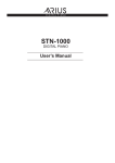
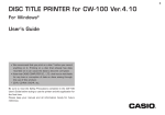
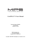
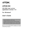
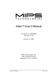
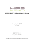
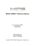
l
CoreLV™ User’s Manual
Document Number: MD00007
Revision 02.06
January 23, 2001
MIPS Technologies, Inc.
1225 Charleston Road
Mountain View, CA 94043-1353
Copyright © 1999-2000 MIPS Technologies, Inc. All rights reserved.
Unpublished rights reserved under the Copyright Laws of the United States of America.
This document contains information that is proprietary to MIPS Technologies, Inc. (“MIPS Technologies”). Any
copying, modifyingor use of this information (in whole or in part) which is not expressly permitted in writing by MIPS
Technologies or a contractually-authorized third party is strictly prohibited. At a minimum, this information is protected
under unfair competition laws and the expression of the information contained herein is protected under federal
copyright laws. Violations thereof may result in criminal penalties and fines.
MIPS Technologies or any contractually-authorized third party reserves the right to change the information contained in
this document to improve function, design or otherwise. MIPS Technologies does not assume any liability arising out of
the application or use of this information. Any license under patent rights or any other intellectual property rights owned
by MIPS Technologies or third parties shall be conveyed by MIPS Technologies or any contractually-authorized third
party in a separate license agreement between the parties.
The information contained in this document constitutes one or more of the following: commercial computer software,
commercial computer software documentation or other commercial items. If the user of this information, or any related
documentation of any kind, including related technical data or manuals, is an agency, department, or other entity of the
United States government (“Government”), the use, duplication, reproduction, release, modification, disclosure, or
transfer of this information, or any related documentation of any kind, is restricted in accordance with Federal
Acquisition Regulation 12.212 for civilian agencies and Defense Federal Acquisition Regulation Supplement 227.7202
for military agencies. The use of this information by the Government is further restricted in accordance with the terms
of the license agreement(s) and/or applicable contract terms and conditions covering this information from MIPS
Technologies or any contractually-authorized third party.
MIPS, R3000, R4000, R5000, R8000 and R10000 are among the registered trademarks of MIPS Technologies, Inc., and
R4300, R20K, MIPS16, MIPS32, MIPS64, MIPS-3D, MIPS I, MIPS II, MIPS III, MIPS IV, MIPS V, MDMX,
SmartMIPS, 4K, 4Kc, 4Km, 4Kp, 5K, 5Kc, 20K, 20Kc, EC, MGB, SOC-it, SEAD, YAMON, ATLAS, JALGO, CoreLV
and MIPS-based are among the trademarks of MIPS Technologies, Inc.
All other trademarks referred to herein are the property of their respective owners.
CoreLV™ User’s Manual, Revision 02.06
Table of Contents
1 Introduction ................................................................................................................................................................4
2 Installation ..................................................................................................................................................................5
3 Description .................................................................................................................................................................6
3.1 CPU ..................................................................................................................................................................6
3.1.1 CPU Power Supply ................................................................................................................................6
3.2 System Controller GT64120 ............................................................................................................................6
3.2.1 Programming Notes ...............................................................................................................................7
3.3 SDRAM ...........................................................................................................................................................8
3.4 CBUS ...............................................................................................................................................................8
3.5 Interrupts ..........................................................................................................................................................9
3.6 JTAG Chain .....................................................................................................................................................9
3.7 Revision Register ...........................................................................................................................................10
4 Testpoints .................................................................................................................................................................12
5 Connectors ...............................................................................................................................................................13
5.1 Logic Analyzer Connectors ...........................................................................................................................13
5.1.1 J6-ODD label “JD3” ............................................................................................................................14
5.1.2 J7-ODD label “JD1” ............................................................................................................................14
5.1.3 J8-ODD label “BUS CTRL1” .............................................................................................................15
5.1.4 J9-ODD label “CPU1” - only in revision 09 and earlier .....................................................................15
6 LEDs ........................................................................................................................................................................16
7 Jumpers ....................................................................................................................................................................18
8 Switches ...................................................................................................................................................................20
9 Clock Circuitry .........................................................................................................................................................21
9.1 CPU Clocking ................................................................................................................................................21
10 PCB Layout ............................................................................................................................................................23
Appendices .........................................................................................................................................................................25
A References ...............................................................................................................................................................25
B Revision History ......................................................................................................................................................25
CoreLV™ User’s Manual, Revision 02.06
3
1 Introduction
1 Introduction
This document is the User’s Manual for the MIPS CoreLV™ card, which is a Core Card designed for use with the MIPS
Atlas™ and other compatible MIPS motherboards. There may be small variations between types dependent on the CPU
fitted - if so they will be documented in this Manual.
The manual is valid for all revisions of the MIPS CoreLV™ card. Revision specific issues are treated in the relevant
paragraphs.
The main difference between revision 09 and earlier and revision 10 and later is that revision 10 and later is based on a
new PCB design. This new PCB design has the following features that differ from the previos one:
• The board has support for the Galileo GT64120A 100MHz system controller.
• A transciever isolates the SDRAM data bus from the CBUS also used on the motherboard, enabling the design to run
at 100MHz.
• The JTAG chain contains the CPU only.
The MIPS CoreLV™ card carries one of the standard LV (Lead Vehicle) implementations of MIPS32 4K™ or MIPS64
5K™ processor cores, see Ref [3]. It provides a standard platform for these cores via its interface to a MIPS motherboard.
The MIPS CoreLV™ card provides:
• A North Bridge chip with PCI interface.
• SDRAM controller (in North Bridge).
• Debug connectors to system busses.
• Clock source for the CPU.
• Interface to MIPS motherboard.
Together with an Atlas™ motherboard the assembly meets the Microsoft® Harp Windows® CE platform specification
for both rack-mounting and standalone operation, see Ref [1] and Ref [2].
Motherboard
Motherboard connectors J3/J4
168 pin SDRAM socket
CBUS
PCI
GT64120
SysAD
Core Lead
Vehicle
EPLD
7064
Conf. jumpers
HP LA debug
Clock
generation
Figure 1 Overview
CoreLV™ User’s Manual, Revision 02.06
4
2 Installation
Before use, the supplied (or other suitable) SDRAM DIMM should be mounted in the socket provided. The keying slots
should be aligned as shown in Figure 6 and Figure 7. Since the modules must be capable of 2-cycle CAS latency and a
burst length of 8 at 100MHz, PC100-2-2-2 modules must be used.
The CoreLV™ card is placed on the motherboard and an asymmetrically-placed mounting pillar on the motherboard
prevents reverse insertion.
CoreLV™ User’s Manual, Revision 02.06
5
3 Description
3 Description
The following features are present on the MIPS CoreLV™ card.
3.1 CPU
The CPU is a MIPS core Lead Vehicle, according to Ref [3]. It interfaces to the System controller via its 64-bit SYSAD
bus.
3.1.1 CPU Power Supply
The CPU power supply is split between the core and the IO sections of the LV chip. There is also a separately decoupled
supply for the internal PLL.
Table 1 Power Supplies
Supply
Voltage
Voltage
test point
Current jumper/resistors
Current measurement
testpoints
In revision 09 and earlier:
Core
1.25 to 2.5V (set by
R134 & R135)
CORE
IO
3.3V
IO
JP4 7-8 & 9-10
In revision 10 and later R175 - 0R1
DXV (+) & CORE (-)
In revision 09 and earlier:
JP4 1-2 & 3-4
In revision 10 and later R176 - 0R1
3V3 (+) & IO (-)
To measure the current to the LV’s Core & IO supplies in revision 09 and earlier of the MIPS CoreLV™ card, remove
the Current Jumpers and connect an ammeter between the two Current Measurement Testpoints, all as specified in Table
1. Do not power the board up without the ammeter in circuit.
In revision 10 and later the two currents are determined by measuring the voltage across the two 0.1 Ohm resistors R175
and R176 as shown in the table above (use the testpoints in the table). A direct current measurement as described for
revision 09 and earlier is also possible if the two resistors are removed. Do not power the board up without the ammeter
or the two resistors in circuit.
3.2 System Controller GT64120
The system controller is a Galileo GT64120. In revision 09 and earlier of the MIPS CoreLV™ card it is a GT64120 that
is used, see Ref [4], and in revision 10 and later it is a GT64120A, see Ref [5]. This system controller is designed to
interface R4000®, R5000® and R7000® MIPS CPUs. The main functions in this device include:
• Host to PCI bridge functionality.
• SDRAM controller and Host to SDRAM interface.
• Device bus interface. The device bus from the GT64120 is modified in the EPLD on the Core card to provide the
CBUS which is used for access to Boot Flash, Flash memory and peripheral devices as DUART, LED’s, switches etc.
placed on the motherboard.
The reset configuration for the GT64120 is sampled on a number of shared pins while reset is asserted. The EPLD U7
drives some of these values - others are controlled by pullup/down resistors.
CoreLV™ User’s Manual, Revision 02.06
6
3 Description
Table 2 GT64120 Boot-Time Configuration
Parameter
PCI bus config.
Value
Only PCI 0 enabled
Endianness
GT address ID
PCI code class select
Multiple GT64120
support
Automatic
2’b11
1
Function
32 bit PCI enabled.
Controlled by endian signal from the motherboard.
Default for boot device. Controlled by pullup.
host bridge. Controlled by pullup.
No
Controlled by pulldown.
66 MHz PCI
Disabled
Controlled by pulldown
I2O support
Disabled
Controlled by pullup.
UMA support
Disabled
Controlled by pullup.
Programming
conditional PCI retry
Disabled
This is controlled from the EPLD.
Expansion ROM enable
Disabled
This is controlled from the EPLD.
Device Boot bus width
32 bit
This is controlled from the EPLD.
Autoload
Disabled
This is controlled from the EPLD.
PCI_1 Power
Management
Disabled
Controlled by pulldown - only in revision 10 and later.
PCI_0 Power
Management
Disabled
Controlled by pulldown - only in revision 10 and later.
Duplicate ALE
Disabled
This is controlled from the EPLD.
Duplicate SDRAM
signals
Disabled
This is controlled from the EPLD.
Bypass PLL
Enabled
Controlled by pulldown - only in revision 10 and later.
3.2.1 Programming Notes
The GT64120 initially powers up in a SYSAD bus mode where it cannot accept so-called “DDD” back-to-back transfers.
As the LV will start using these types of transfer as soon as it starts to run cached, it is essential that the 64120 be
configured to accept these as soon as possible during the initialisation process, before the caches are enabled.
This is done by setting bit 16 (CPU WriteRate) in register 0x000 (CPU Interface Configuration) to “1”.
The GT64120 also should be set to use the BOOTCSN chip select for its entire device bus region. This is done by the
following sequence:
Write 0x0000.0000 to register 0x43c (CS[3] High Decode Address).
Write 0x0000.00f0 to register 0x440 (BootCS Low Decode Address).
Write 0x0000.00ff to register 0x444 (BootCS High Decode Address).
The addresses for the above register writes are (0xBBE0.0000 + <register number>).
CoreLV™ User’s Manual, Revision 02.06
7
3 Description
Note also that due to a bug in the GT64120, in big-endian mode all register contents are effectively byte-swapped, which
should be taken into account in performing the above setups.
3.3 SDRAM
The SDRAM controller can be configured so that PC100 SDRAM DIMM up to a maximum of 128Mbyte will function.
Modules must be capable of 2-cycle CAS latency and a burst length of 8 at 100MHz.
Parity signals are connected and can be used if desired.
The CPU can access the DIMM’s serial PROM through the I2C bus on the motherboard, in order to identify the module
characteristics. The programmable address for the I2C device is selected to 3’b000 in accordance with Ref [1].
Connections between the GT64120 SDRAM controller and the SDRAM socket are as follows:
Table 3 GT64120 SDRAM Connectivity
GT64120
SDRAM DIMM
DAdr[10:0]
A[10:0]
DMAReq2N/DAdr[11]
A[11]
BA0
BA0
DMAReq1N/BA1
BA1
AD[63:0]
D[63:0]
SRASN
RAS
SCASN
CAS
DWrN
WE
SCSN[2]
CS[3:2]
SCSN[0]
CS[1:0]
SDQM[7:0]
DQM[7:0]
ADP[7:0]
CB[7:0]
3.4 CBUS
The CBUS is the motherboards simple bus interface, for access to the boot PROM and other devices where a more direct
access than that available through the PCI bus is required. The CBUS is connected via connector J3.
In order to provide the CBUS protocol, the GT64120 device bus signals are decoded by the EPLD U7, as shown in
Figure 2.
Note that in order to isolate the CD signals on the CPU Card from the CBUS data signals on the motherboard a
transceiver has been introduced on the CPU Card, see figures below:
CoreLV™ User’s Manual, Revision 02.06
8
3 Description
AD[4:2]
DADR[2:0]
BUFFER
CD[31:0]
AD[31:0]
LATCH
ALE
CSN[3:0]
BootCS
CSTiming
RDWRN
READYN
DevRWN
EPLD
AD[25:5]
CWRN
CRDN
CCSN
Figure 2 Revision 09 and Earlier Device Bus to CBUS Conversion
BUFFER
DADR[2:0]
AD[4:2]
CD[31:0]
AD[31:0]
TRANSCEIVER
AD[25:5]
LATCH
ALE
CSN[3:0]
BootCS
CSTiming
RDWRN
READYN
DevRWN
EPLD
CWRN
CRDN
CCSN
Figure 3 Revision 10 and Later Device Bus to CBUS Conversion
3.5 Interrupts
The InterruptN signal from GT64120 is connected to the global motherboard interrupt controller through CINTHIN on
the J3 connector. The PCI interrupt from GT64120 PCI_INTN is not used.
CINTLON is driven inactive.
From the motherboard, the 6 interrupt signals IINTN[5:0] and the NMI signal, INMIN are taken directly to the LV CPU.
3.6 JTAG Chain
A JTAG chain is implemented on the Core card. In revision 09 and earlier the chain can be configured to contain the
CPU only or the CPU and the GT64120. This is illustrated in the figure below.
CoreLV™ User’s Manual, Revision 02.06
9
3 Description
Note that in revision 10 and later the JTAG chain contains the CPU only.
TRSTN
EJTRSTN
J3
MIPS
EJTDI
LV
TDI
TDO
JTGCPU
S
EJTDO
CTDO
GTTDO
2-1Mux
GT
64120
TDI
TCK
TDO
inhibit
JTGCPU
Figure 4 JTAG Connectivity in Revision 09 and Earlier
TRSTN
EJTRSTN
J3
MIPS
EJTDI
TDI
LV
TDO
EJTDO
Figure 5 JTAG Connectivity in Revision 10 and Later
3.7 Revision Register
The CoreLV card has a hard-wired board and revision code which can be read from the REVISION register on the
motherboard.
The CORID field (6 bits) is always 0x01 for CoreLV boards.
The CORRV field (2 bits) is given in the following table:
Table 4 CORRV Revision Field
CoreLV revision
CORRV (2 bits)
02 - 09
0x0
CoreLV™ User’s Manual, Revision 02.06
10
3 Description
Table 4 CORRV Revision Field
CoreLV revision
CORRV (2 bits)
10
0x1
CoreLV™ User’s Manual, Revision 02.06
11
4 Testpoints
4 Testpoints
The following testpoints are fitted.
Table 5 Testpoints
Reference
Silk screen
Function
TP1, 8
D3V3
3.3V
TP2
D5V
5V
TP3, 4, 5
GND
GND
CLK
SYSC
In revision 09 and earlier - The board main clock (to all devices, CPU,
GT64120, SDRAM, EPLD etc.).
In revision 10 and later - As above except the CPU.
TP7
D12V
12V
TP9
CORE
LV core voltage - use together with TP11 for current measurement see Section
3.1.1, "CPU Power Supply".
TP10
IO
LV IO voltage - use together with TP8 for current measurement see Section
3.1.1, "CPU Power Supply".
TP11
DXV
LV core power supply voltage - use together with TP9 for current
measurement see Section 3.1.1, "CPU Power Supply".
TP12
CPUC
The CPU clock - only in revision 10 and later.
TP13
GCLKB
GCLKB output from MIPS LV - only in revision 10 and later.
TP14
D2V5
Core supply to Galileo GT64120A - only in revision 10 and later.
TP6
CoreLV™ User’s Manual, Revision 02.06
12
5 Connectors
5 Connectors
The following connectors are present on the board.
Table 6 Connectors
Label
Type
J1
SMA
Function
External clock source. 50 ohm terminated.
The functionality of this is not defined at the time of writing. See the pin
documentation for ERES[11:0] in the Lead Vehicle specification, see Ref [3].
0.1”
header
J2
In revision 09 and earlier it is a 16 pin header with ERES[11:0],
PM_DTLBMISS(ERESP[12]), PM_DTLBHIT (ERESP[13]) and EJ_DEBUGM
(ERESP[14]).
In revision 10 and later it is a 12 pin header with ERES[11:0].
J3
200-way
Motherboard connector J3 as defined in Ref [1].
J4
200-way
Motherboard connector J4 as defined in Ref [1].
J5
3pin
header
Connector for standard 12V PC fan.
In revision 09 and earlier the pinout is: Pin 1 - 12V, pin 2 - NC, pin 3 - GND.
In revision 10 and later it is a header with lock: pin 1 - GND, pin 2 - 12V, pin 3 - NC.
J6-8
HP LA
J9
HP LA
SYSAD debug connectors. See below for signal allocation.
Debug connector for CPU performance meassurement signals.
This connector is not implemented in revision 10 and later.
10pin
header
J10
JTAG programming connector for EPLD.
5.1 Logic Analyzer Connectors
The card contains 3 HP Logic Analyzer connectors for debugging of the SysAD bus. In revision 09 and earlier there is
however an extra HP Logic Analyzer connector for monitoring of the PM signals. The layout of the three connectors
complies to Ref [2].
Table 7 Debug Connectors
Signal
Function
TCLK
SysAD bus Clock. Up to 50 MHz in revision 09 and earlier, and 100MHz in
revision 10 and later.
SYSAD[63:0]
System Address/Data bus.
SYSCMD[8:0]
System command/Data identifier bus.
SYSCMDP
System command/Data identifier bus parity.
SYSADC[7:0]
System Address/Data parity check.
RELEASEN
Signals that the CPU is releasing the system interface to slave state.
RDRDYN
External agent can accept a processor read.
WRRDYN
External agent can accept a processor write.
CoreLV™ User’s Manual, Revision 02.06
13
5 Connectors
Table 7 Debug Connectors
Signal
Function
VALIDINN
External agent drives valid address or data on SysAD and SysCmd busses.
VALIDOUTN
The CPU is driving valid address or data on SysAD and SysCmd busses.
EXTRQSTN
The system interface is submitting an external request.
RSTN
System reset.
DEBUG[6:0]
Various signals from the 7064 EPLD U7. For debugging.
Each of the HP Logic Analyzer connectors contains a ‘EVEN’ part and a ‘ODD’ part which are labelled individually
according to Ref [2]. Below is the pin layout for each connector.
Pin
5.1.1 J6-ODD label “JD3”
Signal
Pin
Signal
Pin
Signal
Pin
Signal
1
NC
3
GND
5
SYSCLK
7
SYSAD63
9
SYSAD62
11
SYSAD61
13
SYSAD60
15
SYSAD59
17
SYSAD58
19
SYSAD57
21
SYSAD56
23
SYSAD55
25
SYSAD54
27
SYSAD53
29
SYSAD52
31
SYSAD51
33
SYSAD50
35
SYSAD49
37
SYSAD48
Signal
Pin
Signal
Pin
Signal
J6-EVEN label “JD2”
Pin
Signal
Pin
2
NC
4
NC
6
*1 SYSCLK
8
SYSAD47
10
SYSAD46
12
SYSAD45
14
SYSAD44
16
SYSAD43
18
SYSAD42
20
SYSAD41
22
SYSAD40
24
SYSAD39
26
SYSAD38
28
SYSAD37
30
SYSAD36
32
SYSAD35
34
SYSAD34
36
SYSAD33
38
SYSAD32
Signal
Pin
Signal
Pin
Signal
5.1.2 J7-ODD label “JD1”
Pin
Signal
Pin
1
NC
3
GND
5
SYSCLK
7
SYSAD31
9
SYSAD30
11
SYSAD29
13
SYSAD28
15
SYSAD27
17
SYSAD26
19
SYSAD25
21
SYSAD24
23
SYSAD23
25
SYSAD22
27
SYSAD21
29
SYSAD20
31
SYSAD19
33
SYSAD18
35
SYSAD17
37
SYSAD16
Signal
Pin
Signal
Pin
Signal
Pin
J7-EVEN label “JD0”
Signal
Pin
2
NC
4
NC
6
*1 SYSCLK
8
SYSAD15
10
SYSAD14
12
SYSAD13
14
SYSAD12
16
SYSAD11
18
SYSAD10
20
SYSAD9
22
SYSAD8
24
SYSAD7
26
SYSAD6
28
SYSAD5
30
SYSAD4
32
SYSAD3
34
SYSAD2
36
SYSAD1
38
SYSAD0
CoreLV™ User’s Manual, Revision 02.06
14
5 Connectors
Pin
5.1.3 J8-ODD label “BUS CTRL1”
Signal
Pin
Signal
Pin
Signal
Pin
Signal
1
NC
3
GND
5
SYSCLK
7
SYSCMD8
9
SYSCMD7
11
SYSCMD6
13
SYSCMD5
15
SYSCMD4
17
SYSCMD3
19
SYSCMD2
21
SYSCMD1
23
SYSCMD0
25
RELEASEN
27
RDRDYN
29
WRRDYN
31
VALIDINN
33
VALIDOUTN
35
EXTRQSTN
37
SYSCMDP
Pin
Signal
Pin
Signal
Pin
J8-EVEN label “BUS CTRL2”
Signal
Pin
Signal
2
NC
4
NC
6
*1 SYSCLK
8
SYSADC7
10
SYSADC6
12
SYSADC5
14
SYSADC4
16
SYSADC3
18
SYSADC2
20
SYSADC1
22
SYSADC0
24
RSTN
26
DEBUG6
28
DEBUG5
30
DEBUG4
32
DEBUG3
34
DEBUG2
36
DEBUG1
38
DEBUG0
Note: *1 indicates that in revision 10 and later this signal is No connect and in revision 09 and earlier it is as stated.
Pin
1
5.1.4 J9-ODD label “CPU1” - only in revision 09 and earlier
Signal
Pin
Signal
Pin
Signal
NC
3
GND
5
SYSCLK
Pin
7
9
11
13
15
17
19
21
23
25
27
29
31
33
35
37
Pin
2
J9-EVEN label “CPU2” - only in revision 09 and earlier
Signal
Pin
Signal
Pin
Signal
NC
10
Signal
Pin
4
NC
6
SYSCLK
8
12
Reserved
14
dtlb_miss
16
Signal
dtlb_hit
18
instncomplete
20
wtbnomerge
22
wtbmerge
24
jtlb_miss
26
jtlb_hit
28
itlb_miss
30
itlb_hit
32
icache_miss
34
icache_hit
36
dcache_miss
38
dcache_hit
For debugging of the signals to the SDRAM module, it is recommended to use a purpose-build logic analyzer adapter
card, for example the Future Plus FS2320, ‘168-pin SDRAM DIMM Analysis Probe and Extender Card’.
CoreLV™ User’s Manual, Revision 02.06
15
6 LEDs
6 LEDs
The following LEDs are fitted to the board.
Table 8 LEDs in Revision 09 and Earlier
LED
Color
subLED
Function
Marking
8 LEDs connected to PM signals.
0 (left)
D2
Red
PM_DCacheHit
DH
1
PM_DCacheMiss
DM
2
PM_ICacheHit
IH
3
PM_ICacheMiss
IM
4
PM_ITLBHit
TH
5
PM_ITLBMiss
TM
6
PM_JTLBHit
JH
7
PM_JTLBMiss
JM
4 LEDs, 3 connected to PM signals.
0 (left)
D1
D13
Red
PM_WTBMerge
WM
1
PM_WTBNoMerge
WN
2
PM_InstnComplete
IC
3
Reserved
XX
ON when Core card ready to come out of reset.
OK
Green
Table 9 LEDs in Revision 10 and Later
LED
Color
Position
D0
Red
0 (left)
D1
Red
D2
Function
Marking
PM_DCacheHit
DH
1
PM_DCacheMiss
DM
Red
2
PM_ICacheHit
IH
D3
Red
3
PM_ICacheMiss
IM
D4
Red
4
PM_ITLBHit
TH
D5
Red
5
PM_ITLBMiss
TM
D6
Red
6
PM_JTLBHit
JH
D7
Red
7
PM_JTLBMiss
JM
D8
Red
8
PM_WTBMerge
WM
D9
Red
9
PM_WTBNoMerge
WN
D10
Red
10
PM_InstnComplete
IC
D11
Red
11
PM_DTLBHit*
UH
D12
Red
12 (right)
PM_DTLBMiss*
UM
CoreLV™ User’s Manual, Revision 02.06
16
6 LEDs
Table 9 LEDs in Revision 10 and Later
LED
Color
D13
Green
Position
Function
ON when Core card ready to come out of reset.
Marking
OK
Note: * - These functions are only applicable on some MIPS32 4K™ LVs.They are applicable on all MIPS64 5K™ LVs.
CoreLV™ User’s Manual, Revision 02.06
17
7 Jumpers
7 Jumpers
The following jumper headers can be fitted to the board. Those specified for MIPS internal use are not fitted to all
production boards.
Table 10 Board Configuration Jumpers
Jumper
Type
options
default
3 way
ext - onb
onb
In revision 09 and earlier: Switches between external
clock (SMA connector J1) & on board clock sources.
2 way
ext
notfit
In revision 10 and later: Enables external clock (SMA
connector J1). If fitted, the on board clock oscillator in
socket U6 must be removed.
JP2
3 way
norm - pll
norm
For MIPS internal use only.
JP3
2 way
fit-notfit
notfit
For MIPS internal use only.
JP1
JP4
10pin
n/a
Function
Fit
In revision 09 and earlier: These jumpers can be removed
in order to measure current to the LV as follows:
1-2
1-2 & 3-4: IO current.
3-4
7-8 & 9-10: Core current.
7-8
In Rev: 04 these jumper are not implemented, see Section
3.1.1, "CPU Power Supply" for LV current measurement.
9-10
Not implemented in revision 10 and later.
JP5
16pin
n/a
none
fitted
For MIPS internal use only.
JP6
16pin
n/a
none
fitted
For MIPS internal use only.
The table below shows the jumpers used for internal configuration of the MIPS LV. All are not-fitted by default.
CoreLV™ User’s Manual, Revision 02.06
18
7 Jumpers
Table 11 CPU Configuration Jumpers
Jumper
sub
default
Function
1-2
-
Sets clock multiplier factor.
3-4
-
GMULTP[1:0] = (3-4, 1-2).
5-6
notfit
Fit to set CTIMER5P = 0 (disables internal timer).
7-8
notfit
Fit to set CPIPEWRP = 0 (disables pipelined writes over SYSAD
bus).
In revision 09 and earlier: Fit to set C4WBLKP = 0 (disables 4-word,
i.e. 2 doubleword, bursts over SYSAD bus).
JP7
9-10
-
This jumper MUST be fitted as the GT64120 does not support
2-doubleword bursts.
In revision 10 and later: This jumper functionality is inverted.
Default is therefore that the jumper MUST not be fitted as the
GT64120 does not support 2-doubleword bursts.
11-12
notfit
For MIPS internal use only.
15-16
notfit
Reserved
all
notfit
For MIPS internal use only.
13-14
JP8
CoreLV™ User’s Manual, Revision 02.06
19
8 Switches
8 Switches
In revision 09 and earlier there is a 4-way pianokey DIP switch S1 on the board. This is for MIPS internal use only, and
if fitted, should have all switches on the OFF position. In revision 10 and later there is no switch on the board.
CoreLV™ User’s Manual, Revision 02.06
20
9 Clock Circuitry
9 Clock Circuitry
Clocking of both MIPS LV and GT64120 is controlled from a single source. In revision 09 and earlier this source may
be up to 50MHz, the limitation being in the card’s layout rather than in any particular device. In revision 10 and later the
clock may be up to 100MHz.
In revision 09 and earlier jumper J1 selects between an external clock source, attached to connector J8, which is an SMA
connector, terminated with 50 ohms, and the on board clock oscillator U6. In revision 10 and later the jumper enables
the external frequency generator, and the on board oscillator has to be removed from the socket U6 if the jumper is fitted.
The selected source drives, via a buffer circuit, the following:
• MIPS LV CPU.
• System controller.
• SDRAM DIMM.
• EPLD.
• Debug connectors J6, J7, J8 and J9.
Note that J9 is not implemented in revision 10 and later.
Note that the PCI clock is totally independent of this system. It is sourced from the J4 connector and only connected to
the PCI clock input on GT64120.
However, note that the Galileo system controller has a timing requirement that the CPU clock run at least 1 MHz faster
than the PCI clock. This limits the lowest frequency useable to 34 MHz, unless it is possible to slow the PCI clock. This
can be done on some MIPS motherboards.
Note that both 14-pin and 8-pin oscillator modules can be fitted on the card in place of U6. A dashed line shows the
positioning of the 8-pin module.
9.1 CPU Clocking
The input clock for the CPU (GCLKP) is derived either from the onboard oscillator or from an external source connected
to the SMA connector, J1. This clock directly gives the SYSAD bus frequency.
For MIPS64 5K™ CPUs and later versions of MIPS32 4K™ CPUs, the internal core clock frequency is controlled by
the LV’s GMULTP[1:0] signals, which are set by a board default and the two links (1-2, 3-4) on JP7. For MIPS32 4K™
CPUs of RTL version 3.2 and earlier the multiplication factor is fixed at 2.
As this is a complex system, depending on precisely which CPU is fitted, please refer to the appropriate documentation
if altering any of these link settings.
Specific Core card configurations are provided in Table 12. These cards are or will soon be available from MIPS
Technologies (or an authorized manufacturer):
Table 12 Clock Frequencies
CPU
PCB
Rev
Manufacturer / code
Crystal
frequency
[MHz]
Clock
multiplier
factor
Core clock
frequency
[MHz]
MIPS32 4K™
01-04
4Kc™, TI F731940
40
2 (fixed value)
80
CoreLV™ User’s Manual, Revision 02.06
21
9 Clock Circuitry
Table 12 Clock Frequencies
CPU
PCB
Rev
Manufacturer / code
Crystal
frequency
[MHz]
Clock
multiplier
factor
Core clock
frequency
[MHz]
MIPS64 5K™
10+
5Kc™, LSS LJA0004
20*
2 (fixed value)
40
* These board variants require a slower PCI clock from the motherboard. See the appropriate motherboard documentation for how to set this.
CoreLV™ User’s Manual, Revision 02.06
22
10 PCB Layout
10 PCB Layout
This card complies to the standard size as described in Ref [1]. The placement of the major components is illustrated in
the figures below.
Offset from
the other
three holes
J3
J5
J6 debug
J8 debug
J7 debug
PC100
DIMM
J9 debug
D2
J2
3V3
D1
MIPS LV
DXV
JP4
CORE
IO
TOP VIEW
U6
J10
JP6
JP5
Keys
U5
GT64120
JP8
JP7
U7
7064
J4
J3, J4: Samtec MOLC-150-31-x-Q
200 pin (50 x 4) 1.27mm pitch connectors on underside.
Figure 6 CoreLV™ Revision 09 and Earlier Layout
CoreLV™ User’s Manual, Revision 02.06
23
10 PCB Layout
Offset from
the other
three holes
J3
JP3
12V
J5
JP7
JP8
J7 debug
GND
PC100
DIMM
DXV
3V3
CORE
IO
GND
J2
J6 debug
J8 debug
MIPS LV
D0
.
.
.
.
.
.
.
.
D12
TOP VIEW
SYSC
CPUC
GCLKB
Keys
J1
GND
U6
JP2
U5
GT64120
J10
U7
7064
2V5
3V3
5V
J4
J3, J4: Samtec MOLC-150-31-x-Q
200 pin (50 x 4) 1.27mm pitch connectors on underside.
Figure 7 CoreLV™ Revision 10 and Later Layout
CoreLV™ User’s Manual, Revision 02.06
24
A References
Appendices
A References
[1] MIPS Atlas™ User’s Manual
MD00005
[2] Standard Development Board Requirements for Microsoft® Windows® CE.
Version 5.4
[3] MIPS 4K/5K™ Lead Vehicle datasheet
MD00001
[4] Galileo GT64120 datasheet
Version 1.4, Sept. 14 1999
[5] Galileo GT64120A datasheet
Version 1.0, Feb. 29 2000
B Revision History
Revision
01.00
Date
99/12/15
Description
Initial release
Added details of C4WBLK jumper.
01.01
2000/01/13
Added specification of SDRAM CAS latency and burst length.
Added details of TI 4Kc LV.
02.00
2000/02/07
PCB Rev: 04 details added.
02.01
2000/03/10
Added REVISION register field info.
Minor trademark cleanup.
02.02
2000/03/24
Clocking table updated.
Copyright updated.
Removed CSM J25C1 from document.
02.03
2000/05/30
Updated copyright notice.
PCB rev. 04 changed to revision 10.
02.04
2000/07/07
General cleanup with regard to revision 10 functionality.
Added details of 5Kc LSS version.
02.05
2000/11/17
02.06
2001/01/23
Added notice about compatible PCI Clock frequencies.
Document Lauout updated.
CoreLV™ User’s Manual, Revision 02.06
25