1
➪
➪
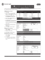
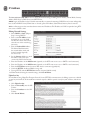
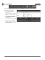
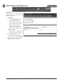
Access Control System
User Programming Guide
Document Number: 620-100240, Rev. E
Notices
It is IMPORTANT that this instruction manual be read and understood completely before installation or
operation is attempted. It is intended that the installation of this unit will be performed only by persons trained
and qualified in the installation of access control equipment. The IMPORTANT safeguards and instructions in
this manual cannot cover all possible conditions and situations which may occur during installation and use. It
must be understood that common sense and caution must be exercised by the person(s) installing, maintaining,
and operating the equipment.
Standards Approvals
This equipment has been tested and found to comply with the limits for a Class A digital device, pursuant
to Part 15 of the FCC Rules. These limits are designed to provide reasonable protection against harmful
interference when the equipment is operated in a commercial environment. This equipment generates, uses, and
can radiate radio frequency energy and, if not installed and used in accordance with the instruction manual, may
cause harmful interference to radio communications. Operation of this equipment a residential area is likely to
cause harmful interference in which case the user will be required to correct the interference at his own expense.
eMerge Access System Installation Contact Information
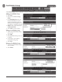
Contents
Log Management . . . . . . . . . . . . . . . . . . .62
Report . . . . . . . . . . . . . . . . . . . . . . . . . . . .63
Access Report . . . . . . . . . . . . . . . . . . . . . .64
System Report. . . . . . . . . . . . . . . . . . . . . .65
Smart Report . . . . . . . . . . . . . . . . . . . . . . .66
Smart Report Setting . . . . . . . . . . . . . . . .67
Card Holder Group . . . . . . . . . . . . . . . . . .73
Door Group . . . . . . . . . . . . . . . . . . . . . . . .74
Camera Group . . . . . . . . . . . . . . . . . . . . . .75
Access Level Group . . . . . . . . . . . . . . . . .76
Client Management . . . . . . . . . . . . . . . . . .77
Client Replacement . . . . . . . . . . . . . . . . . .78
Logout . . . . . . . . . . . . . . . . . . . . . . . . . . . .79
1. Introduction . . . . . . . . . . . . . . . . . . . . . . . .2
General Features . . . . . . . . . . . . . . . . . . . . .2
System Information . . . . . . . . . . . . . . . . . . .2
2. Software Layout . . . . . . . . . . . . . . . . . . . . .3
System Server Software . . . . . . . . . . . . . . .3
Toolbar Menu . . . . . . . . . . . . . . . . . . . . . . . .4
3. System Programming . . . . . . . . . . . . . . .5
Connect to the Controller . . . . . . . . . . . . . .5
Dashboard . . . . . . . . . . . . . . . . . . . . . . . . . .6
Dashboard Setting . . . . . . . . . . . . . . . . . . .7
Camera View . . . . . . . . . . . . . . . . . . . . . . . .8
Camera Setting . . . . . . . . . . . . . . . . . . . . . .9
DVR View . . . . . . . . . . . . . . . . . . . . . . . . . .10
DVR Setting . . . . . . . . . . . . . . . . . . . . . . . .11
Card Holder . . . . . . . . . . . . . . . . . . . . . . . .12
Card Format . . . . . . . . . . . . . . . . . . . . . . .15
Access Level . . . . . . . . . . . . . . . . . . . . . . .16
Badging Layout . . . . . . . . . . . . . . . . . . . . .17
Badging Template . . . . . . . . . . . . . . . . . . .18
Schedule . . . . . . . . . . . . . . . . . . . . . . . . . .19
Holiday . . . . . . . . . . . . . . . . . . . . . . . . . . . .20
Unlock Schedule . . . . . . . . . . . . . . . . . . . .21
One Time Unlock Schedule . . . . . . . . . . .22
Event Action . . . . . . . . . . . . . . . . . . . . . . .23
Event Code . . . . . . . . . . . . . . . . . . . . . . . .24
Threat Level . . . . . . . . . . . . . . . . . . . . . . . .25
Threat Level Setting . . . . . . . . . . . . . . . . .26
Door . . . . . . . . . . . . . . . . . . . . . . . . . . . . . .27
Elevator . . . . . . . . . . . . . . . . . . . . . . . . . . .31
Aux Input . . . . . . . . . . . . . . . . . . . . . . . . . .32
Aux Output . . . . . . . . . . . . . . . . . . . . . . . .33
Elevator Action . . . . . . . . . . . . . . . . . . . . .34
Controller . . . . . . . . . . . . . . . . . . . . . . . . . .35
Region . . . . . . . . . . . . . . . . . . . . . . . . . . . .36
User Defined Field . . . . . . . . . . . . . . . . . . .44
User Role . . . . . . . . . . . . . . . . . . . . . . . . . .45
Web User Account . . . . . . . . . . . . . . . . . .46
Update . . . . . . . . . . . . . . . . . . . . . . . . . . . .47
Backup. . . . . . . . . . . . . . . . . . . . . . . . . . . .48
Restore . . . . . . . . . . . . . . . . . . . . . . . . . . .49
Save & Reboot. . . . . . . . . . . . . . . . . . . . . .50
Factory Default . . . . . . . . . . . . . . . . . . . . .51
IP Address . . . . . . . . . . . . . . . . . . . . . . . . .52
FTP . . . . . . . . . . . . . . . . . . . . . . . . . . . . . . .53
SMTP . . . . . . . . . . . . . . . . . . . . . . . . . . . . .54
Time Server . . . . . . . . . . . . . . . . . . . . . . . .55
RMC . . . . . . . . . . . . . . . . . . . . . . . . . . . . . .56
Floor Setting . . . . . . . . . . . . . . . . . . . . . . .57
User Data Export . . . . . . . . . . . . . . . . . . . .58
User Data Import . . . . . . . . . . . . . . . . . . . .59
Log . . . . . . . . . . . . . . . . . . . . . . . . . . . . . . .60
4. Using the Wizard . . . . . . . . . . . . . . . . . . .80
Language . . . . . . . . . . . . . . . . . . . . . . . . . .81
License . . . . . . . . . . . . . . . . . . . . . . . . . . .81
Card Format . . . . . . . . . . . . . . . . . . . . . . .82
Using the Decoder . . . . . . . . . . . . . . . . . .82
Holiday Group . . . . . . . . . . . . . . . . . . . . . .83
Schedules . . . . . . . . . . . . . . . . . . . . . . . . .84
Doors . . . . . . . . . . . . . . . . . . . . . . . . . . . . .85
Access Levels . . . . . . . . . . . . . . . . . . . . . .89
Card Holder . . . . . . . . . . . . . . . . . . . . . . . .90
Card . . . . . . . . . . . . . . . . . . . . . . . . . . . . . .93
Network . . . . . . . . . . . . . . . . . . . . . . . . . . .94
Dealer Registration . . . . . . . . . . . . . . . . . .95
Start Save . . . . . . . . . . . . . . . . . . . . . . . . .96
5. Site Map . . . . . . . . . . . . . . . . . . . . . . . . . . .97
6. Lost Card . . . . . . . . . . . . . . . . . . . . . . . . . .98
7. License . . . . . . . . . . . . . . . . . . . . . . . . . . . .99
8. End User License Agreement . . . . . .100
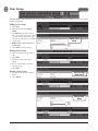
1
e3 eMerge User Programming Guide
1.
Introduction
This manual contains information regarding the programming and configuration of the eMerge access control system. The
system offers multi-station ability to secure doors, manage access of personnel, create and analyze reports, and monitor the
system remotely from any Web browser. All monitored activity at the facility is recorded in the system memory — providing
a record of all Card Holder entries and exits, input detection, and security or fire detection, if desired.
The system can be seamlessly scaled up, via software keys, to provide increased door and reader capacity, enhanced features,
and higher level capabilities.
General Features
The following is a feature summary of the Controller:
• Browser-based management enables system status and updates from any location, with any supported OS, using any
supported browser — Chrome ver. 22 or higher; IE 9.0 or higher; Firefox ver. 13 or higher; Safari ver. 5.1.7 or higher.
• Supports access from iPhone, iPad and Android devices.
• Intuitive Wizard allows for ultra-fast setup.
• Configure the system to perform automatic functions on specific days and times. For example, schedule when a door is
unlocked or when an employee can gain access to the facility.
• Create, view and print customized reports using the reporting tool.
• Create a set of instructions that the system will follow when an event occurs. For example, when a door is forced open
the system can be instructed to turn on a camera and display a graphic.
• Configure the system to store custom information about each Card Holder such as phone number or employee ID.
• Define up to 30 holidays for use as special schedules. For example, schedule a door to remain locked during a holiday.
• Configure the system to send email and text message notifications.
• Software updates for new feature and product enhancements.
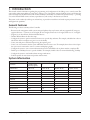
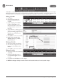
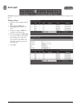
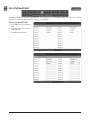
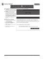
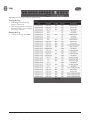
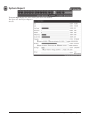
System Information
Feature
System Capacities
36*
64*
128*
Maximum readers
Inputs
Outputs
Card holders
Cards per person
Card formats
Access Levels
1 (scalable to 4 with
optional key upgrades)
8 (4 in / 4 out)
12
8
1,000
12
32
25
72 (36 in / 36 out)
108*
72*
5,000
32
32
125
128 (64 in / 64 out)
192*
128*
5,000
64
64
125
256 (128 in / 128 out)
384*
256*
15,000
32
32
256
Time Schedules
25
125
125
256
16
30,000
Yes*
16
30,000
Yes*
32
50,000
Yes*
Doors/Portals
Simultaneous system users
8
Online transactions
15,000
Elevator
N/A
* NOTE: Using optional expansion Controllers
e3 eMerge User Programming Guide
2
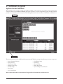
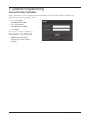
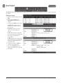
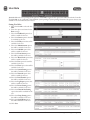
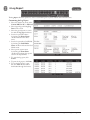
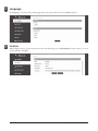
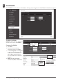
2. Software Layout
System Server Software
The Controller browser interface includes two methods available to the operator for programming and navigation. These
methods include using the Toolbar and Wizard. The Toolbar provides access to all configuration options; whereas the Wizard
provides access to the core system components. The following illustration shows the location of the Toolbar and Wizard icon.
Tool Bar
Wizard Icon
The first time the system is run, the Wizard will run automatically. This allows setting of the following core system components:
•
•
•
•
•
•
•
System Language Selection
System License
Card Format Setup
Holiday Group Setup
Schedule Setup
Door Setup
Access Level Setup
•
•
•
•
•
Card Holder Setup
Card Setup
Network Setup
Dealer Registration
System Startup Screen Selection
Refer to the Section in the rear of this manual “Using the Wizard” for details on each Wizard screen.
3
e3 eMerge User Programming Guide
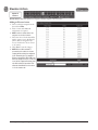
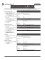
Toolbar Menu
The Toolbar provides access to all setup, programming, management, and reporting options of the Controller.
Dashboard: The default system software page, which is primarily used to monitor and acknowledge recent events.
Camera: Configure and view cameras and DVRs if installed.
Administration: Add, edit or delete Card Holders, card formats and Access Levels, badge layouts and templates.
Schedule: Add and edit time schedules, holidays and unlock schedules.
Events: Create events that are assigned to actions. For example, a time schedule can be assigned to an auxiliary output.
Threat Level: Enable and configure Threat Level settings, if Threat Levels are enabled.
Device Setting: Configure the doors, elevators, inputs and outputs that are licensed and available within the system.
Edit Controller locations and region.
User Setting: Set user fields, define the operators that can login and select their level of system access.
System Setting: Update, backup, restore or reset the Controller.
Network Setting: Configure the IP address, FTP, update server, SMTP, time server, and RMC.
Floor Setting: Load a floor plan graphic, which will be displayed on the Dashboard.
Data Transfer: Export or import data using a CSV file.
Log: Opens the log database allowing the user to generate, view, and print log reports.
Report: Provides system and event reporting, smart reports feature customizable report formats.
Group Table: Enter cards, door and camera groups as well as configure Access Level groups.
Site Management: View and edit client, site, and device information, option to add a custom logo.
Logout: Logs the operator out of the system.
e3 eMerge User Programming Guide
4
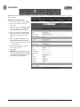
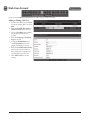
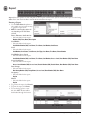
3. System Programming
Connect to the Controller
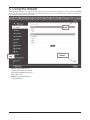
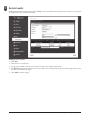
Open a web browser on a local computer and enter the IP address of the Controller (Default = 192.168.0.250).
The browser presents the login page as shown.
1. Enter the User ID.
• Default User ID = admin
2. Enter the Password.
• Default Password = admin
3. Click Login.
Just in case, a link is displayed to
send a message to the eMerge Super
Administrator for a forgotten password.
✓ NOTE: The Super Administrator
password is set in Device Settings >
Controller
5
e3 eMerge User Programming Guide
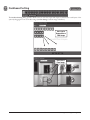
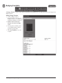
Dashboard
Click the Dashboard icon to open the Dashboard window, which displays incoming events and allows users to view,
acknowledge, and clear events. The Dashboard allows the operator to monitor real-time activities in the facility — for
example, use of a valid card or a door forced open. The Dashboard also provides the ability to manually lock and unlock doors
and activate outputs.
M-Unlock: Unlocks the door for the
time defined as the Door Unlock Time
(default = 3 seconds).
E-Unlock: Unlocks the door until the
user clicks Lock.
Lock: Locks the door
Trigger: Activates the selected auxiliary
or elevator output according to the Aux
Output settings (see Aux Output to
configure output settings).
e3 eMerge User Programming Guide
E-Unlock
Door
Selector
M-Unlock
6
Lock
Trigger
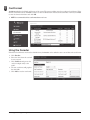
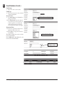
Dashboard Setting
The Dashboard Setting dialog provides default icons for each door, input and output. Customize the visual layout of the
system by dragging the icons to the floor image (see Floor Setting to add an image of the floor).
Icons can be
Dragged Over a
Floor Image
Icons Over a
Floor Image
7
e3 eMerge User Programming Guide
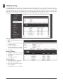
Camera View
Optional
Feature
Camera View allows the user to select defined IP camera video matrix and various camera views.
A license upgrade is required to use this feature.
Defining Camera Views
1. Click Edit and add the desired
cameras from the drop-down list.
This defines the camera position in
the camera view.
2. Select 1mode, 4mode, 9mode, or
16mode to set the amount of
cameras displayed in the view
window.
3. Click Save.
✓ NOTE: Live video is dependent on
IP camera settings and browser
capabilities. Not all camera and browser
configurations are supported.
e3 eMerge User Programming Guide
8
Camera Setting
Optional
Feature
Camera Setting allows configuration of IP cameras. A license upgrade is required to use this feature.
Adding a Camera
1. Click New and enter a name and
description for the camera.
2. Select a camera brand from the
drop-down list. If your camera is
not listed, select Other.
3. Enter the additional information
for the camera. This information is
provided in the camera’s installation
manual.
• Browser Address: The IP address of
the camera.
• Control Address: The IP address of
the camera.
• IP Port: The port to obtain video
from the camera.
• ID: User name of the admin or live
view user of the camera.
• Password: Password of the admin
or live view user of the camera.
• Door: The door on the system that
linked to the camera (for triggering
events).
• Enable PTZ: Enable if the camera
has PTZ capability.
4. Enter the camera’s Image URL,
and Motion JPEG URL,. This
information is typically listed in the
camera’s installation manual.
5. Click Add.
✓ NOTE: Live video is dependent on
IP camera settings and browser
capabilities. Not all camera and browser
configurations are supported.
9
e3 eMerge User Programming Guide
DVR View
Optional
Feature
DVR View allows the user to select defined IP DVR video matrix and different DVR views. A license upgrade is required to
use this feature. Refer to the DVR manual for programming information.
e3 eMerge User Programming Guide
10
DVR Setting
Optional
Feature
DVR Setting allows configuration of digital video recorders. A license upgrade is required to use this feature.
Adding a DVR
1. Click New and enter a name and
description for the DVR.
2. Select a DVR brand from the dropdown list. If your DVR is not listed,
select Other.
3. Enter the additional information
for the DVR. This information is
provided in the camera’s installation
manual.
4. Click Add.
✓ NOTE: Digital Watchdog DVR integration
is only compatible with Microsoft IE9
or higher, 32-bit version only. The DVR
setting must be configured using IE and
will require installation of an ActiveX
component. Refer to DVR manual for
additional information.
11
e3 eMerge User Programming Guide
Card Holder
Card Holders are individuals who access the facility and are entered in the system. Access credentials are assigned to Card
Holders
Creating a Card Holder
1. Click New.
2. Enter the name and contact
information of the Card Holder.
3. Under File Upload, click Snapshot
to take a picture from an attached
USB camera or click Browse to
select a file to assign an image to
the Card Holder for identification
purposes.
✓ NOTE: Picture files can be 20 Kb
maximum. JPG, BMP, or PNG formats.
Click New to
Enter a Card
Holder
Click to Use
Picture File
Card Holder Options
1. Select ADA Timing for extended
timing for the door relay.
2. Select Exempt to allow the Card
Holder to bypass Anti-Passback
rules (except occupancy rules) if the
Card Holder is allowed access to
the region.
3. Select a Web User Account to give
the Card Holder operator privileges
to the Controller.
4. Choose the highest Threat Level
that the Card Holder will be
allowed access.
✓ NOTE: A Card Holder cannot access a
door if either the Door Threat Level or
the System Threat Level is greater than
the Card Holder Threat Level.
5. Click Save.
Click
to Take
Picture
Card Holder Badge
Click to Print
Badge
1. Select the Template for the badge.
✓ NOTE: See Section Badge Printing for
details on setting up badge design
templates.
2. Click Print Badge to launch the
badge printing window.
3. Click Print Badge to select the
printer and print out the badge.
e3 eMerge User Programming Guide
12
Card Holder (Cont.)
Assigning a Card to an Existing Card Holder
1. Select the Card Holder from the
main window.
2. Click Add Card.
Click Add Card
Card Format
3. Select the appropriate Card Format
from the drop-down field.
Card Number
Choose the Card Format
4. Enter the Card Number, or use the
Auto Scan feature.
Auto Scan
5. Choose the Auto Scan door reader
where the card will be presented.
✓ NOTE: Card scanner can only be used
with doors 1 - 4.
6. Click Card Scan and present the
card to the reader. The new card
number will populate the data field.
Choose the Auto Scan Door
Card Status
7. Select the current Card Status.
Enter the Card Number
or Click Card Scan
Card Type
8. Select the function for the card with
Card Type dropdown.
Select the Card Status
Select the Card Type
13
e3 eMerge User Programming Guide
Card Holder (Cont.)
Access Level
9. For Select Type select Individual or
Group access level.
10. For Select Level select the desired
access levels (or use the search icon
to find a specific access level) and
click the right arrow to move the
access level to the field on the right.
Use Arrows to
Choose Levels
Activation Date
11. Choose an optional activation and
expiration date for the card.
12. Click Save to assign the card to the
Card Holder.
The added card will show on the card list
for the Card Holder.
Click Add Card to add additional cards
for the selected Card Holder.
e3 eMerge User Programming Guide
14
Card Format
Card Format displays the default card formats of the system. The system has several pre-configured card formats. If the
desired card format is not listed, a custom format may be added.
Adding a Card Format
1. Click New.
2. Enter a name and description
(optional) for the card format.
3. Enter the facility code bit/length,
card number bit/length and parity
information as provided by the card
manufacturer.
4. Click Add to save the changes.
✓ NOTE: It is recommended to delete card
formats that are not in use.
Using the Decoder
If the desired card format is not listed
as a default format, the Decoder can be
utilized to auto scan and detect the card
format.
1. Click Decoder.
2. Select the door where the card will
be auto scanned.
3. Click Card Scan and present the
card (or multiple cards) to the
reader.
4. The new card format will populate
the data fields.
5. Click Add to save the new format.
✓ NOTE: The decoder takes a “best guess”
based on existing card formats. Without
knowledge of the card’s start bits and
length, it cannot guarantee proper
decoding.
15
e3 eMerge User Programming Guide
Access Level
An Access Level establishes which doors the Card Holder can access and when they are allowed to access them. Access Levels
are comprised of a time schedule and door(s).
Adding an Access Level
1. Click New.
2. Enter the desired Access Level
Name and Description (optional).
3. Assign a time schedule to the
Access Level by choosing it from
the Schedule dropdown menu.
4. Select Group or Individual for the
Access Group Type.
5. For Door List, select the desired
doors (or use the search icon to find
a specific door) and click the right
arrow to move the doors to the field
on the right.
✓ Note: Ctrl-click or shift-click will select
multiple doors.
6. Click Add to save the changes.
Adding Access
Level
Editing an Access Level
1. Select an Access Level from the list
and click Edit.
2. Make the desired edits.
3. Click Save to save the changes.
Deleting an Access Level
1. Select an Access Level from the list
and click Edit.
2. Click Delete.
3. A confirmation window will pop
up, click OK to delete the Access
Level.
Editing Access
Level
e3 eMerge User Programming Guide
16
Badging Layout
The Badging Layout Module is used to design printable badges. The badge orientation, background, logo, Card Holder
picture, and text fields can be customized and saved under a layout name.
Layout
1. Use the Select Layout dropdown to
modify an existing badge layout, or
create a new layout.
Orientation
2. Choose Landscape (wide) or
Portrait (tall) for the badge
orientation.
Background File
3. If a background is needed, browse
for the Background File.
Logo
4. Set a logo size to fit the logo with
the Logo Width and Logo Height
settings.
5. Set the logo position on the badge.
The X Position is the number of
pixels in from the left edge. The
Y Position is the number of pixels
down from the top edge.
Picture
6. Set the Card Holder Picture (100 pixels wide by 130 pixels high) position on the badge. The X Position is the
number of pixels in from the left edge. The Y Position is the number of pixels down from the top edge.
Text Fields
7. Enter names for the text fields in the Field ID boxes.
8. Set each text field position with the X Position and Y Position settings.
9. Set the Max Number of Characters for each of the text fields. The field will be truncated to this length when it is
populated from the database.
Save and Preview
10. Click Preview to look at the badge layout then adjust any design settings.
11. When the badge layout is as desired, click Save to save the layout.
17
e3 eMerge User Programming Guide
Badging Template
A Badging Template is used to select which Card Holder data populates the text fields positioned on the badge by the
Badging Layout.
Editing a Badge Template
1. Choose a Badge Layout or
Badge Template to edit with the
dropdown selectors. A sample of the
badge layout displays for reference.
✓ Note: The number of fields listed
depends on the fields in the Badge
Layout
2. For each of the text fields, choose
a Card Holder database field to
populate the badge field.
3. Click Save Template to store the
template.
e3 eMerge User Programming Guide
18
Schedule
A Schedule is a combination of a time interval and one or more days of the week. Use schedules to identify the hours and days
when inputs, outputs or door access are in operation. Assign holiday groups to the schedule to control when operations occur
on holidays. There is one default time schedule of Always, which is defined as 00:00-23:59, seven days per week.
Adding a Schedule
1. Click New.
2. Enter the desired name and
description (optional) for the
schedule.
3. Adjust the sliders for the Start
Time and End Time on days
when the schedule is to be active.
(Collapse slider for no access on
that day.)
4. (Optional) Select a holiday group to
allow access on the holidays in the
group. If a holiday group is selected,
identify a start and end time for
holiday access.
5. Click Add to save the new schedule.
✓ Note: To create a schedule with a
“Midnight Crossing” (e.g., 16:00 to
00:30) click Reverse.
Click New
Move Sliders for
Start and End Time
Deleting a Schedule
1. Select the schedule to be deleted.
2. The schedule will appear. Scroll to
the bottom of the page and click
Delete.
3. Click OK to confirm the deletion.
Click Add
Editing a Schedule
1. Select the schedule to be edited and
click Edit.
2. Perform the desired changes to
the Name, Description and time
intervals.
3. Scroll down and click Save to save the changes.
✓ NOTE: When changing or deleting a schedule review the unlock schedules and Access Levels for possible changes.
19
e3 eMerge User Programming Guide
Holiday
Use Holiday to define days and times during the year when holiday hours are used. When the holiday starts, the Controller
switches from regular hours to holiday hours. When the holiday ends, the regular hours resume. You can assign four holiday
groups with up to 30 holidays total among the groups. A holiday can include any number of consecutive days within the same
calendar year. The system Controller has preconfigured holiday groups based upon the country you selected in the Language
section of the Wizard. The holiday groups are preconfigured through 2021 for quick setup.
Editing a Holiday
1. Select the desired holiday and click
Edit.
2. Change the start date and end date
to the desired date.
3. Rename the holiday (it is
recommended that pre-configured
holidays be renamed when edited).
4. Click Save.
Deleting a Holiday
To Add a Holiday
Click New
1. Highlight the holiday to be deleted.
2. Click Delete. A confirmation box
will appear.
3. Click OK to confirm.
Adding a Holiday
1. Click New and enter the desired
name, start date and end date.
2. Select the desired holiday group for
the new holiday.
3. Click Add to save the new holiday.
✓ NOTE: Access will be restricted on any
holiday assigned to a holiday group.
See Schedules for information on how
to allow access on holidays.
Select a Holiday
then Click Edit
Click Add
e3 eMerge User Programming Guide
20
Unlock Schedule
An Unlock Schedule defines which Schedule will be used with selected access devices to automatically unlock one or more
doors.
Adding an Unlock Schedule
1. Click New.
2. Enter a Unlock Schedule Name.
3. Select the Schedule when the door
will be unlocked.
4. Click the Select Type drop-down
to select an individual door or a
group of doors.
5. For Unlock Device, select the
desired doors (or use the search icon
to find a specific door) and click the
right arrow to move the doors to
the field on the right.
Click Add to create the unlock schedule.
To Add an Unlock
Schedule Click New
Click Save
Editing an Unlock Schedule
1. Select the desired Unlock Schedule
and click Edit.
2. Edit the Unlock Schedule Name,
Schedule Type, Unlock Device.
3. Click Save.
Deleting an Unlock Schedule
1. Select the Unlock Schedule to be
deleted.
2. Click Delete. A confirmation box
will appear.
3. Click OK to confirm.
Select Unlock Schedule
and Click Edit
21
e3 eMerge User Programming Guide
One Time Unlock Schedule
A One Time Unlock Schedule defines one date and time to automatically unlock one selected door.
Adding a One Time Unlock Schedule
1. Click New.
2. Enter a Name for the One Time
Unlock Schedule.
3. Select the Date when the door will
be unlocked.
4. Select the Start Time and End
Time for the unlock period.
5. Click the drop-down to select a
door to unlock.
Click Add to create the One Time
Unlock Schedule.
To Add a One Time Unlock
Schedule Click New
Editing a One Time Schedule
Click Save
1. Select the desired One Time
Unlock Schedule and click Edit.
2. Make the changes desired.
3. Click Save.
Deleting a One Time Schedule
1. Select the desired One Time
Unlock Schedule to be deleted.
2. Click Delete. A confirmation box
will appear.
3. Click OK to confirm.
Select One Time Unlock
Schedule and Click Edit
e3 eMerge User Programming Guide
22
Event Action
Event Action allows the operator to create events that are assigned to actions. For example, the operator may assign a time
schedule to an auxiliary output.
Adding an Event Action
1. Click New and enter a name and
description.
2. In the Basic section, name the
event, fill in a Description, and
select a Schedule for the time the
Event Action will be active.
To Add an Event
Action Click New
Event
3. In the Event section, click Insert to
add a new event.
4. Choose the type of equipment that
can trigger the event action in the
Event Source Type dropdown.
5. Under Where, choose the event
source location(s) by selecting the
location(s) and clicking the right
arrow to move it to the field on the
right.
6. Under Event, choose the event(s)
to monitor by selecting the event(s)
and clicking the right arrow to
move it to the field on the right.
This is the event(s) that will trigger
the action.
Choose Where &
What Event
Action Triggers
Aux Output
Action
7. In the Action section, click Insert.
8. Choose either Aux Output or
System for the Action Source Type.
Aux Output
• This is the auxiliary relay(s) that will
respond to the event. Select them
and move it to the right by clicking
the right arrow.
System
• These are various messages and
operations that the system can
perform if the Event Action
triggers.
✓ NOTE: To have the system send an
e-mail for an event, use the Where
dropdown and select Send E-Mail.
9. Click Action Save and Save in each
section to save the settings.
Action Triggers
System Event
Choose what the
Action will do
Enter Text for E-Mail and
Dashboard Messages
23
e3 eMerge User Programming Guide
Event Code
Event Code lists the events that are available to the operator. The user can configure the event to display in the Dashboard
and/or require the operator to acknowledge the event.
Selecting Event Codes
1. On the Event Code list, edit the
checkboxes for the events codes that
will display on the dashboard if they
occur.
2. On the Event Code list, edit
the checkboxes for the events
codes that will require operator
acknowledgment if they occur.
Use the Search button to find specific
event codes or event code names.
Check to
Display Event
Check to
Require Event
Acknowledgment
e3 eMerge User Programming Guide
24
Threat Level
Optional
Feature
Threat Levels are used in systems to modify existing unlock schedules and Access Level privileges. The system has five
pre-defined Threat Levels. The names of each can be changed to match installation requirements.
Current Threat Level Setting
1. Click Edit to change or disable the
Threat Level.
2. Un-check the Turn Off Threat
Level checkbox to enable Threat
Levels.
3. Use the Threat Level dropdown
menu to select a Threat Level.
4. Click Save.
✓ NOTE: When the Threat Level is Off,
defined Access Level privileges and
unlock schedules operate normally.
Click to
Change
Current Threat
Level Setting
25
Current Threat
Level
Threat Level
Disable
e3 eMerge User Programming Guide
Threat Level Setting
Optional
Feature
There is a three tier hierarchy of Threat Levels to consider when configuring an system. First the System Threat Level, second
the Door Threat Level and third the Card Holder Threat Level. See the Door and Card Holder sections for details on setting
the Door and Card Holder Threat Levels.
System Threat Level Setup
1. Click Edit to change the number or
title of the Threat Levels.
2. Select the number of Threat Levels
available for the system with the
Threat Level Count dropdown. Up
to 25 Threat Levels can be defined.
3. The titles of each Threat Level
can be customized to suit the
installation.
4. Click Save when finished.
Click to Edit
Threat Levels
Number of
Threat Levels
Threat Levels
Titles
e3 eMerge User Programming Guide
26
Door
Door displays the doors that are assigned to the system. Click on the door name for additional information pertaining to
each door.
✓ NOTE: When programming various
elements of the system, do not use the
same name for multiple items (e.g., use
Door 1, Door 2, etc.).
✓ NOTE: Do not use special characters
(<>?{})(*&%#@^{ \|/).
Editing a Door
Select the desired door. Scroll to the
bottom of the page and click Edit.
After making any edits, be sure to click
Save at the bottom of the page.
Basic
1. Enter the desired Name and
Description (optional) for the door.
2. For multi-floor installations, select
the Floor.
Reader
1. In the Reader section, select the
settings for the door’s reader.
Door Contact
1. In the Door Contact section, check
the Enable checkbox if a door
contact is used.
2. Name the door contact and select
its type.
3. Adjust the Held Open Time,
which is the length of time the door
can be open following a valid access
request.
4. The ADA Open Time is an
additional time added to the Held
Open Time.
Rex
1. Enter the Door Rex Name for the
door’s request to exit switch.
2. Select the type of Rex switch.
3. Check the Rex Activates Door
Lock checkbox to have the Rex
activate the door’s lock.
27
e3 eMerge User Programming Guide
Door (Cont.)
Door Lock Mode
1. Choose a Door Lock Name to
name the lock for logging.
2. Configure Door Lock Mode as
Normal
follows:
Door Lock Mode
• Normal: Lock activates in response
to a valid access request and REX
unlocks door for exit.
• Locked: Does NOT grant access in
response to REX, card or code.
• Locked w/REX: Remains in locked
Man-Trap
mode, ONLY REX will activate
Door
Lock Mode
lock.
• Unlocked: Door will remain
unlocked at ALL times.
• Man-Trap: Sets the door lock for
use in conjunction with another
door to create a man-trap passage.
A Man-Trap will only allow one
door to be opened if the other door
is locked. When Man-Trap is selected, Man-Trap Mode options appear:
• Unlock: No security on Entry or Exit.
• Secure Entry/Free Egress: Two options, both options use card access to enter the Exterior Door. Option 1 allows
free exit through the exterior door; Option 2 requires card access to exit through the exterior door.
• Restricted Entry and Exit: Four options, all options use card access to enter the Exterior Door. Option 1 allows
free exit through the exterior door; Option 2 requires card access to exit through the interior door, Option 3
requires card access to exit through the exterior door. Option 4 requires card access to exit through either door.
• Pair Door: Select the second Man-Trap door that is closest to the secured area.
3. Select the Door’s Default Status. This setting will be determined by the lock type (energized or de-energized).
4. Assign Re-Lock on Open if desired. This will re-lock the door immediately upon opening the door.
5. Adjust Door Unlock Time if desired. This is the length of time the door relay is active after a valid access request.
e3 eMerge User Programming Guide
28
Door (Cont.)
Door Status Alarm Output
Sets the actions of a door contact on the door. The door contact must be enabled to use these functions.
1. Check Forced Door to trigger the
door alarm output if the door opens,
but no access was granted.
2. Check Held Door to trigger the
door alarm output if the door is
held open longer than the Held
Open Time.
3. Select Energized or De-energized
for the Default State of the Door
Status Alarm Output.
4. Select an Output to use for the
Door Status Alarm Output.
5. Click to enable an Alarm Shunt
output to operate when access is
granted to the secured door.
6. Select Energized or De-energized
for the Default State of the Alarm
Shunt Output.
7. Select an Output to use for the
Alarm Shunt Output.
Threat Level
1. Select the highest Threat Level
allowed before the door will
automatically lock.
✓ Note: An unlocked door will lock if the
System Threat Level is greater than the
Door Threat Level; including doors that
are unlocked by schedule.
✓ Note: The Dashboard M-Unlock and
E-Unlock may be used to unlock a door
that has been locked due to elevated
system Threat Level.
2. Check Ignore REX to ignore input
from a Rex button if the current
System Threat Level is higher than
the Door Threat Level.
Anti-Passback
1. Check to enable Timed Anti
Passback. Select a time in seconds
to disable a credential after it has
been used to grant access.
2. Check to enable Room Anti
Passback. Select a time in seconds
to disable access to a room after
access has been granted to the room.
29
e3 eMerge User Programming Guide
Door (Cont.)
First Man In Rule
First Man in Rule unlocks a door when first Card Holder enters.
1. Check Enable to use a First Man
In Rule.
2. Select a Grace Period to allow the
selected first man Card Holder(s)
access minutes before a scheduled
start time.
3. Select up to three time Schedules
for the rule to be active.
4. Select the Type of Card Holders
(individual or group).
5. Search or choose Card Holder(s) or
Groups for the rule. Use the arrows
to move the name(s) in and out.
Manager In Rule
With Manager in Rule enabled, if a Card Holder designated as a Door Manager has not entered the system within a specific
time period, the door will not unlock.
1. Check Enable to use the Manager
In Rule.
2. Select up to three time Schedules
for the rule to be active.
3. Select the Type of Card Holders
(individual or group).
4. Search or choose Card Holder(s) or
Groups for the rule. Use the arrows
to move the name(s) in and out.
Two Man Rule
With Two Man Rule enabled, two Card Holders must present credentials at the same time in order to unlock the door.
Credentials must be presented in the proper sequence (Card Holder 1 then Card Holder 2), or access will be denied.
1. Check Enable to use the Two Man
Rule.
2. Enter a Time in seconds allowed
for the second Card Holder to
present their credentials.
3. Search or choose Card Holder 1 for
the rule. Use the arrows to move the
name(s) in and out.
4. Search or choose Card Holder 2 for
the rule. Use the arrows to move the
name(s) in and out.
Saving Changes
After making any edits, be sure to click Save at the bottom of the page.
e3 eMerge User Programming Guide
30
Elevator
Optional
Feature
Elevator displays the elevators that are assigned to the system. Click on the elevator name to view or edit the settings of the
elevator. Each elevator cab requires an elevator module, which activates up to 8 outputs for controlling access to floors. Access
to more than 8 floors requires additional elevator modules.
Editing an Elevator
1. Click the desired elevator from the
list and click Edit.
2. For Elevator Name, enter a name
for the elevator.
3. For Description, enter a description
for the elevator.
4. Select Elevator Client for the
factory default setting for the client,
or Elevator Client Extension
to add more floors to an existing
elevator client.
5. Select the Reader Type that
matches the elevator reader from
the dropdown list.
6. Select the Elevator Lock Mode
from the dropdown list.
7. Select the Threat Level from the
dropdown list.
8. Select the Floor from the
dropdown list.
9. Click Save.
31
e3 eMerge User Programming Guide
Aux Input
Aux Input displays the inputs that are assigned to the system. Click on the input name to view or edit the settings of the
input.
Editing an Input
1. Select the desired input and click
Edit.
2. Enter a desired Name and
Description (optional) for the
input.
3. Assign the input to a Floor for
viewing on the Dashboard.
4. Select the appropriate Input Type
for the input. This setting will be
determined by the wiring and
type of switch connected to the
input (NC or NO, supervised or
unsupervised).
5. Click Save.
e3 eMerge User Programming Guide
32
Aux Output
Aux Output displays the outputs that are assigned to the system. Click on the output name to view or edit the settings of
the output.
Editing an Output
1. Select the desired output and click
Edit.
2. Enter a desired Name and
Description (optional) for the
output.
3. Configure the Mode of the output:
• Single Pulse: Output latches in
response to a valid event for the
time entered.
• Repeating: Output opens and
closes in a cycle for the time
entered.
• E-On: Will latch the output ON
when activated from the dashboard.
Press Stop on dashboard turn
output OFF.
• E-Off: Will latch the output OFF
when activated from the dashboard.
Press Stop on dashboard to turn
output back ON.
4. Assign the output to a Floor for
viewing on the Dashboard.
5. Select the Default State of the
output (energized or de-energized).
6. Click Save.
Single Pulse
Aux Output
Repeating
Aux Output
33
e3 eMerge User Programming Guide
Elevator Action
Optional
Feature
Elevator Action allows the operator to assign the elevator outputs to Access Levels.
Adding an Elevator Action
1. Select an elevator output from the
list and click Edit.
2. Enter a name and additional
information as required.
✓ NOTE: In order to activate floors, first
assign an access level to doors.
3. Select the Access Level that will be
used to grant access to the floor(s).
(Doors must be assigned to the
Access Level for the Access Level
to be active).
4. Click Save to save the changes.
✓ NOTE: When a valid credential is
presented to the reader, the elevator
outputs will be activated as configured
in the Elevator Action. For example, if
Elevator outputs EO 1, EO 2, EO 3 and
EO 4 are assigned to Floors 1-4 Access
Level, all four outputs will activate when
the valid credential is presented. This
allows the Card Holder to select floors
1-4 in the elevator cab.
e3 eMerge User Programming Guide
34
Controller
Controller displays information pertaining to each system Controller. Click on the Controller name on the list to view or
edit information.
Editing the Controller Info
1. Select the Controller and click Edit.
2. Enter a desired name and location
(optional).
3. Select the appropriate Tamper Input
value. This will be determined by the
wiring configuration of the input.
4. Select the appropriate Power Fault
Input value. This will be determined
by the wiring configuration of the
input.
5. Enter the ID and Password of the
Super Administration Account. This
is the top-level administration account
for the Controller.
6. Set the default language, page and
floor for the account.
7. Click Save.
✓ IMPORTANT! It is highly advised to change
the Super Administrator password. Keep it
in a safe place. This password cannot be
recovered if it is lost or forgotten.
35
e3 eMerge User Programming Guide
Region
A Region is an area (a “zone”) you want to limit security into and/or out of. Entering or exiting a Region occurs through
controlled door access. The In Reader and Out Reader (if used) for a door can each be assigned a Region.
The primary usage for Regions is to count or control occupancy and implement door access sequence rules to prevent or track
access to areas if the correct door access sequence is not met.
A Region can contain up to five nested partitions called “Sub Regions” and “Child Regions”, each controlling access to a
sub-section of the “Parent” Region.
Region Rules Overview
• Regions contain Credentials that are
owned by Card Holders. Because
Card Holders can have multiple
Credentials, a Card Holder could exist
in multiple Regions at the same time
but a Credential can only exist in one
Region at a time.
• Once the Card Holder enters a
Region, they remain in the Region
for occupancy until they enter
another Region or exit the Region by
presenting a Credential on the out
reader.
• A Region can contain Sub Regions
and Child Regions that are contained
inside the main Region.
• Anti Passback and Tailgating rules are
applied to Regions.
• A maximum of 125 Regions are
supported on a system.
Examples of Regions
Regions should be programmed to suit
the controlled access requirements and the
expected Card Holder locations as they
move about the installation.
• Example 1: A company has a room
with its building that is used to store
hazardous chemicals. That room can
become a Hazardous Region within
the Building Region and restrict access
to a limited number of Card Holders.
• Example 2: A company has four
buildings at its facility. By making
each a Region and using occupancy, an
administrator can locate what building
a Card Holder is in if there is an
emergency.
e3 eMerge User Programming Guide
36
Region (cont.)
Child Regions
A Child Region follows the definition of a Region with these exceptions:
• A Child Region cannot have an
occupancy limit, only a Parent or Sub
Region can have an occupancy limit.
• The Card Holder does appear in the
Child Region on the Occupancy
Report. See Occupancy for more
information.
• Normally, a Child Region will be fully
contained within the Parent Region
but the rules do not restrict this
• A Child Region is logically contained inside of it Parent Region. This means if the Card Holder in the Child Region,
they are, for occupancy, in the Parent Region.
• Anti PassBack and TailGating rules can be applied to Child Regions
• There is a maximum of 20 Child Regions per Region.
• There is a maximum of 250 total Child Regions per system.
Child Region Notes
• Under the Region setting for the Door - A Child of a Parent would be a Class 2. A Child of a Child would be Class
3. etc. When a Class other than Class 1 is selected, the Parent Region option will turn into a drop down list.
• Specify the Parent Region for this Child Region from the drop down list
Sub Regions
Sub Regions function the same as Child Regions, except for occupancy counting. Sub Regions can report occupancy counts
of the Sub Region as well as contribute to the occupancy count of the Parent Region.
37
e3 eMerge User Programming Guide
Region (cont.)
Adding or Editing a Region
1. Click New to add a region or click Edit to modify a region.
Basic
2. For the Region’s Name, enter up to 30
characters.
3. In the Description field, enter a short
description of the Region.
4. Select the Depth for the Region. Class
1 is the highest. Class 2 through Class
5 are Sub Regions or Child Regions,
each sub Class must physically reside
inside the next lower number Class
number around it.
5. If Parent Region is left empty (the
default) the Region becomes the
Parent Region. If the Region is Class
2-5, select Sub Region or Child
Region’s the Parent Region.
6. If the Region is used only for Muster
Station personnel assembly, check
Only Muster. The remaining Region
options are not used or available when
Only Muster is selected.
Muster Region Notes
• A Muster Region is a Region used as a centralized place to do a roll call.
• A Muster Region will remove Card Holders from their currently occupied Region and place them in the Muster
Region where the reader is at.
• Maximum number of Muster Regions 125.
• A Muster Region is attached to an In/Out set of readers for a door (both readers must be defined to the Region).
• A Muster Region is valid for the entire site. It is possible to have multiple Muster Regions but they all serve in
parallel for the entire site. For instance, each building of a site could have its own Muster Reader but a Card Holder
could go to any of the Muster stations to check in.
• A Muster Region cannot contain another Muster Region.
e3 eMerge User Programming Guide
38
Region (cont.)
Passback Violations
Anti PassBack is intended to prevent Card Holders from sharing credentials to gain access. With timed anti passback, a
Passback Violation event occurs when the same credential is used to request access to the same door or region more than once
during a set period of time.
1. Select the level for the Default
Violation.
• None: Timed Anti Passback is not
in use (default setting).
• Soft: Triggers an alarm then grants
access if the Anti Passback time
interval has not expired before the
credential was used at the same
reader again.
• Hard: Triggers an alarm and
prevents access if the Anti Passback
time interval has not expired before
the credential was used at the same
reader again.
2. Enter the number of minutes (0-999) for Anti Passback Interval. This is the length of time that presenting the same
credential again will cause an anti passback violation. Check the Enable Grace checkbox to allow the administrator to
permit grace for the Card Holder in case of an anti passback violation.
✓ NOTE: Selecting 0 minutes for the Anti Passback Interval allows no time and effectively disables the Passback Violation for the
region. Don’t set it to 0 and expect Anti Passback to function properly.
3. To minimize clutter on the Grace Screen, check the Reset Violations Daily checkbox to clear all Passback Violations
for the Region once a day.
4. When Reset Violations Daily is enabled, select the Time of Day for the reset to occur.
Passback Violation Operation Notes
•
•
•
•
Presenting a credential again before the timer has expired will restart the timer.
Timed Anti Passback is for In Readers only, it has no effect on Out Readers.
If the Card Holder exits the Region through an Out Reader, the timer is reset and stopped.
When Enable Grace is set, Card Holders can only re-enter the Region by properly exiting the Region first or by being
Graced in.
• The log message for a Passback Violation is “Denied Region Anti Passback Violation”.
• Anti Passback can also be set for a door not assigned to a Region using the Door setup menu, but if the door is later
assigned to a Region, the Region Anti Passback setting will override the door setting.
39
e3 eMerge User Programming Guide
Region (cont.)
Tailgate Violations
A Tailgate Violation occurs when an authorized Card Holder is granted access and one or more persons pass through the
open controlled access point in addition to the authorized Card Holder. Tailgating is detected when a Card Holder tries to
exit a Region, or enter another Region, from a Region which they were never granted access to enter.
1. Select the level for the Default
Violation.
• None: Tailgating feature is turned
off (default setting).
• Soft: Triggers an alarm then grants
access.
• Hard: Triggers an alarm and
prevents access through the Out
Reader and/or the In Reader of a
sub Region.
Tailgate Violation Operation Notes
• In the Door setup menu, the Out Reader Region must be set to the Region with the Tailgate Default Violation
turned ON.
• Hard Tailgating is only for the most secure facilities and requires In Readers and Out Readers at all doors.
• With Hard Tailgating, if a Card Holder leaves a Region by any other means than authorized controlled exiting, a
Tailgate Violation will occur at any other door until either (1) the Card Holder presents their credential to a Muster
Reader (this removes the Tailgate Violation and adds the Card Holder to the Muster Region), or (2) the Card Holder
is Graced by the system administrator using the Grace Tab on the Dashboard (they will be placed in the Region
where they swiped their card to enter), or (3) the Card Holder can somehow get back into the Region the system
thinks they Occupy and then exit that Region correctly.
• Hard Tailgating applies to the Region the system thinks the Card Holder is in and will deny access to any other
non-connected Region. For example, suppose there are two separate buildings, Bldg1 is Region 1 with Hard
Tailgating, Bldg2 is Region 2 with Soft Tailgating. If the Card Holder enters Bldg 1 and occupies Region 1, then
leaves Bldg 1 without being granted exit access, the Card Holder will be denied access to any other door (trying to reenter Bldg1, entering or exiting Bldg 2). However, if the Card Holder enters Bldg 2 first and Occupies Region 2, then
leaves Bldg 2 without being granted exit access, the Card Holder will create a warning but will be allowed access into
either building.
e3 eMerge User Programming Guide
40
Region (cont.)
Occupancy Limit Enforcement
Occupancy Limit Enforcement counts and/or limits (restricts) the number of Card Holder credentials that can occupy a given
Region at the same time.
The log message for an Occupancy Limit violation is “Access Denied Occupancy Limit Violation”.
1. Select the level for the Default
Violation.
• None: The Controller counts
occupancy, but no action results
(default setting).
• Soft: When a Card Holder presents credentials to enter the Region and the occupancy limit has been reached, an
alarm activates and the Card Holder is granted access. An alarm will continue to activate for each new Card Holder
that presents credentials until the occupancy count falls under the Maximum Occupancy number.
• Hard: When a Card Holder presents credentials to enter the Region and the occupancy limit has been reached, an
alarm activates and the Card Holder is denied access.
2. Enter the Maximum Occupancy number (0-99999) allowed in the Region. (Entering 0 results in no occupancy limit,
the Controller just counts occupancy.)
Occupancy Rules
• When a Card Holder presents a credential to a reader and is granted access, the Card Holder credential enters into
the Region specified by the In Reader and exits the Card Holder credential from all other Regions.
• A Card Holder credential can only exist in one Region at a time.
• A Card Holder may occupy multiple regions if they are assigned multiple credentials.
• A Child Region cannot have an Occupancy Limit because its occupancy count is included as part of its Parent
Region.
Region Occupancy Counting
• The occupancy count for a Region is the sum of the occupancy count for the Region plus any Child Regions or Sub
Regions, which in turn may have Children or Sub Regions of their own.
• When a Card Holder credential enters a Region, the occupancy count for that Region increases by 1.
• When a Card Holder credential exits a Region, the occupancy count for that Region decreases by 1.
• The Occupancy count can never go below 0.
Occupancy Limit Enforcement Notes
• For occupancy counting to work effectively, both In Readers and Out Readers must be used.
• An Out Reader cannot be in an uncontrolled space (no Region assigned) unless the In Reader is also in an
uncontrolled space (means it is not connected to a Region).
• The In Reader and Out Reader cannot be the same device unless they are both setup as in an uncontrolled space or a
Muster Region.
• Card Holders with the Exempt option enabled still obey the occupancy limit enforcement rules.
• A denied access attempt at an occupied Region does not restrict the Card Holder from entering other Regions with
normal access.
41
e3 eMerge User Programming Guide
Region (cont.)
Deadman Region
A Dead Man region requires each Card Holder, after entering the region to periodically check in for safety reasons.
Card Holders are issued a normal card to enter and exit the region and a special “Dead Man Card” to indicate activity
An alarm will activate after the Card Holder’s DeadMan Interval has expired unless they have:
✓ Swiped their Dead Man Card at
one of the Dead Man Regions Out
Readers. This will reset the timer to
the DeadMan Interval for that Card
Holder.
✓ Exited the Region using their normal
card. This will cancel the timer for that
Card Holder.
✓ Swiped their normal card at a Muster station. This will cancel the timer for that Card Holder.
Once the alarm has been activated, the alarm may be deactivated by:
✓ Card Holder swiping their Dead Man Card at one of the Dead Man Regions Out Readers. This will reset the timer
to DeadMan Interval for that Card Holder. It may or may not turn off the alarm.
✓ Card Holder exiting using their normal card. This will cancel the timer for that Card Holder. It may or may not turn
off the alarm.
✓ Card Holder swiping their normal card at a Muster station. This will cancel the timer for that Card Holder. It may or
may not turn off the alarm.
✓ System Administrator Acknowledges the alarm. This will deactivate the alarm even if all Card Holder alarm triggers
have not been cleared.
If multiple Card Holder have triggered the Dead Man Alarm, then only when the last Card Holder has been cleared will
the alarm be deactivated.
Creating a Dead Man Region
1. Check the DeadMan Region checkbox to create a Dead Man Region.
2. Enter a time in minutes (5-60) for the DeadMan Interval. The default is 5 minutes.
Dead Man Region Notes
• In the Door setting for the reader in the Dead Man Region, the Out Reader Region must be set to the Region
defined as a Dead Man region.
e3 eMerge User Programming Guide
42
Region (cont.)
A HazMat Region can be locked down to prevent entry and exit in case of hazardous materials emergency. When the
selected AUX input is triggered, all doors associated with the HazMat Region will be locked and all access in and out of
the HazMat Region will be denied until the selected AUX input has returned to normal. After a HazMat alarm has been
triggered, a HazMat Unlock Card is required to cancel the alarm.
Creating a HazMat Region
1. Check the HazMat Region checkbox
to create a HazMat Region.
2. For the HazMat Input, select the
Auxiliary Input (1-4) that the trigger
device is connected to.
HazMat Region Notes
• The log message for a hazardous materials alarm is: “Hazmat Region Lockdown [Region Name]”.
• For a HazMat Unlock Card, in the Card setting for a Card Holder select HazMat Unlock for the Card Type.
43
e3 eMerge User Programming Guide
User Defined Field
User Defined Fields are 20 custom data fields that can be assigned to a Card Holder profile. This field can be used for
employee ID or other specific information unique to a Card Holder.
Editing User Defined Fields
1. Click Edit to enter user defined
fields.
2. Enter any custom data in the 20
User Info fields.
3. Click Save when finished.
e3 eMerge User Programming Guide
44
User Role
User Roles define the access privilege of the operators. A User ID is assigned to each person who will work with the Controller.
Each User ID can be configured to have different system privileges. System privileges determine the options the user has
available in the Controller browser interface.
Setting User Roles
1. Select the User ID to edit and click
Edit.
2. Enter the options and name for the
Basic settings.
3. Select the Dashboard options that
will be available for the user.
4. Select the Camera options that will
be available for the user.
5. Select the DVR options that will be
available for the user.
6. Select the Administration options
that will be available for the user.
7. Select the Schedule options that
will be available for the user.
8. Select the Event Action options
that will be available for the user.
9. Select the Threat Level options that
will be available for the user.
10. Select the User options that will be
available for the user.
11. Select the Floor options that will be
available for the user.
12. Select the System Setting options
that will be available for the user.
13. Select the Network options that
will be available for the user.
14. Select the Data Transfer options
that will be available for the user.
15. Select the Log Report options that
will be available for the user.
16. Select the Device Setting options
that will be available for the user.
17. Select the Client & Site Setting
options that will be available for the
user.
18. Select the Group Setting options
that will be available for the user.
19. Select the Quick Menu options
that will be available for the user.
20. Click Save.
45
e3 eMerge User Programming Guide
Web User Account
Create or edit the Web User Accounts that are used to log into to the Controller.
Adding or Editing a Web User
1. To add a new Web User, click New.
To edit an existing Web User, click
Edit.
2. Enter the User ID, Password and
Web User Name of the new user.
3. Assign a User Role, which defines
the privilege level of the user
account.
4. Enter the Language and Default
Page for the user.
5. Assign the Default Floor and
enable Floor Show if the floor
graphic will display to the user.
6. Enter the Auto Disconnect Time,
which is the amount of time, in
hours, before the Controller will
automatically log out the user.
7. Click Add or Save to save the
settings.
e3 eMerge User Programming Guide
46
Update
Update allows the user to update the firmware of the Controller.
Updating the Firmware
1. Select the location of the firmware
file. User PC, SD Card, or Update
Server.
2. Click Update.
✓ NOTE: This function only updates the
firmware of the Controller. To update
the client firmware refer to Client
Management.
◆ WARNING: Servers and Clients MUST be
using the same firmware version!
✓ NOTE: Gateway and DNS IP addresses
must be configured to access the
update server. Refer to IP Address to
configure these settings.
47
e3 eMerge User Programming Guide
Backup
Backup enables the system backup and defines the backup device, time and location of the backup.
The system automatically assigns a name
to the backup at the time of the backup
with the following format:
•
•
•
•
•
•
•
YYYYMMDDHHMMSS
YYYY = 4-digit year
MM = 2-digit month
DD = 2-digit day
HH = 2-digit hour
MM = 2-digit minutes
SS = 2-digit seconds
Scheduled Backup
1. To change the backup settings, click
Edit.
2. Set a log name for the backup in
the Name field.
3. For automatically scheduled daily
backup check the Enable checkbox.
4. Select SD Card or FTP for the
backup device.
5. Choose a time for the daily backup
with the Backup Time selector.
6. Click Save.
Immediate Backup
1. Select User PC, SD Card or FTP
Server for the backup device.
2. To run an immediate backup, click
Backup.
e3 eMerge User Programming Guide
48
Restore
Restore allows the operator to restore the system from a backup.
Restoring the System
1. Select the location of the restore
file. User PC, SD Card, or FTP
Server.
2. Enter a file name and path or click
Browse to choose the file to restore
from.
3. Click Restore.
49
e3 eMerge User Programming Guide
Save & Reboot
Save and Reboot can save the Controller data only, or save the Controller data and reboot the Controller.
Saving Data
1. Click Save Data to force a data save
on the Controller.
2. Enter a super administrator
password and click OK.
Saving Data and Rebooting
1. Click Save Data & Reboot to force
a data save on the Controller and
restart the system.
2. Enter an super administrator
password and click OK.
e3 eMerge User Programming Guide
50
Factory Default
Factory Default will erase ALL Card Holder data, logs, IP settings and license key.
◆ !! IMPORTANT !!: Write down the license
key prior to performing a factory default.
◆ WARNING: It will take 3-5 minutes to
factory default a system. DO NOT
power down when performing a factory
default. Make sure the electrical power
source is reliable when performing a
factory default. Any loss of power during
a factory default can damage your
system.
Resetting to Factory Defaults
1. After heeding the above warnings,
click Factory Default.
2. Enter an Super Administrator
Password and click OK.
3. Wait 3-5 minutes for the system to
reset and reboot.
4. Enter the license key when the
system restarts.
51
e3 eMerge User Programming Guide
IP Address
The Internet Protocol (IP) Address area sets all of the network settings including the IP Address, Subnet Mask, Gateway
Address, DNS Server 1, DNS Server 2, and HTTP Port.
DHCP assigns an IP address to the Controller automatically on a network containing a DHCP Server (a router will typically
have a built-in DHCP Server). When Static is selected, options IP Address, Subnet Mask, Gateway must be entered.
DNS is an Internet service that translates domain names into IP addresses. The IP address of a DNS is required if using NTP
time server or SMTP e-mail.
Editing Network Settings
1. Select DHCP or Static. (Skip to
Step 5 if using DHCP).
2. Enter a static IP Address for the
Controller to use on the LAN.
The first three values must match
other devices on the network (e.g.,
192.1.0.x).
3. Enter the Subnet Mask address.
The Subnet Mask determines
the manual address mask used
by the Controller (typically
255.255.255.0).
4. Set the Gateway Address to match
the address of the router that
connects the LAN to the Internet.
5. Enter the IP address of the DNS Server 1 (optional, use for NTP time server access or SMTP e-mail connection).
6. Enter the IP address of the DNS Server 2 (optional, use for NTP time server access or SMTP e-mail connection).
7. Enter the HTTP Port number for remote Web browser connection (typically 80).
8. Check the HTTPS checkbox if RMC is being used.
9. If using HTTPS, edit the HTTPS Port number if required (default is 443).
10. When finished entering the network settings, click Save & Reboot.
Upload cer-key
For installations using HyperText Transport Protocol Secure (HTTPS) communications, the eMerge system uses a default
security key and certificate. If the installations network requires a different specific security key and certificate, edit the two
items.
1. Click Upload cer-key.
2. Enter the Private Key into the SSL
Toolbox.
3. Enter the Certificate into the SSL
Toolbox.
4. Click Save & Reboot.
e3 eMerge User Programming Guide
52
FTP
File Transfer Protocol (FTP) enables and configures the system to backup to an FTP location. Enter FTP information as
provided by your web host.
Editing FTP Settings
1. Check the Enable checkbox to
enable an FTP server connection.
2. Enter the IP address of the FTP
server in the Server Address field.
3. Enter the communications port
number into the Server Port field.
4. Enter the FTP server user name
into the Server ID field.
5. Enter the FTP server password into
the Server Password field.
6. Check the Server Passive Mode
checkbox if required by the FTP
server.
7. Enter the upload directory path
used on the FTP server in the
Upload DIR field.
8. Click Save to save the changes.
53
e3 eMerge User Programming Guide
SMTP
Simple Mail Transfer Protocol (SMTP) provides the ability to send email to specified email addresses.
Editing SMTP Settings
1. To allow the Controller to send
SMTP e-mail messages, check the
Use SMTP Service checkbox.
2. Enter the SMTP mail server URL
(typically “mail.your email domain.
com”) the the SMTP Server field.
3. Enter the incoming port number of
the SMTP mail server in the Port
field.
4. Enable TLS if your mail server uses
secure server communication (this
is common). Check the TLS Used
checkbox to enable TLS.
5. Enter your SMTP mail server user
ID (your email address) in the ID
field.
6. Enter your SMTP mail server
Password in the Password field.
7. Test the system by entering an
email address in the Send to
(E-mail Address) field and click
Test.
8. Click Save to save the changes.
✓ NOTE: The Controller’s Gateway IP
address and DNS address must be
properly configured to be able to send
email. Refer to IP Address to configure
these settings.
e3 eMerge User Programming Guide
54
Time Server
Time Server provides the ability to sync the system to a time server or manually set the time.
✓ NOTE: Gateway IP and DNS IP
addresses must be configured to
access public time servers. Refer to IP
Address to configure these settings.
Editing Time Server Settings
1. To manually set the system time
select Manual Time Setting. Skip
to Step 6.
2. To use a time server, select NTP
Server Synchronization.
3. Select one of the time servers from
the Server Address drop box.
4. Select the time period for the time
server synchronization from the
Sync Time dropdown. Skip to Step
7.
5. Select the time zone at the
Controller’s installation location
from the Sync Time Zone
dropdown.
6. For manual date and time setting,
enter the current date and time in
the Date and Time fields.
7. To enable Daylight Saving Time
(DST) select ON. Enter the DST
start and end dates in the two fields.
8. Click Save.
55
e3 eMerge User Programming Guide
RMC
The Remote Management Console (RMC) server is used to manage multiple Controllers, usually from a remote location.
If using RMC, the settings for the RMC
server’s URL, Domain UUID, and
Device ID will need to be edited in the
Controller.
Editing RMC Settings
1. Click the Connect to RMC
checkbox if an RMC server will be
used.
2. Enter the RMC Server URL.
3. Enter the RMC Domain UUID.
4. Enter the Device ID.
5. Click Save to keep the changes.
Refer to the RMC User Guide P/N
620-100701 for details on RMC setup
and operation
e3 eMerge User Programming Guide
56
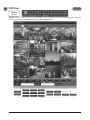
Floor Setting
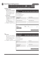
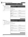
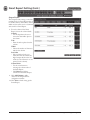
Floor Setting allows the operator to load and view floor plan graphics which will be displayed on the Dashboard.
Adding a Graphic
1. To add a new floor plan graphic,
click New.
2. Enter a name for the floor in the
Floor Name field.
3. Enter a description for the floor
graphic in the Description field.
4. To add a new image, click Choose
File and select the graphics file.
✓ NOTE: The maximum JPG, BMP, or PNG
image size is 685 pixels wide by 340
pixels high and the maximum file size
is 150KB
5. To save the graphic, click Add.
Editing Floor
Setting
Viewing a Graphic
1. Click on a floor graphic in the table.
2. The floor graphic will be previewed
on the screen.
Deleting a Graphic
1. Click on a floor graphic in the table.
2. Click Delete to remove the entire
floor graphic record, or click Edit
then Delete Image File to just
delete the graphic and leave the
floor name and description.
Adding Floor
Setting
57
e3 eMerge User Programming Guide
User Data Export
User Data Export provides the ability to export Card Holder data to a comma separated value (CSV) file.
Exporting User Data
1. To export the Card Holder data,
click Export.
2. The CSV file of the Card Holder
data will be downloaded through
the browser.
e3 eMerge User Programming Guide
58
User Data Import
User Data Import provides the ability to import Card Holder data from a comma separated value (CSV) file.
To successfully import a file, the column
headers must match those present in the
User Data Export file. It is suggested
to perform a data export and use it as a
template for the import file.
You must have the related card formats
and Access Levels configured before
importing the file.
◆ WARNING: Do not use special characters <>?{})(*&%#@ in any fields.
✓ NOTE: Data will not be imported unless the information is entered in the same manner in which it appears in the system software
database (e.g., case sensitive and syntax sensitive).
Importing User Data
1. To skip Card Holder records that currently exist in the system, select Skip. To overwrite Card Holder records that
currently exist in the system, select Overwrite.
2. Click Choose File and select the file to import.
3. Click Import.
59
e3 eMerge User Programming Guide
Log
Log displays the most recent events for quick viewing.
Viewing the Log
1. When Log is selected, the log
displays on the screen.
2. Click the page number or arrows at
the bottom of the screen to display
other pages of the log.
Printing the Log
3. To print out the log, click Print.
e3 eMerge User Programming Guide
60
4. Log Report
The Log Report allows the operator to create a customized report of system, network and Controller events.
Customizing the Log Report
1. Select the database to search, either
Current DB, User PC, or SD Card.
2. Select beginning and ending Log
Date for the search.
3. Select the general events to search
for with the Log Type checkboxes.
4. Search for a particular device
by checking the Device Name
checkbox and enter the device
name.
5. Search for a particular Card Holder
by checking the Card Holder
Name checkbox and enter the Card
Holder name.
6. Select specific system events
by checking the Event Name
checkbox and selecting the specific
event in the dropdown list.
7. To create the log report, click
Search.
8. To print the log report, click Print.
9. To save the log report as a text
file, click CSV. The data will be
downloaded through the browser.
61
e3 eMerge User Programming Guide
Log Management
Log Management allows the operator to create a backup of all log events. The backup can be scheduled and directed to the
SD card on the Controller or an FTP location. The backup can also be manually generated to a CSV or DB file.
Automatic Log Backup
1. Enter the percentage of log fullness
to trigger a pop up message or
automatic log backup.
2. The message displayed can be edited
in the Pop Up Message field.
3. Enter a name for the backup in the
Name field.
4. To enable the automatic log backup
check the Enable checkbox.
5. Select either SD Card or FTP for
the Backup Device.
6. Click Save.
Schedule Log Backup
1. Enter a name for the backup in the
Name field.
2. To enable the scheduled log backup
check the Enable checkbox.
3. Select either SD Card or FTP for
the Backup Device.
4. Select the daily time for the
scheduled log backup from the
Backup Time dropdown.
Log Reset
1. To delete all log data in memory,
click Reset
2. Enter an administrator password to
confirm the log reset.
3. Click OK.
Manual Log Backup
1. Select the backup type, either CSV
or Database format.
2. Click Backup.
e3 eMerge User Programming Guide
62
Report
Report allows the operator to view and print or save a report of items in the system’s memory. The report is created using
Filters. Items that match the filters entered will be included in the report.
Running a Report
1. Use the Table Name dropdown to
select which area of system memory
to generate a report from.
✓ NOTE: The remaining filter options will
vary depending on the Table Name
selected.
Doors, Elevators, Aux In & Out
• Select the filters for the report.
Number (NO), Floor, Name, Description
Card Holder
• Select the filters for the report.
Card Holder Number (NO), Last Name, First Name, Card Number, Card Status
Card
• Select the filters for the report.
Card Number, Card Status, Card Format, Card Type, Last Name, First Name, Phone Number
Card Holder Access Levels
• Select the filters for the report.
Card Holder Number (NO), Last Name, First Name, Card Number, Access Level, Door Number (NO), Door Name
Access Level Doors
• Select the filters for the report.
Access Level Number (NO), Access Level, Reader Number (NO), Reader Name, Door Number (NO), Door Name
Door Groups
• Select the filters for the report.
Door Group Number (NO), Group Name, Access Level, Door Number (NO), Door Name
Occupancy
• Select the filter for the report.
Region
Muster
• Select the filter for the report.
Region
2. To generate the report, click Search.
3. To print the report, click Print.
4. To save the log report as a text
file, click CSV. The data will be
downloaded through the browser.
63
e3 eMerge User Programming Guide
Access Report
The Access Report allows the user to generate reports for all access events that occur at any door or elevator.
Running an Access Report
1. Select Door or Elevator for the
Type to search for.
2. Select the starting and ending date
range for the search in the Date
fields.
3. Select the Door, Card Holder, and
Access Level to search for in the
Condition fields.
4. To generate the report, click Search.
5. To print the report, click Print.
6. To export the report as a file, click
CSV. The data will be downloaded
through the browser.
e3 eMerge User Programming Guide
64
System Report
The System Report displays the current memory allocation of the database.
The report runs when System Report is
selected.
65
e3 eMerge User Programming Guide
Smart Report
The Smart Report option displays Smart Reports that were generated with the Smart Report Setting.
Options are available for viewing,
printing, and exporting the Smart Report.
Viewing a Smart Report
1. With the selector buttons for the
desired Smart Report, click View.
2. A Smart Report Viewer browser
window will open displaying the
Smart Report.
3. Use the page numbers at the
bottom to navigate to other pages of
the Smart Report.
Printing a Smart Report
1. With the selector buttons for the
desired Smart Report, click Print.
2. A Smart Report Viewer browser
window will open displaying the
Smart Report.
3. Click the Print button in the upper
right corner to send the Smart
Report to the system’s printer.
Exporting to a Text File
1. With the selector buttons for the
desired Smart Report, click Text.
2. The browser will prompt for saving
or viewing. Select your choice.
3. A basic text file will be created.
Exporting to a CSV File
1. With the selector buttons for the
desired Smart Report, click CSV.
2. The browser will prompt for saving
or viewing. Select your choice.
3. A comma separated value file for
use in spreadsheets will be created.
Exporting to a HTML File
1. With the selector buttons for the desired Smart Report, click HTML.
2. The browser will prompt for saving or viewing. Select your choice.
3. An HTML file for viewing in a browser will be created.
e3 eMerge User Programming Guide
66
Smart Report Setting
Smart Report Setting is a function that allows creating and saving custom designed system reports with interactive features.
Each element of the report can be customized to suit the installation or management of the installation.
Creating a Smart Report
1. Click Create New Report to begin
setting up a smart report template.
Date / Time
Report Covers Time Frame
• Select one of the time frame
options, enter any variable data,
then click Add New Time
Frame to add the filter to the
Smart Report.
Limit Daily Time To
• Select one of the daily time limit
options, enter any variable data,
choose to include or exclude
these times, then click Add New
Time Frame to add the filter to
the Smart Report.
Include Holidays
• Choose holidays to include in
the report with the dropdown
selector.
Exclude Holidays
• Choose holidays to exclude in
the report with the dropdown
selector.
2. Click Next to setup the Card
Holder filter.
67
e3 eMerge User Programming Guide
Smart Report Setting (Cont.)
Cardholders
Cardholder Filters
• Select one of the Card Holder
filter options for no restriction,
ask when report is run, or use
manual Card Holder selection
with Card Holders or Card
Holder groups.
Attribute Filter
• Select a Card Holder Attribute,
then choose a logical Relation
and Value for the filter. Check
the Ask checkbox for a prompt
at run time.
• Click Add Attribute to add the
filter to the Smart Report.
3. Click Next to setup the Card filter.
Cards
Card Filters
• Select one of the Card Holder
filter options for no restriction,
ask when report is run, or use
manual Card Holder selection
with cards or card types.
4. Click Next to setup the Doors filter.
e3 eMerge User Programming Guide
68
Smart Report Setting (Cont.)
Doors
Door Filters
• Select one of the door filter
options for no restriction, ask
when report is run, or use manual
door selection, Threat Level
selection, or doors on selected
floors.
5. Click Next to setup the Elevators
filters.
Elevators
Elevator Filters
• Select one of the elevator filter
options for all elevators, ask
when report is run, or use manual
elevator selection, elevator relays,
or elevators on selected floors.
6. Click Next to setup the Events
filters.
69
e3 eMerge User Programming Guide
Smart Report Setting (Cont.)
Events
Event Filters
• Select one of the event filter
options for all events, ask when
report is run, or use the event
filter checkboxes.
Event Groups
• Use the checkboxes to select
Event Group filters for the Smart
Report.
Individual Events
• Use the checkboxes to select
Individual Event filters for the
Smart Report.
7. Click Next to setup the Output
Format for the Smart Report.
e3 eMerge User Programming Guide
70
Smart Report Setting (Cont.)
Output Format
The Output Format settings control the
resulting look of a Smart Report when it
is run. The columns, column titles, column
widths and sort orders can be customized
and saved for a Smart Report.
8. For each column of the Smart
Report, choose the column details.
Column
• Use the dropdown selectors to
choose the data field to place in
the column.
Title
• Enter the title to place above the
column.
Width
• Choose the number of characters
wide for the column.
Sort Order
• Select a number for the sort
order, the lower the number, the
higher output will be in the sort
results (or select None for no sort
priority for the column).
Column Order
• Use the arrow buttons to
rearrange the column order of
the Smart Report.
• Click Remove to delete a
column from the Smart Report.
9. Click Add Column to add a
column to the Output Format
configuration window.
10. Click Next to finish setting up the
Smart Report.
71
e3 eMerge User Programming Guide
Smart Report Setting (Cont.)
Save Report
Saving the report saves all the filter and
column options from the other Smart
Report Setting tabs.
Save Report
• Enter a Report Name for the
customized Smart Report.
• Enter the maximum number of
lines to limit the report length.
• Enter the number of lines
allowed for each page of the
report. A form feed will occur
when this line count is reached.
Allow Access To
• Choose which User Roles will be
allowed to run the Smart Report.
11. Select Save Only to save the
customized Smart Report without
running the report. Select Save and
Run to save the customized Smart
Report and run the report.
e3 eMerge User Programming Guide
72
Card Holder Group
A Card Holder Group contains individual Card Holders for the purposes of common access and reporting.
Adding a Card Holder Group
1. Click New.
2. Enter the Card Holder Group
Name.
3. For Card Holder List, select the
desired card holders (or use the
search icon to find a specific card
holder) and click the right arrow to
move them to the field on the right.
✓ NOTE: Ctrl-click or shift-click will select
multiple Card Holders.
4. Click Add to save the changes.
Adding a Card
Holder Group
Editing a Card Holder Group
1. Click on the Card Holder Group
name to edit.
2. Click Edit.
3. The Card Holder Group name can
be edited.
4. Card holders can be added or
removed from the group.
5. Click Save.
Deleting a Card Holder Group
1. Click on the Card Holder Group
name to delete.
2. Click Delete.
Selecting a Card
Holder Group to Edit
Editing a Card
Holder Group
73
e3 eMerge User Programming Guide
Door Group
The Door Group allows individual doors to be combined in groups. The group can then be added to an Access Level for
simpler management.
Adding a Door Group
1. Click New.
2. Enter the desired door Group
Name.
3. For Door List, select the desired
doors (or use the search icon to find
a specific door) and click the right
arrow to move the doors to the field
on the right.
✓ NOTE: Ctrl-click or shift-click will select
multiple doors.
4. Click Add to save the changes.
Adding a Door
Group
Editing a Door Group
1. Click on the Door Group name to
edit.
2. Click Edit.
3. The Door Group name can be
edited.
4. Doors can be added or removed
from the group.
5. Click Save.
Deleting a Door Group
Selecting a Door
Group to Edit
1. Click on the Door Group name to
delete.
2. Click Delete.
Editing a Door
Group
e3 eMerge User Programming Guide
74
Camera Group
The Camera Group allows individual cameras to be combined in groups.
Adding a Camera Group
1. Click New.
2. Enter the desired camera Group
Name.
3. For Camera List, select the desired
cameras (or use the search icon to
find a specific camera) and click the
right arrow to move the cameras to
the field on the right.
✓ NOTE: Ctrl-click or shift-click will select
multiple cameras.
4. Click Add to save the changes.
Adding a Camera
Group
Editing a Camera Group
1. Click on the Camera Group name
to edit.
2. Click Edit.
3. The Camera Group name can be
edited.
4. Cameras can be added or removed
from the group.
5. Click Save.
Deleting a Camera Group
1. Click on the Camera Group name
to delete.
2. Click Delete.
Selecting a Camera
Group to Edit
Editing a Camera
Group
75
e3 eMerge User Programming Guide
Access Level Group
Add individual Access Levels to Access Level Groups. These groups can then be assigned to cards in the Card Holder section.
Adding an Access Level Group
1. Click New.
2. Enter the desired Group Name.
3. For Access Level List, select the
desired access level (or use the
search icon to find a access level)
and click the right arrow to move
the access levels to the field on the
right.
✓ NOTE: Ctrl-click or shift-click will select
multiple Access Levels.
4. Click Add to save the changes.
Adding an Access
Level Group
Editing a Access Level Group
1. Click on the Access Level Group
name to edit.
2. Click Edit.
3. The Access Level Group name can
be edited.
4. Access Levels can be added or
removed from the group.
5. Click Save.
Deleting a Access Level Group
1. Click on the Access Level Group
name to delete.
2. Click Delete.
Selecting an Access
Level Group to Edit
Editing an Access
Level Group
e3 eMerge User Programming Guide
76
Client Management
Optional
Feature
Client Management allows the user to enable/disable, connect/disconnect, and update client Controllers associated to the
main Controller’s server database.
Client Management allows user to update the firmware of the clients. The firmware for an individual Controller may be
updated by clicking the Update Client button for the Controller. If multiple Controllers are connected to a main Controller,
the Update All will update all the clients.
✓ NOTE: It will take 2-5 minutes to update
each client. During that time the clients
will be off-line.
✓ NOTE: Gateway and DNS IP addresses
must be configured to access the
Update Server. Refer to IP Address to
configure these settings.
✓ WARNING: All Controllers in a system
MUST be using the same firmware
version.
Client Management
Buttons
Managing Clients
1. The installed client(s) will be listed
in the Client Management section.
2. Use the Client Management buttons to manage the system clients.
Global Commands
Update All
• Updates all connected Clients
Data Sync
• Re-sends Server Database to all Clients
Client Specific Commands
Client Disconnect
• Disables a client in the Server Database
Client Connect
• Enables a client in the Server Database
Delete Client
• Permanently removes Client from Server Database
Update Client
• Updates the selected Client firmware to the latest version
Client Reboot
• Reboots selected Client
77
e3 eMerge User Programming Guide
Client Replacement
Optional
Feature
Client Replacement is used when an existing client Controller is replaced with a new client Controller.
Replace a Client
1. Power off bad Client board and
disconnect from network. At the
Dashboard the Door and Aux icons
are grayed out.
2. Install replacement Client board on
the network and set the IP to the
same address as the bad client.
3. Save the MAC address of the new
client.
✓ NOTE: Leave the Server address set to
0.0.0.0
4. On the Controller, go to Site
Management > Client Replacement.
Select the IP/MAC of the bad
client and click Edit button.
5. Change the MAC address to the
replacement client
6. Login to the replacement client and
set the server IP and click Save.
7. After the replacement client
connects, the dashboard icons will
change from gray to color.
e3 eMerge User Programming Guide
78
Logout
Logout prevents unauthorized persons from working in the system but still allows all access control operations to continue.
To secure the system, be sure to logout when finished.
Logging Out of the Controller
1. When ready to exit, click Logout.
2. The Controller will logout the user
and return to the Login screen.
79
e3 eMerge User Programming Guide
4.
Using the Wizard
The Wizard allows the user to configure the basic settings of the system. Advance through each setting by clicking the Next
button. The Wizard will launch automatically the first time the system is run. Visit the Wizard at any time by clicking the
icon in the lower left corner of the window.
Exit the
Wizard
Click Next to
Advance
Wizard
Icon
✓ NOTE: When programming various
elements of the system, do not use the
same name for multiple items (e.g., use
Door 1, Door 2, etc.).
✓ NOTE: Do not use special characters
(<>?{})(*&%#@^{ \|/).
e3 eMerge User Programming Guide
80
Language
Use Language to select the country and language where the system will be located. Click Next to advance.
License
License displays the basic system information of the Controller. Please print the License Key for future needs or in case of
a factory default. Click Next.
81
e3 eMerge User Programming Guide
Card Format
Card Format displays the default card formats of the system. The system includes several pre-configured card formats. If the
desired card format is listed, click Next to advance to the next Wizard item. If the desired card format is not listed, click New
to enter the format information and click Add.
✓ NOTE: It is recommended to delete card formats that are not in use.
Using the Decoder
If the desired card format is not listed as a default format, the Decoder can be utilized to auto scan and detect the card format.
1. Click Decoder.
2. Select the door where the card will
be auto scanned.
3. Click Card Scan and present the
card (or multiple cards) to the
reader.
4. The new card format will populate
the data fields.
5. Click Add to save the new format.
e3 eMerge User Programming Guide
82
Holiday Group
Use Holiday Groups to define days and times during the year when holiday hours are used. When the holiday starts, the
Controller switches from regular hours to holiday hours. When the holiday ends, the regular hours resume. You can assign
four holiday groups with up to 30 holidays total among the groups. A holiday can include any number of consecutive days
within the same calendar year. The Controller has pre-configured holiday groups based upon the country you selected in the
Language section of the Wizard. The holiday groups are pre-configured through 2021 for quick set-up.
Editing a Holiday
1. Select the desired holiday and click
Edit.
2. Change the start date and end date
to the desired date.
3. Rename the holiday (it is
recommended that pre-configured
holidays be renamed when edited).
4. Click Save.
Deleting a Holiday
1. Highlight the holiday to be deleted.
2. Click Delete. A confirmation box
will appear.
3. Click OK to confirm.
Adding a Holiday
1. Click New and enter the desired
name, start date and end date.
2. Select the desired holiday group for
the new holiday.
3. Click Add to save the new holiday.
83
e3 eMerge User Programming Guide
Schedules
A Schedule is a combination of a time interval and one or more days of the week. Use schedules to identify the hours and days
when inputs, outputs or door access are in operation. Assign holiday groups to the schedule to control when operations occur
on holidays. There is one default time schedule of Always, which is defined as 00:00-23:59, seven days per week.
Adding a Schedule
1. Click New.
2. Enter the desired name and
description (optional) for the
schedule.
3. Adjust the sliders for the Start
Time and End Time on days
when the schedule is to be active.
(Collapse slider for no access on
that day.)
4. (Optional) Select a holiday group to
allow access on the holidays in the
group. If a holiday group is selected,
identify a start and end time for
holiday access.
5. Click Add to save the new schedule.
✓ Note: To create a schedule with a
“Midnight Crossing” (e.g., 16:00 to
00:30) click Reverse.
Move Sliders for
Start and End Time
Deleting a Schedule
1. Select the schedule to be deleted.
2. The schedule will appear. Scroll to
the bottom of the page and click
Delete.
3. Click OK to confirm the deletion.
Editing a Schedule
1. Select the schedule to be edited and
click Edit.
2. Perform the desired changes to
the name, description and time
intervals.
3. Scroll down and click Save to save
the changes.
e3 eMerge User Programming Guide
84
Doors
Displays the Doors that are assigned to the system. Click on the door name to view or edit each door.
Editing a Door
Select the desired door. Scroll to the
bottom of the page and click Edit.
After making any edits, be sure to click
Save at the bottom of the page.
Basic
1. Enter the desired Name and
Description (optional) for the door.
2. For multi-floor installations, select
the Floor.
Reader
1. In the Reader section, select the
settings for the door’s reader.
Door Contact
1. In the Door Contact section, check
the Enable checkbox if a door
contact is used.
2. Name the door contact and select
its type.
3. Adjust the Held Open Time,
which is the length of time the door
can be open following a valid access
request.
4. The ADA Open Time is an
additional time added to the Held
Open Time.
Rex
1. Enter the Door Rex Name for the door’s request to exit switch.
2. Select the type of Rex switch.
3. Check the Rex Activates Door Lock checkbox to have the Rex activate the door’s lock.
85
e3 eMerge User Programming Guide
Doors (Cont.)
Door Lock Mode
1. Choose a Door Lock Name to
name the lock for logging.
2. Configure Door Lock Mode as
Normal
follows:
Door Lock Mode
• Normal: Lock activates in response
to a valid access request and REX
unlocks door for exit.
• Locked: Does NOT grant access in
response to REX, card or code.
• Locked w/REX: Remains in locked
Man-Trap
mode, ONLY REX will activate
Door Lock Mode
lock.
• Unlocked: Door will remain
unlocked at ALL times.
• Man-Trap: Sets the door lock for
use in conjunction with another
door to create a man-trap passage.
A Man-Trap will only allow one
door to be opened if the other
door is locked. When Man-Trap is
selected, Man-Trap Mode options
appear:
• Unlock: No security on Entry or Exit.
• Secure Entry/Free Egress: Two options, both options use card access to enter the Exterior Door. Option 1 allows
free exit through the exterior door; Option 2 requires card access to exit through the exterior door.
• Restricted Entry and Exit: Four options, all options use card access to enter the Exterior Door. Option 1 allows
free exit through the exterior door; Option 2 requires card access to exit through the interior door, Option 3
requires card access to exit through the exterior door. Option 4 requires card access to exit through either door.
• Pair Door: Select the second Man-Trap door that is closest to the secured area.
3. Select the Door’s Default Status. This setting will be determined by the lock type (energized or de-energized).
4. Assign Re-Lock on Open if desired. This will re-lock the door immediately upon opening the door.
5. Adjust Door Unlock Time if desired. This is the length of time the door relay is active after a valid access request.
e3 eMerge User Programming Guide
86
Doors (Cont.)
Door Status Alarm Output
Sets the actions of a door contact on the door. The door contact must be enabled to use these functions.
1. Check Forced Door to trigger the
door alarm output if the door opens,
but no access was granted.
2. Check Held Door to trigger the
door alarm output if the door is
held open longer than the Held
Open Time.
3. Select Energized or De-energized
for the Default State of the Door
Status Alarm Output.
4. Select an Output to use for the
Door Status Alarm Output.
5. Click to enable an Alarm Shunt
output to operate when access is
granted to the secured door.
6. Select Energized or De-energized
for the Default State of the Alarm
Shunt Output.
7. Select an Output to use for the
Alarm Shunt Output.
Threat Level
1. Select the highest Threat Level
allowed before the door will
automatically lock.
✓ Note: An unlocked door will lock if the
System Threat Level is greater than the
Door Threat Level; including doors that
are unlocked by schedule.
✓ Note: The Dashboard M-Unlock and
E-Unlock may be used to unlock a door
that has been locked due to elevated
system Threat Level.
2. Check Ignore REX to ignore input
from a Rex button if the current
System Threat Level is higher than
the Door Threat Level.
Anti-Passback
1. Check to enable Timed Anti
Passback. Select a time in seconds
to disable a credential after it has
been used to grant access.
2. Check to enable Room Anti
Passback. Select a time in seconds
to disable access to a room after
access has been granted to the
room.
87
e3 eMerge User Programming Guide
Doors (Cont.)
First Man In Rule
First Man in Rule unlocks a door when first Card Holder enters.
1. Check Enable to use a First Man
In Rule.
2. Select a Grace Period to allow the
selected first man Card Holder(s)
access minutes before a scheduled
start time.
3. Select up to three time Schedules
for the rule to be active.
4. Select the Type of Card Holders
(individual or group).
5. Search or choose Card Holder(s) or
Groups for the rule. Use the arrows
to move the name(s) in and out.
Manager In Rule
With Manager in Rule enabled, if a Card Holder designated as a Door Manager has not entered the system within a specific
time period, the door will not unlock.
1. Check Enable to use the Manager
In Rule.
2. Select up to three time Schedules
for the rule to be active.
3. Select the Type of Card Holders
(individual or group).
4. Search or choose Card Holder(s) or
Groups for the rule. Use the arrows
to move the name(s) in and out.
Two Man Rule
With Two Man Rule enabled, two Card Holders must present credentials at the same time in order to unlock the door.
Credentials must be presented in the proper sequence (Card Holder 1 then Card Holder 2), or access will be denied.
1. Check Enable to use the Two Man
Rule.
2. Enter a Time in seconds allowed
for the second Card Holder to
present their credentials.
3. Search or choose Card Holder 1 for
the rule. Use the arrows to move the
name(s) in and out.
4. Search or choose Card Holder 2 for
the rule. Use the arrows to move the
name(s) in and out.
Saving Changes
After making any edits, be sure to click Save at the bottom of the page.
e3 eMerge User Programming Guide
88
Access Levels
An Access Level establishes which doors the Card Holder can access and when they are allowed to access them. Access Levels
are comprised of a time schedule and door(s).
Adding an Access Level
1.
2.
3.
4.
Click New.
Enter the Access Level name.
Assign a time schedule to the Access Level by choosing it from the drop-down menu.
For Door List select the desired doors (or use the search icon to find a specific door) and click the right arrow to move
the doors to the field on the right.
5. Click Add to save the changes.
89
e3 eMerge User Programming Guide
Card Holder
Use Card Holder to enter card users in the database. An image may be assigned to the Card Holder for identification purposes.
To Add a Card Holder
Individuals who enter the facility are
entered in the system as Card Holders.
Creating a Card Holder
1. Click New.
2. Enter the name and contact
information of the Card Holder.
3. Under File Upload, click Snapshot
to take a picture from an attached
USB camera or click Browse to
select a file to assign an image to
the Card Holder for identification
purposes.
✓ NOTE: Picture files can be 20 Kb
maximum. JPG, BMP, or PNG formats.
Click New to
enter a Card
Holder
Click to Use
Picture File
Click
to Take
Picture
e3 eMerge User Programming Guide
90
Card Holder (Cont.)
Card Holder Options
1. Select ADA Timing for extended
timing for the door relay.
2. Select Exempt to allow the Card
Holder to bypass Anti-Passback
rules (except occupancy rules) if the
Card Holder is allowed access to
the region.
3. Select a Web User Account to give
the Card Holder operator privileges
to the server software.
4. Choose the highest Threat Level
that the Card Holder will be
allowed access.
✓ NOTE: A Card Holder cannot access a
door if either the Door Threat Level or
the System Threat Level is greater than
the Card Holder Threat Level.
5. Click Save.
Card Holder Badge
1. Select the Template for the badge.
✓ NOTE: See Section Badge Printing for
details on setting up badge design
templates.
2. Click Print Badge to launch the
badge printing window.
3. Click Print Badge to select the
printer and print out the badge.
Click to Print
Badge
Assigning a Card to an Existing
Card Holder
Click Add Card
1. Select the Card Holder from the
main window.
2. Click Add Card.
Card Format
Choose the card format
3. Select the appropriate card format
from the drop-down field.
Card Number
4. Enter the Card Number, or use the
Auto Scan feature.
Auto Scan
5. Choose the Auto Scan door reader
where the card will be presented.
✓ NOTE: Card scanner can only be used
with doors 1 - 4.
6. Click Card Scan and present the
card to the reader. The new card
number will populate the data field.
Choose the auto scan door
Enter the card number
or click Card Scan
91
e3 eMerge User Programming Guide
Card Holder (Cont.)
Card Status
7. Select the card’s current status.
Card Type
8. Select the function for the card with
card type dropdown.
Access Level
Select the card status
9. For Select Type select Individual or
Group access level.
10. For Select Level select the desired
access levels (or use the search icon
to find a specific access level) and
click the right arrow to move the
access level to the field on the right.
Activation Date
11. Choose an optional activation and
expiration date for the card.
12. Click Save to assign the card to the
Card Holder.
The added card will show on the card list
for the Card Holder.
Select the Card Type
Click Add Card to add additional cards
for the selected Card Holder.
Use Arrows to
Choose Levels
e3 eMerge User Programming Guide
92
Card
Use Card to enter card numbers in the database and assign the card to a Card Holder.
Assigning a Card to a Card Holder
1. Select the Card Holder from the
main window.
2. Click Add Card.
3. If using Card Scan, select the door
where the card will be scanned.
4. Select the appropriate Card Format
from the drop-down.
5. Enter the Card Number of the
card.
6. If using Card Scan, click the button
and present the card to the reader.
The card number will populate the
Card Number field.
7. For Select Type select Individual or
Group access level.
8. For Select Level select the desired
access levels (or use the search icon
to find a specific access level) and
click the right arrow to move the
access level to the field on the right.
9. For Activation Date, choose an
optional activation and expiration
date for the card.
10. Click Save to assign the card to the
Card Holder.
Use Arrows to
Choose Levels
93
e3 eMerge User Programming Guide
Network
Enter the Network configuration information as provided by the IT administrator.
DHCP assigns an IP address to the Controller automatically on a network containing a DHCP Server (a router will typically
have a built-in DHCP Server). When Static is selected, options IP Address, Subnet Mask, Gateway must be entered.
DNS is an Internet service that translates domain names into IP addresses. The IP address of a DNS is required if using NTP
time server or SMTP e-mail.
Editing Network Settings
1. Select DHCP or Static. (Skip to Step 5 if using DHCP).
2. Enter a static IP Address for the Controller to use on the LAN. The first three values must match other devices on
the network (e.g., 192.1.0.x).
3. Enter the Subnet Mask address. The Subnet Mask determines the manual address mask used by the Controller
(typically 255.255.255.0).
4. Set the Gateway Address to match the address of the router that connects the LAN to the Internet.
5. Enter the IP address of the DNS Server 1 (optional, use for NTP time server access or SMTP e-mail connection).
6. Enter the IP address of the DNS Server 2 (optional, use for NTP time server access or SMTP e-mail connection).
7. Enter the HTTP Port number for remote Web browser connection (typically 80).
8. Check the HTTPS checkbox if RMC is being used.
9. If using HTTPS, edit the port number if required (default is 443).
10. When finished entering the network settings, click Save & Reboot.
Upload cer-key
For installations using HyperText Transport Protocol Secure (HTTPS) communications, the eMerge system uses a default
security key and certificate. If the installations network requires a different specific security key and certificate, edit the two
items.
1.
2.
3.
4.
Click Upload cer-key.
Enter the Private Key into the SSL Toolbox.
Enter the Certificate into the SSL Toolbox.
Click Save & Reboot.
e3 eMerge User Programming Guide
94
Dealer Registration
Dealer Registration is highly recommended for maximum system support. Please fill out the required information.
✓ NOTE: Gateway and DNS IP addresses
and SMTP must be configured to
send the registration email. Refer to IP
Address and SMTP to confirm these
settings.
Registering the System
1. Enter the Installing Dealer
information (required for upgrade
requests).
2. Enter the Site Information. This
is optional, but recommended to
document the site information in
the system.
3. When finished editing, click one of
the action buttons.
• The Register button will attempt to
send an email with the information
provided.
• The Save button will save the
contact information without
sending an email.
• The Clear button will clear the data
in the form.
95
e3 eMerge User Programming Guide
Start Save
Start Save is the command to save the initial settings for the system and select which page appears on logon.
Editing Startup Page
• Default Page: Use the dropdown selector to choose the page that the system will display upon logon.
• Save to SD Card: Leave this box selected to save the startup information to the SD card. Un-check to save the startup
information to the Controller’s memory.
e3 eMerge User Programming Guide
96
5.
Site Map
The Site Map is an overview of the pages within the Controller interface. Each page listed in the site map is linked to the
page it represents. This allows the user to quickly jump to any section listed in the site map.
Site Map Button
97
e3 eMerge User Programming Guide
6.
Lost Card
Lost Card is a utility to quickly identify the Card Holder associated with a lost card. The operator may enter any card number
to view the Card Holder that is associated with the card, reset a One Time Card, or override a Violation Grace.
Lost Card Button
e3 eMerge User Programming Guide
98
7.
License
License displays the basic system information of the Controller. Please print the License Key for future needs or in case of
a factory default.
✓ NOTE: You can use the MAC address to recover the license key for the system. Visit http://www.e3upgrade.com and enter the MAC
address and follow the directions.
Press + to View System Info
License Button
System Information
• Press the + sign to display the
system configuration information
and upgrade options.
• Current system information is
shown on the left.
• Upgrade options are shown on the
right. Select options from the two
dropdown boxes.
• Enter any comments to send with
the request in the text box.
• Click Request Upgrade to send in
an upgrade request.
Enter comments here
99
e3 eMerge User Programming Guide
8. End User License Agreement
IMPORTANT: THIS SOFTWARE END USER LICENSE AGREEMENT (“EULA”) IS A LEGAL AGREEMENT
BETWEEN YOU (EITHER AN INDIVIDUAL OR, IF PURCHASED OR OTHERWISE ACQUIRED BY OR
FOR AN ENTITY, AN ENTITY) AND NORTEK SECURITY & CONTROL LLC. READ IT CAREFULLY
BEFORE USING THE SOFTWARE. IT PROVIDES A LICENSE TO USE THE SOFTWARE AND CONTAINS
WARRANTY INFORMATION AND LIABILITY DISCLAIMERS. BY USING THE SOFTWARE, YOU ARE
CONFIRMING YOUR ACCEPTANCE OF THE SOFTWARE AND AGREEING TO BECOME BOUND BY THE
TERMS OF THIS AGREEMENT. IF YOU DO NOT AGREE TO BE BOUND BY THESE TERMS, THEN. DO NOT
USE THE SOFTWARE.
1.
Restrictions. This warranty does not apply to any Nortek Security & Control Products that: (a) have been altered,
except by Nortek Security & Control or with the written permission of Nortek Security & Control, (b) have not
been installed, operated, repaired, or maintained in accordance with instructions supplied by Nortek Security
& Control, (c) have been subjected to abnormal physical or electrical stress, misuse, negligence, or accident,
(d) are licensed, for beta, evaluation, testing or demonstration purposes; or (e) are systems for which Nortek
Security & Control has not received a payment of purchase price or license fee.
6.
1. “Nortek Security & Control” means Nortek Security & Control LLC.
2. “Product” means only the Nortek Security & Control eMerge and other Nortek Security & Control products.
3. “Software” means only the Nortek Security & Control software program(s) and third party software programs,
in each case, provided by Nortek Security & Control in connection with the Products, and may include
corresponding documentation, associated media, printed materials, and online or electronic documentation,
and all updates or upgrades of the above that are provided to you.
2.
License Grants
1. You may use the Software on an eMerge product; provided, however, that, notwithstanding anything contrary
contained herein, you may not use the Software on any non-Nortek Security & Control product or device,
including, but not limited to, mobile devices, internet appliances, set top boxes (STB), home automation
systems or any other consumer electronics devices. You may upgrade the Software on an Nortek Security &
Control eMerge product following procedures authorized by Nortek Security & Control.
2. You agree that Nortek Security & Control may audit your use of the Software for compliance with these terms
at any time, upon reasonable notice. In the event that such audit reveals any use of the Software by you other
than in full compliance with the terms of this Agreement, you shall reimburse Nortek Security & Control for
all reasonable expenses related to such audit in addition to any other liabilities you may incur as a result of
such non-compliance.
3. Your license rights under this EULA are non-exclusive.
3.
2. NORTEK SECURITY & CONTROL’S AND IT’S LICENSORS AND SUPPLIERS TOTAL LIABILITY TO YOU
FOR ACTUAL DAMAGES FOR ANY CAUSE WHATSOEVER WILL BE LIMITED TO THE AMOUNT PAID
BY YOU FOR THE SOFTWARE THAT CAUSED SUCH DAMAGE.
3. (USA only) SOME STATES DO NOT ALLOW THE LIMITATION OR EXCLUSION OF LIABILITY FOR
INCIDENTAL OF CONSEQUENTIAL DAMAGES, SO THE ABOVE LIMITATION OR EXCLUSION MAY
NOT APPLY TO YOU AND YOU MAY ALSO HAVE OTHER LEGAL RIGHTS THAT VARY FROM STATE
TO STATE.
4. THE FOREGOING LIMITATIONS ON LIABILITY ARE INTENDED TO APPLY TO ALL ASPECTS OF THIS EULA.
The Warranty Disclaimer and Limited Liability set forth above inure to the benefit of Nortek Security & Control’s
licensors and suppliers.
7.
License Restrictions
2. You may not alter, merge, modify, adapt or translate the Software, or decompile, reverse engineer,
disassemble, or otherwise reduce the Software to a human-perceivable form.
8.
4. You may not modify the Software or create derivative works based upon the Software.
5. You may not export the Software into any country prohibited by the United States Export Administration Act
and the regulations thereunder.
6. In the event that you fail to comply with this EULA, Nortek Security & Control may terminate the license and
you must stop using this Software and stop operating the Nortek Security & Control eMerge product (with all
other rights of both parties and all other provisions of this EULA surviving any such termination).
9.
The limitations or exclusions of warranties, remedies or liability contained in this EULA shall apply to you only to
the extent such limitations or exclusions are permitted under the laws of the jurisdiction where you are located.
10. Third Party Software
The Software may contain third party software which requires notices and/or additional terms and conditions.
Such required third party software notices and/or additional terms and conditions are listed below and are made
a part of and incorporated by reference into this EULA. By accepting this EULA, you are also accepting the
additional terms and conditions, if any, set forth therein.
8. You may not extract any JavaScript from the Software and use it in some other application.
Ownership
The foregoing license gives you limited license to use the Software. Nortek Security & Control and its licensors
and suppliers retain all right, title and interest, including all copyright and intellectual property rights, in and to, the
Software and all copies thereof. All rights not specifically granted in this EULA, including Federal and International
Copyrights, are reserved by Nortek Security & Control and its suppliers.
11. General
This EULA shall be governed by the laws of the appropriate United States jurisdiction, without giving effect to
principles of conflict of laws. In each case this EULA shall be construed and enforced without regard to the
United Nations Convention on the International Sale of Goods.
WARRANTY DISCLAIMER
1. THE SOFTWARE IS PROVIDED TO YOU ON AN “AS-IS” BASIS. NORTEK SECURITY & CONTROL
PROVIDES NO TECHNICAL SUPPORT, WARRANTIES OR REMEDIES FOR THE SOFTWARE.
3. IF APPLICABLE LAW REQUIRES ANY WARRANTIES WITH RESPECT TO THE SOFTWARE, ALL SUCH
WARRANTIES ARE LIMITED IN DURATION TO NINETY (90) DAYS FROM THE DATE OF DELIVERY.
4. NO ORAL OR WRITTEN INFORMATION OR ADVICE GIVEN BY NORTEK SECURITY & CONTROL, ITS
DEALERS, DISTRIBUTORS, AGENTS OR EMPLOYEES SHALL CREATE A WARRANTY OR IN ANY
WAY INCREASE THE SCOPE OF ANY WARRANTY PROVIDED HEREIN.
5. (USA only) SOME STATES DO NOT ALLOW THE EXCLUSION OF IMPLIED WARRANTIES, SO THE
ABOVE EXCLUSION MAY NOT APPLY TO YOU. THIS WARRANTY GIVES YOU SPECIFIC LEGAL
RIGHTS AND YOU MAY ALSO HAVE OTHER LEGAL RIGHTS THAT VARY FROM STATE TO STATE.
6. NORTEK SECURITY & CONTROL SHALL HAVE NO RESPONSIBILITY IF THE SOFTWARE HAS BEEN
ALTERED IN ANY WAY, OR FOR ANY FAILURE THAT ARISES OUT OF USE OF THE SOFTWARE WITH
OTHER THAN A RECOMMENDED HARDWARE CONFIGURATION.
(Outside of the USA) Consumer End Users Only
The limitations or exclusions of warranties and liability contained in this EULA do not affect or prejudice the
statutory rights of a consumer, i.e., a person acquiring goods otherwise than in the course of a business.
7. You shall not use the Software to develop any software or other technology having the same primary function
as the Software, including but not limited to using the Software in any development or test procedure that
seeks to develop like software or other technology, to determine communications protocols used by the
Nortek Security & Control eMerge Product or to determine if such software or other technology performs in
a similar manner as the Software.
2. NORTEK SECURITY & CONTROL AND ITS LICENSORS AND SUPPLIERS DISCLAIM ALL WARRANTIES
AND REPRESENTATIONS, WHETHER EXPRESS, IMPLIED, OR OTHERWISE, INCLUDING THE
WARRANTIES OF MERCHANTABILITY OR FITNESS FOR A PARTICULAR PURPOSE. ALSO, THERE IS
NO WARRANTY OF NON-INFRINGEMENT AND TITLE OR QUIET ENJOYMENT. NORTEK SECURITY
& CONTROL DOES NOT WARRANT THAT THE SOFTWARE IS ERROR-FREE OR WILL OPERATE
WITHOUT INTERRUPTION. NO RIGHTS OR REMEDIES REFERRED TO IN ARTICLE 2A OF THE UCC
WILL BE CONFERRED ON YOU UNLESS EXPRESSLY GRANTED HEREIN. THE SOFTWARE IS NOT
FAULT TOLERANT, AND IS NOT DESIGNED, INTENDED OR LICENSED FOR SECURITY SYSTEMS
USE OR ANY OTHER USE IN HAZARDOUS ENVIRONMENTS REQUIRING FAIL-SAFE CONTROLS,
INCLUDING WITHOUT LIMITATION, THE DESIGN, CONSTRUCTION, MAINTENANCE OR OPERATION
OF NUCLEAR FACILITIES, AIRCRAFT NAVIGATION OR COMMUNICATION SYSTEMS, AIR TRAFFIC
CONTROL, AND LIFE SUPPORT OR WEAPONS SYSTEMS. NORTEK SECURITY & CONTROL
SPECIFICALLY DISCLAIMS ANY EXPRESS OR IMPLIED WARRANTY OF FITNESS FOR SUCH
PURPOSES.
U.S. GOVERNMENT RESTRICTED RIGHTS LEGEND.
This Software and the documentation are provided with “RESTRICTED RIGHTS” applicable to private and
public licenses alike. Without limiting the foregoing, use, duplication, or disclosure by the US Government is
subject to restrictions as set forth in this EULA and as provided in DFARS 227.7202-1(a) and 227.7202-3(a)
(1995), DFARS 252.227-7013 (c)(1)(ii)(OCT 1988), FAR 12.212(a)(1995), FAR 52.227-19, or FAR 52.227-14,
as applicable. Manufacturer: Nortek Security & Control LLC, 1950 Camino Vida Roble, Suite 150, Carlsbad,
CA 92008-6517.
3. You may not sell, rent, lease, or sublicense the Software.
5.
Software Transfer Allowed But With Restrictions.
You may permanently transfer rights under this EULA only as part of a permanent sale or transfer of the Nortek
Security & Control product, and only if the recipient agrees to this EULA. If the Software is an upgrade, any
transfer must also include all prior versions of the Software.
1. You may not make or distribute copies of the Software, or electronically transfer the Software from a Nortek
Security & Control product to another Nortek Security & Control product, or to a computer or over a network.
4.
LIMITATION OF LIABILITY
1. NEITHER NORTEK SECURITY & CONTROL NOR ITS LICENSORS OR SUPPLIERS SHALL BE
LIABLE TO YOU OR ANY THIRD PARTY FOR ANY INDIRECT, SPECIAL, INCIDENTAL, PUNITIVE,
COVER OR CONSEQUENTIAL DAMAGES (INCLUDING, BUT NOT LIMITED TO, DAMAGES FOR
THE INABILITY TO USE EQUIPMENT OR ACCESS DATA, LOSS OF BUSINESS, LOSS OF PROFITS,
BUSINESS INTERRUPTION OR THE LIKE), ARISING OUT OF THE USE OF, OR INABILITY TO USE,
THE SOFTWARE AND BASED ON ANY THEORY OF LIABILITY INCLUDING BREACH OF CONTRACT,
BREACH OF WARRANTY, TORT (INCLUDING NEGLIGENCE), PRODUCT LIABILITY OR OTHERWISE,
EVEN IF NORTEK SECURITY & CONTROL OR ITS REPRESENTATIVES HAVE BEEN ADVISED OF
THE POSSIBILITY OF SUCH DAMAGES AND EVEN IF A REMEDY SET FORTH HEREIN IS FOUND TO
HAVE FAILED OF ITS ESSENTIAL PURPOSE.
Definitions
This EULA contains the complete agreement between the parties with respect to the subject matter hereof, and
supersedes all prior or contemporaneous agreements or understandings, whether oral or written. You agree that
any varying or additional terms contained in any purchase order or other written notification or document issued
by you in relation to the Software licensed hereunder shall be of no effect. The failure or delay of Nortek Security
& Control to exercise any of its rights under this EULA or upon any breach of this EULA shall not be deemed a
waiver of those rights or of the breach.
No Nortek Security & Control dealer, agent or employee is authorized to make any amendment to this EULA. If
any provision of this EULA shall be held by a court of competent jurisdiction to be contrary to law, that provision
will be enforced to the maximum extent permissible, and the remaining provisions of this EULA will remain in
full force and effect.
All questions concerning this EULA shall be directed to: Nortek Security & Control 1950 Camino Vida Roble,
Suite 150, Carlsbad, CA 92008-6517.
Nortek Security & Control and other trademarks contained in the Software are trademarks or registered
trademarks of Nortek Security & Control LLC or its affiliates in the United States and/or other countries.
All rights strictly reserved. No part of this document may be reproduced, copied, adapted, or transmitted in any
form or by any means without written permission from Nortek Security & Control LLC.
Corporate Office
Nortek Security & Control LLC
1950 Camino Vida Roble, Suite 150
Carlsbad, CA 92008-6517
Tel: (800) 421-1587 / 760-438-7000
Fax: (800) 468-1340 / 760-931-1340
Technical Support
Tel: (800) 421-1587
Hours: 5:00 AM to 4:30 PM Pacific Time, Monday - Friday
e3 eMerge User Programming Guide
100
Copyright © 2015 Nortek Security & Control LLC
620-100240 E