1
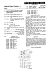
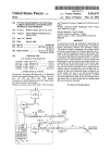
4. System design
4.6 Detector electronics
The detector electronics will amplify the signal from the
detectors, integrate the signal and hold the value until the
computer reads it. All this has to be done in
synchronisation with the laser.
Details about the detector electronic are found in
appendix 11.
4.6.1 Basic design
In the lorry the voltage is 12V. This voltage is
transformed on the circuit board to 5V that is used as
input by the components, see appendix 11.
The pulse from the detector has to be amplified. A
preamplifier does this, see figure 25.
The signal from the preamplifier is then integrated with a
standard integrator, see figure 26.
After the integrator the signal is again amplified by a
follower, see figure 27.
The mechanism to hold the signal until the computer can
read it is constructed by using the fact that there is a large
difference in energy between the laser pulse and the
background. The signal from the detector is almost zero
when there is no laser intensity.
The integrator will accumulate the signal from the time
when the trigger is received until the value can be read by
the computer, but since there is no output after the laser
pulse the circuit will "hold" the signal even though it is
integrated.
To reset the integrator a short circuit is put over the
integrating capacitor. This short-circuit is kept until the
low flank of the trigger signal is received, see figure 24.
The detector pulse is then integrated until the capacitor is
short-circuit again, see figure 28.
Short-circuit
pulse
74121
Trigger In
Figure 28 Short-circuit part.
Amplification= (R1 +R2)/R2
When the low flank is received in the trigger in, the
short-circuit is released and the capacitor can
integrate the signal.
The integration time= 0, 7*RC
Figure 25 Preamplifier.
4.6.2 Trimming the parameters
c
Output = -1/(RC)
Trimming the circuit parameters is done on the integrator
circuit. If one part is badly adjusted other parts can not
correct this error.
The dynamics in the system must be as big as possible at
the same time as no part should be saturated.
.fu dt
Figure 26 Integrator.
To be able to determine the values of the resistors and
capacitors an experiment was conducted on the detectors
with electronics, see appendix 18. This experiment
showed problems with offset and badly balanced
electronics. This is illustrated in figure 29. If the detector
electronics are not balanced the output value can increase
or decrease over time. It takes some time until the
computer reads out the value. During this time the value
can change, see figure 29. This will lead to errors in the
measurements.
Output= Rl/R2
Figure 27 Follower.
19
Department of Atomic Physics, Lund Institute of Technology