1
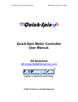
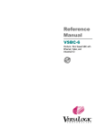
Friday, 21 June 2002
Final Report
Colin K McCord
From figure 5.3.1c (using -10 to 10V input) it is clear that a -10 to 10V sine-wave input has been applied and
the output is 0 to 5V. Figure 5.3.1d clearly shows a triangle-wave input of -5v to 5v, and an output of to 1.3V
to 3.70V. Notice the input and output waveforms are the same phase and polarity.
Figure 5.3.1c. Screen dump of oscilloscope (CH A: Input, CH B:
Output)
Figure 5.3.1d. Screen dump of oscilloscope (CH A: Input, CH B:
Output)
From figure 5.3.1e (using -50 to 50V input) it is clear that a -50 to 50V sinewave input has been applied and
the output is 0 to 5V. Figure 5.3.1f clearly shows a squarewave input of -25v to 25v, and an output of to
1.24V to 3.76V. Notice the input and output waveforms are the same phase and polarity.
Figure 5.3.1e Screen dump of oscilloscope (CH A: Input, CH B:
Output)
Figure 5.3.1f. Screen dump of oscilloscope (CH A: Input, CH B:
Output)
5.4. Analogue Circuit Diagram - Mark 2
Figure 5.4a shows the modified circuit diagram for ensuring that the input voltage falls between zero and five
volts, without the use of variable resistors. The first op-amp is designed to change the input voltage so that it
does not go over zero volts, for example changes -2.5 to 2.5V, to -5 to 0V. The second op-amp is configured
in negative amplifier mode with a gain of unity changing -5 to 0V to 0 to 5V. The third part with the two
diodes is for protection, e.g. say a -1 to 6V signal makes it through the op-amps the diodes will cut off the
peaks of the waveform making sure no damage is done to the PICs ADC. Note for the -250 to 250V range it
may be necessary for R3 to be made up of several resistors in series as standard resisters have a maximum
operating voltage of about 200 volts. All resistors should have a tolerance of at least 1%; ideally instrumental
resistors should be used.
Instead of three inputs it is recommend that a three-to-one line manual switch should be used to connect
each line to a single input line. Over voltage protection is still required in case of miss use, e.g. the user has
the -2.5 to 2.5V volt input selected and connects the 240VAC mains to the input.
EEE516J4 – Honours Project
Page 26
Chapter 5: Hardware Development