1
P3PC-3052-03ENZ0
fi-5950 Image Scanner
Operator's Guide
Function
Hoppe
Thin
r Height
Power
Thickn
ess
Thick
Send
to
Scan
INTRODUCTION
Thank you for purchasing the fi-5950 Image Scanner.
The fi-5950 is an image scanner designed to scan various documents in large quantities.
This document describes the basic operation methods to perform scanning by using ScandAll PRO.
The version of ScandAll PRO bundled with this product is subject to change without notice, in
which case the screenshots captured in this document may differ from the actual displayed image.
For more information about ScandAll PRO, refer to the separate [ScandAll PRO User's Guide].
The fi-5950 has the following features.
Improvement of color scanning speed (105 sheets or 210 pages
per minute) with high resolution (300dpi)
By the newly-developed high speed CCD and high speed image processing circuit,
scanning speed (A4 color, 300dpi) of 105 sheets/210 pages per minute) is improved.
Now you can scan a large amount of documents which is about 100,000 sheets a day!
Efficient pre-processing and post-processing!
This scanner is able to scan mixed documents stables of papers of different color,
density, size and thickness. This makes the scanning process even simpler and
economic, since you no not have to sort out the documents before scanning any more!
Furthermore, this scanner is equipped with an "Elevator" Stacker, moving
automatically into the appropriate height, according to the amount of loaded
documents. This will make the documents be easily and elegantly handled and also
increases your scanning efficiency!
Prevention of data loss because of improved multi feed detection
This scanner is equipped with ultrasonic multi feed detection sensors, which detect
reliably the feeding of 2 or more documents together into the scanner. Those multi
feed can also be detected surely, when scanning documents of different thickness,
size, color or density. This will help you to increase your efficiency, since the data loss
caused by multi feed is detected immediately. This gives you the opportunity to
correct the scanning without too much troubles and loss of time.
High image processing function
The automatic detection function of this scanner is able to detect if the loaded
documents are color or monochrome and according to the detection the appropriate
settings will be automatically chosen for the image creation. Since the scanner does
this automatically, you do not have to set the image settings each time before
scanning.
i
Pre- and Post imprinter option can be installed
In today's document business, imprinters provide a vital tool for archiving, controlling
and verification processes. For this scanner, you can select two optional types of
imprinters, depending on your needs. The Pre-Imprinter Option prints information on
the front side of the documents prior to the scanning. When using Pre-imprinter, the
printed information will also be stored on the generated image. The Post-Imprinter on
the other hand, will print after the scanning on the back sides of your documents. So
only the originals, and not the images, will contain the imprint.
Centralized management of multiple scanners
The bundled "Scanner Central Admin Agent" application allows you to manage
multiple scanners together, for example, to update the scanner settings and drivers, as
well as to monitor the operating status of each scanner.
About this manual
The manual provides the following information.
1. NAMES AND FUNCTIONS OF PARTS
This chapter describes names and functions of parts.
2. BASIC OPERATIONS
This chapter describes basic scanner operations and basic document scanning.
3. SCANNING VARIOUS TYPES OF DOCUMENTS
This chapter describes how to scan various types of documents.
4. DAILY CARE
This chapter describes how to clean the scanner.
5. REPLACING CONSUMABLES
This chapter describes how to replace consumables.
6. SOLVING COMMON PROBLEMS
This chapter describes how to remedy document jams, other trouble, and items to
check before contacting the agent where you bought the scanner, and how to check
device labels.
7. ADF DOCUMENT SPECIFICATIONS
This chapter describes documents that can be used with this scanner.
ii
8. SCANNER SETTINGS
This chapter explains the how settings can be done for the scanner using the Software
Operation Panel.
9. OPTIONS
This chapter describes the options available for this product.
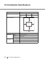
10. SCANNER SPECIFICATIONS
This chapter lists the scanner specifications.
The “Getting Started” is supplied to this Scanner.
This guide contains necessary information for getting started the scanner, also read the Getting
Started.
1. PREPARING THE SCANNER
This chapter describes how to prepare the scanner for use.
2. INSTALLATION OF THE SCANNER
This chapter describes how to install and connect the scanner, and how to install the
scanner application.
We hope that this manual is useful in taking full advantage of the fi-5950 Image Scanner features.
Trademarks
Microsoft, Windows, Windows Server, Windows Vista, and SharePoint are either registered
trademarks or trademarks of Microsoft Corporation in the United States and/or other countries.
ISIS is a registered trademark or trademark of EMC Corporation in the United States.
Kofax and VRS are either registered trademarks or trademarks of Kofax, Inc.
Other company names and product names are the registered trademarks or trademarks of the
respective companies.
iii
How Trademarks Are Indicated In This Manual
References to operating systems (OS) are indicated as follows:
Product
Indication
Windows® 2000 Professional
Windows 2000 Windows (*1)
Windows® XP Professional,
Windows® XP Professional x64 Edition,
Windows® XP Home Edition
Windows XP
Windows Server® 2003 Standard Edition,
Windows Server® 2003 Standard x64 Edition,
Windows Server® 2003 R2 Standard Edition,
Windows Server® 2003 R2 Standard x64 Edition
Windows
Server 2003
Windows Vista® Home Basic (32/64-bit),
Windows Vista® Home Premium (32/64-bit),
Windows Vista® Business (32/64-bit),
Windows Vista® Enterprise (32/64-bit),
Windows Vista® Ultimate (32/64-bit)
Windows Vista
Windows Server® 2008 Standard (32/64-bit),
Windows Server® 2008 R2 Standard
Windows
Server 2008
Windows® 7 Home Premium (32/64-bit),
Windows® 7 Professional (32/64-bit),
Windows® 7 Enterprise (32/64-bit),
Windows® 7 Ultimate (32/64-bit)
Windows 7
Windows Server® 2012 Standard (64-bit)
Windows
Server 2012
Windows® 8 (32/64-bit),
Windows® 8 Pro (32/64-bit),
Windows® 8 Enterprise (32/64-bit)
Windows 8
Microsoft® Office SharePoint® Portal Server 2003
SharePoint Server
Microsoft® Office SharePoint® Server 2007
Microsoft® SharePoint® Server 2010
*1 Where there is no distinction between the different versions of the above operating system, the
general term “Windows” is used.
iv
Manufacturer
PFU LIMITED
International Sales Dept., Imaging Business Division, Products Group
Solid Square East Tower, 580 Horikawa-cho, Saiwai-ku, Kawasaki-shi Kanagawa 212-8563, Japan
Phone: (81-44) 540-4538
© PFU LIMITED 2010-2013
■ Preface
Safety Precautions
The attached "Safety Precautions" manual describes important details for users to use this product
safely and correctly. Read the Safety Precautions thoroughly before you start using this product.
Warning Indications Used In This Manual
This manual uses the following indications to ensure safe and correct use of this product, and to
prevent possible danger and injury to the Operator and other persons.
WARNING
This indication alerts operators to an operation that, if not strictly observed,
may result in severe injury or death.
CAUTION
This indication alerts operators to an operation that, if not strictly observed,
may result in safety hazards to personnel or damage to equipment.
v
Symbols Used In This Manual
This manual uses the following symbols in explanations in addition to warning indications.
ATTENTION
This symbol alerts operators to particularly important information. Be sure
to read this information.
This symbol alerts operators to helpful advice regarding operation.
HINT
Screen Examples In This Manual
The screen examples in this manual are subject to change without notice in the interest of product
improvement.
If the actual displayed screen differs from the screen examples in this manual, operate by following
the actual displayed screen while referring to the User's Manual of the scanner application you are
using.
The screen examples used in this manual are of the TWAIN driver, ISIS driver, and ScandAll PRO
(image scanning application).
The Operator Panel Language Display
Apart from English, the operator panel can also display French, German, Italian, Spanish, and
Chinese (Simplified). In this manual, the language display of the operator panel is shown in English.
vi
CONTENTS
INTRODUCTION .......................................... i
Preface ................................................................................. v
1 NAMES AND FUNCTIONS OF PARTS....... 1
1.1 Names and Functions of Parts ......................................2
1.2 Operator panel ...............................................................5
2 BASIC SCANNER OPERATIONS ............... 7
2.1 Turning the Scanner ON /OFF .......................................8
2.2 Opening and Closing the Hopper ................................10
2.3 Opening and Closing ADF ...........................................12
2.4 Opening and Closing Top Cover .................................14
2.5 Setting the Hopper Height ...........................................15
2.6 Loading Documents on the Hopper .............................17
2.7 Setting up the Stacker .................................................22
2.8 Using the Document smoother ....................................27
2.9 Setting the Paper Thickness ........................................29
2.10 Scanning Documents .................................................30
2.11 Starting Scanning with Button ....................................35
2.12 Feeding Documents Manually ...................................36
2.13 Configuring the Scan Settings ...................................43
2.14 Before Using [Scan] / [Send to] button ......................60
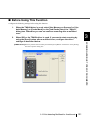
2.15 Resuming from Power Saving Mode .........................62
2.16 Image Scanning Application ......................................63
2.17 Centralized Management of Scanners ......................64
3 SCANNING VARIOUS TYPES OF
DOCUMENTS ............................................ 67
3.1
3.2
3.3
3.4
3.5
3.6
3.7
3.8
3.9
Double Sided Scanning ...............................................69
Scanning Documents Longer than A3 .........................70
Scanning Documents with different widths ..................72
Excluding a Color from the image (drop out color) ......75
Skipping blank Pages ..................................................78
Scanning the Image Brighter .......................................81
Detecting Multifeeds ....................................................84
Correcting skewed Documents ....................................86
Setting Auto Correction for Document Page
Orientations .................................................................88
vii
3.10 Multi Image Output ....................................................91
3.11 Color/monochrome Auto Detection ............................94
3.12 Not detecting Multifeed for fixed format .....................97
4 DAILY CARE............................................ 105
4.1
4.2
4.3
4.4
4.5
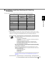
Cleaning Materials and Areas Requiring Cleaning ....106
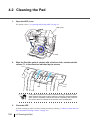
Cleaning the Pad .......................................................108
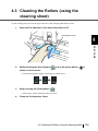
Cleaning the Rollers (using the cleaning sheet) ........109
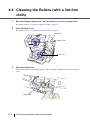
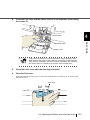
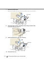
Cleaning the Rollers (with a lint-free cloth) ................112
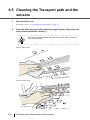
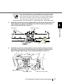
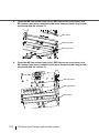
Cleaning the Transport path and the sensors ............116
5 REPLACEMENT OF CONSUMABLES ... 121
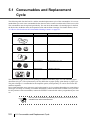
5.1 Consumables and Replacement Cycle ......................122
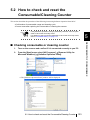
5.2 How to check and reset the Consumable/Cleaning
Counter ......................................................................123
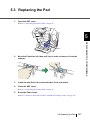
5.3 Replacing the Pad .....................................................127
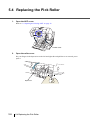
5.4 Replacing the Pick Roller ...........................................128
5.5 Replacing the Separator Rollers ................................130
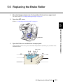
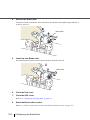
5.6 Replacing the Brake Roller ........................................133
6 SOLVING COMMON PROBLEMS .......... 135
6.1
6.2
6.3
6.4
6.5
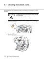
Clearing Document Jams ..........................................136
Error messages of the Operator panel ......................138
Troubleshooting .........................................................142
Before Contacting a Service Provider ........................155
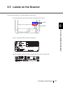
Labels on the Scanner ...............................................157
7 DOCUMENT SPECIFICATIONS.............. 159
7.1
7.2
7.3
7.4
7.5
7.6
7.7
7.8
viii
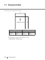
Document Size ..........................................................160
Document Quality ......................................................161
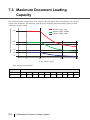
Maximum Document Loading Capacity .....................164
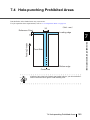
Hole-punching Prohibited Areas ................................165
Multifeed Detection Conditions ..................................166
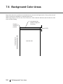
Background Color Areas ............................................168
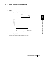
Job Separation Sheet ................................................169
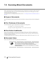
Scanning Mixed Documents ......................................170
8 SCANNER SETTINGS ............................. 173
8.1
8.2
8.3
8.4
8.5
Scanner Settings ......................................................175
Power saving setting ..................................................190
Offset/Scan scale .......................................................191
Multifeed Detection ....................................................193
Multifeed detection when scanning in manual feed
mode ..........................................................................198
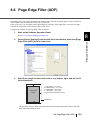
8.6 Page Edge Filler (ADF) ..............................................199
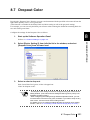
8.7 Dropout Color ............................................................201
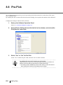
8.8 Pre-Pick .....................................................................202
8.9 Page Edge Filler
(Automatic Page Size Detection) ..............................203
8.10 Intelligent Multifeed Function ...................................205
8.11 Paper feeding retry times .........................................206
8.12 Retaining current paper thickness after Power off ...207
8.13 Cleaning Cycle .........................................................208
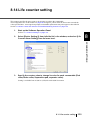
8.14 Life counter setting ..................................................209
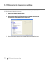
8.15 Document clearance setting ....................................210
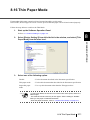
8.16 Thin Paper Mode .....................................................211
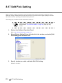
8.17 Soft Pick Setting ......................................................212
8.18 Paper Jam Detection ...............................................213
8.19 AutoCrop Boundary .................................................214
8.20 Auto Color Detection ................................................215
8.21 Alarm Setting ...........................................................216
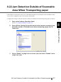
8.22 Jam Detection Outside of Scannable Area When
Transporting paper ...................................................217
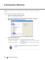
8.23 Imprinter Selection ...................................................218
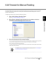
8.24 Timeout for Manual Feeding ....................................219
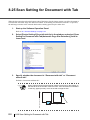
8.25 Scan Setting for Document with Tab .......................220
8.26 Paper Stop Position at Multifeed Error ....................221
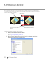
8.27 Overscan Control .....................................................222
9 OPTIONS ................................................. 225
9.1
9.2
9.3
9.4
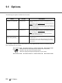
Options ......................................................................226
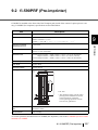
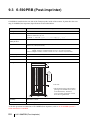
fi-590PRF (Pre-imprinter) ..........................................227
fi-590PRB (Post-imprinter) .........................................228
Other Options ............................................................229
ix
10 SCANNER SPECIFICATIONS................. 231
10.1 Basic Product Specifications ...................................232
10.2 Installation Specifications ........................................234
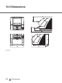
10.3 Dimensions ..............................................................236
INDEX
x
............................................................................IN-1
1
NAMES AND
FUNCTIONS OF PARTS
This chapter describes names and functions of various parts of the scanner.
1.1 Names and Functions of Parts..............................................2
1.2 Operator panel ........................................................................5
1
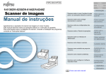
1.1 Names and Functions of Parts
This section describes the names of parts.
■ Front side
1
2
3
4
5
6
7
8
9
10
15
11
12
13
No.
2
14
Name
Function
1
Stopper
Prevents ejected documents from dropping off the scanner.
2
Stacker side guide
For aligning ejected documents to a certain width.
3
Top cover
Cover to access the consumables storage box and Post-Imprinter
option (sold separately).
4
Stacker
Documents will be ejected into the Stacker after scanning.
5
Ejector
For ejecting the documents after scanning.
6
Operator panel
For operating the scanner.
7
Stacker extension
For scanning long documents. Pull the extension out according to
the document’s length.
8
ADF cover
Open the cover for cleaning the inner parts of the ADF or for
replacing consumables.
9
ADF cover open button
Button used to open the ADF
10
Pre-imprinter cover
For the Pre imprinter option
11
ADF
(Automatic document feeder)
The documents loaded onto the Hopper will be fed sheet by sheet
for scanning.
12
Hopper extension
Pull the Hopper extension out for loading long documents.
13
Hopper
Documents to be scanned are loaded onto the Hopper.
14
Hopper side guides
Sheet Guides used to make sure that the paper to be scanned is
fed into the scanner straight, avoiding skew.
15
Power button
Switch the scanner ON&OFF.
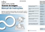
1.1 Names and Functions of Parts
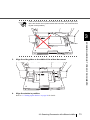
■ Rear side
1
2
1
No.
4
5
6
Name
7
NAMES AND FUNCTIONS OF PARTS
3
8
Function
1
Main power switch
For switching the power supply ON/OFF.
2
Power connector
For connecting the AC cable.
3
SCSI ID Switch
Sets the scanner’s SCSI ID.
4
SCSI connector
For connecting the SCSI cable.
5
USB connector
For connecting the USB cable.
6
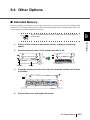
Extended memory
slot
For connecting an extension memory (sold separately). For details see
section 9.4.
7
VRS Board (optional)
slot
For connecting the VRS board (optional) to use Kofax VRS
(optional).
For details, refer to “9.1 Options” on page 226.
8
Extended slot
A spare slot for a third party board
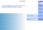
1.1 Names and Functions of Parts
3
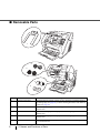
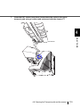
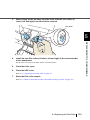
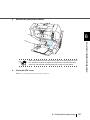
■ Removable Parts
Function
Hopper
Thin
Heig
ht
Power
Thickne
ss
Thick
Send
to
Scan
1
2
3
4
5
No.
4
Name
Description
1
Document smoother
Attached when the stacker position is set to align the ejected document by
the leading edge (see page 24), or when scanning documents with different
widths (see page 72).
2
Pick Rollers
Rollers that pick the paper from the hopper into the ADF. This is a consumable item.
3
Separator rollers
Roller used to help separate the paper as the feeding begins. This is a consumable item.
4
Brake rollers
Roller used to help separate the paper as the feeding begins. This is a consumable item.
5
Pad
Separation Pad used to help separate the paper as the feeding begins. This
is a consumable item.
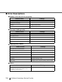
1.1 Names and Functions of Parts
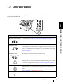
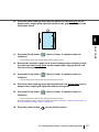
1.2 Operator panel
The operator panel is located on the right side of the scanner. The panel consists of a Function Number
Display, buttons and LEDs.
Function number display
Function
Hopper Height
Function
Hoppe
r Heig
ht
Thin
1
Powe
r Thickn
ess
Thick
Send
Paper Thickness
to
Scan
Thin
Send to
Scan
NAMES AND FUNCTIONS OF PARTS
Name
Thick
Function
Function Number display and Function button
Shows the status of the scanner.
For details, refer to "Indications on the Function Number Display" (page 6).
Function
Hopper height
adjustment button
Hopper Height
Document thickness
adjustment button
Paper Thickness
Thin
Use these buttons to adjust the height of the Hopper to the Upper/Middle/
Lower Positions.
The hopper moves automatically to the right position after recieving a scanning command. However, this may cause a delay before the actual scanning
starts. To avoid unnecessary waiting time, it is recommended to set the hopper height prior to scanning. For details, refer to “2.5 Setting the Hopper
Height” on page 15.
Use this buttons, to set the paper thickness of the documents.
(Normally no need to change from the default setting)
For details, refer to “2.9 Setting the Paper Thickness” on page 29.
Thick
[Send to] button
Send to
[Scan] button
Scan
Power button
Use this button to start linked application.
When this button is pressed at manual feed mode, the scanning stops immediately.
(* About the settings, refer to section “2.14 Before Using [Scan] / [Send to]
button” on page 60, or the TWAIN Driver help.)
Use this button to start linked application.
When this button is pressed during scanning operation, the scanning is cancelled.
(* About the settings, refer to section “2.14 Before Using [Scan] / [Send to]
button” on page 60, or the TWAIN Driver help.)
Use this button to turn the power ON/OFF.
When the power is turned on, the button is illuminated in blue.
1.2 Operator panel
5
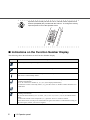
HINT
Operator Panel Overlays sheets in French, German, Italian, Spanish and
Chinese (Simplified) are provided with the scanner. To change the overlay,
open the plastic cover of the Operator Panel.
Thin
Send
tto
Scan
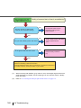
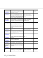
■ Indications on the Function Number Display
The following shows the indications on the Function Number Display.
No.
Descriptions
Lights only one time upon turning on the scanner.
Indicates that the scanner has been turned ON and is being initialized.
Indicates that initialization has been completed successfully.
This status is called “Ready Status”.
or
Indicates that a temporary error (that users can solve) has occurred during the initialization or
scanning of documents.
“J” or “U” and an error number (1, 2, 4, 6, 8, 0) are displayed alternately.
To return the scanner to the ready status (“1”), press the “Scan” or “Send to” button while the error
is indicated.
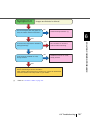
Indicates that a device alarm (that users can not solve) has occurred during the initialization or
scanning of documents.
“E” and an alarm number (0, 2 to 9, and A, c, d, F, 10 to 12, 15 to 19, 1A, 1b) are indicated alternately.
To return the scanner to the ready status (“1”), press the “Scan” or “Send to” button.
If this alarm occurs, turn the power off and then on again. If the alarm is indicated after turning on
the power again, contact your service engineer.
6
1.2 Operator panel
2
BASIC SCANNER
OPERATIONS
This chapter describes basic scanner operations.
This chapter explains operations using the screens of Windows XP.
Depending on your OS, your PC's screen shots and the operation may be
different from this manual. Be aware that when the TWAIN driver, or the
ISIS driver is updated, the screens and operations noted in this chapter may
be changed slightly. In this case, refer to the User's Guide provided with the
update.
2.1 Turning the Scanner ON /OFF ...............................................8
2.2 Opening and Closing the Hopper .......................................10
2.3 Opening and Closing ADF ...................................................12
2.4 Opening and Closing Top Cover.........................................14
2.5 Setting the Hopper Height ...................................................15
2.6 Loading Documents on the Hopper....................................17
2.7 Setting up the Stacker..........................................................22
2.8 Using the Document smoother ...........................................27
2.9 Setting the Paper Thickness ...............................................29
2.10 Scanning Documents.........................................................30
2.11 Starting Scanning with Button ..........................................35
2.12 Feeding Documents Manually...........................................36
2.13 Configuring the Scan Settings ..........................................43
2.14 Before Using [Scan] / [Send to] button ............................60
2.15 Resuming from Power Saving Mode ................................62
2.16 Image Scanning Application .............................................63
2.17 Centralized Management of Scanners..............................64
7
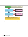
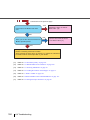
2.1 Turning the Scanner ON /OFF
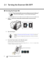
■ Turning the Power ON
ATTENTION
1.
When SCSI interface is used, turn on the scanner power first. Turn on the
PC when the scanner displays “1” on the Function number display.
Press “I” side of the main power switch located on the back of the
scanner.
OFF
2.
Open the Hopper.
HINT
3.
ON
• Refer to “2.2 Opening and Closing the Hopper” on page 10 to open the
Hopper.
• Be sure to open the Hopper before turning on the scanner by the Power
button.
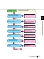
Press the Power button on the Operator panel.
The power turns on and the Power button lights up.
During initialization, the Function No. Display changes from “8” --> “P” to “1” in order. When
“1” shows, it means the scanner is ready.
Function number display
Thi
hin
Se
en
nd
d to
Scan
8
2.1 Turning the Scanner ON /OFF
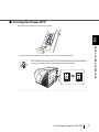
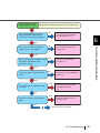
■ Turning the Power OFF
Hold the Power button for at least two seconds.
2
Thi
hin
Se
en
nd
d to
Scan
BASIC SCANNER OPERATIONS
⇒ The Power button light goes off and the scanner becomes disconnected.
HINT
If the scanner will not be used for an extended period, turn off the scanner’s
main power switch on the back and unplug the power cable.
ON
OFF
2.1 Turning the Scanner ON /OFF
9
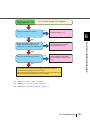
2.2 Opening and Closing the Hopper
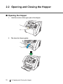
■ Opening the Hopper
1.
Hold the centrer of the upper part of the Hopper.
Function
Hopp
er Heig
ht
Pow
er Thic
kness
Thin
Thic
Sen
2.
d to
Scan
Flip down the Hopper gently.
p Heig
ht
Power
Thicknes
s
Thin
Thick
Send
to
Scan
Function
Hopp
Thin
Pow
er Thic
er Heig
knes
ht
s
Thic
Sen
10
2.2 Opening and Closing the Hopper
d to
Scan
k
k
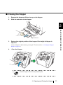
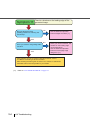
■ Closing the Hopper
1.
Remove the document if there is any on the Hopper.
2.
Slide the extension in the Hopper.
2
BASIC SCANNER OPERATIONS
Hopper extension
3.
Restore the original position of the hopper if the height of Hopper is
adjusted.
Lower the hopper to the bottom by pressing the
Height” on page 15)
4.
button. (Refer to “2.5 Setting the Hopper
Close the Hopper.
Function
Function
Hopper
Hopper
Thin
Thin
Height
Heig
ht
Power
Thickne
ss
Power
Thic
kness
Thick
Thick
Send
Send
to
Scan
to
Scan
ATTENTION
Push the hopper until it’s securely locked in place.
2.2 Opening and Closing the Hopper
11
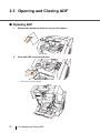
2.3 Opening and Closing ADF
■ Opening ADF
1.
Remove the document if there is any on the stacker.
Function
Hopper
Heig
Thin
Power
Thic
ht
kness
Thick
Send
to
Scan
2.
Press the ADF cover open button.
Function
Hopper
Heih
gt
Thin
Power
Thi
cknes
s
Thick
Send
to
Scan
⇒ The cover is slowly opened.
12
2.3 Opening and Closing ADF
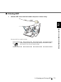
■ Closing ADF
1.
Hold the ADF cover with both hands and press it down slowly.
2
BASIC SCANNER OPERATIONS
Press the ADF cover until it is fixed.
ATTENTION
• When closing the ADF, make sure that nothing is left inside the ADF.
• Be careful not to have your fingers caught.
2.3 Opening and Closing ADF
13
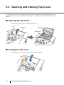
2.4 Opening and Closing Top Cover
Under the Top cover, there are a storage tray for storing the consumables and cleaning goods and a space
for installing the Post-Imprinter. When you use the tray or access the Post-Imprinter, open the top cover as
follows.
■ Opening the Top Cover
Press the tabs of the Top cover and open the top cover.
Tab
Top cover
Top cover
Storage tray
Space for installing the Post-Imprinter
■ Closing the Top cover
Close the Top cover and press lightly until it is fixed with the tab.
14
2.4 Opening and Closing Top Cover
2.5 Setting the Hopper Height
When there is no alarm (the function number display is showing “1”), the Hopper height can be adjusted.
When the scanning load is not very heavy, setting the hopper higher will shorten the time it moves to the
feeding position.
ATTENTION
Adjustment is not possible when:
•The scanner is scanning
•The hopper is closed.
•When using Software Operation Panel (see page 175).
Three hopper heights are available and the corresponding capacities are as follows.
High:
Up to 100* sheets
Middle:
Up to 300* sheets
Low:
Up to 500* sheets
*: Estimated using paper of 80g/m2 (20lb).
High
Middle
Low
HINT
Depending on the thickness of the document, the loading capacity differs.
Refer to “7.3 Maximum Document Loading Capacity” on page 164.
2.5 Setting the Hopper Height
15
2
BASIC SCANNER OPERATIONS
• Do not touch the hopper when it is being adjusted. Your finger(s) may
be pinched.
• Do not load anything onto the hopper when it is moving. If something
gets into the mechanism, the scanner may be damaged.
• Do not place anything under the hopper. The hopper may collide with it
and become damaged.
• Do not press the [Hopper Height] button (
) when the hopper is
closed. The hopper may be damaged.
The adjustment is done by using the Operator Panel on the scanner.
Function
Hopper Height
Functio
n
Hoppe
r Heigh
t
Thin
Powe
r Thick
ness
Thick
Send
to
Scan
Paper Thickness
Thin
Thick
Send to
Scan
button, the hopper is raised one step higher.(Low
When you press the
When pressing the
button, the hopper is lowered one step lower.(High
Middle
Middle
High)
Low)
Immediately after the scanner is turned on, the Hopper is initially set to Low.
HINT
16
2.5 Setting the Hopper Height
2.6 Loading Documents on the Hopper
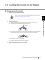
■ Preparing the Document
1.
Align both edges of the documents.
HINT
For how to scan the document with different widths, refer to “3.3 Scanning
Documents with different widths” on page 72.
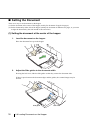
2
Fan the documents.
1)
Take a stack of documents about 15mm to 20mm thick (1/2 to 3/4 inch).
2)
Hold both ends and bend the documents into an arch.
15 to 20mm
3.
3)
Firmly holding the document with both hands, bend back the document as follows
so that the bent section rises up in the middle of the document as follows.
4)
Repeat steps 1) to 3) for a few times.
5)
Rotate the document 90 degrees, and fan again.
Align the leading edges of the documents.
2.6 Loading Documents on the Hopper
17
BASIC SCANNER OPERATIONS
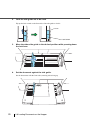
2.
■ Setting the Document
There are 2 ways to set documents on the hopper.
(1) Set the document at the center of the hopper (mainly for document of equal size pages).
(2) Set the document by either side of the hopper (mainly for document of different size pages, or you want
to align the document by the side instead of the center line).
(1) Setting the document at the center of the hopper
1.
Load the document on the hopper.
Place the document face-up on the hopper.
2.
Adjust the Side guides to the document width.
Pressing the lock lever, slide the Side guides so that they contact the document sides.
If there is space between the document edges and the guides, the scanned images may be
skewed.
Side guide
18
2.6 Loading Documents on the Hopper
Lock lever
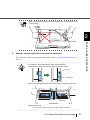
ATTENTION
• Make sure that the document stack does not exceed the maximum
height mark on the inner side of the Side guides.
• For long documents, use the hopper extension.
height mark
2
BASIC SCANNER OPERATIONS
Hopper extension
3.
Start the scanner application and scan the document.
For the details on how to scan using ScandAll PRO, refer to “2.10 Scanning Documents” on
page 30.
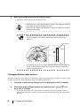
(2)Setting the document by either Side Guide of the hopper.
For scanning documents with pages of different sizes, see section “7.8 Scanning Mixed
Documents” on page 170.
1.
Move the hopper side guides to their outermost positions.
Side Guide
2.6 Loading Documents on the Hopper
19
2.
Lock the side guide not to be used.
Flip up the lock switch on the front side of the side guide to lock it.
Locked!
Lock Switch
3.
Move the other side guide to the desired position while pressing down
the lock lever.
サイドガイド
4.
Set the document against the side guide.
Set the documents with the front side (scanning side) facing up.
20
2.6 Loading Documents on the Hopper
ATTENTION
Make sure that all the pages fall under the pick roller. (Otherwise they will
not be picked)
2
5.
BASIC SCANNER OPERATIONS
Pick roller
Start the scanner application and scan the document.
For the details on how to scan using ScandAll PRO, refer to “2.10 Scanning Documents” on
page 30.
HINT
If you want to unlock side guides, follow the steps below:
1.Release the locked side guide by flipping down the switch.
Unlocked!
Lock Switch
2.Move both side guides toward the center while pressing the lock lever.
ロックスイッチ
Lock Lever
3.Release the lever.
⇒ Now the two sides will move symmetrically as before.
2.6 Loading Documents on the Hopper
21
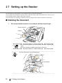
2.7 Setting up the Stacker
The document set on the hopper, once scanned, will be ejected onto the stacker.
You can adjust the inclination of Stacker table to align the leading edge of document or not. Also you can
fix the height of Stacker table for thin paper stacking.
Set up the Stacker by adjusting the Stacker extension, Stopper, Side Guides and Stacker's inclination.
■ Stacking the document
1.
Pull out the stacker extension in accordance with document length.
Stacker extension
Stopper
Function
Hopper
Thin
Height
Power
Thickne
ss
Thick
Send
to
Scan
ATTENTION
• Do not use the stopper to pull out the stacker extension. It may be damaged.
• Be sure to extend the stopper longer than the document.
For short documents, use the small stopper.
HINT
Small Stopper
22
2.7 Setting up the Stacker
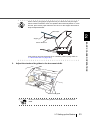
HINT
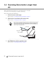
When scanning long pages (longer than A3), the document may be longer
than the stacker extension even if it’s pulled to the outermost position. In case
like this, place a thick paper about the size of A4 on the stopper and make a
slope as depicted below.
Thick Paper
2
Stopper
BASIC SCANNER OPERATIONS
Stacker Extension
(The scanner can scan document up to 3,048mm (120inch) long. Refer to
“7.1 Document Size” on page 160.)
2.
Adjust the stacker side guides to the document width.
Stacker side guide
ATTENTION
Be sure to set the stacker side guides a little wider than the document
width.
2.7 Setting up the Stacker
23
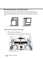
■ Changing Stacker inclination/motion
The location of the stacker can be switched when ejecting documents by fixing the stacker height in the
appropriate position, or by using either the horizontal setting for bottom edge alignment or the tilting forward setting for leading edge alignment. The factory default is set to the horizontal setting. When using the
tilting forward setting for leading edge alignment, follow the procedure below to switch the position of the
stacker.
Bottom edge alignment by
horizontal stacker setting
Leading edge alignment by tilting
forward setting of stacker
<Switching to the tilting forward setting>
1.
Slide the stacker out towards you.
2.
Push down the part of the stacker which is closer to you.
ԙ
後端
ԙ
え
Ԙ
⇒ The stacker inclines towards you.
24
2.7 Setting up the Stacker
先端
え
Ԙ
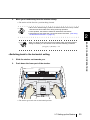
3.
Move your hands away from the stacker slowly.
⇒ The stacker will be fixed in a position tilting forward.
• When set to “Bottom edge” position, the stacker does not move up or down
and becomes immovable even during scanning operation.
• In this position, the stacker’s maximum load will be 200 sheets.
• If the pages do not stack well, use the Document Smoother. (“2.8 Using
the Document smoother” on page 27)
HINT
2
BASIC SCANNER OPERATIONS
When you align the documents from the leading edge (by tilting forward
setting of stacker), the documents must meet the following conditions:
ATTENTION
( Length ) ÷ ( Width ) < 1.5
<Switching back to the horizontal setting
1.
Slide the stacker out towards you.
2.
Push down the inner part of the stacker.
ԙ
Ԙ
ԙ
Ԙ
⇒ The stacker goes back into its horizontal position.
2.7 Setting up the Stacker
25
3.
Move your hands away from the stacker slowly.
⇒ The stacker will be fixed in a horizontal position.
HINT
ATTENTION
• When set to the “bottom edge alignment” position, the stacker will automatically adjust its height according to its load.
• When set to the “Bottom edge alignment” position, the stacker’s maximum
load will be 500 sheets.
• On both sides walls of the stacker, photo sensors are installed to detect
document height on the stacker. Make sure these sensors are not
blocked.
Photo sensors
Thin
Send
Pow
er
to
• The stacker may move up or down when the scanner is in the ready status up or when scanning starts. Do not touch the stacker or place anything on it at those times.
<Changing Stacker table motion>
Thin paper sometimes curles when it is ejected to the stacker. This method may be effective to improve the
stacking capability by fixing the stacker hight in the appropriate position.
1.
Close the scanner driver dialog box if it is displayed on the PC monitor.
2.
Press both Hopper Height buttons on operator panel (
more than 2 seconds.
and
) for
⇒ Every time this is done, the stacker table moves between the lowest position and the
position little a bit above. Set the stacker table at the position little a bit above the lowest
position.
26
2.7 Setting up the Stacker
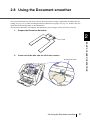
2.8 Using the Document smoother
The ejected document may not stack correctly when the stacker’s angle is adjusted to the tilting forward
setting (see page 24), or when scanning document of different size pages (see page 72). If that is the case,
install the Document Smoother as described below.
The Document Smoother will suppress the splattering of ejected pages so they will stack correctly.
1.
Prepare the Document Smoother.
2
Tab
BASIC SCANNER OPERATIONS
2.
Insert one of the tabs into the slit in the scanner.
Document Smoother
Function
Hopp
Thin
er Heig
ht
Power
Thicknes
s
Thick
Send
to
Scan
2.8 Using the Document smoother
27
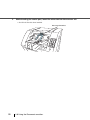
3.
While bending the center part, insert the other tab into the scanner slit.
⇒ It will look like this when installed.
Document Smoother
Function
Hopper
Heig
ht
Thin
Power Thic
kness
Thick
Send to
Scan
28
2.8 Using the Document smoother
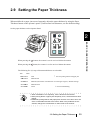
2.9 Setting the Paper Thickness
When multifeeds or paper jam occurs frequently, adjust the paper thickness by using the Paper
Thickness button on the operator's panel. (Under normal circumstances, use the default setting.)
Set the paper thickness on the Operator Panel.
Function
2
Hopper Height
Function
Hoppe
r Heig
ht
Thin
Powe
r Thickn
ess
Thick
Send
to
Scan
BASIC SCANNER OPERATIONS
Paper Thickness
Thin
Thick
Send to
Scan
When pressing the
button, the scanner is set for one level thicker document.
When pressing the
button, the scanner is set for one level thinner document.
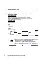
The following five (5) steps of document thickness are selectable.
Thin
HINT
Thick
:
Thin
Prevent picking failure and paper jam
:
Medium thin
:
Medium (Documents with thickness of 52 through 127g/m2) <Default setting>
:
Medium thick
:
Thick
Prevent multifeeding
• When multifeeds occur frequently, set the thickness level thicker.
• When picking failure or paper jams frequently occur, set the thickness level
thinner.
• Multifeeds, picking failures and paper jams can also occur due to worn-out
of the consumables and dirt of the rollers. When such problems are not
cleared, change the consumables or clean inside of the scanner.
2.9 Setting the Paper Thickness
29
2.10 Scanning Documents
This section explains about the basic flow of scanning operations.
In order to use the scanner to scan documents, you need a scanner driver and an application that supports
the driver.
This product bundles the TWAIN driver and the ISIS driver (compliant to the respective standards), and an
application called "ScandAll PRO" which supports both drivers.
HINT
1.
• For details about the scanner drivers, refer to the following:
- “2.13 Configuring the Scan Settings” on page 43
- TWAIN Driver Help
- ISIS Driver Help
• For details about ScandAll PRO, refer to the following:
- ScandAll PRO User's Guide
- ScandAll PRO Help
Load the documents on the hopper.
Refer to the section “2.6 Loading Documents on the Hopper” on page 17.
2.
Adjust the stacker table to the document size.
ATTENTION
30
• When loading long documents on the hopper, extend the stacker extension.
• When loading short documents on the hopper, adjust the stacker length
with the small stopper.
2.10 Scanning Documents
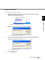
3.
Start up the application to use for scanning.
ScandAll PRO will be used here as an example to explain the procedure.
When ScandAll PRO is launched
2
For information on how to launch ScandAll PRO, refer to "ScandAll PRO User's Guide".
Select a scanner driver to use for scanning.
BASIC SCANNER OPERATIONS
4.
2.10 Scanning Documents
31
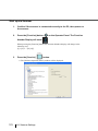
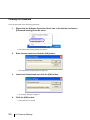
5.
Select a scanner.
For TWAIN Driver
For ISIS Driver
32
2.10 Scanning Documents
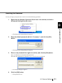
6.
Launch a scanner driver from the application.
2
BASIC SCANNER OPERATIONS
For TWAIN Driver
For ISIS Driver
2.10 Scanning Documents
33
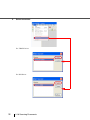
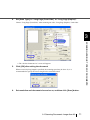
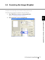
7.
In the scanner driver’s setup dialog box, configure the scan settings.
8.
Perform a scan.
For information on how to scan using ScandAll PRO, refer to "ScandAll PRO User's Guide".
9.
Save the scanned images in a file.
HINT
34
Procedures and operations slightly vary depending on the application used.
For details about how to scan using ScandAll PRO, refer to "ScandAll PRO
User's Guide".
To perform scanning with other applications, refer to the manual bundled
with the application.
2.10 Scanning Documents
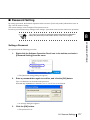
2.11 Starting Scanning with Button
Pressing the [Scan] / [Send to] button can start an application previously linked.
However, you need to set the application for [Scan] and [Send to] button referring to “2.14 Before Using
[Scan] / [Send to] button” on page 60.
1.
Load the documents on the hopper.
Refer to the section “2.6 Loading Documents on the Hopper” on page 17.
2.
Adjust the stacker table to the document size.
2
Refer to “2.7 Setting up the Stacker” on page 22.
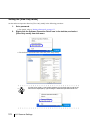
Press the [Scan] or [Send to] button.
When using the [Scan] button, press the button.
When using the [Send to] button, you can set from [Send to 1 to 9] of nine (9) kinds of settings.
Each pressing the [Function] button increases the number of Function Number display as 1
3.... Set the number that links the application software you want to use for scanning and
press the [Send to] button.
Function Number display
2
[Function] button
Function
Hopper Height
Function
Hoppe
r Heig
ht
Thin
Powe
r Thickn
ess
Thick
Send
to
Scan
Paper Thickness
Thin
Thick
Send to
Scan
⇒ The application previously set for the number is started.
ATTENTION
If the [Send to] button is pressed when "C" is displayed in the Function
Number Display, the Software Operation Panel will start (see page 175).
2.11 Starting Scanning with Button
35
BASIC SCANNER OPERATIONS
3.
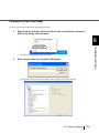
2.12 Feeding Documents Manually
Besides the “Automatic Feed Mode” which automatically scans the document set on the hopper, the scanner can also scan documents in the “Manual Feed Mode”.
In addition, the “Manual Feed Mode” is divided into 2 types:
<1> Single Feed: Only one sheet is manually fed and scanned. This is
suitable for
•thick paper, envelopes and folded paper and other types of documents that are difficult to
scan using Automatic Feed Mode. (In case of folded paper, make the folding line as the
leading edge).
•reducing the load on the hopper.
•making sure a certain page is scanned.
<2> Continuous Feed: Multiple sheets of document are manually fed
one at a time and continuously scanned. This is suitable for
•manual feed, even if multiple sheets are mistakenly fed, the scanner will scan one at a
time.
•selectively scanning a stack of document.
•making sure certain pages are scanned.
The procedure is described below.
36
2.12 Feeding Documents Manually
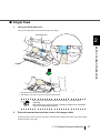
■ Single Feed
1.
Lift up the Pick roller unit.
Lift up the small plate on the left side using your finger.
Pick Roller Unit
2
BASIC SCANNER OPERATIONS
Hopper
⇒ The Pick roller unit will click into place.
⇒ The hopper will move up to the manual feed position.
ATTENTION
2.
• If there is any document loaded on the Hopper, remove it before
adjusting.
• Be careful not to get your fingers or anything caught in the mechanism
when the hopper table moves up.
Place documents face-up at the center of the hopper table.
At this moment, do not stick the top edge of the document against the inner side of the hopper,
instead set them a bit apart.
2.12 Feeding Documents Manually
37
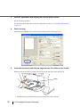
3.
Start the application and display the scanner driver screen.
Set the scanning condition.
For the information about how to run the scanner driver, refer to “2.10 Scanning Documents”
on page 30.
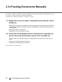
4.
Start scanning.
When using the TWAIN driver, click the [Scan] button on the following screen.
5.
Insert the document until the top edge touches the rollers on the inside.
When more than one sheet is loaded, only the one on the top of the stack will be fed.
Roller
⇒ The document is picked up and ejected onto the stacker after scanning.
38
2.12 Feeding Documents Manually
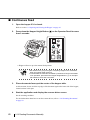
6.
Repeat the procedure 5 until all the documents are scanned.
After a certain time period of inactivity or at pressing of [Send to] button, the scanner will
recognize it as “no document” and stop scanning.
HINT
For setting the timeout for feeding the document manually, refer to section
“8.24 Timeout for Manual Feeding” on page 219.
2
To deactivate “Manual Feed Mode” (Single Feed), return the Pick roller
unit to its original position.
BASIC SCANNER OPERATIONS
7.
Flip down the small plate on the left using your finger.
Pick Roller Unit
2.12 Feeding Documents Manually
39
■ Continuous Feed
1.
Open the hopper if it is closed.
Refer to section “2.2 Opening and Closing the Hopper” on page 10.
2.
Press down the Hopper Height Button ( ) on the Operator Panel for more
than 3 seconds.
Function
Hopper Height
Functio
n
Hoppe
Thin
r Heig
ht
Powe
r Thick
ness
Thick
Send
to
Scan
Paper Thickness
Thin
Thick
Send to
Scan
⇒ Hopper will move up to the manual feed position.
ATTENTION
3.
• Be careful not to get your fingers or anything caught in the mechanism
when the hopper table moves up.
• To deactivate the “Manual Feed Mode” (Continuous Feed) in the middle
of an operation, press down the Hopper Height Button ( ) on the Operator Panel for more than 3 seconds.
Place documents face-up at the center of the hopper table.
At this moment, do not stick the top edge of the document against the inner side of the hopper,
instead set them a bit apart.
4.
Start the application and display the scanner driver screen.
Set the scanning condition.
For the information about how to run the scanner driver, refer to “2.10 Scanning Documents”
on page 30.
40
2.12 Feeding Documents Manually
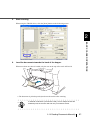
5.
Start scanning.
When using the TWAIN driver, click the [Scan] button on the following screen.
2
BASIC SCANNER OPERATIONS
6.
Load the documents towards the back of the hopper.
When more than one sheet is loaded, only the one on the top of the stack will be fed.
⇒ The document is picked up and ejected onto the stacker after scanning.
HINT
In “Manual Feed Mode” (Continuous Feed), even if multiple sheets are
mistakenly fed, the scanner will scan only one sheet at a time.
2.12 Feeding Documents Manually
41
7.
Repeat the procedure 6 until all the documents are scanned.
⇒ After a certain time period of inactivity or at pressing of [send to] button, the scanner will
recognize it as “no document” and stop scanning.
HINT
8.
42
For setting the timeout for feeding the document manually, refer to section
“8.24 Timeout for Manual Feeding” on page 219.
To deactivate the “Manual Feed Mode” (Continuous Feed), press down
the Hopper Height Button ( ) on the Operator Panel for more than 3
seconds.
2.12 Feeding Documents Manually
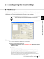
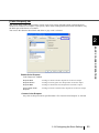
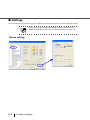
2.13 Configuring the Scan Settings
■ TWAIN Driver
The TWAIN driver is a software driver that conforms to the TWAIN standard. This driver can be used with
an application that supports TWAIN to perform scanning.
Normally, the scanner driver is launched via an application, and then the scan settings are configured in the
setup dialog box of the driver (some applications may not display the setup dialog box).
2
Ways to launch the scanner driver differ depending on the application.
For more details, refer to the manual or the Help files of the application.
HINT
BASIC SCANNER OPERATIONS
Main screen
You can perform settings for the TWAIN Driver on this window.
The following describes the main setting items.
•For details on each functions, refer to “TWAIN Driver Help” (appears by pressing
[Help] or [F1] button).
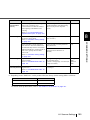
Resolution
Specifies the resolution of scanning.
It can be specified by selecting a default value from the list or customizing (specifies any
resolution in 1 dpi unit, within a range of 50 to 600 dpi ).
By marking the [Predefine] checkbox, you can select one from three predefined settings as
[Normal], [Better], [Best] to scan documents instead of setting details by yourself.
Otherwise, you can change the details of the predefined settings on the [Resolution Setting]
window, which appears when you click on the [...] button.
2.13 Configuring the Scan Settings
43
Scan Type
Specifies the feeding method, the side(s) to be scanned (Front Side, Back Side, Duplex) or
details of Long page (Front Side, Duplex) details of Long page (Front Side, Duplex) *.
* Refers to documents larger than Double Letter (11 × 17 in.)/A3.
Paper Size
Select the size of documents to be scanned from this list.
Windows for customizing the paper size will appear when you click on [...] besides the list. You
can save any document size as a customized setting (up to three) or for changing the order of the
paper size in the list.
Image Mode
Specifies the image type for the scanned documents.
Black & White
Documents are scanned in binary (black and white).
Halftone
Documents are scanned with halftone processing in black and white.
Gray scale
Documents are scanned in gradations from black to white. For this
mode you can select 8 bit (256 gradations) or 4 bit (16 gradations).
Color
Documents are scanned in color. For this mode, you can select 24 bit
Color, 256 bit Color or 8bit Color.
SEE
(Selectable Edge
Enhancement)
Documents with line drawings and photographs are scanned using
halftone processing, and only the line drawings and text are emphasized.
This mode is most suitable for emphasizing only text of documents
containing both photographs and text.
[Scan] button
Starts scanning documents with the current settings.
[Preview] button
Documents are scanned preliminarily before the actual scanning.
You can confirm the image of the documents in the preview window.
[Close] button
Saves the current settings and closes this window.
[Reset] button
Used to undo changes of settings.
[Help] button
Opens the “TWAIN Driver Help” window. The window also opens by pushing the [F1] key.
[About...] button
Opens an information window about the TWAIN Driver's version.
44
2.13 Configuring the Scan Settings
[Option...] button
You can set up the details of optional functions on the window below.
2
BASIC SCANNER OPERATIONS
[Rotation] tab
Select this tab when setting items such as flip side rotation, image rotation, hole punch removal,
skew correction, size and length detection, black background, and overscan.
[Job/Cache] tab
Select this tab when setting cache mode, job controls, multifeed detection, blank page skipping,
etc.
[Imprinter (Endorser)] tab
Select this tab when setting printing configuration for imprinter (sold separately). Only shows
when an imprinter is installed.
[Generic] tab
Select this tab to change the unit displayed on the Setting Window for the TWAIN Driver.
(Millimeters, Inches, and Pixels are available)
[Startup] tab
Select this tab for setting the Scanner Operation Panel.
[Filter] tab
Select this tab for setting the image processing filter(s).
Page Edge Filler: Fills up the margins of the scanned documents with a selected color.
Digital Endoser: A character string, such as the alphabet and numbers, can be added in the
scanned document.
[Compression] tab
Select this tab for setting the compression rate of JPEG Transfer.
[Advance...] button
Click this button for settings of the advanced image processing.
You can set Edge Extract, Gamma Pattern, White Level Follower, Dropout Color, Reverse, etc.
2.13 Configuring the Scan Settings
45
[Config...] button
Click this button for configuring the Setting Files.
You can save the changed settings as a Setting File. From next scanning, the settings are quickly
changed by using these Setting Files.
For details of each function, refer to the “TWAIN Driver Help”.
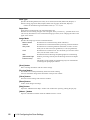
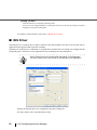
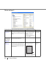
■ ISIS Driver
The ISIS driver is a software driver which conforms to the ISIS standard. This driver can be used with an
application that supports ISIS to perform scanning.
Normally, the scanner driver is launched via an application, and then the scan settings are configured in the
setup dialog box of the driver (some applications may not display the setup dialog box).
HINT
Ways to launch the scanner driver differ depending on the application.
For more details, refer to the manual or the Help files of the application.
Settings for the ISIS driver are configured in the above dialog box.
For more details, refer to the ISIS Driver Help.
46
2.13 Configuring the Scan Settings
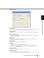
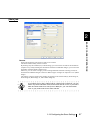
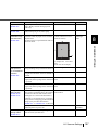
[Main] tab
2
BASIC SCANNER OPERATIONS
Camera
Selects the document’s side (front or back) to be scanned.
The check-marked side(s) will be scanned.
By marking only the checkbox(es) of Front Image, you can scan the one side of the documents
(simplex scan), and by marking the checkboxes of both Front and Back Images, you can scan the
both sides of the documents (duplex scan).
Moreover, you can select color/gray scale scanning and black and white scanning (#1/#2) for
both the Front and Back Images so that two different types of images are output at a scan. (Multi
Image)
The settings you have made on this window are applied to the selected side(s) (Front Image #1,
Front Image #2, Back Image #1, and/or Back Image #2).
HINT
If you select color or gray scale mode for a side (Front or Back) #1, you can
select only black and white mode for the same side #2. In turn, if you select
black and white mode for a side (Front or Back) #1, you can select either
color or gray scale mode for the same side #2.
2.13 Configuring the Scan Settings
47
Mode
Select a color mode suitable for the purpose from the menu.
Image Processing
Scans data in binary (black and white) using Image Processing Software Option. When this mode is selected, the [Setup IPC...] button
below becomes available.
(Note that only when Image Processing Software Option is installed in
the computer, it is displayed.)
Black and White
Scans data in binary (black and white). Distinguishes black from white
according to the fixed threshold. This scanning mode is suitable for
scanning line drawings and text documents.
16-level Gray
Scans data with 16 gradations from black to white. This mode uses 4
bits per pixel.
256-level Gray
Scans data with 256 gradations from black to white. This mode uses 8
bits per pixel.
24-bit Color
Scans data as full-color images using 24 bits per pixel. This mode is
suitable for scanning color photographs. However, more memory space
is needed compared to gray scale scanning.
Auto Detect 16-/256- Distinguishes between color data and black and white data, and outputs
documents as they are; that is, color data is output in color (or gray
level, Auto Detect
24-bit Color
scale) mode and white and black data is output in black and white
mode.
Configure settings for color documents using Front/Back Image #1, and
for black and white documents using Front/Back Image #2, under
“Camera”.
[Setup IPC] button
You can configure settings for scanning with Image Processing Software Option.
HINT
For details on how to configure settings for Image Processing Software
Option, refer to "Image Processing Software Option User's Guide".
To display the "Image Processing Software Option User's Guide", select
[Start] > [All Programs] > [Image Processing Software Option] > [User's
Guide].
Dots per inch
Specifies the number of pixels (dots) per inch.
Select a fixed resolution from the list or input a number from 50 to 600.
The higher the resolution, the more memory is required.
48
2.13 Configuring the Scan Settings
Dither
Select the halftone pattern for halftone scanning. This setting is available when “Black and
White” is selected in the “Mode”.
Pattern 1
Pattern 2
Pattern 3
Pattern 4
Error Diffusion
This setting is suitable for scanning dark photographs.
This setting is suitable for scanning dark-colored documents containing
both text and photographs.
This setting is suitable for scanning light photographs.
This setting is suitable for scanning light-colored documents containing
both text and photographs.
This function minimizes the differences of color levels.
2
Cropping
Fixed
Detect Length
Automatic
Deskew
Long page
BASIC SCANNER OPERATIONS
Select how to crop scanned documents to output.
Outputs the document in the specified size.
Detects the rear end of the document to scan the whole length of the
document. When shorter pages are included in the document, the output
images of them are adjusted to the original size.
Automatically detects the paper size of the document and outputs in the
original size. In addition, document skews are automatically detected
and corrected to output the image data.
Corrects document skews after scanning to output correct image data.
Scans long documents and outputs the deskewed / cropped image data.
Brightness
Sets the brightness of the entire image. Specify the brightness as a number within the range of 1
(dark) to 255 (bright). To brighten the entire image, increase the value of the setting. To darken
the entire image, decrease the value.
Contrast
Sets the contrast between light and shadow of the scanned image. Specify the contrast as a
number within the range of 1 (low [soft]) to 100 (high [sharp]). Increasing this value makes the
contrast sharper.
2.13 Configuring the Scan Settings
49
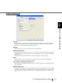
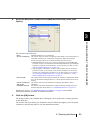
[Layout] tab
Page Orientation
Specifies the page orientation (Portrait or Landscape).
Paper Size
Selects a paper size according to the size of the document to be scanned. Select any size from the
list.
[Scan Area...] button
Opens the [Scan Area] dialog box.
You can specify the area to be scanned.
50
2.13 Configuring the Scan Settings
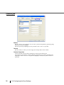
[Image Processing] tab
2
BASIC SCANNER OPERATIONS
Quick Set
You can select a preset pattern for image enhancement. By selecting the one from the list, you
can quickly set the details of the image enhancement processing. Available patterns are as
follows:
Normal documents
(default)
This item is suitable for scanning the documents like the ones used
in offices.
Advanced DTC
This option scans any kind of documents by binary processing to
produce data with good scanning quality.
Documents containing thin letters, characters with the colored
background, and colored charts cannot be scanned sufficiently
clearly by ordinary binary processing. By using this option, however, you can achieve good scanning quality.
Background/Foreground Enhancement
This option makes image contours soft by disabling the Outline
Extraction, and the whole image blurs.
NCR forms with background removed
This option removes background of scanned images and smooths
outline, giving an effect of anti-aliasing on the images.
Cleanup noisy documents
This option removes noise on the data.
Magazines, Brochures,
etc.
This option is suitable for scanning documents which have texts
and photos (e.g. magazines, brochures).
Reverse Image Format
Converts colors from/to negative to/from positive.
2.13 Configuring the Scan Settings
51
Overscan
Scans the document allowing more margins than the ones of paper size specified at [Paper
Size:]. Thus, the result of scanning is bigger than the specified paper size.
Image Emphasis
This option processes the outline of the scanned image as follows:
Low, Mid, High
Emphasizes the contour of images. You can select the degree of
emphasis from low, mid, and high.
Smooth
Smooths jaggy images.
White Level Follow
Use this option when the basic color of documents is not white; for example, when scanning
newspaper.
Auto
Automatically switches between “On” and “Off”; when the “Mode” is
“Black and White”, this option is “On”, and when the “Mode” is
“Color/Gray scale”, it is “Off”.
On
Scans the document, adjusting the white balance of its background.
(Line drawing mode)
Off
Scans the document with a predetermined value for the white balance.(Photograph mode)
Hole Punch Removal
When scanning punched documents that have punch holes on them, their images
with punch holes removed. The background color is "black."
are output
Fill with white
Punch hole marks are filled with white.
Background color
Punch hole marks are filled with the most used color around the punch
holes.
When scanning a color document, select [Background color]. If you select [Fill with white],
punch holes will be filled with white.
52
2.13 Configuring the Scan Settings
[Paper Handling] tab
2
BASIC SCANNER OPERATIONS
Pre-pick
With this option, you can enable or disable Pre-picking. Pre-picking is an operation that feeds
documents into the ADF (to the scanning position) before starting actual scanning operation.
Select “On” to shorten the required time for scanning.
Backing
With this option you can set the background color (Black/White).
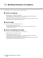
Multi-feed Detection
Multi-feed is an error that occurs when two or more sheets are fed simultaneously. You can set
conditions so that the scanner will stop its operation and display an error message when Multifeed is detected.
Multi-feed can be detected based on the “Paper Overlapping” or “Paper Length”.
Skew
With this option, you can set the scanner so that it will stop its operation and display error
messages when any skewed document is detected.
Do not stop scanning upon detection
With this option, you can set the scanner so that it continues scanning even if any Multi-feed or
skew is detected.
Multifeed Recovery
Scaning is not restarted for the set period (minutes) of time after a multifeed error. This period is
specified here. If scanning is not started after the set minutes, the application is notified of the
error by the driver. If Auto-cancel timer is set to 0, the application will never be notified of the
error.
2.13 Configuring the Scan Settings
53
[Gamma] tab
Pattern
Specifies how to correct Gamma. You can select a pattern from [Default], [Normal], [Soft],
[Sharp], [Custom] and [Bright].
Note that [Custom] and [Bright] are only available when “Color” is specified.
Camera
Specifies side(s) to which you want to apply the settings made on this window.
Custom Properties
Can be specified when [Custom] or [Bright] is selected in the [Pattern] list.
You can specify the numeric values of [Gamma], [Brightness], [Contrast], [Shadow] and
[Highlight]. If these values are changed while [Bright] is selected, the pattern switches to
[Custom].
54
2.13 Configuring the Scan Settings
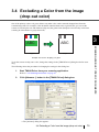
[Color Dropout] tab
Red, Green, Blue (Light’s three primary colors) or any color can be selected to drop out from the documents to be scanned. For example, if you specify “Red” when scanning black letters with red outlines, only
the black part of the letters are scanned.
You can use this function when black and white or gray scale is selected.
2
BASIC SCANNER OPERATIONS
Enable Color Dropout
Color Dropout is enabled.
Dropout Red
An image in which red color dropout has occurred is output.
Dropout Green
An image in which green color dropout has occurred is output.
Dropout Blue
An image in which blue color dropout has occurred is output.
Use Custom Color
Dropout
An image in which a selected color dropout has occurred is output.
Custom Color Dropout
Any color to drop out can be specified when “Use Custom Color Dropout” is selected.
2.13 Configuring the Scan Settings
55
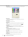
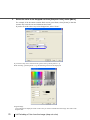
[Edit...] button
Displays the [Select Dropout color] dialog box where you can view a sample image and
select up to three colors.
Original Image
The sample color is shown. By clicking colors in Original Image, you can select the
color to drop out from the image.
Dropout Image
The image after color dropout is shown.
Dropout Color
Both the numeric values and the sample color of the specified color to drop out are
shown.
You can change the numeric values by directly inputting them or using
.
Priority Black
Mark this checkbox when you want no color dropout for scanning letters.
Marking this checkbox avoids dropout of colors with low saturation such as black,
which is often used for letters.
Sensitivity
You can specify the degree of color dropout.
The range of sensitivity: 15 - 180 degree (30 degree by default)
The larger the degree, the broader the range of colors to drop out.
[File...] button
You can select an image file (*.bmp format) to display it in “Original Image”.
[Apply] button
Changes made are applied and the “Select Dropout color” window is closed.
[Cancel] button
Changes are voided and the “Select Dropout color” window is closed.
56
2.13 Configuring the Scan Settings
[Compression] tab
You can configure compression settings for scanning images in color or gray scale on this tab.
2
BASIC SCANNER OPERATIONS
JPEG Quality:
Specify the compression level and image quality.
Sample Ratio:
Specify the sample ratio by which images are compressed. The file size of images
compressed by the ratio of YUV4:2:2 is smaller than that of images compressed by the
ratio of YUV4:4:4.
[About] tab
You can check the version number of the ISIS driver as well as hardware information of the scanner connected to the personal computer.
2.13 Configuring the Scan Settings
57
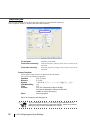
[Imprinter] tab
You can make settings for Pre-/Post-Imprinter Options (to be purchased separately).
Unless Imprinter Option is installed, this tab will be unshown.
Do not print
Imprinter is not used.
Print before scanning
With Pre-Imprinter, printing is done on the front face of the
document.
Print after scanning
With Post-Imprinter, printing is done on the rear face of the
document.
Format Template:
Letters typed in this text box are printed on the document.
You can use the following characters.
Alphabet
A to Z, a to z
Numeric
0, 1 to 9
Symbol
!“$#%&‘()*+,-./:;<=>?@[\]^_‘{|}~
Year/Month/Day
%Y
Time
%T
Counter
%S (You can select 3-digit to 8-digit.
You can be placed the counter at the first,
middle or end of the string.)
Other
One byte space
Up to 43 characters can be typed in.
ATTENTION
58
To print characters "#" and "%", you have to type letters ## and %%
respectively because these are special characters. Please be reminded
that typing only one letter (#) displays the counter.
2.13 Configuring the Scan Settings
Date
Specifies how to display the date.
Format:
Delimiter:
You can specify how to display the date.
You can select delimiters (grouping separators).
Counter
2
Specifies the rule of display.
Initial Value:
Field Width:
BASIC SCANNER OPERATIONS
You can specify the initial vale.
You can specify the number of digits for the counter.
(3 to 8 digits).
Number Control: You can specify the number by which the counter is
incriminated/decremented.
Top Margin:
Specifies the location where the printed string of characters starts.
Setting range:
Minimum unit:
0.5 to 10.5 in.(1.27 to 26.7cm)
0.1 in.(0.01cm)
Units:
Selects a unit for Top Margin values i(nch, cm, or pixel).
Font:
Selects the font to use for printing (Normal, Bold, or Narrow).
Rotation:
Specifies the orientation of strings of characters.
2.13 Configuring the Scan Settings
59
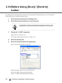
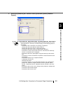
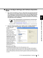
2.14 Before Using [Scan] / [Send to]
button
By setting the link of the application software to the [Scan] button and [Send to] button, you can launch the
linked application by simply pushing the button.
1.
Select [Control panel] from the [Start] menu.
2.
Select [Property] from [Scanner and Cameras].
HINT
3.
For Windows XP, when the control panel is displayed in “Category” mode,
select [Printer and other hardware] and then click [Scanner and camera].
Display the “fi-5950” properties.
Right-click the "fi-5950d" icon.
For Windows 2000, double-click the “fi-5950d” icon.
4.
Select the [Event] tab.
5.
Select the event to launch the application.
Select event from the [Select event] menu.
With this function, the next events can be selected.
Scan button (When clicking on [Scan] button)
Send to 1-9 (When clicking the [Send to] button)
60
2.14 Before Using [Scan] / [Send to] button
6.
Select the application executed by the event.
For Windows XP, Windows Server 2003 and Windows Vista, select [Performing selected
program] under [Performing] and then select the application to be processed.
7.
Click OK.
2
BASIC SCANNER OPERATIONS
2.14 Before Using [Scan] / [Send to] button
61
2.15 Resuming from Power Saving Mode
Power saving mode saves the power consumption of the scanner while the power is turned on. When the
scanner is left without operation for 15 minutes or more (factory initial setting), it automatically enters the
power saving mode.
When the scanner entered the power saving state, the LCD indication of Operation panel becomes off and
the green LED lamps for Power button and Paper Thickness keeps lighting.
If you want to resume the scanner from the power saving mode, take any of these actions below.
•Set documents on the hopper.
•Press any button on the Operator panel (except the Power button*).
* If you press the power button for two seconds or longer, the power is turned off.
•Execute any command from the scanner driver screen in the PC.
Also, the scanner can be set to turn itself off automatically when it is turned on and left unused for a certain
period of time.
You can save the power consumption by having the scanner turn off automatically.
To enable this setting, select the [Power off after a certain period of time] check box in [Device Setting] of
the Software Operation Panel. For details, refer to “8.2 Power saving setting” on page 190.
To turn the scanner back on when it is automatically turned off, press the power button on the scanner.
For details, refer to “2.1 Turning the Scanner ON /OFF” on page 8.
ATTENTION
HINT
62
• Depending on the application you are using, the scanner may not be
turned off automatically even when the [Power off after a certain period
of time] check box is selected.
• If the scanner turns itself off automatically while you are using an image
scanning application, close the application first, then turn the scanner
back on.
The waiting time for entering the power saving mode can be set in a range
from 15 to 55 minutes in steps of 5 minutes. To set the power saving mode,
refer to “8.2 Power saving setting” on page 190.
2.15 Resuming from Power Saving Mode
2.16 Image Scanning Application
This section explains about the bundled “ScandAll PRO” image scanning application, which is used as an
example to explain the procedures in this manual.
ScandAll PRO supports both TWAIN and ISIS drivers. By defining scan settings as profiles, you can customize the settings according to your preference.
2
BASIC SCANNER OPERATIONS
2.16 Image Scanning Application
63
2.17 Centralized Management of
Scanners
This section explains about managing a large number of scanners in a unified manner by providing the following capabilities.
• Simultaneously update settings for multiple scanners and their drivers.
Because there is no need to update each scanner one by one, a significant
reduction is achieved in the time required to update a large number of scanners.
• Monitor scanners to check for any consumable parts that require replacement, or
the occurrence of errors.
The alerts for consumable part replacement and errors are provided by scanners,
which provides an easy way of checking the operating status of scanners.
To enable the above functions, "Scanner Central Admin" is required which consists of four applications
bundled with this product:
• Scanner Central Admin Server
Install this application in the main computer that is used for the centralized management of
scanners.
By registering scanners on the Scanner Central Admin Server, you can build a system to run a
unified management for all scanners.
• Scanner Central Admin Console
Install this application in a computer to upload update modules and to monitor the operating status
of the scanners.
The administrators can perform these tasks from the Scanner Central Admin Console window,
where they can also check the alerts for consumable replacement and errors sent from the scanners.
• Scanner Central Admin Agent
Install this application in a computer connected to a scanner. It allows scanners to link with the
Scanner Central Admin Server.
Linking with the Scanner Central Admin Server will enable you to apply updates on scanner
settings, and the scanner can also send alerts on consumable replacement and errors.
• SCAModule Creator
Use this application to create update modules to upload onto the Scanner Central Admin Server.
It is only required for creating update modules.
64
2.17 Centralized Management of Scanners
Scanner Central
Admin Server
Scanner Central
Admin Console
Upload update modules/
check update status
Alerts for consumable part
replacement and errors
SCAModule
Creator
Administrator
2
Scanner
Scanner Central
Admin Agent
Scanner
Scanner
Scanner Central
Admin Agent
Scanner Central
Admin Agent
BASIC SCANNER OPERATIONS
Update
module
Scanner
Scanner Central
Admin Agent
:
:
Update
Alerts for consumable part
replacement and errors
For more details, refer to the Scanner Central Admin User’s Guide.
2.17 Centralized Management of Scanners
65
66
2.17 Centralized Management of Scanners
3
SCANNING VARIOUS
TYPES OF DOCUMENTS
This chapter describes how to scan various types of documents.
This chapter explains operations using the screens of Windows XP.
Depending on your OS, your PC's screen shots and the operation may be
different from this manual. Be aware that when the TWAIN driver or the
ISIS driver is updated, the screens and operations noted in this chapter may
change. In that case, refer to the User's Guide provided with the update.
For information on how to scan documents in the following methods, refer to
"ScandAll PRO User’s Guide".
• Saving Scanned Image in PDF File Format
• Dividing a Multipage Document Using Patch Codes
• Dividing a Multipage Document Using Barcodes
• Specifying the Result of Zone OCR as a File Name
• Specifying the Result of Barcode Recognition as a File Name
• Creating Saving Folders for Each Batch Scan
• Saving Scanned Images from a Batch Scan to Microsoft
SharePoint Server
• Restarting a Suspended Batch Scan
• Outputting Indexing Information File and Linking with an
Application
3.1 Double Sided Scanning .......................................................69
3.2 Scanning Documents Longer than A3 ...............................70
3.3 Scanning Documents with different widths .......................72
3.4 Excluding a Color from the image (drop out color) ..........75
3.5 Skipping blank Pages ..........................................................78
3.6 Scanning the Image Brighter...............................................81
3.7 Detecting Multifeeds ............................................................84
67
3.8 Correcting skewed Documents .......................................... 86
3.9 Setting Auto Correction for Document Page
Orientations .......................................................... 88
3.10 Multi Image Output............................................................. 91
3.11 Color/monochrome Auto Detection.................................. 94
3.12 Not detecting Multifeed for fixed format .......................... 97
68
3.1 Double Sided Scanning
When you want both sides of a document to be scanned at the same time, set the feeding option to
“Duplex”.
Below is the procedure with TWAIN driver.
1.
Set the document on the hopper.
Refer to section “2.6 Loading Documents on the Hopper” on page 17.
2.
3
Adjust stacker in accordance with document size.
Refer to section “2.7 Setting up the Stacker” on page 22.
SCANNING VARIOUS TYPES OF DOCUMENTS
3.
Start TWAIN driver with the application used.
Refer to section “2.10 Scanning Documents” on page 30.
4.
Set the [Scan Type:] to “ADF (Duplex)”.
5.
Set resolution and document size and so on, and then click [Scan] button.
3.1 Double Sided Scanning
69
3.2 Scanning Documents Longer than
A3
When scanning documents longer than A3, set the feeding option to “Long Page”.
This scanner can scan documents up to 3,048mm (120inch) long.
Below is the procedure with TWAIN driver.
1.
Set the document on the hopper.
Refer to section “2.6 Loading Documents on the Hopper” on page 17.
2.
Adjust stacker in accordance with document size.
Refer to section “2.7 Setting up the Stacker” on page 22.
HINT
When scanning long pages (longer than A3), the document may be longer
than the stacker extension even if it’s pulled to the outermost position. In
case like this, place a thick paper about the size of A4 on the stopper and
make a slope as depicted below.
Thick Paper
Stopper
Stacker Extension
3.
Start TWAIN driver with the application used.
Refer to section “2.10 Scanning Documents” on page 30.
70
3.2 Scanning Documents Longer than A3
4.
Set [Scan Type:] to “Long Page (Front Side)” or “Long Page (Duplex)”.
Choose “Long Page (Front Side)” when scanning one side; “Long Page (Duplex)”, both sides.
3
SCANNING VARIOUS TYPES OF DOCUMENTS
⇒ The “Set the document size” screen will appear.
5.
Click [OK] after setting the document
When excessively long length is specified, the scanning speed may be slow. So, it is
recommended to specify the closest length to the actual document.
6.
Set resolution and document size and so on, and then click [Scan] button.
3.2 Scanning Documents Longer than A3
71
3.3 Scanning Documents with different
widths
When you scan a batch of documents with different widths, follow the instruction below.
1.
Align the leading edge of the documents.
Aligning the document
alongside their center line
Aligning the document
with its left (or right) edge
This section describes the procedure to align the document alongside their center line.
For the procedure to align the document with its left (or right) edge, refer to “ (2)Setting the
document by either Side Guide of the hopper.” on page 19.
2.
Load the documents on the center of the hopper.
Pick roller
72
3.3 Scanning Documents with different widths
Load the documents so that each sheet can be reached by the pick roller.
(If the documents are not placed below the Pick roller, the document feeding will not be possible.)
ATTENTION
3
SCANNING VARIOUS TYPES OF DOCUMENTS
Pick roller
3.
Align the side guides to the width of the widest document.
原稿
4.
幅
大
く異
場合
原稿の幅がほぼ同じ場合
Align the stacker’s position.
Refer to “2.7 Setting up the Stacker” on page 22 for details.
3.3 Scanning Documents with different widths
73
5.
Start up the scanner driver.
Refer to “2.10 Scanning Documents” on page 30 for further information about how to start up
the scanner driver.
6.
Perform the settings for the scanning on the scanner driver’s
configuration window.
For the TWAIN driver
Paper size: (Main display)
Set the width of the widest, and the length of the longest document.
Automatic size and skew detection: ([Option] Screen [Rotation] tab)
Select Automatic Page Size Detection.
For the ISIS driver
Cropping: (on the [Main] tab)
Select [Automatic].
7.
Scan
⇒ The images of each document will be generated according to their size and displayed on
the screen.
Originals
ATTENTION
74
Images
• When scanning mixed size document, because the hopper side guides
will not function, the scanned images are easily skewed.
We recommend you to enable “Automatic Page Size Detection”.
• Multifeed Detection by length cannot be used together with “Automatic
Page Size Detection”.
• Refer to "7.8 Scanning Mixed Documents" on page 170 for details on
scannable mixed size documents.
3.3 Scanning Documents with different widths
3.4 Excluding a Color from the image
(drop out color)
One of the primary colors: red, green ,blue or any other color can be removed (dropped out) from the
scanned image data. For example, if the document contains black text in a green frame, you can set the
scanner to read only the text and eliminate (drop out) the green frame.(Dropout color will only work when
scanning in monochrome or grayscale mode).
ABC
3
ABC
Output
Example: the result of “dropping out” green.
To set the scanner to drop out a color, change the settings in the [TWAIN Driver] dialog box before scanning.
The following shows the procedure for changing the settings in this dialog box.
1.
Start TWAIN Driver from your scanning application.
Refer to “2.10 Scanning Documents” on page 30.
2.
Click [Advance...] button in the [TWAIN Driver] dialog box.
⇒ The [Advance] dialog box appears.
3.4 Excluding a Color from the image (drop out color)
75
SCANNING VARIOUS TYPES OF DOCUMENTS
Original
3.
Select the color to be dropped out from [Dropout Color] under [More].
For example, if the document contains black text in green frame, select [Green] so that the
scanner only reads the text and eliminates the frames.
If you do not wish to have any colors dropped out, select “None”.
If you wish to drop out a customed color, please select [custom pattern 1-3].
When selecting [custom pattern 1-3], the following screen will be displayed.
Original Image
Color samples are displayed. Click on the color you wish to exclude from the image. This will set the
dropout color.
76
3.4 Excluding a Color from the image (drop out color)
Dropout Image
The image as it will be generated after the dropout is displayed.
Dropout color
The selected dropout color will be shown as numeric value and as color sample.
You can enter a numeric value directly or use the [ ▲ ]/[ ▼ ] buttons to change the dropout color.
Priority Black
If you do not wish to drop out text from the image, please mark “Priority Black”.
Colors of low saturation (like black), that are used normally for texts will not be dropped out by this
function.
3
Sensitivity:
The sensitivity for the detection of the selected color to be dropped can be adjusted.
SCANNING VARIOUS TYPES OF DOCUMENTS
Setting range: 15 - 180 degree (default setting: 15 degrees)
The bigger the value for the sensitivity is set, the color range (tones) of the selected dropout color becomes
wider (i. e. the tolerance for the color detection gets bigger).
[File...] button
An arbitrary image file (*.bmp format) can be displayed in [Original Image].
[Apply] button
The settings made in this screen will be applied and the window is closed.
[Cancel] button
The settings made in this screen will be aborted and the window is closed.
4.
Click [OK] button.
[TWAIN Driver] dialog box will be redisplayed.
Then, scan the documents using this dialog box.
3.4 Excluding a Color from the image (drop out color)
77
3.5 Skipping blank Pages
If enabled, the scanner will automatically detect blank pages of the documents and remove them from the
scanned image. For example, when double sided and single sided pages are scanned together, the blank
side of the single sided pages will be skipped during scanning. Change settings in the [TWAIN Driver] dialog box to enable skipping blank pages at scanning documents.
1.
Start TWAIN Driver from your scanning application.
Refer to “2.10 Scanning Documents” on page 30.
2.
Click the [Option...] button in the [TWAIN Driver] dialog box.
⇒ The [Option] dialog box appears.
3.
78
Click the [Job/Cache] tab.
3.5 Skipping blank Pages
4.
Check the [Blank Page Skip] box.
3
SCANNING VARIOUS TYPES OF DOCUMENTS
When the check box is marked, “Cache Mode” will change to “Use both memory”.
5.
Using the slider control under [Blank Page Skip], specify the Blank Page
Skip degree.
<In Binary/Halftone mode>
For white pages, use the [Black Dots Ratio] slider bar to set the skip condition. For black pages,
use the [White Dots Ratio] scroll bar to set the skip condition.
The value displayed to the right of the scroll bar displays the noise ratio(*1). If a scanned
document is below this value, it is recognized as a blank page. The range is OFF(- -) and from
0.2% to 3.0% (in increments of 0.2%).
*1: Ratio of black dots included in the scanning area. (for white pages)
<In Color/Grayscale mode>
The [TWAIN Driver] dialog box will be redisplayed. Then, perform the scanning operation on
the dialog box.
Use the slider bar to set the skip condition in five stages from 1 to 5. The bigger the value, the
more likely a page will be detected as blank.
3.5 Skipping blank Pages
79
6.
Click [OK] when done.
The [TWAIN Driver] dialog box will return. continue from there.
80
3.5 Skipping blank Pages
3.6 Scanning the Image Brighter
The brightness of the scanned image can be increased for scanning in grayscale or color.
The following shows the procedure for changing the settings in this dialog box.
1.
Start TWAIN Driver from your scanning application.
Refer to “2.10 Scanning Documents” on page 30.
2.
3
Select grayscale or color in [Image Mode].
SCANNING VARIOUS TYPES OF DOCUMENTS
3.6 Scanning the Image Brighter
81
3.
Click [Advance...] button in the [TWAIN Driver] dialog box.
⇒The [Advance] dialog box appears.
4.
Click the [Color] tab, and then select [Bright] in [Preset Gamma].
5.
Click [OK] button.
[TWAIN Driver] dialog box will be redisplayed. Then, scan the documents using this dialog
box.
82
3.6 Scanning the Image Brighter
HINT
When using applications other than ScandAll PRO, you can also increase the default
brightness of the TWAIN driver. Select [Tools] - [FtSwtGmm] - [Twain] in the Setup
DVD-ROM and double-click "FtSwtGmm.exe", and then select [Bright) in the [Default
scan setting (TWAIN)] dialog box.
3
SCANNING VARIOUS TYPES OF DOCUMENTS
3.6 Scanning the Image Brighter
83
3.7 Detecting Multifeeds
“Multifeed” is an error that occurs when two or more sheets are accidentally fed into the ADF at the same
time. You can set the scanner to display an error message or ring the buzzer when the scanner detects a
multifeed.
Multifeed Detection can be set either through the scanner driver dialog box or through “Software Operation Panel”. Refer to “8.4 Multifeed Detection” on page 193 for details on set up multifeed detection
through “Software Operation Panel”.
The following shows the procedure for changing the settings in the [TWAIN Driver] dialog box.
1.
Start TWAIN Driver from your scanning application.
Refer to “2.10 Scanning Documents” on page 30.
2.
Click the [Option...] button in the [TWAIN Driver] dialog box.
⇒ The [Option] dialog box appears.
3.
84
Click the [Job/Cache] tab.
3.7 Detecting Multifeeds
4.
Select the detection conditions from [Multifeed Detection] under [ADF
Option].
3
None
Check overlapping
Check length
Check overlapping
and length
Hardware settings
Multifeed detection is not performed.
The scanner monitors for the overlapping of documents. The scanner detects a
multifeed by differences in ultrasonic propagation. When this method is
slected, two more options are available specified by other sections.
• Multifeed detection areas can be narrowed separately for left/middle/right
Ultrasonic sensors to avoid unintensional multifeed detection of sticked photogragh or something on the document. To specify this, go to Step 4 in Section “8.4 Multifeed Detection” on page 193.
• If photogragh or something is sticked on the document and its size and/or
position are same, you can easily let the scanner memorize its size and/or
position just scanning those document. To use this function, go to Section
“8.10 Intelligent Multifeed Function” on page 205 or Section “3.12 Not
detecting Multifeed for fixed format” on page 97.
The scanner monitors the length of documents. It detects a multifeed by differences in the document length when two or more document sheets are fed overlapping.
The scanner monitors both document overlapping and length to detect
multifeeds.
The scanner will detect multifeeds according the settings configured on the
Software Operator Panel. Refer to “8.4 Multifeed Detection” on page 193.
Furthermore, refer to "7.5 Multifeed Detection Conditions" on page 166 for detailed
information about the document for multifeed detection.
5.
Click the [OK] button.
The display returns to the [TWAIN Driver] dialog box. Then, perform the scanning operation
on the dialog box.
The scanner will stop scanning if a multifeed is detected. When this happens, press the [Send
to] button on the Operator panel to eject the multifeed document.
3.7 Detecting Multifeeds
85
SCANNING VARIOUS TYPES OF DOCUMENTS
You can choose the following:
3.8 Correcting skewed Documents
You can set the scanner to automatically detect and correct skewed documents that are fed into the ADF.
The configuration is done through the scanner driver.
The following shows the procedure for changing the setting from the [TWAIN Driver] dialog box.
1.
Start TWAIN Driver from your scanning application.
Refer to “2.10 Scanning Documents” on page 30.
2.
Click the [Option...] button in the [TWAIN Driver] dialog box.
⇒ The dialog box appears.
3.
86
Click the [Rotation] tab.
3.8 Correcting skewed Documents
4.
Select the [Automatic Page Size Detection] from the [Automatic Size and
Skew Detection] menu.
3
SCANNING VARIOUS TYPES OF DOCUMENTS
5.
Click the [OK] button.
The display returns to the scanning operation [TWAIN Driver] dialog box.
ATTENTION
When using either of the following documents, the Automatic page size
detection may not function correctly.
1. Paper of weight 52g/m2 or less.
2. Non-rectangular documents.
3. Documents with the margin filled with dark colors.
HINT
Depending on the condition of the document, a black frame appears around
the perimeter of a page. If you find it obtrusive, you can remove the edge by
using the "Page Edge Filler" function. For information about this function,
refer to “8.9 Page Edge Filler (Automatic Page Size Detection)” on page 203.
3.8 Correcting skewed Documents
87
3.9 Setting Auto Correction for
Document Page Orientations
You can direct the scanner to automatically correct a batch of documents with a mixture of page orientations.
Opqrstu
DEF
Vwxyz.
Abcdefg
Hijklmn
DEF
Abcdefg
Hijklmn
Opqrstu
Vwxyz.
Originals
Output images
The following shows the procedure for changing the setting from the [TWAIN Driver] dialog box.
1.
Start TWAIN Driver from your scanning application.
Refer to “2.10 Scanning Documents” on page 30.
2.
Click the [Option...] button in the [TWAIN Driver] dialog box.
⇒ The dialog box appears.
88
3.9 Setting Auto Correction for Document Page Orientations
3.
Select the [Rotation] tab, and then select [Automatic] under [Rotation
Degree].
3
SCANNING VARIOUS TYPES OF DOCUMENTS
ATTENTION
•This function determines a document page orientation based on the characters printed on it. So it may not work properly for the following kinds of
documents:
− Documents with a resolution for scanning not between:
300 dpi and 600 dpi (in Black & White mode) or
200 dpi and 600 dpi (in Color or Grayscale mode)
− Documents with many extremely-large/small characters
− Documents on which the pitches of lines or characters are extremely
narrow, or characters are overlapped
− Documents with many photographs or figures and only a few characters
− Documents on which characters are printed in various directions such
as drawings
− Documents written only in capital characters
− Handwritten documents
− Skewed documents
− Documents written in a non-supported language. The supported languages are: Japanese, English, German, French, Spanish, Italian,
Korean, Traditional Chinese, Simplified Chinese, Russian, and Portuguese
− Documents with uneven colors, design and/or patterns in background
− Documents with intricate design
− Documents with a lot of noise
3.9 Setting Auto Correction for Document Page Orientations
89
•To judge text in documents, use a language that is set in Windows’s
Regional and Language Options.
•The image orientation may not be corrected properly depending on the
scanner driver setting at scanning (e.g. dithering).
•If you cannot correct the image orientation properly, use the Edge Emphasis function of the drivers to correct it.
•Shadows may remain on the edge of the scanned image.
•[Automatic] in [Rotation Degree] is available only when ScandAll PRO is
installed.
4.
Click the [OK] button.
The display returns to the scanning operation [TWAIN Driver] dialog box
90
3.9 Setting Auto Correction for Document Page Orientations
3.10 Multi Image Output
It is possible to get an output both in Color/Grey scale and binary black and white.
This function may not work properly depending on the application software you use.
ABC
ABC
SCANNING VARIOUS TYPES OF DOCUMENTS
Original
3
Output
Example:Color document scanned with Multi Image.
The Multi Image setting can be done on the Scanner Driver.
The following operation uses the TWAIN driver.
1.
Start TWAIN Driver from your scanning application.
Refer to “2.10 Scanning Documents” on page 30.
2.
Please check the [Enable Multi Image] checkbox in the [TWAIN Driver] window.
* When [Long Page..] is specified at [Scan Type:], you can not check this checkbox.
Main screen
3.10 Multi Image Output
91
⇒ The [Multi image output] dialog box will be displayed.
3.
Select [Multi image output] under “Output mode”.
4.
Set the order of the output in “Order (for Multi image output)”.
Primary: Color/Grayscale Secondary: Binary
The output order will be: [Color or Grey scale images] [Binary monochrome images]
Primary: Binary Secundary: Color/Grayscale
The output order will be: [Binary monochrome images] [Color or Grey scale images]
92
3.10 Multi Image Output
5.
Select under “Select Current face” the side of your choice and perform then for
each scan settings on the main configuration screen.
6.
Click the [Scan] button to scan the document.
3
SCANNING VARIOUS TYPES OF DOCUMENTS
3.10 Multi Image Output
93
3.11 Color/monochrome Auto Detection
The scanner detects whether the scanned document is color or binary monochrome. According to this detection, the
images will be output in color (or grey scale) for colored documents, ide binary black and white for monochrome
documents.
*Depending on the application, this function may not operate properly.
The settings for Multi Image can be done on the Scanner Driver.
The following operation uses the TWAIN driver.
1.
Start up TWAIN driver from the application you are using
Refer to “2.10 Scanning Documents” on page 30.
2.
Please check the [Enable Multi Image] checkbox in the [TWAIN Driver] window.
* When [Long Page..] is specified at [Scan Type:], you can not check this checkbox.
Main screen
94
3.11 Color/monochrome Auto Detection
⇒ The [Multi Image output] dialog box will be displayed.
3
Under [Output Mode Selection], check [Color/Monochrome Auto Detection].
4.
Select under [Current Side Selection] the side of your choice and perform then for
each scan settings on the main configuration screen.
SCANNING VARIOUS TYPES OF DOCUMENTS
3.
The scan settings are done in advance, for the case documents are detected as [Color/Grey scale] or
[Monochroe (binary black and white)].
3.11 Color/monochrome Auto Detection
95
5.
96
Click the [Scan] button to scan the document.
3.11 Color/monochrome Auto Detection
3.12 Not detecting Multifeed for fixed
format
When sheets with glued photographs or sticky notes are scanned, the scanner can accidentally detect a
multifeed error, and scanning is interrupted. This section explains "Intelligent Multifeed Function", or a
resolution function that eliminates such a problem (hereinafter referred to as "this function").
This function has one manual mode and two automatic modes as follows:
•Manual mode in which multifeed error detection is disabled by manipulating the Operator
Panel
•Automatic mode in which the scanner ignores multifeed errors based on information about
the glued photos and labels. The above information is stored in memory; it refers to the
position and length of those slips (hereinafter referred to as the "glued paper").
SCANNING VARIOUS TYPES OF DOCUMENTS
Sticky note
Glued photos or labels
3.12 Not detecting Multifeed for fixed format
3
97
■ Intelligent Multifeed Function
There are three modes; select one according to your needs.
Select a mode by using the Software Operation Panel. For how to select a mode, see section 2.
Item in
Software
Operation
Panel
Method to bypass Multifeed
Applicable case
Comments
Manual mode
(Bypass by front
panel button)
When a Multifeed error occurs, press [Send to] to
eject sheet in the scanner's transport path. Examine
the last sheet scanned.
If no paper is glued on the ejected sheet, return the
sheet to the Hopper and press the [Scan] button.
If glued paper is present on the ejected sheet, return
the sheet to the Hopper, press the [Function] button
once (Slow Blink rate of the function number display
will change to Fast Blink rate) and press the [Scan]
button. The scanner will not check for a Multifeed
error on the first sheet being scanned.
The following sheets are checked for Multifeed
errors with the already-existing Multifeed settings in
the Software Operation Panel or driver. (Default)
Use this mode when you
want to continue scanning, while checking for
glued paper every time a
multifeed error is
detected.
Pages scanned before
errors are sent to memory.
Extraneous images may
be generated during a
Multifeed error.
Automode 1
(Bypass by combination of length
and position)
When a Multifeed error occurs, press [Send to] to
eject sheet in the scanner's transport path. Examine
the last sheet scanned.
If no paper is glued on the ejected sheet, return the
sheet to the Hopper and press the [Scan] button.
If glued paper is present on the ejected sheet, return
the sheet to the Hopper, press the [Function] button
once (Slow Blink rate of the function number display
will change to Fast Blink rate) and press the [Scan]
button. The scanner will record the length and position of the glued paper that caused the error.
The following sheets are checked for Multifeed
errors and then the scanner bypasses Multifeed, if
the scanned overlap pattern is same as already
recorded pattern(s).
Use this mode when you
scan many sheets in a
fixed format; for example, when every sheet has
the same size glued paper
at the same position.
Pages scanned before
errors are sent to memory.
Extraneous images may
be generated during a
Multifeed error.
Automode 2
(Bypass by
length)
When a Multifeed error occurs, press [Send to] to
eject paper in the scanner's transport path. Examine
the last sheet scanned.
If no paper is glued on the ejected sheet, return the
sheet to the Hopper and press the [Scan] button.
If glued paper is present on the ejected sheet, return
the sheet to the Hopper, press the [Function] button
once (Slow Blink rate of the function number display
will change to Fast Blink rate) and press the [Scan]
button. The scanner will record the length of the
glued paper that caused the error.
The following sheets are checked for Multifeed
errors and then the scanner bypasses Multifeed, if
the scanned overlap pattern is the same or shorter
than the already recorded pattern.
Use this mode when you
scan multiple sheets,
each having differentsize glued paper at a different position.
Pages scanned before
errors are sent to memory.
Extraneous images may
be generated during a
Multifeed error.
98
3.12 Not detecting Multifeed for fixed format
■ How to Configure Settings with Software Operation
Panel
1.
First, make sure that the scanner is connected to the personal computer,
and then turn on the scanner. Second, press the [Function] button until
"C" is displayed on the Operator Panel. Third, press the [Send to] button.
Finally, the Software Operation Panel window will appear. (When Kofax
VRS (optional) is used, display the Software Operation Panel window by
using the Start menu in Windows.)
2.
If the [Software Operation Panel] is password protected, enter the password to cancel the View Only mode.
For details on how to enter the password to cancel the View Only mode,
refer to “Password Setting” on page 177.
SCANNING VARIOUS TYPES OF DOCUMENTS
ATTENTION
3
Select the "Device setting 2" tab, and then select "Intelligent Multifeed
Function" under "Device Setting". Using this tab, do the following:
•Intelligent Multifeed
Function
Select one of three modes
described above.
•Clear overlap pattern
When this checkbox is
selected, the overlap
pattern (length and position)
remembered by Auto mode
is deleted from memory.
If [Do not remember] is
specified for [Remember
multifeed pattern at poweroff], the overlap pattern is
automatically deleted upon
changing the mode.
However, changing the
mode does not delete the
overlap pattern if
[Remember] is specified.
•Enable Scan button (VRS)
This setting is only enabled when Kofax VRS (optional) is used.
You can specify whether you want to use the [Scan] button to restart scanning after a
multifeed error when Kofax VRS (optional) is used. Select [Enable] to use the [Scan]
button. (When [Disable] is selected, scanning is restarted using the Autoresolve function
of Kofax VRS (optional).) Note that this button is grayed out when Kofax VRS (optional) is
not used.
3.12 Not detecting Multifeed for fixed format
99
•Remember multifeed pattern at power-off
Specify whether or not to remember the multifeed pattern upon turning off the power.
When [Remember] is specified, the multifeed pattern used before the power-off remains
available after turning the power back on (Up to 8 patterns can be stored in memory).
100
3.12 Not detecting Multifeed for fixed format
■ Before Using This Function
Configure the following settings before using this function:
When the TWAIN driver is used, select [Use Memory on Scanner] or [Use
both Memory] as [Cache Mode] on the [Job/Cache] tab of the "Option"
dialog box. Otherwise you can not continue scanning after a multifeed
error.
2.
When ISIS or the TWAIN driver is used, if you want to start scanning by
using the [Scan] button after a multifeed error, configure the driver
settings as described below.
[TWAIN driver] Mark the [Enable Scanner Panel] and "Enable [Scan] Button" checkboxes on the [Startup]
tab of the "Option" dialog box.
3.12 Not detecting Multifeed for fixed format
101
3
SCANNING VARIOUS TYPES OF DOCUMENTS
1.
[ISIS driver] Mark the "On" checkbox under "Multifeed Recovery" and set "Auto-cancel Timer" to 0 or
any value (minutes) on the [Paper Handling] tab of "Properties for Fujitsu fi-5950..." dialog
box.
Auto-cancel Timer:
Scanning is not restarted for the set period of time (minutes) after a multifeed
error. If scanning is not started after the set minutes, the application is notified
of the error by the driver. Note that if the Auto-cancel Timer is set to 0, the
application will never be notified of the error.
3.
102
In the Software Operation Panel or driver dialog box, select [Check
Overlapping] or [Check Overlapping and length difference].
3.12 Not detecting Multifeed for fixed format
■ Descriptions
1.
After a multifeed error, press the [Send to] button to eject sheets from the
transport path, or open the cover and remove sheets from the transport
path. Return the ejected or removed sheets onto the hopper. When the
sheets are removed, the function number displayed changes as follows:
Multifeed error
No sheets in the transport path
"U" and "2" is indicated alternately
A function number blinks
2.
[When using this function] Press the
[Function] button, and then make sure that
the function number blinks at shorter
intervals before you press the [Scan] button
or restart scanning by using the personal
computer.
From then on, the blinking speed of the
function number is increased or decreased
(switches between "fast" and "slow") every
time the [Function] button is pressed. When
sheets are scanned while the function
number blinks at shorter intervals, the
scanner operates according to the mode
selected as follows:
•Manual mode (Bypass by front panel button)
Function number
Function
Hopper Height
Paper Thickness
Thin
Thick
Send to
Scan
Operator panel
The first sheet is scanned without a multifeed error being detected. When the second and
later sheets are scanned, multifeed errors are detected based on the settings that have
been configured in the Software Operation Panel or driver dialog box.
•Auto mode1 (Bypass by combination of length and position)
The scanner remembers the length and location of glued paper (overlap pattern) that
caused a multifeed error and continues scanning. When glued paper of a similar pattern is
detected, the scanner automatically ignores it to avoid multifeed error detection. (Note
1)(Note 2)
•Auto mode2 (Bypass by length)
The scanner remembers the length of the glued paper that caused a multifeed error and
continues scanning. When glued paper of the same or shorter length is scanned, the
scanner automatically ignores it to avoid multifeed error detection. (Note 2)
3.12 Not detecting Multifeed for fixed format
103
SCANNING VARIOUS TYPES OF DOCUMENTS
If no paper is glued on a sheet but a multifeed error is
detected, press the [Scan] button or restart scanning by
using the personal computer (in this case, do not press the
[Function] button).
If glued paper is present on a removed/ejected sheet, and
you think it caused a multifeed error, go to step2.
3
104
Note 1:
In this mode, up to 32 overlap patterns can be remembered (stored in memory). When the 33rd
overlap pattern is detected, the first-remembered pattern is deleted from memory.
Note 2:
The remembered overlap patterns can be deleted from memory by pressing the [Function] button for 2 seconds or longer while the function number is blinking. After all overlap patterns are
deleted, the display indicates "o". By doing so, you can delete all 32 overlap patterns. Be careful not to delete necessary overlap patterns, too.
3.12 Not detecting Multifeed for fixed format
4
DAILY CARE
This chapter describes how to clean the scanner.
WARNING
• Take care not to pinch your fingers inside the
ADF.
• The glass inside the ADF becomes hot during
operation. Be careful not to get burned.
4.1 Cleaning Materials and Areas Requiring Cleaning .........106
4.2 Cleaning the Pad ................................................................108
4.3 Cleaning the Rollers (using the cleaning sheet) .............109
4.4 Cleaning the Rollers (with a lint-free cloth) ..................... 112
4.5 Cleaning the Transport path and the sensors ................. 116
105
4.1 Cleaning Materials and Areas
Requiring Cleaning
■ Cleaning materials
Cleaning materials
Part No.
Remarks
Cleaning sheet
CA99501-0016 (*1)
20 sheets/pack
Cleaner F1
PA03950-0352 (*1)(*2)
1 bottle, 100ml/bottle
Moisten cloth with this fluid
and wipe the scanner to clean.
Cotton swab
Commercially
available
Cleaning Wipe
PA03950-0419 (*1) (*3)
Lint-free dry cloth
Commercially
available (*4)
24 sheets/pack
*1)For the purchase of the cleaning material, contact the FUJITSU scanner dealer where you
purchased the scanner.
*2)It may take long before the cleaner vaporizes if a large quantity is used. When cleaning the
scanner parts, dampen a cloth with modest quantities of the cleaner. In addition, wipe off
the cleaner completely with a soft lint-free cloth to leave no residue on the surface of the
cleaned parts.
*3)Pre-moistened with Cleaner F1, Cleaning wipes are used instead of moistened cloths.
*4)Any lint-free cloth can be used.
106
4.1 Cleaning Materials and Areas Requiring Cleaning
■ Locations requiring Cleaning and Cleaning
Frequency
The following shows the standard cleaning frequency for each area requiring cleaning.
cleaning method
cleaning cycle
cleaning sheet
cloth moistened with
cleaner F1
every 10,000 scanned every 10,000 scanned
pages (*1)
pages (*1)
-
3
Pick rollers
3
3
Brake roller
3
3
Separator rollers
3
3
Feed roller
3
3
Pinch roller
3
3
Transport path
3
3
Glass
-
3
Skew-detection sensor
-
3
Document sensors
-
3
4
DAILY CARE
Pad
3 : Cleanable
- : Not cleanable
*1)During scanning, toner, paper dust, oil from carbonless paper, and glue stick to scanner
rollers. If the rollers are not cleaned regularly, these will become more difficult to remove.
Therefore, it is strongly recommended that the rollers be cleaned after daily use.
ATTENTION
• The scanner must be cleaned more frequently if you scan any of the following types of sheets:
• Documents of coated paper
• Documents that are almost completely covered with printed text
or graphics
• Paper whose back side has carbon.
• Chemically treated documents such as carbonless paper
• Documents containing a large amount of calcium carbonate
• Documents filled in with pencil
• Do not use aerosol sprays to clean the scanner. The air from the spray
may cause dirt and dust to enter the scanner mechanism and resulting
scanner failure or malfunction.
• You must clean the following area more thoroughly when you use fi590PRF or fi-590PRB imprinters. The imprinter ink tends to stick to the
document transport path.
• Removable sheet guide
• Glass sheet guide
• Feed rollers
• Pinch rollers
• You can confirm the number of scanned sheets after the last cleaning by
“5.2 How to check and reset the Consumable/Cleaning Counter” on
page 123.
4.1 Cleaning Materials and Areas Requiring Cleaning
107
4.2 Cleaning the Pad
1.
Open the ADF cover.
For details, refer to “2.3 Opening and Closing ADF” on page 12.
ADF cover
Pad
2.
Wipe the Pad (the parts of rubber) with a lint-free cloth, moistened with
cleaner F1, in the direction indicated by the arrows.
Pad
ATTENTION
3.
It may take long before the cleaner vaporizes if a large quantity is used.
When cleaning the scanner parts, dampen a cloth with modest quantities
of the cleaner. In addition, wipe off the cleaner completely with a soft lintfree cloth to leave no residue on the surface of the cleaned parts.
Close the ADF.
If all the cleaning is done, reset the Cleaning counter by referring “5.2 How to check and reset
the Consumable/Cleaning Counter” on page 123.
108
4.2 Cleaning the Pad
4.3 Cleaning the Rollers (using the
cleaning sheet)
Use the cleaning sheet to clean the upper and lower ADF transport path and the rollers.
1.
Open the Pre-Imprinter Cover when the power is off.
Pre-Imprinter Cover
4
DAILY CARE
Scan
2.
While pressing the [Scan] button
, press the power button
to
switch on the scanner.
⇒ The function number display will change as shown below.
Scan
3.
Stop pressing the [Scan] button
.
⇒ The scanner will be started up in the test mode.
4.
Close the Pre-Imprinter Cover.
4.3 Cleaning the Rollers (using the cleaning sheet)
109
5.
Set the side guide of the hopper to B4 width.
For details, refer to “2.6 Loading Documents on the Hopper” on page 17.
6.
Pull out the stacker extension and adjust it to the length of the cleaning
sheet.
For details, refer to “2.7 Setting up the Stacker” on page 22.
7.
Remove the protective paper from the cleaning sheet.
8.
Place the same cleaning sheet with the adhesive side facing up on the
hopper table, aligning its left side with the side guide, as shown in the
illustration below.
9.
Press the [Scan] button
Scan
2 times (3 times, if Imprinter option is
installed.)
⇒ The function number display will change as shown below and the cleaning sheet will be
fed and ejected into the stacker.
110
4.3 Cleaning the Rollers (using the cleaning sheet)
10. Place the same cleaning sheet with the adhesive side facing up on the
hopper table, aligning the right side with the side guide, as shown in the
illustration below.
4
DAILY CARE
Scan
11. Press the [Scan] button
2 times (3 times, if Imprinter option is
installed.)
⇒ The cleaning sheet will be fed and ejected into the stacker.
12. Remove the protective paper from a new cleaning sheet and place it with
the adhesive side facing down on the hopper table, aligning its left side
with the side guide.
Scan
13. Press the [Scan] button
2 times (3 times, if Imprinter option is
installed.)
⇒ The cleaning sheet will be fed and ejected into the stacker.
14. Place the same cleaning sheet with its adhesive side facing down on the
hopper table, aligning its right side with the side guide.
Scan
15. Press the [Scan] button
2 times (3 times, if Imprinter option is
installed.)
⇒ The cleaning sheet will be fed and ejected into the stacker.
If all the cleaning is done, reset the Cleaning counter by referring “5.2 How to check and reset
the Consumable/Cleaning Counter” on page 123.
16. Press the power button
to turn off the scanner.
4.3 Cleaning the Rollers (using the cleaning sheet)
111
4.4 Cleaning the Rollers (with a lint-free
cloth)
1.
Move the Hopper down to the "low" position if it is set in an upper level.
For details, refer to “2.5 Setting the Hopper Height” on page 15.
2.
Open the ADF cover.
For details, refer to “2.3 Opening and Closing ADF” on page 12.
ADF Cover
Roller Cover
Pad Cover
3.
Open the roller cover.
Grab the depression on the left and right side with your fingers and pull towards you to open the
cover.
Roller cover
112
4.4 Cleaning the Rollers (with a lint-free cloth)
4.
Clean the Pick roller and the rubber surface of the Separator rollers using
the cleaner F1.
4
Pick roller
DAILY CARE
Separator roller
Roller cover
ATTENTION
It may take long before the cleaner vaporizes if a large quantity is used.
When cleaning the scanner parts, dampen a cloth with modest quantities
of the cleaner. In addition, wipe off the cleaner completely with a soft lintfree cloth to leave no residue on the surface of the cleaned parts.
5.
Close the roller cover after the cleaning is finished.
6.
Open the Pad cover.
Grab both sides of the cover, press to the inside and pull down (towards you), as shown in the
illustration below.
Pad cover
4.4 Cleaning the Rollers (with a lint-free cloth)
113
7.
Remove the Brake roller.
Move the roller slightly to the right, then pull it upwards to remove it, as shown below.
Brake roller
8.
Clean the rubber surface of the Brake roller using a lint-free cloth,
moistened with the cleaner F1.
Brake roller
9.
Install the Brake roller again after cleaning.
Brake roller
10. Close the Pad cover.
114
4.4 Cleaning the Rollers (with a lint-free cloth)
11. Clean the Feed rollers (metal rollers, each set consists of 2 rollers, 9
locations) on the upper side of the lower transport path using a lint-free
cloth moistened with the cleaner F1.
Take care especially to remove black stains on the rollers, since such stains are deteriorating the
feeding performance.
4
12. Clean the Pinch rollers (rubber rollers, each set consists of 2 rollers, 9
locations) on the upper side of the upper transport path using a lint-free
cloth moistened with the cleaner F1.
Pinch roller
13. Close the ADF cover.
For details, refer to “2.3 Opening and Closing ADF” on page 12.
If all the cleaning is done, reset the Cleaning counter by referring “5.2 How to check and reset
the Consumable/Cleaning Counter” on page 123.
4.4 Cleaning the Rollers (with a lint-free cloth)
115
DAILY CARE
Feed rollers
4.5 Cleaning the Transport path and the
sensors
1.
Open the ADF cover.
For details, refer to “2.3 Opening and Closing ADF” on page 12.
2.
Clean the whole transport path (stainless and glass parts) using a lint-free
cloth moistened with the cleaner F1.
HINT
If the transport path is stained with paper dust or other debris, please vacuum-clean it carefully.
Upper transport path
Lower transport path
116
4.5 Cleaning the Transport path and the sensors
ATTENTION
3.
It may take long before the cleaner vaporizes if a large quantity is used.
When cleaning the scanner parts, dampen a cloth with modest quantities
of the cleaner. In addition, wipe off the cleaner completely with a soft lintfree cloth to leave no residue on the surface of the cleaned parts.
Clean the supersonic sensors (three pieces), pick sensor (one piece), and
skew sensors (six pieces) installed in the lower transport path using a
cloth moistened with the cleaner F1.
Pick sensor
4
Supersonic sensor
DAILY CARE
Skew sensor
4.
Clean the supersonic sensors (three pieces) and the reflectors for the
pick sensor (one piece) and skew sensors (six pieces) installed in the
upper transport path using a cloth moistened with the cleaner F1.
Reflector for Skew sensor
Supersonic sensor
Reflector for Pick sensor
4.5 Cleaning the Transport path and the sensors
117
5.
Clean the IMP top-sensor (one piece), RED top-sensor (one piece), and
REJ sensor (one piece) installed in the lower transport path using a cloth
moistened with the cleaner F1.
REJ sensor
RED top-sensor
IMP top-sensor
6.
Clean the IMP top-sensor (one piece), RED top-sensor (one piece), and
REJ sensor (one piece) installed in the upper transport path using a cloth
moistened with the cleaner F1.
IMP top-sensor
RED top-sensor
REJ sensor
118
4.5 Cleaning the Transport path and the sensors
7.
Clean the EXT sensor (one piece) located near the outlet in the upper
transport path using a cotton swab moistened with the cleaner F1.
4
DAILY CARE
EXT sensor
4.5 Cleaning the Transport path and the sensors
119
8.
Clean the surface of two pads on the Hopper with a lint-free cloth,
moistened with cleaner F1.
A3 BL
B4
LTR A4
B5
A5
A6
A7
A8
A8
A7
A6
A5
B5
A4 LTR
B4
BL A3
Friction seat
9.
Close the ADF cover.
For details, refer to “2.3 Opening and Closing ADF” on page 12.
If all the cleaning is done, reset the Cleaning counter by referring “5.2 How to check and reset
the Consumable/Cleaning Counter” on page 123.
120
4.5 Cleaning the Transport path and the sensors
5
REPLACEMENT OF
CONSUMABLES
This chapter describes how to replace consumables.
5.1 Consumables and Replacement Cycle.............................122
5.2 How to check and reset the Consumable/Cleaning
Counter ................................................................. 123
5.3 Replacing the Pad ..............................................................127
5.4 Replacing the Pick Roller ..................................................128
5.5 Replacing the Separator Rollers .......................................130
5.6 Replacing the Brake Roller................................................133
121
5.1 Consumables and Replacement
Cycle
The following table lists the Part No. and the standard replacement cycle of the consumables. It is recommended that you stock extra consumables before the ones in the scanner reach the end of Their service life.
The consumables must be replaced periodically. You can check the number of scanned pages for the Pad,
the Pick roller, the Brake roller, the Separation roller and the Print Cartridge. For further details, refer to
“5.2 How to check and reset the Consumable/Cleaning Counter” on page 123.
Part Name
Part No.
Standard replacement cycle
Pad
PA03450-K014
600,000 sheets or 1 year
Pick Rollers
PA03450-K011
600,000 sheets or 1 year
Brake Roller
PA03450-K013
600,000 sheets or 1 year
Separator Rollers
PA03450-K012
600,000 sheets or 1 year
Print Cartridge
CA00050-0262
4,000,000 characters
The replacement cycle is based on the printing on Letter/A4 woodfree paper or wood containing paper
documents (80 g/m2). The replacement cycle may differ due to paper quality, print density or paper type.
The print cartridge is a consumable for the imprinter option (sold separately). It can be used for the Preand Post-imprinter.
Please understand that some parts may need replacement by service engineer depending on scanned document type or its duty of scanning. For further information, contact the FUJITSU scanner service provider.
For the purchase of the consumables, contact the FUJITSU scanner dealer where you purchased your scanner.
ATTENTION
122
Use only the consumables specified by PFU Limited. Do not use any consumables from other manufacturers.
5.1 Consumables and Replacement Cycle
5.2 How to check and reset the
Consumable/Cleaning Counter
This section describes the procedure of the following items using Software Operation Panel in PC.
•Confirmation of consumable usage and cleaning cycle.
•Counter reset after replacing the consumable or cleaning the scanner.
ATTENTION
If the [Software Operation Panel] is password protected, enter the password to cancel the View Only mode.
For details on how to enter the password to cancel the View Only mode,
refer to “Password Setting” on page 177.
1.
Turn on the scanner and confirm if it is connected correctly to you PC.
2.
From the [Start] menu select [All Programs] [Scanner Utility for
Microsoft Windows] [Software Operation Panel] .
⇒ The [Software Operation Panel] window will be displayed.
5.2 How to check and reset the Consumable/Cleaning Counter
123
REPLACEMENT OF CONSUMABLES
■ Checking consumable or cleaning counter
5
3.
Select the [Device Settings] tab.
In this window, the following items can be confirmed.
124
Total Page Count(ADF):
The total number of scanned sheets.
After cleaning:
The number of sheets, scanned since last scanner cleaning.
Pad:
The number of sheets, scanned since last exchange of the Pad.
Brake Roller:
The number of sheets, scanned since last exchange of the Brake
roller.
Pick Roller:
The number of sheets, scanned since last exchange of the Pick
rollers.
Separator Roller:
The number of sheets, scanned since last exchange of the Separator rollers.
Remaining Ink (Post):
Remaining Ink (Pre):
The remaining ink of the imprinter (sold separately) ink cartridge.
(Only displayed when the imprinter option is used)
5.2 How to check and reset the Consumable/Cleaning Counter
■ Resetting of the consumable/cleaning counters
Reset the consumable/cleaning counter(s) every time you replace the consumable or clean the scanner, following the procedure given below.
ATTENTION
In View Only mode, the Software Operation Panel cannot be reset. For
details on "View Only mode", refer to “Password Setting” on page 177.
Click the [Clear] button beside the replaced consumable.
2.
Click the [OK] button on the displayed confirmation message.
REPLACEMENT OF CONSUMABLES
1.
5
⇒ The value of the counter will be reset to “0”. (“100”, in case of “Remaining Ink”).
3.
To close the window of the [Software Operation Panel], click the [OK]
button.
5.2 How to check and reset the Consumable/Cleaning Counter
125
■ Consumable/Cleaning message
The following message may appear while using the scanner:
Consumable message:
Cleaning message:
Replace the consumable or clean the scanner when this message is sisplayed.
After clicking the [Ignore] button, this message will disappear and scanning will continue.
Replace the consumable as soon as possible.
To stop scanning and replace the consumable, click the [Cancel] button.
For the replacement of consumables, refer to the following sections.
Pad:
“5.3 Replacing the Pad” on page 127
Pick rollers:
“5.4 Replacing the Pick Roller” on page 128
Separator rollers:
“5.5 Replacing the Separator Rollers” on page 130
Brake roller:
“5.6 Replacing the Brake Roller” on page 133
For the scanner cleaning, refer to “4 DAILY CARE” on page 105.
126
5.2 How to check and reset the Consumable/Cleaning Counter
5.3 Replacing the Pad
1.
Open the ADF cover.
Refer to “2.3 Opening and Closing ADF” on page 12.
5
REPLACEMENT OF CONSUMABLES
Pad
2.
Move the Pad to the left, than pull it up in order to remove it from the
scanner.
3.
Install the new Pad in the reversed order of the removable.
4.
Close the ADF cover.
Refer to “2.3 Opening and Closing ADF” on page 12.
5.
Reset the Pad counter.
Refer to “5.2 How to check and reset the Consumable/Cleaning Counter” on page 123.
5.3 Replacing the Pad
127
5.4 Replacing the Pick Roller
1.
Open the ADF cover.
Refer to “2.3 Opening and Closing ADF” on page 12.
Roller cover
2.
Open the roller cover.
Put your fingers in the depression on the left and right side and pull the cover towards you to
open it.
Roller cover
Depression
128
5.4 Replacing the Pick Roller
3.
While pulling up the tab away from the shaft, slide the Pick rollers (2
rollers, left and right) from the shaft for removal.
Pick Roller
5
Install the new Pick rollers (2 rollers, left and right) in the reversed order
of the detachment.
Put the roller correctly on the shaft, until it is locked in place.
5.
Close the roller cover.
6.
Close the ADF cover.
Refer to “2.3 Opening and Closing ADF” on page 12.
7.
Reset the Pick roller counter
Refer to “5.2 How to check and reset the Consumable/Cleaning Counter” on page 123.
5.4 Replacing the Pick Roller
129
REPLACEMENT OF CONSUMABLES
4.
5.5 Replacing the Separator Rollers
1.
Open the ADF cover.
Refer to “2.3 Opening and Closing ADF” on page 12.
Roller cover
2.
Open the Roller cover.
Put your fingers in the depressions on the left and right side and pull the cover towards you to
open it.
Roller cover
Depression
130
5.5 Replacing the Separator Rollers
3.
Slide Separator rollers (2 rollers, left and right) away from each other
along the shafts for removal as shown below.
5
Separator roller
Shaft
REPLACEMENT OF CONSUMABLES
⇒ The shaft will be locked in outer position and stays there.
4.
Remove the rollers from their shafts.
Remove both, the left and the right rollers.
Separator roller
Shaft
5.
Put the new rollers (2 rollers, left and right) on the shafts.
Align the screw with the groove on the Separation roller to put the roller on the shaft.
Screw
Groove
5.5 Replacing the Separator Rollers
131
6.
Close the roller cover.
⇒ The Separator rollers will move to their original position automatically.
Roller cover
Separator roller
7.
Close the ADF cover.
Refer to “2.3 Opening and Closing ADF” on page 12.
8.
Reset the counter of the Separation roller.
Refer to “5.2 How to check and reset the Consumable/Cleaning Counter” on page 123.
132
5.5 Replacing the Separator Rollers
5.6 Replacing the Brake Roller
1.
Move the Hopper down to the "low" position if it is set in an upper level.
For details, refer to “2.5 Setting the Hopper Height” on page 15.
2.
Open the ADF cover.
Refer to “2.3 Opening and Closing ADF” on page 12.
5
3.
Open the Pad cover on the lower transport path.
Grab both sides of the cover, press to the inside and pull down (towards you), as shown in the
illustration below.
Pad Cover
5.6 Replacing the Brake Roller
133
REPLACEMENT OF CONSUMABLES
Pad cover
4.
Remove the Brake roller
Lift up the left side of the Brake roller and remove the left shaft. Then pull the right shaft out of
its hole to remove it.
Brake roller
5.
Install the new Brake roller.
After inserting the right end of the shaft into the hole, attach the left end.
Brake roller
6.
Close the Pad cover.
7.
Close the ADF cover.
Refer to “2.3 Opening and Closing ADF” on page 12.
8.
Reset the Brake roller counter.
Refer to “5.2 How to check and reset the Consumable/Cleaning Counter” on page 123.
134
5.6 Replacing the Brake Roller
6
SOLVING COMMON
PROBLEMS
This chapter describes how to clear document jams, how to remedy other
problems, items to be checked before contacting an authorized service
provider and how to check labels on the scanner.
6.1 Clearing Document Jams ..................................................136
6.2 Error messages of the Operator panel .............................138
6.3 Troubleshooting .................................................................142
6.4 Before Contacting a Service Provider ..............................155
6.5 Labels on the Scanner .......................................................157
135
6.1 Clearing Document Jams
When documents have been jammed during scanning, use the following procedure to remove them from
the scanner.
CAUTION
1.
• Take care not to pinch your fingers inside the ADF.
• The glass inside the ADF becomes hot during operation. Take care
not to burn yourself.
• Do not use force to remove jammed papers. Remove jammed documents after opening the ADF cover.
Remove all remaining documents from the scanner before removing
jammed documents.
Function
Hopper
Heig
Thin
Power
Thic
ht
kness
Thick
Send
to
Scan
2.
Open the ADF cover.
Refer to “2.3 Opening and Closing ADF” on page 12.
136
6.1 Clearing Document Jams
3.
Remove the jammed documents.
6
4.
Clips and staples cause the documents to jam when fed through the scanner. Therefore, remove all staples and clips from the documents before
scanning, and examine if the transport path is free from any debris.
Close the ADF cover.
Refer to .“2.3 Opening and Closing ADF” on page 12.
6.1 Clearing Document Jams
137
SOLVING COMMON PROBLEMS
ATTENTION
6.2 Error messages of the Operator
panel
When a problem occurs, [J] or [U] followed by a number will be displayed on the function number display
in case of an temporary error. In case of an hardware alarm, [E] and a number will be displayed alternately.
A temporary error can be solved by the user, the resolving of hardware alarms requires professional service
support from an authorized FUJITSU scanner service partner.
[Function] button
Function number display
Function
Hopper Height
Functio
n
Hopp
Thin
er Heig
ht
Powe
r Thick
ness
Thick
Send
to
Scan
Paper Thickness
Thin
Thick
Send to
Scan
Operator panel
When the Error Recovery Guide is installed on your PC, its window will be displayed when stating up
Windows. When hardware alarms or temporary errors occur, the name and code of the error, as well as further information will be displayed.
Note down the displayed information and click the [Details] button to obtain further solutions for troubleshooting.
HINT
138
Error Recovery Guide is stored on the SETUP DVD-ROM. More details
about the installation can be found in the fi-5950 Getting Started under “2.3
Installing the Scanner Software”.
6.2 Error messages of the Operator panel
■ Temporary Errors
[J] or [U] and a number will be displayed alternately.
(When pushing the [Scan] or [Send to] button, the error indication on the function number display will disappear and the scanner goes into the ready status.)
Display
Meaning
Solution
The paper feeding stopped to protect jammed
paper from damage.
U1
A paper jam occurred.
U2
A Multifeed occurred.
When pushing the [Send to] on the Operator panel,
the multi fed papers will be ejected.(*1)
U4
The ADF or the Pre-Imprinter cover is opened.
Close the ADF cover or Pre-Imprinter cover correctly.
U6
The print cartridge of the imprinter (sold separately) is not set.
This error occurs only when the imprinter option
(sold separately) is used.
Refer to the “fi-590PRF/fi-590PRB Imprinter
Operator Guide” for further details.
U8
One of the following error occurred:
1. Document sensors are dirty.
2. The stacker is full.
3. The Brake roller or Separator rollers are not
installed properly.
1. Clean the document sensors.
For details, refer to “4.5 Cleaning the Transport
path and the sensors” on page 116.
2. Verify that the number of sheets ejected to the
stacker is below stacker’s capacity, and that the
Pick roller is not set for manual feeding.
3. Verify that the both rollers are installed properly.
For details, refer to “5.5 Replacing the Separator
Rollers” on page 130 and “5.6 Replacing the
Brake Roller” on page 133.
1. Remove the jammed document. Refer to “6.1
Clearing Document Jams” on page 136.
2. Confirm if the document conditions are appropriate for scanning with the ADF. (Refer to “7.2
Document Quality” on page 161)
(*1) If you press the [Send to] button before the error message is displayed on the PC screen, multifed documents are not ejected.
6.2 Error messages of the Operator panel
139
6
SOLVING COMMON PROBLEMS
J0
■ Hardware Alarms
[E] and a number will be displayed alternately.
Display
Meaning
E0
Error in the Hopper or Stacker
E2
Optical system error (front)
E3
Optical system error (back)
E4
The motor fuse has blown out.
E5
The lamp fuse has blown out.
E6
Operator panel error
E7
Trouble occurred in the internal memory
(EEPROM).
E8
The SCSI fuse has blown out. (*1)
E9
Image memory error
EA
Imprinter error (*2)
Ec
Image memory error
Ed
SCSI interface or USB interface controller error
EF
Background switching mechanism error
E10
ROM error
E11
Cooling fan error
E12
Heater error
E15
Extended memory error
Solution
1.
2.
When you encounter any alarm, turn off and on the
scanner.
If doing this (step 1) does not improve the situation,
press the
and
buttons, which are labeled as
“Paper thickness” on the operator panel, for at least
2 seconds. Write down two characters displayed
between
and
.
Example: In this case, “64” is displayed on the
panel.
Report the two codes from the "Display" column
and from the procedure above to the dealer where
you purchased the scanner or an authorized
FUJITSU scanner service provider.
Confirm the following:
1.
2.
3.
Is the used additional memory compatible?
Is the additional memory installed correctly?
Is the additional memory damaged?
Note that this error will be displayed only three
times after powering the scanner on. After that, the
scanner will perform scanning in the state of no
additional memory installed.
When you encounter this E15 error, turn off and on
the scanner. If the alarm is still displayed on the
Function Number Display, contact the dealer where
you purchased the scanner or an autho-rized
FUJITSU scanner service provider.
E16
Option board error (*3)
E17
The imprinter fuse has blown out.
E18
Sensor error (*4)
E19
LSI error
E1A
Troubles occurred in the communication inside
of the scanner.
E1b
5-volt control board fuse has blown out.
When you encounter any alarm, turn off and on the
scanner. If the alarm is still displayed on the Function Number Display, contact the dealer where you
purchased the scanner or an authorized FUJITSU
scanner service provider.
*1 Turn off the scanner. Check that the SCSI cable is plugged firmly, and then turn on the scanner again.
140
6.2 Error messages of the Operator panel
*2 Turn off the scanner. Reinstall the ink cartridge according to the Operator’s Guide of Imprinter, and
then turn on the scanner again.
*3 Turn off the scanner. Reinstall the option board properly, and then turn on the scanner again.
*4 1.If any abnormality occurs, turn off the scanner once, and then turn it on again.
2.If doing this (step 1) does not improve the situation, press the
and
buttons, which are labeled
as “Paper thickness” on the operator panel, for at least 2 seconds. Write down two characters displayed between
and
.
Example: In this case, “14” is displayed on the panel.
6
Code
Sensor Name
1b
Supersonic sensor (three pieces in the upper and lower transport paths; respectively)
11
Pick sensor (one piece in the lower transport path)
Reflector for pick sensor (one piece in the upper transport path)
17
Skew sensor (six pieces in the lower transport path)
Reflector for skew sensor (six pieces in the upper transport path)
12
IMP top-sensor (one piece in the upper and lower transport paths; respectively)
13
RED top-sensor (one piece in the upper and lower transport paths; respectively)
15
REJ sensor (one piece in the upper and lower transport paths; respectively)
14
EXT sensor (one piece in the upper transport path)
6.2 Error messages of the Operator panel
141
SOLVING COMMON PROBLEMS
3.According to section “4.5 Cleaning the Transport path and the sensors” on page 116 , clean respective sensors for each code as shown in the table below.
6.3 Troubleshooting
This section describes common troubles during usage and how to remedy the troubles.
Before you ask for repair service, check the following flowchart to determine the trouble.
If you can not resolve the trouble after following the flowcharts, check the items in section “6.4 Before Contacting a Service Provider“ on page 155, and then contact an authorized FUJITSU Scanner service provider.
Symptom 1
The scanner cannot be turned on.
NO
Is the power cable connected
correctly?
Connect the power cable
correctly.
YES
NO
Have you press the main power
switch?
Press the [I] side of the main
power switch.
YES
NO
Have you press the power button on
the operator panel?
YES
If the problem can not be resolved with
this flowchart, refer to "6.4 Before
Contacting a Service Provider."
After checking the items given in
section 6.4, contact an authorized
FUJITSU scanner service provider or
your dealer.
142
6.3 Troubleshooting
Press the power button.
Symptom 2
The indication of the Function Number Display
went blank.
YES
Has a long time passed since you
used the scanner the last time?
The power is in power saving
mode. To reactivate the scanner,
press any button on the operator
panel. (*)
6
NO
SOLVING COMMON PROBLEMS
NO
Does the display remain blank, even
after turning on the scanner again?
The scanner operation is
normal.
YES
If the problem can not be resolved with this flowchart, refer to
"6.4 Before Contacting a Service Provider."
After checking the items given in section 6.4, contact an authorized
FUJITSU scanner service provider or your dealer.
(*)
Press any button except the Power button.
6.3 Troubleshooting
143
Symptom 3
The scanning does not start.
NO
Are the documents loaded correctly
onto the hopper?
Load the documents correcty.
YES
NO
Close ADF cover completely.
Is the ADF cover closed completely?
YES
NO
Is the interface cable connected
correctly?
Connect the interface cable
correctly.
(*1)
YES
㧨When using the SCSI interface㧪
Is the SCSI ID set correctly?
NO
Set the SCSI ID correctly
and restart the scanner and PC.
(*1)
YES
Does the scanning start after turning
the scanner on again?
YES
The scanner operation is
normal.
NO
If the problem can not be resolved with this flowchart, refer to
"6.4 Before Contacting a Service Provider."
After checking the items given in section 6.4, contact an authorized
FUJITSU scanner service provider or your dealer.
(*1)
144
Refer to fi-5950 Getting Stated, “2.2 Connecting the scanner to your PC”.
6.3 Troubleshooting
Symptom 4
The quality of scanned pictures or photos is not
satisfactory when scanning in black and white.
NO
Did you select "Halftone" or
"Greyscale" for scanning?
On the scanner driver, select
"Halftone" or "Greyscale"
before performing the scanning
again.(*1)
6
YES
SOLVING COMMON PROBLEMS
NO
Is the glass inside the ADF clean?
Clean the dirty locations. (*2)
YES
If the problem can not be resolved with this flowchart, refer to
"6.4 Before Contacting a Service Provider."
After checking the items given in section 6.4, contact an authorized
FUJITSU scanner service provider or your dealer.
(*1)
When scanning pictures or photos simply with binary black and white, the generated image might differ from the original. If possible, set the image type on the
scanner driver to “halftone” or “grayscale” before scanning.
(*2)
Refer to “4.5 Cleaning the Transport path and the sensors” on page 116.
6.3 Troubleshooting
145
Symptom 5
Quality of scanned text or lines is unsatisfactory.
NO
Did you choose an appropriate
value for the resolution setting?
Increase the value for the
resolution setting on the
scanner driver.
YES
NO
Did you select "Binary black and white"?
Select "Binary black and white"
on the scanner driver.
(*1)
YES
NO
Is the glass inside the ADF clean?
Clean the dirty locations.
(*2)
YES
If the problem can not be resolved with this flowchart, refer to "6.4
Before Contacting a Service Provider."
After checking the items given in section 6.4, contact an authorized
FUJITSU scanner service provider or your dealer.
146
(*1)
When scanning with halftone, grey scale or color, the images might not become
sharp and clear. If possible, set the image type on the scanner driver to “Binary
black and white”.
(*2)
Refer to “4.5 Cleaning the Transport path and the sensors” on page 116.
6.3 Troubleshooting
Symptom 6
Images are distorted or blurred.
NO
Are the transport path, the glass surface, the rollers and the Pad clean?
Clean the dirty locations. (*)
6
YES
SOLVING COMMON PROBLEMS
YES
Do not shake or move the
scanner when scanning.
Is the scanner exposed to vibrations
during scanning?
NO
NO
Is the scanner installed on a flat,
sturdy surface?
Install the scanner on a flat,
sturdy surface.
YES
If the problem can not be resolved with this flowchart, refer to "6.4
Before Contacting a Service Provider."
After checking the items given in section 6.4, contact an authorized
FUJITSU scanner service provider or your dealer.
(*)
Refer to “4 DAILY CARE” on page 105.
6.3 Troubleshooting
147
Symptom 7
Vertical lines appear in the scanned image.
YES
Clean the glass surface inside
the ADF. (*)
Do the lines appear always on the
same location?
NO
YES
Do the lines disappear when scanning
with a lower resolution?
Set the resolution to a lower
value and scan the document
again.
NO
If the problem can not be resolved with this flowchart, refer to
"6.4 Before Contacting a Service Provider."
After checking the items given in section 6.4, contact an authorized
FUJITSU scanner service provider or your dealer.
(*)
148
Refer to “4.5 Cleaning the Transport path and the sensors” on page 116.
6.3 Troubleshooting
Symptom 8
Multifeeds occur frequently.
Do the documents satisfy the conditions described under the "Precautions" in "7.2 Document Paper
Quality"?
NO
Use documents that satisfy
the requirements. (*1)
6
YES
NO
Use documents that satisfy
the requirements. (*2)
Specify a range for multifeed
detection if necessary. (*3)
NO
Fan the documents before
loading (*4)
YES
Fan the documents 3 or 4
times to remove static
electricity from the paper. (*4)
YES
Reduce the number of sheets,
until the thickness becomes
50mm or less.
YES
Reduce the number of sheets
until the weight of the batch
of documents becomes less
than 5kg.
NO
Clean the Pad and the
Brake roller (*5)
SOLVING COMMON PROBLEMS
Do the documents satisfy the conditions described in "7.5 Multifeed
Detection Conditions" ?
YES
Did you fan the documents, before
loading them on the hopper?
YES
Have the documents just been printed
out by a copier or laser printer?
NO
Is the document stack thicker than
50㨙㨙?
NO
Is the weight of the batch of
documents more than 5kg?
NO
Are the Pad and the Brake roller
clean?
YES
Continued on the next page
6.3 Troubleshooting
149
continued from the previous page
YES
Replace the worn out Pad or
Brake roller. (*6)
Is the Pad or the Brake roller worn
out?
NO
NO
Have you set the document thickness
on the operator panel?
Set the document thickness
to a thicker value (*7)
YES
If the problem can not be resolved with this flowchart, refer to "6.4
Before Contacting a Service Provider."
After checking the items given in section 6.4, contact an authorized
FUJITSU scanner service provider or your dealer.
150
(*1)
Refer to “7.2 Document Quality” on page 161.
(*2)
Refer to “7.5 Multifeed Detection Conditions” on page 166.
(*3)
Refer to “3.7 Detecting Multifeeds” on page 84.
(*4)
Refer to “2.6 Loading Documents on the Hopper” on page 17.
(*5)
Refer to “4 DAILY CARE“ on page 105.
(*6)
Refer to “5 REPLACEMENT OF CONSUMABLES” on page 121.
(*7)
Refer to “2.9 Setting the Paper Thickness” on page 29.
6.3 Troubleshooting
Symptom 9
Paper jams and feeding errors occur frequently.
Do the documents satisfy the conditions described under the "Precautions" in "7.2 Document Quality"?
NO
Use documents that satisfy
the requirements. (*1)
6
YES
NO
SOLVING COMMON PROBLEMS
Did you fan the documents before
loading them on the Hopper?
Fan the documents before
loading. (*2)
YES
Are the consumables (Pad/Pick roller/
Separation roller/Brake roller㧕
attached correctly?
NO
Attach the consumables
correctly (*3)
YES
Is the Pick roller or Separation roller
clean?
NO
Clean the Pick and Separation
roller. (*4)
YES
Is the Pick roller or Separation roller
worn out?
YES
Replace the worn out Pick
and Separation roller.
(*5)
NO
YES
Are their any debris in the transport
path?
Remove all debris from the
transport path.
NO
Continued on the next page
6.3 Troubleshooting
151
continued from the previous page
NO
Have you set the Paper Thickness
on the operator panel?
Set the document thickness
to a thicker value (*6)
YES
If the problem can not be resolved with this flowchart, refer to "6.4
Before Contacting a Service Provider."
After checking the items given in section 6.4, contact an authorized
FUJITSU scanner service provider or your dealer.
152
(*1)
Refer to “7.2 Document Quality” on page 161.
(*2)
Refer to “2.6 Loading Documents on the Hopper” on page 17.
(*3)
Refer to “5 REPLACEMENT OF CONSUMABLES” on page 121.
(*4)
Refer to “4 DAILY CARE“ on page 105.
(*5)
Refer to “5 REPLACEMENT OF CONSUMABLES” on page 121.
(*6)
Refer to “2.9 Setting the Paper Thickness” on page 29.
6.3 Troubleshooting
Symptom 10
The scanned images are elongated.
NO
Have you cleaned the rollers?
Clean the rollers. (*1)
6
YES
NO
SOLVING COMMON PROBLEMS
Do the documents satisfy the conditions described under the "Precautions" in "7.2 Document Quality"?
Use documents that satisfy
the requirements. (*2)
YES
NO
Have you ajusted the scan scale㧫
Use the Software Operation
Panel to adjust the scan scale.
(*3)
YES
If the problem can not be resolved with this flowchart, refer to
"6.4 Before Contacting a Service Provider."
After checking the items given in section 6.4, contact an authorized
FUJITSU scanner service provider or your dealer.
(*1)
Refer to “4 DAILY CARE“ on page 105.
(*2)
Refer to “7.2 Document Quality” on page 161.
(*3)
Refer to “8 SCANNER SETTINGS” on page 173.
6.3 Troubleshooting
153
Symptom 11
There is a shadow on the leading edge of the
generated image.
Did you adjust the offset
(starting position for scanning the
document)?
NO
Use the Software Operation
Panel to adjust the offset. (*1)
YES
NO
Have you used the "Page Edge Filler"
function?
YES
When you use this function, the
shadow on the leading edge
can be filled white.
Use the Software Operation
Panel to set the page edge
filling area. (*1)
If the problem can not be resolved with this flowchart, refer to
"6.4 Before Contacting a Service Provider."
After checking the items given in section 6.4, contact an authorized
FUJITSU scanner service provider or your dealer.
(*1)
154
Refer to “8 SCANNER SETTINGS” on page 173.
6.3 Troubleshooting
6.4 Before Contacting a Service
Provider
Check the following items before contacting an authorized FUJITSU Scanner service provider or the
dealer where you bought the scanner.
■ General descriptions
Items to check
6
Information
example: fi-5950
Check the labels on the scanner for the model name.
Refer to “6.5 Labels on the Scanner” on page 157.
Serial Number
example: 000001
Check the labels on the scanner for the Serial Number.
Refer to “6.5 Labels on the Scanner” on page 157.
Manufacturing date
example 2010-03 (March 2010)
Check the labels on the scanner for the manufacturing date.
Refer to “6.5 Labels on the Scanner” on page 157.
SOLVING COMMON PROBLEMS
Model
Date of purchase
Symptom
Frequency of trouble
Do you have warranty
for this product?
Name of option product
used
example fi-590PRF
For more details about the options.
Refer to “9.1 Options” on page 226.
6.4 Before Contacting a Service Provider
155
■ Error Descriptions
Problem at the time of PC connection.
Items to check
Findings
OS (Windows) type
Displayed error message
Interface
(example) SCSI interface
Interface controller
(example) Adaptec SCSI Card 29160
Document feeding trouble
Items to check
Findings
Document type
Main purpose of use
Last cleaning date
Last consumable replacement date
Operator panel status at trouble
Imaging quality trouble
Items to check
Findings
Type and version of scanner driver
Interface controller
(example) Adaptec SCSI Card 29160
OS (Windows) type
Application software
(example) ScanAll PRO
Scanning side (s)
(example) font, back, duplex
Resolution
(example) 600 dpi, 75 dpi
Image mode
(example) Color, Grayscale, Binary (black & white)
Others
Items to check
Can you send both the output results and
photographs that show the condition of the
document by e-mail or FAX ?
156
6.4 Before Contacting a Service Provider
Findings
6.5 Labels on the Scanner
This section describes how to check the labels on the scanner.
The following shows where the two labels are located on the scanner.
Label B
6
Label A
SOLVING COMMON PROBLEMS
Label A (example): Indicates scanner information.
Barcode Area
Label B (example): Indicates various standards that the scanner conforms with.
6.5 Labels on the Scanner
157
158
6.5 Labels on the Scanner
7
DOCUMENT
SPECIFICATIONS
This chapter describes the sizes and qualities of documents required for the
satisfactory performance of the scanner.
7.1 Document Size....................................................................160
7.2 Document Quality...............................................................161
7.3 Maximum Document Loading Capacity ...........................164
7.4 Hole-punching Prohibited Areas.......................................165
7.5 Multifeed Detection Conditions.........................................166
7.6 Background Color Areas ...................................................168
7.7 Job Separation Sheet.........................................................169
7.8 Scanning Mixed Documents..............................................170
159
7.1 Document Size
The following shows the supported document sizes.
A
Feeding Direction
B
Maximum
A
304.8 mm
(12 in)
Minimum
B
431.8 mm *
(17 in)
A
53 mm
(2.087 in)
B
74 mm
(2.913 in)
*When scanning on “long page”, following length is available.
- 201 dpi to 400 dpi: : 863 mm (34 in)
- 200 dpi and under : 3,048 mm (120 in)
160
7.1 Document Size
7.2 Document Quality
This section describes the types and thickness of documents this scanner supports.
■ Document type
The recommended document types are as follows.
7
•Wood free paper
•Wood containing paper
■ Document thickness
Paper thickness is expressed by “paper weight.” The following shows the paper weights that can be used
on this scanner:
31 to 209 g/m2 (For paper sizes equal or bigger than B4 : 52 to 157 g/m2)
7.2 Document Quality
161
DOCUMENT SPECIFICATIONS
When using documents of a paper type other than the above, perform a test-scanning with a few sheets of
the same type before executing the actual task in order to check whether or not the documents can be
scanned.
■ Precautions
The following documents may not be scanned successfully.
•Document of non-uniform thickness (e.g. envelopes and documents with photographs
attached)
•Wrinkled or curled documents (Refer to HINT on on page 163)
•Folded or torn documents
•Tracing paper
•Coated paper
•Carbon paper
•Carbonless paper
•Photosensitive paper
•Perforated or punched documents
•Documents that are not square or rectangular
•Very thin documents
•Photographs
Do not use the following documents:
•Paper-clipped or stapled documents
•Documents on which the ink is still wet
•Documents smaller than A8 or larger than A3
•Documents other than paper such as fabric, metal foil, or transparencies
HINT
162
• When scanning semi-transparent documents, set the density to light to
avoid a bleed through.
• To prevent the rollers from becoming dirty, avoid scanning documents containing large areas written or filled with pencil. If scanning of such documents is inevitable, clean the rollers more frequently.
• When feeding errors, paper jams and multifeeds occur frequently, refer to
“2.9 Setting the Paper Thickness” on page 29.
7.2 Document Quality
ATTENTION
7
DOCUMENT SPECIFICATIONS
HINT
• Carbonless paper contains chemical substances that may damage the
Pad or rollers (e.g. Pick roller) when documents are fed. Pay attention to
the following:
Cleaning:
If pick errors occur frequently, clean the Pad and the Pick roller. For
details on cleaning the Pad and the Pick roller, refer to “4 DAILY
CARE” on page 105.
Replacing parts:
The service life of the Pad and Pick roller may be shortened compared to the case of scanning wood containing paper documents.
• If paper containing wood is scanned, the service life of the Pad and Pick
roller may become shorter than that of the Pad and Pick roller used for
scanning only woodfree paper.
• The pad or rollers of the scanner could be damaged if photographs or
sheets of paper attached to the scanned document have contact with
the pad or rollers during scanning.
• Scanning documents of calendered paper such as photographs may
damage the surface of them.
When using the ADF, the leading edge of all document sheets must be
evenly aligned. Make sure that curling at the leading edge is within the following tolerances:
More than 30mm
Feed direction
Less than
3mm
Top of the paper
More than 30mm
Read surface
Feed direction
Less than
5mm
Top of the paper
Read surface
7.2 Document Quality
163
7.3 Maximum Document Loading
Capacity
Hopper's Loading Capacity (Sheets)
The maximum number of sheets that can be loaded on the ADF paper chute is determined by the size and
weight of the documents. The following graph shows the maximum document loading capacity of ADF
with respect to paper weight.
Hopper height : Low
Hopper height : Middle
Hopper height : High
500
300
250
150
100
50
31
80
209
157
Paper weight㧔g/m )
Paper weight conversion table
Unit
Conversion
g/m2
31
52
64
75
80
90
104
127
157
209
lb
10
14
17
20
21
24
28
34
42
56
164
7.3 Maximum Document Loading Capacity
7.4 Hole-punching Prohibited Areas
Punched holes in the shaded areas may cause errors.
For job separation sheet requirements, refer to “7.7 Job Separation Sheet” on page 169.
35
Reference Point
㧔Unit : mm㧕
Leading edge
DOCUMENT SPECIFICATIONS
Feeding Direction
15
7
Front Side
Bottom edge
Center line
HINT
If there are any holes in the 35mm wide central column, you can set the document a bit to the left or right to avoid detecting error.
7.4 Hole-punching Prohibited Areas
165
7.5 Multifeed Detection Conditions
The following describes the conditions required for Multifeed detection:
■ Check overlapping
•Paper weight: 31 - 209 g/m2 (8.3 to 56.1 lb)
•Punched holes are not allowed within 35 mm (1.4 in) of the vertical lines of the center,
right and left sides of the the document as shown in Fig. 1.
•Other paper shall not be glued within 35 mm (1.4 in) of the vertical lines of the center, right
and left sides of the the document as shown in Fig. 1.
■ Check length
(Load only documents of the same length onto the hopper.)
•Document length deviation: 1% or less
•Punched holes are not allowed within 35 mm (1.4 in) of the vertical center line of the
document as shown in Fig. 2.
■ Check overlapping and length
(Load only documents of the same length and thickness onto the hopper.)
•Paper weight: 31 - 157 g/m2 (8.3 to 42 lb)
•Document length deviation: 1% or less
•Punched holes are not allowed within 35 mm (1.4 in) of the vertical lines of the center,
right and left sides of the the document as shown in Fig. 1.
•Other paper shall not be glued within 35 mm (1.4 in) of the vertical lines of the center, right
and left sides of the the document as shown in Fig. 1.
166
7.5 Multifeed Detection Conditions
35
35
35
㧔Unit: mm㧕
7
Feeding Direction
60
60
Fig.1
HINT
Fig.2
• When you want to detect overlapping, be sure that paper documents are
not clinging to each other. Those clinging documents (glued or with static
cling) may cause a lower multifeed-detection ratio.
• The area shown in Fig. 1 can be changed using the Software Operation
Panel. For details, please refer to "8.4 Multifeed Detection" on page 193.
7.5 Multifeed Detection Conditions
167
DOCUMENT SPECIFICATIONS
Feeding Direction
35
7.6 Background Color Areas
Paper white detection is performed in the shaded area as shown in the Figure below. The top 3mm on both
sides of a document, should have no printing in this area.
When using dropout color, the color can be in this area. If this cannot be followed, turn the white level follower off when reading.
Grounding color
(white) or drop-out
color area
Feeding direction
Reading
reference
position
168
3 mm (0.12")
scanned side
7.6 Background Color Areas
7.7 Job Separation Sheet
1.
Shape
The following shows the typical format of the job separation sheet.
(0.59")
7
DOCUMENT SPECIFICATIONS
Feeding direction
15
15
(0.59")
Center of document
more than 210 (8.27")
2.
(Unit : mm)
Document Specifications
Document width must be A4 width (210mm/8.27”) or wider.
7.7 Job Separation Sheet
169
7.8 Scanning Mixed Documents
When scanning documents of different thickness/Friction Coefficients/sizes using this scanner, the following restrictions apply. Before you scan any mixed documents, always test scan a few pages to see if the
mixed document can be properly fed.
(For details on how to scanning mixed documents, refer to “3.3 Scanning Documents with different widths” on
page 72.)
■ Types of Documents
It is recommended to align the paper direction (how the fibers are lying in the sheet) with the feeding direction.
■ The Thickness of Documents
The mixed documents’ paper weight (thickness) should be in the range below:
31 to 209g/m2 (8.3 to 56.1lb; 0.04 to 0.25mm)
For paper sizes equal or bigger than B4: 52 to 157 g/m2 (14 to 42 lb)
■ The Friction Coefficients
Paper of same manufacturer’s same brand is recommended. When paper of different manufactuerers/
brands are mixed, the differences of their friction coefficients become very large, which will adversely
affecting the feeding performance.
Generally speaking, the friction coefficients of different kinds of paper shall be in the range of 0.35 - 0.64.
■ Document Sizes
Refer to the table below when mixing documents of different sizes.
ATTENTION
170
• When scanning mixed size document, because the hopper side guides
will not function, the scanned images are easily skewed.
We recommend you to enable “Automatic Page Size Detection”.
• Multifeed Detection by length cannot be used together with “Automatic
Page Size Detection”.
7.8 Scanning Mixed Documents
Maximum Size
A3
297
DL
279
B4
257
LTR
216
A4
210
B5
182
A5
149
B6
129
A6
105
B7
91
A7
74.3
B8
64.3
A8
52.5
DL
B4
LTR
A4
B5
A5
B6
A6
B7
A7
B8
A8
297
279
257
216
210
182
149
129
105
91
74.3
64.3
52.5
7
Mixing Possible
DL: 11 × 17 in., LTR: Letter size.
Because of friction, smaller document under larger document will be moved when the larger document is
being picked up, adversely affecting feeding performance.
When setting the document, try to meet the following condition:
Pick Roller
<10mm
Document
Bottom of Hopper
7.8 Scanning Mixed Documents
171
DOCUMENT SPECIFICATIONS
Minimum size
Width(mm)
A3
172
7.8 Scanning Mixed Documents
8
SCANNER SETTINGS
This chapter explains the how settings can be done for the scanner using the
Software Operation Panel.
8.1 Scanner Settings ................................................................175
8.2 Power saving setting..........................................................190
8.3 Offset/Scan scale................................................................191
8.4 Multifeed Detection ............................................................193
8.5 Multifeed detection when scanning in manual feed mode..198
8.6 Page Edge Filler (ADF).......................................................199
8.7 Dropout Color .....................................................................201
8.8 Pre-Pick ...............................................................................202
8.9 Page Edge Filler (Automatic Page Size Detection) .........203
8.10 Intelligent Multifeed Function..........................................205
8.11 Paper feeding retry times.................................................206
8.12 Retaining current paper thickness after Power off .......207
8.13 Cleaning Cycle..................................................................208
8.14 Life counter setting ..........................................................209
8.15 Document clearance setting............................................210
8.16 Thin Paper Mode............................................................... 211
8.17 Soft Pick Setting ...............................................................212
8.18 Paper Jam Detection ........................................................213
8.19 AutoCrop Boundary .........................................................214
8.20 Auto Color Detection........................................................215
8.21 Alarm Setting ....................................................................216
173
8.22 Jam Detection Outside of Scannable Area When
Transporting paper........................................................... 217
8.23 Imprinter Selection........................................................... 218
8.24 Timeout for Manual Feeding ........................................... 219
8.25 Scan Setting for Document with Tab.............................. 220
8.26 Paper Stop Position at Multifeed Error .......................... 221
8.27 Overscan Control ............................................................. 222
174
8.1 Scanner Settings
The Software Operation Panel will be installed together with the scanner driver (TWAIN driver/ISIS
driver).
With this application, you can configure settings and functions for the fi-5950.
ATTENTION
• Do not use the operator panel while the Software Operation Panel is
running.
• Software Operation Panel cannot start up when multiple scanners are connected. Connect only one scanner at a time.
Start up via PC
1.
Confirm if the scanner is connected correctly to the PC, then power on
the scanner.
2.
From the [Start] menu, select [All Programs] - [Scanner Utility for
Microsoft Windows] - [Software Operation Panel].
⇒ The [Software Operation Panel] window will be displayed.
8.1 Scanner Settings
175
SCANNER SETTINGS
■ Start up the Software Operation Panel
8
Start up via Scanner
1.
Confirm if the scanner is connected correctly to the PC, then power on
the scanner.
2.
Press the [Function] button
Number Display will show
on the Operator Panel. The Function
.
When pressing the [Function] button, the Function Number Display will change in the
following way:
[1] [2] ... [9] [C].
Send to
3.
Press the [Send to]
button.
⇒ The [Software Operation Panel] window will be displayed.
176
8.1 Scanner Settings
■ Password Setting
By setting a password, the Software Operation Panel can run in [View Only mode] which allows users to
only view the scanner settings.
The scanner settings can be configured if no password is set.
In order to prevent unnecessary changes to the settings, a password can be used to restrict user operations.
ATTENTION
1.The user must configure password settings and perform initialization.
2.Keep the password you set written down in order not to forget it.
8
SCANNER SETTINGS
Setting a Password
Set a password in the following procedure.
1.
Right-click the Software Operation Panel icon in the taskbar, and select
[Password Setting] from the menu.
⇒ The [Password setting] dialog box appears.
2.
Enter a password then again to confirm, and click the [OK] button.
Up to 32 characters can be used for the password.
Note that only alphanumeric characters (a to z, A to Z, 0 to 9) are allowed.
⇒ A message dialog box appears.
3.
Click the [OK] button.
⇒ The password is set.
8.1 Scanner Settings
177
Setting the [View Only mode]
Set the Software Operation Panel to [View Only mode] in the following procedure.
1.
Set a password.
⇒ For details, refer to "Setting a Password" on page 177.
2.
Right-click the Software Operation Panel icon in the taskbar, and select
[View Only mode] from the menu.
⇒ The Software Operation Panel enters the [View Only mode].
HINT
178
In [View Only mode], a check mark appears next to [View Only mode] in the
menu that is displayed by right-clicking the Software Operation Panel icon.
8.1 Scanner Settings
Clearing the [View Only mode]
Clear the [View Only mode] in the following procedure.
1.
Right-click the Software Operation Panel icon in the taskbar, and select
[View Only mode] from the menu.
8
SCANNER SETTINGS
⇒ The [Password setting] dialog box appears.
2.
Enter the password and click the [OK] button.
⇒ [View Only mode] is cleared, and the scanner settings can now be changed.
8.1 Scanner Settings
179
HINT
180
When you exit [View Only mode], the check mark next to [View Only mode]
disappears from the menu that is displayed by right-clicking the Software
Operation Panel icon.
8.1 Scanner Settings
Changing the Password
Change the password in the following procedure.
1.
Right-click the Software Operation Panel icon in the taskbar, and select
[Password Setting] from the menu.
8
SCANNER SETTINGS
⇒ The [Password setting] dialog box appears.
2.
Enter the current password and click the [OK] button.
⇒ The [Password setting] dialog box appears.
3.
Enter a new password then again to confirm, and click the [OK] button.
Up to 32 characters can be used for the password.
Note that only alphanumeric characters (a to z, A to Z, 0 to 9) are allowed.
⇒ A message dialog box appears.
4.
Click the [OK] button.
⇒ The password is set.
8.1 Scanner Settings
181
Clearing the Password
Clear the password in the following procedure.
1.
Right-click the Software Operation Panel icon in the taskbar, and select
[Password Setting] from the menu.
⇒ The [Password setting] dialog box appears.
2.
Enter the password and click the [OK] button.
⇒ The [Password setting] dialog box appears.
3.
Leave both fields blank and click the [OK] button.
⇒ A message dialog box appears.
4.
Click the [OK] button.
⇒ The password is cleared.
182
8.1 Scanner Settings
Resetting the Password
In case you forgot your password, it can be reset in the following procedure.
1.
Right-click the Software Operation Panel icon in the taskbar, and select
[Password Setting] from the menu.
8
SCANNER SETTINGS
⇒ The [Password setting] dialog box appears.
2.
Enter the default password which is “fi-scanner”, and click the [OK]
button.
⇒ The [Password setting] dialog box appears.
3.
Enter a new password then again to confirm, and click the [OK] button.
Up to 32 characters can be used for the password.
Note that only alphanumeric characters (a to z, A to Z, 0 to 9) are allowed.
⇒ A message dialog box appears.
4.
Click the [OK] button.
⇒ The password is set.
8.1 Scanner Settings
183
■ Settings
Using the Software Operation Panel, you can configure the following settings for the scanner connected to the PC.
ATTENTION
In View Only mode, the Software Operation Panel cannot be set. For
details on "View Only mode", refer to "Password Setting" on page 177
[Device setting]
184
8.1 Scanner Settings
Item
Explanation
Selectable parameter
For evaluating the consumable replacement cycle or cleaning cycle.
Use this function to reset the counters
after replacing consumables or the
cleaning.
Refer to “5.1 Consumables and
Replacement Cycle” on page 122.
Power saving
Select the waiting time before entering Setting range 15 to 55 minutes (set in
steps of 5 min.)
the Power saving mode.
Refer to “8.2 Power saving setting”
on page 190.
Offset setting
After Cleaning/Pad/Pick roller/Separator Roller/Brake roller/Remaining
ink level (only for the imprinter
option)
[Power off after a certain period of
time] check box
Power off after a certain period of
time: Select to have the scanner turn
off automatically when it is turned on
and left unused for a certain period of
time. Also, specify the time until
power-off.
Refer to “8.2 Power saving setting”
on page 190.
1 Hour/2 Hours/4 Hours/8 Hours
(when the above check box is
selected)
Adjust the start position for the document scanning.
Refer to “8.3 Offset/Scan scale” on
page 191.
Left right: setting range -2 to 3mm
(set in 0.5mm steps)
Up down: setting range -2 to 3mm (set
in steps of 0.5mm)
Vertical magnifi- Adjust the magnification in the feed- Setting range -6.3% to 6.3% (set in
0.1% steps)
cation Adjustment ing direction.
Refer to “8.3 Offset/Scan scale” on
page 191.
-
8
15 min.
SCANNER SETTINGS
Sheet count
(Consumables
counter)
Default
(*1)
left right
0mm
up down
0mm
0%
*1: Depending on the "PART NO." on the product label, the factory default setting differs as follows:
PART NO.
Default
PAxxxxx-Bxx1
Selected / 4 Hours
PAxxxxx-Bxx2 /Bxx3 /Bxx5 /Bxx7
Not selected
For details about product labels, refer to “6.5 Labels on the Scanner” on page 157.
8.1 Scanner Settings
185
[Device settings 2]
Selecting each item displays detailed settings (parameters) in the right part of the dialog box.
Item
Explanation
Selectable parameter
Multifeed
“Section 8.4”
Select the method to detect Multifeed.
(Check either of overlapping or document
length, or both of document length and overlapping)
None/Check Overlapping
[Ultrasonic]/Check Length/
Check Overlapping and
Length.
Selectable length (to be
detected as length difference):
10, 15 or 20mm
Check
overlapping
Multifeed detection when scanning in manual
feeding mode
“Section 8.5”
Multifeed can be detected by this setting,
even if the manual feeding is set.
Disable/Follow driver settings
Disable
Page Edge Filler
(ADF)
“Section 8.6”
Top/Bottom/
Fill the end sections of a specified-mm-wide Top/left/right: 0 to 15mm
Bottom: -7 to 7mm (can be set Left/Right:
with white or black on the scanned image.
0mm
in increments of 1mm)
When the backing (background) color is
white, the end sections are filed with white;
and when the background color is black,
filled with black.
A
B
(A: Image area B: Filled area
A+B: Area to be output)
186
8.1 Scanner Settings
Default
Item
Explanation
Selectable parameter
Default
Dropout color
“Section 8.7”
Drop out a preselected color for the scanned Red/Green/Blue/None
image. (Binary black & white/grayscale
mode only)
Green
Pre-Pick
“Section 8.8”
To give a higher priority to processing
speed, select [Yes], if not, select [No].
Yes
Page Edge Filler
(Automatic Page
Size Detection)
“Section 8.9”
Fill the end sections of a specified-mm-wide Top/Left/Right/Bottom: 0 to
with white when the paper size is automati- 7.5mm (can be set in increments of 0.5mm)
cally detected.
The end sections of a specified-mm-wide are
filled with white.
Yes/No
Top/Bottom/
Left/Right:
0mm
8
SCANNER SETTINGS
A
B
(A: Image area B: Filled
area
A+B: Area to be output)
Document check
area specification for Multifeed
Detection
“Section 8.4”
Selected range: This is checked to make fol- Selected range
lowing checking area specification effective.
Not checked
Enable/Disable: Specifies whether left/mid- Enable/Disable
dle/right each ultrasonic sensor is enabled or
disabled.
Invalid
Start: The start point of the check area in
0 to 510 mm, with 2 mm incre- 0 mm
length (mm) from top edge of the document ment
is specified.
End: The end point of the check area in
0 to 510 mm, with 2 mm incre- 0 mm
length (mm) from top edge of the document ment
is specified.
Intelligent Multifeed Function
“Section 8.10”
“Section 3.12”
When a fixed size of paper is pasted on the Manual mode/Auto mode 1/
same location in multiple sheets, the scanner Auto mode 2
can memorize the size and location of the
pasted paper so it will not be detected as a
multifeed. To use this function, you need to
select [Check Overlapping] as the multifeed
setting by the procedure described in
“Section 3.7” or “Section 8.4” in advance.
Manual mode
Specify whether or not to remember the
multifeed pattern at power-off.
Remember/Do not remember
Do not
remember
1 to 12 times
12 times
Number of paper This is specified to decrease picking retry
feeding retries
times for earlier jam detection.
“Section 8.11”
8.1 Scanner Settings
187
Item
Explanation
Selectable parameter
Retain current
paper thickness
“Section 8.12”
The Paper thickness setting on the Operator Remember/Do not remember
panel is memorized and displayed after turning off and on the power.
Cleaning Cycle
“Section 8.13”
The cleaning cycle of the scanner is specified by this setting. When Page counter
(Consumable counter) exceeds the value
specified here, the background color of the
counter becomes yellow, and the message to
ask user to clean the scanner may appear.
Life Counter
Alarm Setting
“Section 8.14”
1,000 to 255,000 sheets,with
1,000 sheets increment
Show cleaning instructions:
Yes/No
When the sheet count (Consumable counter) For each consumable
described in Section 5.2 exceeds the value 10,000 to 2,550,000 with
specified here, the counter background color 10,000 increment
changes to yellow.
Default
Do not
remember
10,000 sheets
No
600,000 sheets
Set the interval
If the document is skewed and a section of 4 steps from Short (Default) to Short
for feeding sheets the scanned image will be cut off, Automatic Long
Page Size Detection automatically selects a
“Section 8.15”
page size to ensure that all the image is
scanned successfully. As a result, scanning
time may take longer due to the page size
selected.
Thin Paper Mode To scan thin paper documents, enable this
“Section 8.16”
mode.
Disable/Thin paper mode/
Super-thin paper mode
Disable
Soft Pick Setting
“Section 8.17”
Enable/Disable
Disable
Normal/Sensitivity-Low
SensitivityLow
When a number of sheets are picked at a
time and multi-feed is detected frequently,
this setting may be effective.
Paper jam detec- Specify the degree of jam detection at the
tion
feeder.
“Section 8.18”
AutoCrop Bound- Specify the AutoCrop Boundary processing Round Up/Round Down/Opti- Round Down
ary
for when “Automatic Page Size Detection” mize
“Section 8.19”
is selected.
Auto color Detec- Specify the slice level for automatically
tion
detecting Color/Monochrome
“Section 8.20”
1 to 255 (steps)
5
Alarm setting
“Section 8.21”
For the beeper to sound the alarm of a paper Disable alarm/Enable alarm
jam or multifeed, select Alarm at error.
Disable alarm
Jam detection
outside of scannable area when
transporting
paper
“Section 8.22”
By selecting “Enable”, such a case in which Enable/Disable
the document is fed outside the scannable
area due to abnormal skew can be judged as
a paper jam.
Disable
Imprinter selection
“Section 8.23”
Select the Pre-imprinter option or the Postimprinter option if you have installed the
options (to be purchased separately).
188
8.1 Scanner Settings
Normal (obey Host specifica- Normal (obey
Host specification)/Forcibly select Preimprinter/Forcibly select Post- tion)
imprinter
Item
Explanation
Selectable parameter
Default
Timeout for man- Specify the standby time period. After the
ual feeding
predetermined time period has elapsed,
“Section 8.24”
manual feeding mode is canceled.
5, 10, 20, 30, 40, 50, 60, 70, 80, 10 seconds
90, 100, 110 ,120, 180, 240,
300, 360, 420, 480, 540, 600,
900, 1200, 1800, 1999
(seconds)
Scan Setting for
Document with
Tab(Automatic
Page Size Detection)
“Section 8.25”
When the document has tab on the bottom
edge of the image, the tab image remains
even if the document is scanned with
Automatic Page Size Detection. When
“Tab-attached document” is specified, the
tab image remains in the scanned data but
the scanning speed may be rather slow.
Document with tab/Document
without tab
Paper stop position at multifeed
error
“Section 8.26”
When a multifeed error is detected by over- Normal / Paper output slot
lapping of documents, the position to stop
the documents on which the multifeed
occurred can be selected.
Normal / Optimize
8
SCANNER SETTINGS
Overscan Control Specify the optimal amount of black margins for overscan.
“Section 8.27”
Document
without tab
Normal
Normal
[Default] button
Resets the current settings to the factory setting.
[Save]button
Saves contents of various settings onto the computer.
(Use this button to apply the same settings to other fi-5950 scanners.)
ATTENTION
Saving outputs the EEPROM value currently written in the scanner. Click the
[Apply] button first if you have changed the value immediately before saving.
[Restore] button
Restores contents of the settings saved onto the computer back to the scanner.
8.1 Scanner Settings
189
8.2 Power saving setting
When not using this scanner for a certain time, it will enter automatically the power saving mode.
Configure the Power saving mode as follows:
1.
Start up the Software Operation Panel.
Refer to “8.1 Scanner Settings” on page 175.
2.
Select [Device Setting] from left side list in the window.
3.
Use the slide control bar to set the waiting time before entering the power
saving mode.
Setting range 15 - 55 minutes. (Set in steps of 5 minutes)
HINT
190
When you select the [Power off after a certain period of time] check box, the
scanner will turn itself off automatically if it is turned on and left unused for
the set time. The time until power-off can be selected from 1/2/4/8 hours.
8.2 Power saving setting
8.3 Offset/Scan scale
When the position of the scanned image is not correct or the image is elongated, use the following procedure to adjust the Offset and the Scan scale for correction.
ATTENTION
1.
The factory default setting are appropriate, so normally there is no need to
make any adjustment.
8
Start up the Software Operation Panel.
Refer to “8.1 Scanner Settings” on page 175.
SCANNER SETTINGS
2.
Select [Device Setting] from left side list in the window, and press
[Offset...].
8.3 Offset/Scan scale
191
3.
Adjust the Offset/Scan scale as necessary.
Offset Setting
Unit:
Select ADF front or ADF back as target.
Main:
Adjusts the horizontal Offset.
Setting range -2mm to +3mm, in steps of 0.5mm.
Sub:
Adjusts the vertical Offset.
Setting range -2mm to +3mm, in steps of 0.5mm.
Vertical magnification
Adjustment
192
Unit:
Select ADF front or ADF back as target.
-6.3%/6.3%:
Adjusts the vertical (document length) Scan scale.
Setting range -6.3% to +6.3%, in steps of 0.1%.
8.3 Offset/Scan scale
8.4 Multifeed Detection
Multifeed refers to the phenomenon, when two or more documents are fed overlapping at once into the
scanner.
This may cause the loss of important data.
To prevent this, this scanner is equipped with a Multifeed detection function.
When function is activated, a message will be displayed and the scanning interrupted in case a Multifeed
has been detected.
Configure the settings for the Multifeed detection as follows.
1.
8
Start up the Software Operation Panel.
Refer to “8.1 Scanner Settings” on page 175.
Select [Device Setting 2] from left side list in the window, and select
[Multifeed] from its lower level.
3.
Select the detection method.
None
SCANNER SETTINGS
2.
: No Multifeed detection will be performed.
Check Overlapping : Document overlapping will be monitored.
(Ultrasonic)
When this method is slected, two more options are available specified by other sections.
• Multifeed detection areas can be narrowed separately for left/middle/right Ultrasonic sensors to avoid unintensional multifeed detection of sticked photogragh or
something on the document. To specify this, go to Step 4.
• If photogragh or something is sticked on the document and its size and/or position
are same, you can easily let the scanner memorize its size and/or position just
scanning those document. To use this function, go to Section “8.10 Intelligent
Multifeed Function” or Section “3.12 Not detecting Multifeed for fixed
format”.
Check Length:
: The difference of the documents length will be monitored.
Check Overlapping : [Check Overlapping] and [Check Length], both parameters will be used for monitorand Length
ing the fed documents.
8.4 Multifeed Detection
193
Length
ATTENTION
: When checking the document length, select the length difference for which a Multifeed will be detected. Select 10/15/20mm. If the detected document length is smaller
than the selected size, it will be recognized as a Multifeed.
• When scanning documents of different length together in the same stack,
select [Checking Overlapping].
• If something is glued to the documents (stamps, memo or photos), they will
be recognized as Multifeed when using [Checking Overlapping]. When
scanning such documents, use [Checking Length] instead.
However, when using the [detection area/none-detection area] function,
you can also use [Checking Overlapping].
• The setting above can be done as well on the scanner driver configuration
window.
(In this case, the scanner driver selection will have priority)
Following setting is available only when [Check Overlapping] is specified above.
4.
194
Select [Device Setting 2] from left side list in the window, and select
[Document check area specification for Multifeed Detection] from its
lower level.
8.4 Multifeed Detection
Speficy the detection area.
Selected range:
Add check mark to this checkbox first. The following setting becomes available.
Left
Right
Middle
35
35
35
8
Detection areas
Document
60
60
Unit: mm
Enable/Disable : Select [Enable], if the area from [Start] to [End] is a Multifeed detection area. Select
[Disable], if the area from [Start] to [End] is not a Multifeed detection area, but other
area is a Multifeed detection area.
Start
: You can specify the starting position of the selected range by the length from the
edge of the paper document.
Range: 0 to 510mm, in increments of 2mm, Start position<End position
End
: You can specify the ending position of the selected range by the length from the edge
of the paper document.
Range: 0 to 510mm, in increments of 2mm, Start position<End position
8.4 Multifeed Detection
195
SCANNER SETTINGS
Feeding direction
5.
HINT
• When both “Start“ and “End“ positions are set to 0 (zero), a multi feed error
will be detected over the whole area, regardless of the setting of “Enable“
or “Disable“.
• If you wish to deactivate the detection for all of the areas, please select
“Disable” and set “Start” to 0 (zero), while choosing a value greater or
equal than the document length for “End”.
• If “Start” is set to a value beyond the size of a document, the detection
area is as follows:
When “Disable” is selected: The whole area of the document is the
detection area.
When “Enable“ is selected: Multi feed detection is disabled.
• For the multi feed detection, it is necessary to specify the range for the
length to at least 5 mm.
Please perform the setting for the detection area so, that following condition is met:
[“End:” position] - [“Start:” Position] ≧ 6mm
• You can also specify the check area by the following other methods.
−By dragging the mouse on the setting area window to create
rectangular
−By moving the edge grip at Start or End in the setting area
Setting Example 1:
Left, Disable, Start=50 mm, End=200 mm
Middle, Enable, Start=50 mm, End=200 mm
Right, Disable, Start=50 mm, End=200 mm
(GGFKPIFKTGEVKQP
Unit: mm
196
8.4 Multifeed Detection
Setting Example 2:
Left, Disable, Start=0 mm, End=300 mm
Middle, Enable, Start=0 mm, End=0 mm
Right, Disable, Start=0 mm, End=0 mm
(GGFKPIFKTGEVKQP
8
HINT
Unit: mm
When you want to detect overlapping, be sure that paper documents are not
clinging to each other. Those clinging documents (glued or with static cling)
may cause a lower multifeed-detection ratio.
Setting Example 3 (showing a setting which should not be done):
Left, Disable, Start=310 mm, End=400 mm
Middle, Enable, Start=320 mm, End=450 mm
Right, Enable, Start=100 mm, End=102 mm (GGFKPIFKTGEVKQP
Unit: mm
* Since the range for the detection area (length) on the right does not meet 5mm, the multifeed detection cannot be
performed correctly.
8.4 Multifeed Detection
197
SCANNER SETTINGS
8.5 Multifeed detection when scanning
in manual feed mode
Set whether to detect multifeed during manual feed mode or not.
1.
Start up the Software Operation Panel.
Refer to “8.1 Scanner Settings” on page 175.
2.
Select [Device Setting 2] from left side list in the window, and select
[Multifeed detection when scanning in manual feeding mode] from its
lower level.
3.
Select one of the following option.
Disable
: Does not detect multifeed at manual feed mode.
Follow driver settings : Multifeed detection is valid only when device driver allows multifeed detection.
198
8.5 Multifeed detection when scanning in manual feed mode
8.6 Page Edge Filler (ADF)
Depending on the state of the documents, the shadow of the scanned document appears in the end portion
of the output image and black thin lines may be generated.
If this is the case, you can improve the output image by using the “Page Edge Filler” function. This function fills the end portion of the image so that it looks clean.
Configure the settings for the Page Edge Filler as follows:
1.
Start up the Software Operation Panel.
Refer to “8.1 Scanner Settings” on page 175.
Select [Device Setting 2] from left side list in the window, and select [Page
Edge Filter (ADF)] from its lower level.
3.
Specify the length for each end section; top, bottom, right, and left, to fill
the end sections.
T
L
Generated
image
R
T : Top edge = 0 to 15 mm
B : Bottom edge = -7 to 7 mm
R : Right edge = 0 to 15 mm
L : Left edge = 0 to 15 mm
(can
be set in increments of 1mm)
Filled area
B
The specified areas are filled with white when the backing (background) is white, and with
black when the backing is black.
8.6 Page Edge Filler (ADF)
199
SCANNER SETTINGS
2.
8
HINT
ATTENTION
200
Unless otherwise specified, the background color is white. You can also
change it to the “Black background” using the scanner driver.
If you are using the TWAIN driver, do the following to change the background
color to black: Select the [Option] button, and then select [Black background]
from [Automatic Size and Skew detection] on the [Rotation] tab.
Note that if the Page Edge Filler is too wide, some characters in the vicinity
of the boundary may be cut out.
When “Automatic Page Size Detection” is set, “Page Edge Filler (Automatic
Page Size Detection)” automatically becomes valid instead of this setting.
8.6 Page Edge Filler (ADF)
8.7 Dropout Color
By using the “Dropout Color” function, you can scan documents with the specified color removed from the
light’s three primary colors, or red, green, blue.
(This function is available for the binary black and white setting as well as the grayscale setting.)
For example, you can scan only the black part of letters when scanning the document containing black letters each with a green frame.
Configure the settings for the Dropout Color as follows:
1.
8
Start up the Software Operation Panel.
Refer to “8.1 Scanner Settings” on page 175.
Select [Device Setting 2] from left side list in the window, and select
[Dropout Color] from its lower level.
3.
Select a color to drop out.
SCANNER SETTINGS
2.
Red, Green, Blue: Red, green, or blue is dropped out.
None: No dropout occurs.
ATTENTION
The Dropout Color setting can also be configured using the scanner driver
setting window. (The scanner driver setting window is given a priority over
Software Operation Panel.)
When configuring the setting through Software Operation Panel, you cannot select other colors than red, green, and blue. If you want to drop out any
other colors, use the scanner driver setting window.
For details on how to configure settings through the scanner driver setting
window, refer to “3.4 Excluding a Color from the image (drop out color)”.
8.7 Dropout Color
201
8.8 Pre-Pick
To scan documents consecutively, you can previously pick the document to be scanned next. This operation is called Pre-Pick.
By enabling Pre-Pick, the time interval between the scanning of two separate documents can be shortened.
Configure the settings for the Pre-Pick as follows:
1.
Start up the Software Operation Panel.
Refer to “8.1 Scanner Settings” on page 175.
2.
Select [Device Setting 2] from left side list in the window, and select [PrePick] from its lower level.
3.
Select “Yes” or “No” for Pre-Pick.
Select “Yes” to make Pre-pick valid, and select “No” to make it invalid.
HINT
202
8.8 Pre-Pick
By enabling Pre-Pick, faster scanning can be achieved.
While Pre-Pick is valid, if you cancel scanning in process, you have to reload the document after ejecting all the pre-picked document.
• This setting is also available by device driver setting. In this case device
driver setting has a priority to the setting by this section.
8.9 Page Edge Filler
(Automatic Page Size Detection)
When the scanner is set to detect paper size automatically, depending on the state of the documents, the
black frame may be generated on the output image.
If this is the case, you can improve the output image by using the “Page Edge Filler (Automatic Page Size
Detection)” function. This function fills the end portion of the image with white so that it looks clean.
Configure the settings for “Page Edge Filler (Automatic Page Size Detection)” as follows:
1.
Start up the Software Operation Panel.
8
Refer to “8.1 Scanner Settings” on page 175.
Select [Device Setting 2] from left side list in the window, and select [Page
Edge Filter (Automatic Page Size Detection)] from its lower level.
3.
Specify the Top, Bottom, Right, and Left widths to fill.
T
L
Generated
image
R
T : Top edge = 0 to 7.5 mm
B : Bottom edge = 0 to 7.5 mm
R : Right edge = 0 to 7.5 mm
L : Left edge = 0 to 7.5 mm
(can
be set in increments of 0.5mm)
Filled area
B
The specified range is filled with white.
8.9 Page Edge Filler (Automatic Page Size Detection)
203
SCANNER SETTINGS
2.
HINT
ATTENTION
204
The “Automatic Page Size Detection” setting can be configured on the scanner driver setting window.
For details on how to set the setting, refer to “3.8 Correcting skewed
Documents” on page 86.
Note that if the Page Edge Filler is too wide, some characters in the vicinity
of the boundary may be cut.
When you scan the document based on the other settings than “Automatic
Page Size Detection”, “Page Edge Filler (ADF)” automatically becomes
valid instead of this setting.
8.9 Page Edge Filler (Automatic Page Size Detection)
8.10 Intelligent Multifeed Function
When a fixed size of paper is pasted on the same location in multiple sheets, the scanner can memorize the
size and location of the pasted paper so it will not be detected as a multifeed. To use this function, you need
to select [Check Overlapping] as the multifeed setting by the procedure described in “Section 3.7” or
“Section 8.4” in advance.
1.
Start up the Software Operation Panel.
Refer to “8.1 Scanner Settings” on page 175.
8
Select [Device Setting 2] from left side list in the window, and select
[Intelligent Multifeed Function] from its lower lebel.
3.
Select one of the following option and press [OK]. Refer to Section 3.11
for subsequent proceduers.
SCANNER SETTINGS
2.
Manual mode : Scanner detects multifeed and stops document feeding. User can specify whether
to bypass the multifeed or not, and starts scanning by pressing [Scan] button.
Auto mode 1 : Scanner detects multifeed and stops document feeding. The length and position
of the sticked paper is memorized by restarting the scanning. Multifeed is
bypassed, if the same-length paper is sticked at the same position on the document.
Auto mode 2 : Scanner detects multifeed and stops document feeding. The length of the sticked
paper is memorized by restarting the scanning. Multifeed is bypassed, if the
sticked paper is same or smaller than memorized length.
4.
Specify whether or not to remember the multifeed pattern at power-off
under [Remember multifeed pattern at power-off].
Selecting [Remember] allows you to use the last-remembered multifeed pattern before poweroff. (Eight patterns can be memorized at power-off.)
8.10 Intelligent Multifeed Function
205
8.11 Paper feeding retry times
This is specified to decrease feeding (picking) retry times to detect jam earlier.
1.
Start up the Software Operation Panel.
Refer to “8.1 Scanner Settings” on page 175.
206
2.
Select [Device Setting 2] from left side list in the window, and select
[Number of paper feeding retries] from its lower level.
3.
Specify retry times from 1 to 12.
8.11 Paper feeding retry times
8.12 Retaining current paper thickness
after Power off
The Paper thickness setting on the Operator panel is memorized and displayed after turning off and on the
power.
1.
Start up the Software Operation Panel.
Refer to “8.1 Scanner Settings” on page 175.
Select [Device Setting 2] from left side list in the window, and select
[Retain current paper thickness] from its lower level.
3.
Specify whether to remember the setting or not.
8
SCANNER SETTINGS
2.
If [Remember] is specified, the paper thickness setting at power off is used at next power on.
8.12 Retaining current paper thickness after Power off
207
8.13 Cleaning Cycle
The cleaning cycle of the scanner is specified by this setting. The background color of the counter on page
126 changes to yellow when the sheet count exceeds the value specified here. A message that prompts
cleaning may also appear as described in Section “5.2 How to check and reset the Consumable/Cleaning
Counter” on page 123.
1.
Start up the Software Operation Panel.
Refer to “8.1 Scanner Settings” on page 175.
2.
Select [Device Setting 2] from left side list in the window, and select
[Cleaning Cycle] from its lower level.
3.
Specify the cleaning cycle to change the background color for each
consumable.
Setting is available from 1,000 to 255,000 with 1,000 increment. Default is 10,000.
Also, specify whether to display the message to ask operator clean the scanner.
208
8.13 Cleaning Cycle
8.14 Life counter setting
This counter specifies the page count to ask operator to replace the consumable.
The background color of the counter on page 126 changes to yellow when the sheet count exceeds the
value specified here. A message that prompts consumable replacement may also appear as described in
Section “5.2 How to check and reset the Consumable/Cleaning Counter” on page 123.
1.
Start up the Software Operation Panel.
Refer to “8.1 Scanner Settings” on page 175.
Select [Device Setting 2] from left side list in the window, and select [Life
Counter Alarm Setting] from its lower level.
3.
Specify the counter value to change its color for each consumable (Pick
roller, Brake roller, Separartion pad, separator roller).
8
SCANNER SETTINGS
2.
Setting is available from 10,000 to 2,550,000 with 10,000 increment.
8.14 Life counter setting
209
8.15 Document clearance setting
Scanned image may be chipped at the bottom area, if the document is fed with large skew. This trouble can
be avoided by setting the document clearance wider.
1.
Start up the Software Operation Panel.
Refer to “8.1 Scanner Settings” on page 175.
210
2.
Select [Device Setting 2] from left side list in the window, and select [Set
the interval for feeding sheets] from its lower level.
3.
Select a document clearance from 4 steps from Short (Default) to Long.
8.15 Document clearance setting
8.16 Thin Paper Mode
If nonstandard thin paper cannot be fed and scanned smoothly, use this mode.
In this mode, sheets of paper are fed at a slower speed so that thin paper can be fed and scanned properly.
Follow the steps below to switch to the Thin Mode.
1.
Start up the Software Operation Panel.
Refer to “8.1 Scanner Settings” on page 175.
Select [Device Setting 2] from left side list in the window, and select [Thin
Paper Mode] from its lower level.
3.
Select one of the following option.
8
SCANNER SETTINGS
2.
Disable
: For the document described in the Document specification.
Thin paper mode
: For the thin document than described in the Document specification.
Super-thin paper
mode
: For very thin document rather than the Thin paper above.
ATTENTION
In Thin Paper Mode, the document is scanned at a lower speed, and thus it
takes longer.
This mode should be used only for thin paper. Set the setting to “Disable”
while you use paper of standard thickness.
About the paper thickness, refer to “7.2 Document Quality” on page 161.
8.16 Thin Paper Mode
211
8.17 Soft Pick Setting
When a number of sheets are picked at a time and multi-feed is detected frequently, enable this setting.
When this setting is enabled, the pick roller does not move up and down at the paper picking to decrease
the number of sheets at picking, and multi-feed may decrease.
This setting may be effective for the document in small size.
ATTENTION
1.
When this setting is enabled and the document thickness is smaller than
the specified in “7.2 Document Quality” on page 161, paper jam may
occure.
Start up the Software Operation Panel.
Refer to “8.1 Scanner Settings” on page 175.
2.
Select [Device Setting 2] from left side list in the window, and select [Soft
Pick Setting] from its lower level.
3.
Specify whether to enable or disable Soft Pick Setting.
Default is “Disable”.
212
8.17 Soft Pick Setting
8.18 Paper Jam Detection
You can set the degree of detection sensitivity for a jam at the feeder.
Configure the settings for Paper Jam Detection as follows:
1.
Start up the Software Operation Panel.
Refer to “8.1 Scanner Settings” on page 175.
8
Select [Device Setting 2] from left side list in the window, and select
[Paper jam detection] from its lower level.
3.
Set the degree of detection sensitivity for a jam occurred at the feeder.
SCANNER SETTINGS
2.
If you encounter frequent jams, set the setting to “Sensitivity-Low”.
ATTENTION
Setting to “Sensitivity-Low” reduces the detection accuracy for a paper jam.
If you don’t want to get your important document ripped or crumpled, be
sure to set the setting to “Normal” to scan the document.
8.18 Paper Jam Detection
213
8.19 AutoCrop Boundary
Scanning documents using the "Automatic Page Size Detection" function may produce incomplete image
data; the edge of the image data may be lost, or shadows may be produced on the bottom or right edge of
the data. To prevent or improve such a problem, use this "AutoCrop Boundary."
Configure the settings for the AutoCrop Boundary as follows:
1.
Start up the Software Operation Panel.
Refer to “8.1 Scanner Settings” on page 175.
2.
Select [Device Setting 2] from left side list in the window, and select
[AutoCrop Boundary] from its lower level.
3.
To prevent the output image from chipping during AutoCrop Boundary
processing, select “Round Up”, and select “Round Down” to delete
unnecessary details.
To prevent the marginal data from being lost or minimize shadows on the
bottom or right edge of the data during the AutoCrop Boundary
processing, select [Optimize].
ATTENTION
214
• When the document is scanned with “Round Down” selected, the characters in the vicinity of the rear end of the document, if any, may be cut out.
• Selecting “Round Up” can prevent data from chipping, but it may generate
black lines near the rear end.
• Some applications may display scanned image data incorrectly when
[Optimize] is selected. In such a case, select [Normal].
• For details on how to set the Automatic Page Size Detection setting, refer
to “3.8 Correcting skewed Documents” on page 86.
8.19 AutoCrop Boundary
8.20 Auto Color Detection
You can adjust the slice level for auto color detection.
Configure the settings for the Auto Color Detection as follows:
1.
Start up the Software Operation Panel.
Refer to “8.1 Scanner Settings” on page 175.
Select [Device Setting 2] from left side list in the window, and select [Auto
color Detection] from its lower level.
3.
Select the Slice value.
8
SCANNER SETTINGS
2.
You can select the Slice value from 1 to 255 (255 levels).
In the case that black and white documents are judged as color documents, select larger values.
In the case that color documents are judged as black and white, select smaller values.
HINT
The auto color detection setting can be configured on the scanner driver setting window.
For details on how to set the setting, refer to “3.11 Color/monochrome Auto
Detection” on page 94.
8.20 Auto Color Detection
215
8.21 Alarm Setting
You can make the alarm to sound beeps when a jam or multifeed occurs, as well as disabling the alarm.
Configure the settings for the Alarm setting as follows:
1.
Start up the Software Operation Panel.
Refer to “8.1 Scanner Settings” on page 175.
216
2.
Select [Device Setting 2] from left side list in the window, and select
[Alarm setting] from its lower level.
3.
Select “Enable alarm” to sound beeps when a jam or multifeed occurs.
Select “Disable alarm” to disable the alarm.
8.21 Alarm Setting
8.22 Jam Detection Outside of Scannable
Area When Transporting paper
If this function is turned On, such a case, in which the documents are fed outside of the scannable area due
to over-skew, is judged as a jam. You can turn it On and Off.
Configure the settings for the Jam detection outside of scannable area when transporting paper as follows:
1.
Start up the Software Operation Panel.
Refer to “8.1 Scanner Settings” on page 175.
Select [Device Setting 2] from left side list in the window, and select [Jam
detection outside of scannable area when transporting paper] from its
lower level.
3.
Select “Enable” to judge such a scan as a jam, and select “Disable” not to
judge it as a jam.
8.22 Jam Detection Outside of Scannable Area When Transporting paper
217
8
SCANNER SETTINGS
2.
8.23 Imprinter Selection
You can specify which imprinter to use; Pre-imprinter or Post-imprinter, if you already have installed these
options.
Configure the settings for the Imprinter Selection as follows:
1.
Start up the Software Operation Panel.
Refer to “8.1 Scanner Settings” on page 175.
2.
Select [Device Setting 2] from left side list in the window, and select
[Imprinter selection] from its lower level.
3.
Select the Imprinter to use.
Normal (obey Host specification) : Complies with the scanner driver setting.
Forcibly select Pre-imprinter
: Pre-imprinter is forcibly used to print unless directed by
the scanner driver.
Forcibly select Post-imprinter
: Post-imprinter is forcibly used to print unless directed by
the scanner driver.
HINT
218
For details on the specifications of the imprinter, refer to “9 OPTIONS” on
page 225.
8.23 Imprinter Selection
8.24 Timeout for Manual Feeding
In manual feeding mode, if the scanner is left without loading the next document to scan for an extended
time period, the scanner completes the scanning once and cancel the manual feeding mode. The time
period is called “timeout”.
Configure the settings for the Timeout for Manual as follows:
1.
Start up the Software Operation Panel.
8
Refer to “8.1 Scanner Settings” on page 175.
Select [Device Setting 2] from left side list in the window, and select
[Timeout for manual feeding] from its lower level.
3.
Select the timeout period for manual feeding.
SCANNER SETTINGS
2.
You can specify the timeout period by seconds. Scanning will be complete when the specified
time period has elapsed after the last sheet of paper was loaded onto the Hopper.
Select a timeout period from the following:
5, 10, 20, 30, 40, 50, 60, 70, 80, 90, 100, 110, 120, 180, 240, 300, 360, 420, 480, 540, 600, 900,
1200, 1800, 1999 (seconds)
HINT
For details on how to scan the document manually, refer to “2.12 Feeding
Documents Manually” on page 36.
8.24 Timeout for Manual Feeding
219
8.25 Scan Setting for Document with Tab
When the document has tab on the bottom edge of the image, the tab image remain even if the document is
scanned with Automatic Page Size Detection. When “Scan Setting for Document with Tab” is specified,
the tab image remains in the scanned data but the scanning speed may be rather slow.
1.
Start up the Software Operation Panel.
Refer to “8.1 Scanner Settings” on page 175.
2.
Select [Device Setting 2] from left side list in the window, and select [Scan
Setting for Document with Tab(Automatic Page Size Detection)] from its
lower level.
3.
Specify whether the document is “Document with tab” or “Document
without tab”.
Default is “Document without tab”.
When scanning the document with tab, load the document on the Hopper so
that the tab is on the far side of the Pick roller. If the document is not loaded
in this way, paper jam may occur as the tab is caught in ADF.
(GGFKPIFKTGEVKQP
ATTENTION
220
6CD
٤
8.25 Scan Setting for Document with Tab
8.26 Paper Stop Position at Multifeed
Error
When a multifeed error is detected by overlapping of documents, the position to stop the documents on
which the multifeed occurred can be selected.
To configure this setting, [Check by overlapping (US sensor)] must be specified for multifeed detection
(“8.4 Multifeed Detection” on page 193).
Configure the settings for Paper Stop Position at Multifeed Error as follows.
1.
Start up the Software Operation Panel.
8
Refer to “8.1 Scanner Settings” on page 175.
Select [Device Setting 2] from left side list in the window, and select
[Paper stop position at multifeed error] from its lower level.
3.
Select one of the following modes and click the [OK] button.
SCANNER SETTINGS
2.
Normal
:
Stops feeding when a multifeed error is detected by overlapping.
Paper output slot
:
Feeds the documents to the Paper output slot and stops when a multifeed error is detected by overlapping.
This setting makes it easier to identify on which document a multifeed
error occurred.
8.26 Paper Stop Position at Multifeed Error
221
8.27 Overscan Control
Specify [Optimize] when you use Overscan and the image is partially missing due to an abnormal skew.
You can detect abnormal image skew and set sufficient amount of black margins on the top and the bottom
so that the whole image is contained.
missing
Added margin
Added margin
When parts of the image are
missing
When [Optimize] is specified
Configure the settings for Overscan Control as follows.
1.
Start up the Software Operation Panel.
Refer to “8.1 Scanner Settings” on page 175.
2.
222
Select [Device Setting 2] from left side list in the window, and select
[Overscan Control] from its lower level.
8.27 Overscan Control
3.
Select [Optimize].
ATTENTION
HINT
• It is recommended to use Overscan together with “8.15 Document
clearance setting” on page 210 (The scanning speed slows down when
you select this function).
• The scanning speed may slow down depending on the paper size of the
documents you scan.
When you scan using Overscan, specify a larger size than the actual document size and scan.
8
SCANNER SETTINGS
8.27 Overscan Control
223
224
8.27 Overscan Control
9
OPTIONS
This chapter describes options for fi-5950.
9.1 Options ................................................................................226
9.2 fi-590PRF (Pre-imprinter) ...................................................227
9.3 fi-590PRB (Post-imprinter).................................................228
9.4 Other Options .....................................................................229
225
9.1 Options
The following lists options available for the scanner.
Name
fi-590PRF Pre-Imprinter
Part No.
PA03450-D700
Description
Prints an alphanumerical string on the document to be
scanned.
The printing is done on the front side of the document and
before it is scanned.
As a result, both the document and the generated image will
bear the same string of your choice (name, date, serial number etc.) for archiving.
fi-590PRB Post-Imprinter PA03450-D710
Prints an alphanumerical string on the document scanned.
The printing is done on the back side of the document and
after it is scanned.
Only the document will bear the string of your choice
(name, date, serial number etc.).
fi-595CGA VRS option
(Kofax VRS (optional))
An image processing hardware option for FUJITSU image
scanner fi-series.
Combined use of this with dedicated application "Kofax
VRS Professional" achieves advanced image processing at
a high speed.
PA03450-K171
For the details, contact FUJITSU scanner dealer where you purchased the scanner or FUJITSU group company responsible for your country.
ATTENTION
226
9.1 Options
Both imprinters can be installed on the scanner at the same time.
However, only one of them can print at a time.
Select the appropriate imprinter depending on your needs,.
9.2 fi-590PRF (Pre-imprinter)
fi-590PRF is installed at the front side of the Transport path, inside of the scanner. It prints prior to scanning. fi-590PRF (Pre-imprinter) specifications are described below.
Item
Descriptions
Thermal Ink Jet
Printable characters
Alphabet letters: A to Z, a to z
Numeric characters: 0,1 to 9
Symbols: ! ” # $ % & ’ ( ) * + , - . / : ; < = > ? @ [ \ ] ^ _ ` { | } ¯
Maximum printable
characters per line
43 characters
Print Orientation
Normal: 0º, 180º (horizontal),
Narrow: 0º, 180º (horizontal)
Character size
Normal: Height 2.91mm × width 3.03mm / 0.1146 × 0.1193 in (horizontal)
Height 3.03mm × width 2.91mm / 0.1193 × 0.1146 in (vertical)
Narrow: Height 2.91mm × width 1.71mm / 0.1146 × 0.0673 in (horizontal)
Character pitch
3.79mm / 0.1492in (Normal), 2.46mm /0.0968in (Narrow)
Font Style
Regular, Bold
Character Width
Normal, Narrow
Printing area
Reference
Point
9
OPTIONS
Printing Method
90º, 270º (vertical)
Head movable range
Feeding direction
Pre-printing area (front side)
Unit: mm
* The document stains with ink when
printing in the shaded areas (shown
in the illustration). Therefore,
correct printing operations in such
areas are not guaranteed.
Printing Position Accuracy
Vertical: ±4mm
Horizontal: ±4mm
Consumables
Print Cartridge
As for the operations and functions of fi-590PRF (Pre-imprinter), refer to the fi-590PRF Operator's Guide
attached to fi-590PRF.
9.2 fi-590PRF (Pre-imprinter)
227
9.3 fi-590PRB (Post-imprinter)
fi-590PRB is installed at the rear side of the Transport path, inside of the scanner. It prints after the scanning. fi-590PRB (Post-imprinter) Specifications are described below.
Item
Descriptions
Printing Method
Thermal Ink Jet
Printable characters
Alphabet letters: A to Z, a to z
Numeric characters: 0,1 to 9
Symbols: ! ” # $ % & ’ ( ) * + , - . / : ; < = > ? @ [ \ ] ^ _ ` { | } ¯
Maximum printable char- 43 characters
acters per line
Print Orientation
Normal: 0º, 180º (horizontal),
Narrow: 0º, 180º (horizontal)
Character size
Normal: Height 2.91mm × width 3.03mm / 0.1146 × 0.1193 in (horizontal)
Height 3.03mm × width 2.91mm / 0.1193 × 0.1146 in (vertical)
Narrow: Height 2.91mm × width 1.71mm / 0.1146 × 0.0673 in (horizontal)
Character pitch
3.79mm / 0.1492in (Normal), 2.46mm /0.0968in (Narrow)
Font Style
Regular, Bold
Character Width
Normal, Narrow
Printing area
Head movable range
90º, 270º (vertical)
Reference
Point
Feeding direction
Post-printing area (back side)
Unit: mm
* The document stains with ink when
printing in the shaded areas (shown
in the illustration). Therefore,
correct printing operations in such
areas are not guaranteed.
Printing Position
Accuracy
Vertical: ±4mm
Horizontal: ±4mm
Consumables
Print Cartridge
As for the operations and functions of fi-590PRB (Post-imprinter), refer to the fi-590PRB Operator's
Guide attached to fi-590PRB.
228
9.3 fi-590PRB (Post-imprinter)
9.4 Other Options
■ Extended Memory
Increasing memory is an effective way to improve the scanner’s processing speed when scanning at high
resolutions. (For example, this may prevent the scanner from pausing when scanning double-sided color
A3 documents at resolutions higher than 400 dpi).
ATTENTION
Before you install extended memory, please first touch metal objects to
release static.
Switch off the scanner’s main power switch, unplug all connecting
cables.
2.
Unscrew the back cover of the scanner and take it off.
Screw
OPTIONS
1.
Cover
3.
Insert the memory into the slot, and push down the module until it locks
in position.
4.
Put back the cover and tighten the screw.
9.4 Other Options
9
229
The memory listed below is recommended. Two modules of the same specification must be installed at the
same time.
The memory modules are not provided with the scanner.
Memory type: 144-pin Unbuffered DODIMM
Manufacturer
Model
Micron Technology
ATTENTION
HINT
230
MT8LSDT3264HY-133D2
Size
256MB
The scanner may not function properly if two modules of different types
are installed at the same time.
You can confirm whether the memory modules are installed properly or not
through the [Software Operation Panel]:
Click the [Device Setting] tab and check the value of scanner memory under
“Standard Information”. (Default: 512MB)
9.4 Other Options
10 SCANNER
SPECIFICATIONS
This chapter describes the Scanner Specifications.
10.1 Basic Product Specifications ..........................................232
10.2 Installation Specifications ...............................................234
10.3 Dimensions .......................................................................236
231
10.1 Basic Product Specifications
1
Scanner Type
ADF (Automatic Document
Feeder) and Manual feed
-
2
Image sensor
Color CCD × 2
Front/Back
3
Light source
Incandescent cold cathode
fluorescent lamp
Front/Back
4
Scanning area
Minimum
53 mm × 74 mm, 2.1 in. × 2.9
in.
-
Maximum
304.8 × 431.8 mm, 12 × 17 in.
-
5
Document thickness
31 g/m2 to 209 g/m2
(* 1)
6
Scanning speed
(A4 Portrait)
(* 2)
Binary (Black and
White)
Grayscale
Color
Simplex ppm
Duplex ipm
(* 3) Grayscale, Color
200 dpi
105
210
300 dpi
105
210
400 dpi
60
120
600 dpi
30
60
7
ADF capacity (* 4)
500 sheets
80 g/m2
(Hopper set to lower
position)
8
Optical resolution
600 dpi
-
9
Output resolution
Binary (Black
and White)
50 to 600 dpi
scalable in steps of 1
dpi
Grayscale
50 to 600 dpi
Color
50 to 600 dpi
10
Grayscale level
8 bits for each color
10 bits/color during
internal processing
11
Output mode of halftone patterns
Dither/Error diffusion
-
12
Interface (* 5)
USB 2.0/1.1(* 6)
B type
Ultra SCSI (* 7)
Shielded, 68 pin half
density (High Density
DB68)
JPEG compression
-
Imprinter
fi-590PRF/fi-590 PRB
(* 8)
VRS option
fi-595CGA
-
13
Other functions
14
Option
232
10.1 Basic Product Specifications
For details, refer to "7.2 Document Quality" on page 161.
(* 2)
The scanning speed is the maximum speed of the scanner hardware. The actual speed
may be slower due to the system overhead such as data transfer time.
(* 3)
With JPEG compression enabled
(* 4)
The maximum capacity varies depending on the document thickness. Refer to"7.3 Maximum Document Loading Capacity" on page 164 .
(* 5)
The SCSI and USB interface cannot be used together.
(* 6)
When using USB 2.0, you have to use a port compatible to USB 2.0. When connecting to
USB 1.1, the scanning speed will decrease.
(* 7)
Avoid connecting other SCSI devices to the same bus. It can reduce the scanner throughput.
(* 8)
You can imprint alphabetic characters and number on the scanned document.
The fi-590PRF (pre-imprinter) will print prior to scanning on the front side of the document.
The fi-590PRB (post-imprinter) will print after the scanning on the back side of the document.
You can install both the fi-590PRF and fi-590PRB, but you cannot use them at the same
time.
10.1 Basic Product Specifications
233
10
SCANNER SPECIFICATIONS
(* 1)
10.2 Installation Specifications
Item
Dimensions
(With hopper and stacker retracted)
Specification
Depth
Width
Height
540 mm,
21 in
540 mm,
21 in
500 mm,
20 in
Space requirements
600 mm
(23.62 in)
200 mm
(7.874 in)
Scanner
200 mm
(7.874 in)
600 mm
(23.62 in)
Front
Weight (kg)
Input power
Power
consumption
234
50 kg (110.4lb)
Voltage
AC100 - 240 V±10%
Phase
Single-phase
Frequency
50/60 Hz ±3Hz
Operating
250 W or less
Power saving
3.2 W or less
Power-off
less than 0.5 W
10.2 Installation Specifications
Ambient condition
Heat capacity
Operating
Not operating
Temperature
15 to 35 degrees
Celsius
59 to 95 degrees
Fahrenheit
-20 to +60 degrees
Celsius
-4 to +140 degrees
Fahrenheit
Humidity
20 - 80%
8 - 95%
Operating
216 kcal/Hr or less
Not operating
113 kcal/Hr or less
Power Saving
less than 2.8 kcal/Hr
Power-off
less than 0.43 kcal/Hr
Total Package Weight (kg)
10
SCANNER SPECIFICATIONS
Device status
70
10.2 Installation Specifications
235
10.3 Dimensions
unit: mm
236
10.3 Dimensions
INDEX
A
ADF cover open button ..................... 2
Alarm Setting ................................ 216
Auto Color Detection..................... 215
AutoCrop Boundary ...................... 214
B
Basic Operations
Inserting documents ................ 36
Lifting/lowering hopper ............ 10
Loading documents ................. 17
Power on ................................... 8
Scanning documents............... 30
Basic Scanner Operations ................ 7
Brake roller ................................ 4, 133
Brake roller unit ............................. 130
C
Cleaner F1 .................................... 106
Cleaning
Pad ........................................ 108
Cleaning materials ........................ 106
Cleaning sheet .............................. 106
Consumable
Abrasion counters ................. 123
Consumables ................................ 122
Replacement cycle ................ 122
Correcting the skewed Documents 86
D
Daily Care ..................................... 105
Detecting Double-Feeds ................. 84
Dimensions ........................... 234, 236
Document
Document quality................... 161
Document size ....................... 160
Document thickness .............. 161
Document type ...................... 161
Grounding color area ............ 168
Hole-punching, area .............. 165
Job separation sheet .............169
Precautions ............................162
Document jams .............................136
Document smoother ..........................4
Document thickness ..........................5
Dropout Color ................................201
E
Ejector ...............................................2
F
fi-590PRB .............................. 226, 228
fi-590PRF .............................. 226, 227
fi-595CGA......................................226
Function Number display ..................5
H
Hopper ................................... 2, 10, 17
Hopper extension ........................ 2, 19
Hopper height adjustment button......5
How to use the Scanner Driver .......43
I
Imprinter Selection ........................218
Installation Specifications
Ambient condition ..................235
Dimensions ............................234
Input power ............................234
Power consumption ...............234
Space requirements ..............234
Weight ....................................234
ISIS Driver .......................................46
J
Jam Detection Outside of Scannable
Area When Transporting... ..........217
IN-1
L
Labels on the scanner .................. 157
Lifting or lowering the hopper ......... 10
M
Main power switch ............................ 3
Manual Feed Mode......................... 36
Multifeed detection ....................... 193
O
Offset ............................................ 191
Operator panel .................................. 2
P
Pad.....................................4, 107, 108
Pad ASSY ..................................... 127
Page Edge Filler (ADF) ................ 199
Paper Jam Detection .................... 213
Paper weight ................................. 164
Pick roller .....................4, 37, 112, 128
Power button..............................2, 5, 8
Power on ........................................... 8
Power saving ................................ 190
Pre-Pick ........................................ 202
R
Replacing
Brake roller ............................ 133
Brake roller unit ..................... 130
Pad ASSY ............................. 127
Pick roller .............................. 128
S
Scan button....................................... 5
Scanner Settings .......................... 175
Scanner Specifications ................. 231
Scanning documents
Different-size ........................... 72
Dropout color........................... 75
IN-2
SCSI ID Switch ................................. 3
Send to button................................... 5
Separation roller............................ 107
Separator roller ................................. 4
Service provider ............................ 155
Side guide ......................................... 2
Side guides ..................................... 18
Skipping blank Pages ..................... 78
Specifications ................................ 232
ADF capacity ......................... 232
Document thickness .............. 232
Grayscale level ...................... 232
Image sensor ......................... 232
Interface................................. 232
Light source ........................... 232
Optical resolution................... 232
Other functions ...................... 232
Output mode .......................... 232
Output resolution ................... 232
Scanner Type ........................ 232
Scanning area ....................... 232
Scanning speed..................... 232
Stacker extension ....................... 2, 22
Stopper.............................2, 22, 23, 26
T
Thin Paper Mode .......................... 211
Timeout for Manual Feeding......... 219
TWAIN Driver .................................. 43
fi-5950 Image Scanner Operator’s Guide
P3PC-3052-03ENZ0
Issue date: July, 2013
Issueed by: PFU LIMITED
•Copying
of the contents of this manual in whole or in part and copying of the scanner
application is forbidden under the copyright law.
•The
contents of this manual are subject to change without notice.
•PFU
LIMITED assumes no liability for incidental or consequential damages arising
from the use of this manual, and any claims by a third party.