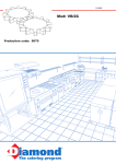
1
ATTIX 751-01/-11/-21
ATTIX 751-2M/-0H
ATTIX 761-21XC/-2MXC
ATTIX 763-21ED/-2MED
ATTIX 791-21/-2M/B1
ATTIX 751-61/-71
ATTIX 19 Gallon/-AE
ATTIX 19 Gallon/AS/PE2
Repair Manual
A. Safety instructions
B. Technical data
C. Components
D. Operation
E. Troubleshooting
F. Spare parts
G. Tools
H. Wiring
Nilfisk
ALTO
Contents
Preface
.....................................................................7
Symbols used to
mark instructions
.....................................................................7
A
Safety instructions
.....................................................................8
B
Technical data
.....................................................................9
C
Components
1
2
3
4
5
Trolley with container and adapter ring....... 12
Cleaner heads............................................. 12
Filter cleaning.............................................. 13
Suction turbines.......................................... 14
Electrical components................................. 15
D
Operation
1
Automatic filter cleaning
(Attix 761/-21XC/-2M / 763-21ED/-2MED
19 Gallon/AS/P2)......................................... 17
EC drive (Attix 791-21/-2M/B1)....................17
EC-3 electronics (Attix 791-21/-2M/B1)........17
Electronic starter,
EC-3 electronics (Attix 791-21)....................17
Electronic flow sensor (Attix 791-2M/B1).....17
Layout of electronic flow sensor EC
(Attix 791-2M/B1).........................................18
Electronic soft start
(Attix 751-01/-11, Attix 19 Gallon)................ 18
Electronic starter with speed control
(Attix 751-21)............................................... 18
Electronic flow metering (Attix 751-0H)....... 18
Electronic flow metering (Attix 751-2M)...... 18
Electronic magnet control (Attix 761-21XC,
763-21ED, 9 Gallon/AS/PE2)...................... 18
Electronic flow sensor XC (Attix 761-2MXC,
763-2MED).................................................. 18
Turbine/temperature monitoring
(Attix 751-61/-71, 19 Gallon AE).................. 19
Electronic level control
(Attix 751-61/-71, 19 Gallon AE).................. 19
Layout of electronic level control
(Attix 751-61/-71, 19 Gallon AE).
21
2
3
4
5
6
7
8
9
10
11
12
13
14
15
E
Troubleshooting
1
ESD (electrostatic discharge)..................... 22
2
Troubleshooting on unit............................... 22
2.1 Unit will not work (all units with
brush motor). ............................................ 22
Attix7_ver.1.0_140105
3/59
Nilfisk
ALTO
Attix7_ver.1.0_140105
Contents
2.2 Unit will not work (all units with
EC drive)...................................................... 23
2.3 Warning sound! (all cleaners)...................... 24
3
Trolley/container...........................................25
3.1 Removing/fitting castors (all models except
Attix 751-71)................................................ 25
3.2 Removing/fitting wheels (all models except
Attix 751-71)................................................ 25
3.3 Removing/fitting feet (Attix 751-71)............. 25
3.4 Removing/fitting wheels (Attix 751-71)........ 26
3.5 Removing/fitting grips (all models except
Attix 751-71)................................................ 26
3.6 Removing/fitting lock (all models)................ 26
3.7 Removing/fitting grip with tensioning band
(all models).................................................. 27
3.8 Removing/fitting belt (all models)................ 28
3.9 Removing/fitting pump (Attix 751-61/-71,
19 Gallon AE).............................................. 29
3.10 Removing/fitting non-return pipe
(Attix 751-61/-71, 19 Gallon AE).................. 29
4
Cleaner head............................................... 30
4.1 Removing/fitting grip (Attix 751-61/-71,
19 Gallon AE).............................................. 30
4.2 Removing/fitting grip (Attix 751-01/-11/-21,
751-2M/-0H, 791-21/-2M/B1, 19 Gallon)..... 30
4.3 Removing/fitting grip (Attix 761-21XC/-2M
XC, 763-21ED/-2MED, 19 Gallon./AS/PE2).30
4.4 Removing/fitting hood (Attix 751-01/-11/-21/
-2M/-0H, 791-21, 751-61/-71, 19 Gallon AE)30
4.5 Removing/fitting hood (Attix 761-21XC/-2MXC,
763-21ED/-2MED, 19 Gallon/AS/PE2)........ 30
4.6 Removing/fitting cooling air filter
(Attix 791-2M/B1).........................................31
4.7 Removing/fitting hood (Attix 791-2M/B1)..... 31
4.8 Removing/fitting locking clamps (Attix
751-01/-11/-21/-2M/-0H, 761-21XC/-2MXC,
763-21ED/-2MED, 751-61/-71,
19 Gallon AE, 19 Gallon/AS/PE) .................32
4.9 Removing/fitting locking clamps
(Attix 791-21)............................................... 32
4.10 Removing/fitting locking clamps
(Attix 791-2M/B1).........................................32
5
Suction turbine.............................................33
5.1 Removing/fitting clamping plate
(Attix 751-01/-11/-21/-2M/-0H/-61/-71,
19 Gallon AE)............................................... 33
5.2 Removing/fitting clamping plate (Attix
761-21XC/-2MXC, 763-21ED/-2MED,
19 Gallon/-AE)............................................. 33
5.3 Removing/fitting clamping plate
(Attix-791-21)............................................... 33
5.4 Removing/fitting clamping plate
(Attix 791-2M/B1).........................................33
4/59
Nilfisk
ALTO
Contents
5.5 Removing/fitting bracket for filter tightener
(Attix 761-21XC/-2MXC,
763-21ED/-2MED, 19 Gallon/AS/PE2)........ 33
5.6 Removing/fitting hose for level monitoring
(Attix 761-21XC/-2MXC,
763-21ED7-2MED, 19 Gallon/AS/PE,
751-61/-71, 19 Gallon AE)........................... 33
5.7 Removing/fitting motor carbon brushes
(all models except with EC drive)................ 34
5.8 Removing/fitting motor (all models except
with EC drive).............................................. 34
5.9 Checking motor, removing/fitting motor
(Attix 791-21/-2M/B1)...................................34
6
Automatic filter cleaning
(Attix 761-21XC/-2MXC, 763-21ED/-2MED,
19 Gallon/AS/PE2).......................................34
7
Electrical...................................................... 35
7.1 Removing/fitting electrical components....... 35
7.2 Removing/fitting power cord (Attix 751-01/-11
-21/-0H/-2M/-61/-71, 791-21, 19 Gallon AE)35
7.3 Removing/fitting power cord (Attix 761-21XC/
-2MXC, 763-21ED/-2MED, 19 Gal/AS/PE2).35
7.4 Removing/fitting socket (Attix 791-2M/B1)...35
7.5 Removing/fitting power cord
(Attix 791-2M/B1).........................................36
7.6 Checking electronic flow metering EC in
manual mode (Attix 791-2M/B1).................. 37
7.7 Checking electronic flow metering EC in
automatic mode (Attix 791-2M/B1).............. 38
7.8 Checking flow sensor detection (performance)
of electronic flow metering
(Attix 751-2M/-0H, 761-2MXC, 763-2MED,
791-2M/B1).................................................. 39
7.9 Checking and calibration (adjustment)
of flow sensor (Attix 751-2M/-0H, 7612MXC, 763-2MED, 791-2M/B1)................... 39
7.10 Removing/fitting electronic flow metering EC
(Attix 791-2M/B1).........................................39
7.11 Checking electronic level control in manual
mode (Attix 751-61/-71,19 Gallon AE)......... 40
7.12 Checking electronic level control in
automatic mode (Attix 751-61/-71,
19 Gallon AE)...............................................41
7.13 Calibrating electronic level control
(Attix 751-61/-71, 19 Gallon AE).................. 43
7.14 Removing/fitting electronic level control
(Attix 751-61/-71, 19 Gallon AE).................. 43
7.15 Checking temperature sensor
(Attix 751-61/-71, 19 Gallon AE).................. 44
7.16 Removing/fitting temperature sensor/
flow sensor (Attix 751-61/-71/-2M/-0H,
19 Gallon AE, 763-2MED, 791-2M/B1).........44
Attix7_ver.1.0_140105
5/59
Nilfisk
ALTO
Contents
7.17 Checking, removing/fitting electronic soft
start (Attix 751-01/-11, 19 Gallon)................ 44
7.18 Checking, removing/fitting electronic EA
with speed control (Attix 751-21)................. 44
7.19 Checking, removing/fitting electronic flow
metering (Attix.751-2M/-0H)........................ 44
7.20 Checking, removing/fitting electronic magnet
control (Attix 761-21XC, 763-21ED,
19 Gallon/AS/PE2).......................................44
7.21 Checking level monitoring
(Attix 761-21XC/-2MXC, 763-21ED/-2MED,
19 Gallon/AS/PE2)......................................44
7.22 Checking, removing/fitting electronic flow
sensor XC (Attix 761-2MXC, 763-2MED).... 45
7.23 Potentiometer (hose diameter)
(Attix 751-2M, 761-2MXC, 263-2MED,
791-2M/B1).................................................. 45
7.24 Checking piezo buzzer (Attix 751-2M/-0H,
761-2MXC, 763-2MED, 791-2M/B1)............45
7.25 Checking, removing/fitting electronic EA.
with speed control EC-3 (Attix 791-21)........ 45
7.26 Checking, removing/fitting electronic EC-3
(Attix 791-21/-2M/B1)...................................45
7.27 Checking, removing/fitting RFI filter/
varistor (Attix 791-21/-2M/B1)......................45
F
Spare parts
............................................................................. 46
G
Tools
1
Special-purpose tools.................................. 47
H
Wiring
1
2
3
4
5
6
Wiring diagram (Attix 751-01)...................... 48
Wiring diagram (Attix 751-11, 19 Gallon)..... 49
Wiring diagram (Attix 751-21)...................... 50
Wiring diagram (Attix 751-2M)..................... 51
Wiring diagram (Attix 751-0H)..................... 52
Wiring diagram (Attix 761-21XC,
763-21ED)................................................... 53
Wiring diagram (Attix 761-2MXC,
763-2MXC).................................................. 54
Wiring diagram (Attix 791-21)...................... 55
Wiring diagram (Attix 791-2M/B1)................56
Wiring diagram (Attix 751-61,
19 Gallon AE)...............................................57
Wiring diagram (Attix 751-71)...................... 58
Wiring diagram (Attix 19 Gallon AS/PE2).... 59
7
8
9
10
11
12
Attix7_ver.1.0_140105
6/59
Nilfisk
ALTO
In this manual you will find
the essentials you need
to know when repairing
wet and dry cleaners of
the Attix 7 and 19 Gallon
series.
When carrying out repairs, make sure you
have a suitable workbench or the like with the
necessary power supply
available.
If you determine an error
in operation, be sure to
refer the customer to the
user manual.
Preface
A fault in the equipment
can have a number of causes. Chapter E Troubleshooting will help you
here.
Use the illustrated spare
parts lists for your repairs.
These show you the location of the individual parts
and the sequence in which
they are assembled.
Read the technical information sheets. These will
tell you about any technical modifications made
after publication of this
repair manual.
Technical information
sheets are a supplement
to the spare parts list until
a follow-on publication.
Repair manuals and technical information sheets
should be available at the
site where repairs are carried out. Further repair
manuals of the Attix series
may be necessary for
repairs to the equipment.
It is not permitted to give
them to third parties.
Use original Nilfisk
ALTO spare parts only!
Safety instructions marked with this symbol in
this manual must be observed to prevent danger
to persons.
Symbols used to mark instructions
This symbol is used to
mark safety instructions
that must be observed to
prevent damage to the
equipment and degradation of performance.
Attix7_ver.1.0_140105.
☞
This symbol indicates tips
and instructions to simplify work and to ensure safe
operation.
7/59
Safety instructions
For your own safety
A
Observe national safety
directives and regulations
for the electrical engineering trade, in particular:
IEC 60335-2-69
EN 60335-2-69
Repairs should only be
made by someone who
has received proper
instructions for the job
or who is a qualified electrician.
DIN VDE 105 part 1:
operation of electrical
power installations
DIN VDE 0701/0702:
repair, modification and
testing of electrical installations
Before starting the equipment, be sure to read the
accompanying service
manual, and keep it close
as ready reference.
The equipment should
only be used by persons
who have been instructed
in its use and are authorized to do so.
E S D ( e l e c t r o s ta t i c
discharge)
Observe the following ESD precautions before any
repair of or near electronic parts:
• Touch the protective conductor to discharge your own
body.
• Possibly wear an anti-static wrist strap.
• Use a conducting floor or tabletop.
• Never touch a circuit board or electronic components,
always hold them by the plastic or insulation.
• Transport electronic parts in conductive packaging
(e.g. special ESD packages).
Attix7_ver.1.0_140105
8/59
Safety Instructions
Nilfisk
ALTO
751-01
ZA
Voltage
Frequency
Fusing
Power consumption PIEC
Connected load for
appliance socket
Total connected load
Power cord lenght
EU
230
V
Hz
A
W
751-21 751-2M
751-11
GB
DK CH GB 110V
230V
110
16
10
25
1200
EU
EU
751-0H
EU
DK
EU
761-21 XC
GB
DK
110V
110
10
16
10
230
50/60
16
13
1000
25
13
1200
W
-
2400
1100
1550
1800
2400
-
2400
1100
1550
1800
W
m
-
3600
2300
2750
3000
10
3600
-
3600
2300
2750
3000
10
7,5
H05RR- H05RR- H05RR- H07BQ-F
F3G0,75 F3G1,5 F3G1,0 3G2,5
Power cord type
7,5
H05RRF3G1,5
H07RN- H05RR- H05RR- H05RR- H07BQ-F H05RRF3G1,5 F3G1,0 F3G1,5 F3G1,0 3G2,5 F3G1,5
I
Protection
I
Dimensions
and wight
II
Width
Depth
Hight
Weight
Tank volume
mm
mm
mm
kg
l
Unit-specific
data
II
Protection class
Protection category
RFI suppression
Air volume flow (max)
Static wate lift (max)
Sound pressure level at
1m, EN 60704-1
l/min
Pa
3600
23000
3100
20000
3600
23000
dB(A)
64
60
64
IPX4
EN 55014-1
dB(A)
580
605
970
25
27
70
B
Operating noise
GB
230V
230
Technical Data
Electrical data
Attix
Nilfisk
ALTO
Attix7_ver.1.0_140105
Version /
Type
National
Variants
57
Technical data
9/59
Voltage
Frequency
Fusing
Power consumption PIEC
Connected load for
appliance socket
Total connected load
Power cord lenght
V
Hz
A
W
791-2M/B1
763-21 ED
761-2M XC
763-2M ED
791-21
EU
EU
EU
EU
EU
230
230
230
230
230
50/60
751-61
GB
110V
110
16
GB
EU DK CH
230V
230
230
25
13
1550
1800
16
10
751-71
EU
230
16
1200
W
2400
W
m
3600
1850
3000
7,5
10
10(FI)
H05RR- H05RR- H07RNH07RNH07BQ-F 3G2,5
F3G1,5 F3G1,0 F3G1,5
F3G1,5
2750
7,5
H05RRF3G1,5
Power cord type
650
Protection
Dimensions
and wight
Width
Depth
Hight
Weight
Tank volume
mm
mm
mm
kg
l
Unit-specific
data
I
IPX4
EN 55014-1
Protection class
Protection category
RFI suppression
Air volume flow (max)
Static wate lift (max)
l/min
Pa
3600
23000
Sound pressure level at
1m, EN 60704-1
Operating noise
dB(A)
64
dB(A)
57
580
605
1284
17
30
970
27
70
1280
17
30
970
25
33
480
510
875
31
Technical Data
Electrical data
Attix
Nilfisk
ALTO
Attix7_ver.1.0_140105
Version /
Type
National
Variants
70
B
Technical data
10/59
Voltage
Frequency
Fusing
Power consumption
Connected load for
appliance socket
Total connected load
Power cord lengt
19 Gallon-AS/PE2
120
60
15
V
Hz
A
HP
1,4
1,1
1,4
HP
0,5
0,8
0,5
HP
ft
Power cord type
Protection
19 Gallon-AE
Technical Data
Electrical Data
19 Gallon
Attix
Nilfisk
ALTO
1,9
25
35
25
SJTW-A
AWG14/3
SJTW-A AWG14/3
SJTW-A
AWG14/3
I
Protection class
IPX4
Protection category
EN 55014-1
RFI suppression
Dimensions
and weight
23
24
38
Width
Depth
Height
Weight
Tank volume
in
in
in
ib
gal
Unit-specific
data
Attix7_ver.1.0_140105
Version /
Type
Volume flow (air)
Static water lift
Sound pressure level at
1m EN 60704-1
Operating noise
cfm
in
127
93
dB(A)
64
dB(A)
57
55
73
60
19
B
Technical data
11/59
Nilfisk
ALTO
1
Components
C
Trolley with container and adapter ring
1) Base frame
2) Adapter ring
3) Container
4) Belt
1
2
4
Attix7 3516
2
Cleaner heads
Attix5 0602
Attix 751-01,-0H
Attix7_ver.1.0_140105
Attix5 0601
Attix 751-11/-21, Attix 19 Gallon
Attix 761-21XC
Attix 791-21
12/59
Components
3
Components
Attix7 3508
Attix5 2903
Attix 19 Gallon/AS/PE2XC
Attix 751-2M
Attix 761-2MXC
Attix 763-2MED
Attix7 3608
Attix7 3517
Attix 791-2M/B1
3
Filter cleaning
C
Attix 751-61/-71
Attix 19 Gallon AE
All units with automatic filter cleaning.
Filter cleaning with the Attix 7 is the same as for the
Attix 560-XC (see repair manual Attix 550/560, section
“Components” page 13).
Attix7_ver.1.0_140105
13/59
Components
Nilfisk
ALTO
Nilfisk
ALTO
4
Components
C
Suction turbines
Attix5-0445
Attix5-2913
Attix 761-21XC/-2MXC
Attix 763-2M ED
Attix 19 Gallon/AS/PE2XC
Attix EC-2809
Attix 791-21
Attix 791-2M/B1
Attix7_ver.1.0_140105
14/59
Components
Attix 751-01/-11/-21/-2M/-0H/-61/-71
Attix 19 Gallon/-AE
Nilfisk
ALTO
Electrical components
Attix7 3634
Attix7 3631
Electronic flow metering EC
Attix 791-2M/B1
Electronic level control
Attix 751-61/71
The following Attix 7 models are fitted with the same electronic circuitry used in
other units:
Attix
751-01/-11
19 Gallon
751-21
Electronic Electronic
Electronic Electronic flow
Electronically
magnet
soft start EA
identical to Attix
metering contol
550-01,
12 Gallon
X
550-21,
12 Gallon RDF
X
751-2M
X
550-2M/-2H
X
550-0H
751-0H
761-21XC,
763-21ED,
19Gallon/AS/
PE
761-2M/XC,
763-2M/ED
791-21
X
X
X
Attix7_ver.1.0_140105
See section
"Components" in
repair manual
Attix 550/560
page 14
Attix 550/560
page 14
Attix 550/560
page 14
Attix 550/560
page 14
560-21XC,
Attix 550/560
12 Gallon RDFD page 14
Attix 550/560
560-2MXC/-2HXC page 14
590-21,
Attix 590-21
12 Gallon EC
page 8
15/59
Components
5
C
Components
Nilfisk
ALTO
Components
Attix7-2360
Attix7-3640
PRCD circuit-breaker
Attix 751-71
Components
GFCI circuit-breaker
Attix 19 Gallon-AE
C
Attix7-3638
Submersible pump
Attix 751-61/-71
Attix 19 Gallon AE
Attix7_ver.1.0_140105
16/59
Nilfisk
ALTO
D
Operation
The following Attix 7 functions are identical to other models:
791-21 /2M/B1
791-21
X
2
3
4
5
Function of EC.drive
X
Technical description
of electronic EC-3
X
Technical description
of electronic EA. EC-3
X
see section
Function
"Operation" in
identical to Attix repair manual
560-21/-2M/-2H,
12 Gallon RDFD
Attix 550/560
590-21,
12 Gallon EC
Attix 590-21
590-21,
12 Gallon EC
Attix 590-21
590-21,
12 Gallon EC
Attix 590-21
Electronic flow sensor EC (Attix 791-2M/B1)
Alto no.: 302001710
(200–230 Vac/50–60 Hz)
Alto no.: 302001709
(100–120 Vac/50–60 Hz)
Several functions are
integrated on this circuit
board:
- M a i n s w i t c h
Man - 0 - Auto ‘
- Speed control
- Remote control of EC
drive
- Soft start
- Automatic starter for
electrical tools
- Flow detection by flowsensor
- Setting of different hose
diameters
LED functions:
Green LED flashes:
unit on standby
Green LED on:
flow > 22 m/s
Yellow LED on:
flow > 20 m/s and < 22
m/s
Main switch, speed control, automatic starter:
as described in Attix
550/560 repair manual
section D.
Soft start:
the motor always makes a
soft start.
Operating data:
saved operating data can
be read out on the Alto terminal (no. 301 000 383 for
operating data retrieval).
Flow sensor:
as described in Attix
550/560 repair manual,
section D.
Red LED on:
flow < 20 m/s plus buzzer
sounds
Attix7_ver.1.0_140105
17/59
Operation
1
Attix
Function of automatic
filter cleaning system
761-21XC/-2MXC
763-21ED/-2MED 19 791-21 /Gallon AS/PE2
2M/B1
Nilfisk
ALTO
6
D
Operation
Layout of electronic flow sensor EC (Attix 791-2M/B1)
Motor
terminal
Main switch
Plug-in jumper
self-calibration
L1
LED red
L1
LED yellow Socket
outlet
LED green litz wire
Power line
N
N
Hose
diameter
potentiometer
Operating
data
readout
Speed
potentiometer
Calibration
button
1
Soldering
jumper
SJ1
Terminal
flow sensor
302000428
Terminal
compressed air
flow monitor
Terminal
piezo
buzzer
6
Connector for
remote control
of EC drive
7
8
Attix
Technical
description of
electronic
softstart
Technical
description of
electronic
automatic starter.
751-01/-11
19 Gallon 751-21 751-0H 751-2M
761-21XC
763-21ED
19 Gal./AS/PE2
761-2MXC
763-2MED
X
X
9
Technical
description of
electronic flow
measurment
10
Technical
description of
electronic flow
measurment
11
Technical
description of
electronic magnet
control
Technical
description of
electronic flow
measurement XC
12
Attix7_ver.1.0_140105
X
X
Function
identical to
Attix
See section
"Operation" in
repair manual
550-01
12 Gallon
Attix 550/560
550-21
12 Gal.RDF
Attix 550/560
550-0H
Attix 550/560
550-2M/-2H
Attix 550/560
550-21
12 Gal.RDFD Attix 550/560
X
X
560-2MXC/2HXC
Attix 550/560
18/59
Operation
The following Attix 7 functions are identical to other models:
Nilfisk
ALTO
13
D
Operation
Turbine / temperature monitoring (Attix 751-61/-71,19 Gallon AE)
A sensor in the exhaust air duct (like flow sensor)
measures the temperature of the air from the turbine.
If the turbine reaches a temperature of more than
85°C, motor speed is reduced.
Electronic level control
(Attix 751-61/-71, 19 Gallon AE)
Alto no.: 302001712
(200–230 Vac/50–60 Hz)
Alto no.: 302001711
(100–120 Vac/50–60 Hz)
Several functions are integrated on this circuit
board:
- Main switch Pump Auto - 0 - Man
- Speed control in manu
al
- Soft start
- Level control
- Turbine temperaturemonitoring
Main switch:
this allows selection of
three modes.
LED functions:
Green LED (D2) on:
operating voltage applied
Pump:
momentary contact for
emptying the container.
One-time operation
causes the pump to run for
30 s.
Green LED (D6) on:
pump on
Man:
the turbine immediately
starts.
Auto:
the turbine and pump are
controlled as a function of
the level.
Speed control:
the integrated speed control only works in Man
mode. The control range
is 90° to 130°.
Advantages:
- Optimal matching of
suction capacity to the
application
- Prolonged turbine service life
- Reduced noise emission
- Power savings
Green LED (D7) on:
motor on
Red LED (D3) flashes:
microprocessor working
Red LED (D5) on:
level - turn off motor
Yellow LED (D4) on:
level - turn on pump
Operating data:
saved operating data can
be read out on the Alto terminal (no. 301 000 383 for
operating data retrieval).
Continued on page 20
Attix7_ver.1.0_140105
19/59
Operation
14
Nilfisk
ALTO
Operation
D
Level control:
Level control by means of a pressure sensor is implemented to optimize working with the equipment. The level in the container is metered in a rubber baffle pipe.The pressure sensor measures the difference in pressure between the container and the baffle pipe. Rising
water level increases the pressure in the pipe. The pressure in the baffle pipe increases linearly with water level.
Man mode:
The electronic circuitry cuts out the turbine upwards of
a defined pressure (water level), and remains in this
status until the cleaner is turned off and the container
emptied. The pump cannot be started in manual
mode. The power of the turbine can be altered by
speed control.
Pump mode:
The Pump switch setting is a momentary contact (automatic reset). One-time actuation causes the pump to
work for 30 s. This function can be used to completely
empty the container. At the same time this is a safeguard
against the pump running when it is dry.
Attix7_ver.1.0_140105
20/59
Operation
Auto mode:
Only the suction turbine runs when there is no water in
the container. When the container fills with water, the
pump is turned on. If more water flows into the container
than the pump can convey out of the container, the level
continues to rise. To prevent overfilling, the suction turbine is cut out at maximum level. As soon as the water level is significantly reduced by the pump, the suction motor is cut in again. Upon total emptying of the container,
the pump is cut out with a time delay.
L1
Power line
N
LED green
Motor on (D7)
Speed
potentiometer
Terminal 2
Motor
Terminal 1
Motor
LED green
Pump on
(D6)
Calibration
button
LED red(D3)
Info
LED yellow
Level pump
on (D4)
LED red
Motor off
(D5)
Reserve. LED
LED green
(D2)
Read out
operating
data
Temperature
sensor
B2
Pressure sensor
L1
Socket
terminal
Pump
N
21/59
Attix7_ver.1.0_140105
Operation
Layout of electronic level control (Attix 751-61/-71, Attix 19 Gallon AE)
15
D
Operation
Nilfisk
ALTO
ESD (electrostatic discharge)
Observe the following
ESD precautions before
any repairs to electronic
circuitry:
2
- Touch the protective con
ductor to discharge sta
tic from your own body.
- Possibly wear an antistatic wrist strap.
- Use a conductive floortabletop.
- Never touch a circuit
board or electronic com
ponents, always hold
them by the plastic or in
sulation.
- Transport electronic
parts in conductive pa
ckaging (e.g. Special
ESD packages).
Troubleshooting on unit
2.1 Unit will not work
(all units with brush motor)
Voltage applied to
switch?
No
Start:
line voltage must be present
and plug must be plugged
in.
Check plug and power
cord, replace if
necessary.
Do electronics work?
No
Conduct safety check.
Yes
Replace electronics.
Yes
Does motor work?
No
Repair or replace motor.
No
Ye s
Yes
1
E
Troubleshooting
Does cleaner work?
Attix7_ver.1.0_140105
22/59
Troubleshooting
Nilfisk
ALTO
Nilfisk
ALTO
E
Troubleshooting
Troubleshooting
2.2 Unit will not work (all units with EC drive)
Start:
line voltage must be
present and plug must be
plugged in.
Voltage applied to
switch?
No
Check plug and power
cord, replace if
necessary.
Voltage applied to EC3 electronics? (See
check of EC-3
electronics)
No
Check electronics/
board and RFI filter,
replace if necessary .
No
Replace
electronics.
No
C h e c k E C m o t o r,
replace if necessary.
Conduct safety check.
Yes
Yes
Do EC-3 electronics
work? (See check of
EC-3 electronics)
EC-3
Yes
Yes
Does EC motor work?
No
Yes
Does cleaner work?
Attix7_ver.1.0_140105
23/59
2.3 Warning sound!
(all cleaners)
Remove hose from container fitting.
E
Troubleshooting
Start:
switch on “I” for full power, potentiometer set to correct hose diameter, unit in normal cleaning mode.
Warning
gone.
Troubleshooting
Nilfisk
ALTO
Check if hose or
nozzle is
clogged.
Warning still
sounds.
Remove filter bag from
container.
Warning
gone.
Insert new filter
bag.
Warning still
sounds.
Conduct safety check.
Check filter, replace if
necessary.
Warning still
sounds.
Check flow sensor, replace if necessary.
Warning still
sounds.
Attix7_ver.1.0_140105
No
Check flow sensor detection (function), i.e.
electronic flow metering, replace electronics
if necessary.
Check adjustment of
flow sensor, recalibrate
if necessary.
Yes
Warning still
sounds.
Performance check of
flow sensor: OK?
24/59
Nilfisk
ALTO
E
Trolley/container
3.1 Removing/fitting castors (all models except Attix 751-71)
1. Use an Allen key (5 mm)
to undo the countersunk
head screw (1), and remove the castor.
2. Fit in the reverse order.
1
Attix7 3647
3.2 Removing/fitting wheels (all models except Attix 751-71)
1. Lever off the wheel cap
(1) with a screwdriver, and
remove the wheel.
1
2. Fit in the reverse order.
Attix7 3648
3.3 Removing/fitting feet (Attix 751-71)
1
1. Take the container out
of the base frame, and
raise the frame by laying
the handle on the floor.
2. Unscrew the nut (1),
and remove the foot with
the screw.
Attix7 3649
Attix7_ver.1.0_140105
3. Fit in the reverse order.
25/59
Troubleshooting
3
Troubleshooting
Nilfisk
ALTO
Troubleshooting
E
1. Lever off the wheel cap
(1) with a screwdriver.
1
2
2. Lever the clamping ring
(2) off the axle with a
screwdriver, and remove
the wheel.
Attix7 3650
☞
3. Fit in the reverse order.
Do not push the clamping
ring too far onto the axle
otherwise the wheel will
not turn freely.
3.5 Removing/fitting grips (all models except Attix 751-71)
1
1
1
1
1. Undo the six screws (1)
with a Phillips screwdriver,
and remove the grips.
2. Fit in the reverse order.
1
1
Attix7 3652
3.6 Removing/fitting lock (all models)
1. Lever off the lock (1)
with a screwdriver.
2. Fit in the reverse order,
pressing the lock (1) firmly
over the latch so that you
hear it snap into place.
1
Attix7 3655
Attix7_ver.1.0_140105
26/59
Troubleshooting
3.4 Removing/fitting wheels (Attix 751-71)
Nilfisk
ALTO
Troubleshooting
E
1. Take the cleaner head
with the adapter ring off
the container, and lift the
container out of the base
frame.
4
1
1
Attix7 3657
5
2
3
1
1
Attix7 3659
2. Mark (1) the position of
the grip (4) and the facing
stop (5) on the container.
3. Undo the screw (2) on
the tensioning band (3)
with a screwdriver, and remove the grip (4) and tensioning band (3).
4. Fit in the reverse order,
placing the grip (4) and
stop (5) between the markings and lightly tightening
the screw (2) on the tensioning band (3).
5. Set the container in the
base frame, and lock it in
place.
7
7
Attix7 3660
6. Align the grip (4) and
stop (5) on the container in
the base frame (7), and
firmly tighten the screw (2)
on the tensioning band
(3).
7
7
6
Attix7 3661
☞
Attix7_ver.1.0_140105
Note:
The contact faces of the
contact spring (6) must be
clean and free of corrosion.
27/59
Troubleshooting
3.7 Removing/fitting grip with tensioning band (all models)
Nilfisk
ALTO
Troubleshooting
E
1. Take the cleaner head
with the adapter ring off
the container, and lift the
container out of the base
frame.
2
1
Attix7 3663
2. Mark the position of the
belt on the container (1).
3. Take out the C-coupling
(2) with a long screwdriver
(only cleaners used by fire
brigades).
4
6
4. Thread a normal length
of cord (3) or the like (6080 cm) through one of the
loops (4) of the tensioning
device, and pull the loop
(4) back over the catch
(6). Detach the second
loop (4) in the same way,
and take off the belt (7).
6
3
4
7
Attix7 3662
☞
Attix7_ver.1.0_140105
5. Fit in the reverse order,
making sure the belt (7) is
correctly positioned.
Note:
On cleaners used by fire
brigades, always fit the Ccoupling (2) first as a positioning aid.
28/59
Troubleshooting
3.8 Removing/fitting belt (all models)
Nilfisk
ALTO
E
Troubleshooting
Troubleshooting
3.9 Removing/fitting pump (Attix 751-61/-71, Attix 19 Gallon AE)
4
3
1
Attix7 3664
1. Take the cleaner head
with the adapter ring off
the container, and lift the
container out of the base
frame..
3. Disassemble the plug
(1) of the pump (3), undo
the cable fixture (4) on the
container, pull the cable
through, and take out the
pump.
2. Take out the C-coupling
(see 3.8/3, page 27).
Fit in the reverse order.
3.10 Removing/fitting non-return pipe (Attix 751-61/-71, Attix 19 Gallon AE)
1. Remove the pump (1)
(see 3.9, page 28).
2
1
2. Unscrew the non-return
pipe (2) from the threaded
fitting of the pump (1), and
remove it.
3. Fit in the reverse order.
Attix7 3668
☞
Attix7_ver.1.0_140105
Note:
The threaded fitting can
be sealed with normal
silicone.
29/59
Nilfisk
ALTO
E
Troubleshooting
4.1 Removing/fitting grip (Attix 751-61/-71,19 Gallon AE)
As explained in the Attix
550/560 repair manual,
section E, page 36. But
first unscrew the clamping
fixtures right and left (1).
1
1
Attix7 3611
The following repairs are identical as with other models.
Attix
751-01/-11/-21
751-2M /-0H
791-21/-2M /B 1
19 G a llo n
761-21X C
761-2M X C
763-21ED
763-2M ED
Id e n tica l to
19 G a l./AS /P E2 Attix
4 .2 Re m o vin g /
fittin g g rip
550-01
12 G allon
X
4 .3 Re m o vin g /
fittin g g rip
Attix
X
751-01/-11/-21
751-2M /-0H
791-21/-2M /B 1
19 G a llo n -AE
751-61/-71
4 .5
fittin g h o o d
Re m o vin g /
fittin g h o o d
Attix7_ver.1.0_140105
X
X
A ttix 550/560
page 36
560-21
A ttix 550/560
12 G al.R DF D page 37
761-21X C
761-2M X C
763-21ED
763-2M ED
Id e n tica l to
19 G a l./AS /P E2 Attix
4 .4 Re m o vin g /
S e e se ctio n
"T ro u b le sh o o tin g "
in re p a ir m a n u a l
550-01
12 G allon
560-21
12 G al.R DF D
S e e se ctio n
"T ro u b le sh o o tin g "
in re p a ir m a n u a l
A ttix
page
A ttix
page
550/560
36
550/560
37
30/59
Troubleshooting
4. Cleaner head
Nilfisk
ALTO
Troubleshooting
E
1. Undo the screw (1) with
an Allen key (5 mm), and
take off the cover.
1
Attix7 3612
2. Pull off the filter insert
(2) forwards.
3. Undo the four screws
(3) with a Phillips
screwdriver, and take off
the filter case.
3
3
3
2
4. Fit in the reverse order.
3
Attix7 3616
4.7 Removing/fitting hood (Attix 791-2M/B1)
4
4
1. Unscrew the cooling air
filter (see 4.6).
3
3
4
4 Attix7 3625
2. Unscrew the socket
(see 7.4).
3. Undo the two screws (3)
with an Allen key (5 mm),
and take off the grip.
4. Undo the four screws
(4) of the locking clamps
with a Phillips screwdriver,
and take off the hood.
5. Fit in the reverse order.
Attix7_ver.1.0_140105
31/59
Troubleshooting
4.6 Removing/fitting cooling air filter (Attix 791-2M/B1)
Nilfisk
ALTO
E
Troubleshooting
4.8
Attix
Re m oving / fitting
locking cla m ps
All m ode ls
e x ce pt
Ide ntica l to
791-21/-2M /B1 791-21 Attix
X
4.9 Re m oving / fitting
locking cla m ps
X
S e e se ction
"Trouble shooting"
in re pa ir m a nua l
550-01
560-21
A ttix
12 G allon/-RDFD page
A ttix
590-21
page
550/560
45
590-21
18
4.10 Removing/fitting locking clamps (Attix 791-2M/B1)
Attix7_ver.1.0_140105
1. Remove the hood (see
4.7).
3. Pull the locking clamps
upwards and off.
2. Take off the clamping
plate (see Attix 590-21EC
repair manual, section E).
4. Fit in the reverse order.
32/59
Troubleshooting
The following repairs are identical as with other models.
Nilfisk
ALTO
E
Troubleshooting
The following repairs are identical as with other models.
Attix
751-01/-11/-21
751-2M/-0H
19 Gallon-AE
751-61/-71
761-21XC
761-2MXC
763-21ED
763-2MED
Identical to
19 Gal./AS/PE2 791-21 Attix
See section
"Troubleshooting"
in repair manual
5.1 Removing /
5.2
fitting clamping
plate
Removing /
fitting clamping
plate
550-01
Attix 550/560
12 Gal./-RDFD page 38
X
560-21
Attix 550/560
12 Gal./-RDFD page 39
X
5.3 Removing /
fitting clamping
plate
X
590-21
Attix 590-21
page 18
5.4 Removing / fitting clamping plate (Attix 791-2M/B1).
1. Remove the hood (see
4.7).
3. Fit in the reverse order.
2. Remove the clamping
plate (see Attix 590-21EC
repair manual, section E).
The following repairs are identical as with other models.
Attix
5.5 Re m oving / fitting
bra cke t for filte r
tighte ne r
5.6 Re m oving / fitting
hose for le ve l
m onotoring
Attix7_ver.1.0_140105
761-21X C
761-2M X C
761-21X C
763-21ED
761-2M X C
763-2M ED
763-21ED
19
763-2M ED
Ga l./AS /P E2
19
751-61/-71
Ide ntica l to
Ga l./AS /P E2 19 Ga llon AE Attix
S e e se ction
"Trouble shooting"
in re pa ir m a nua l
560-21
A ttix 550/560
12 Gal./-RDFD page 40
X
X
560-21
A ttix 550/560
12 Gal./- RDFD page 40
33/59
Troubleshooting
5. Suction turbine
Nilfisk
ALTO
E
Troubleshooting
Attix
5.7 Removing /
fitting motor
carbon brushes
Removing
/
5.8
fitting motor
5.9 Checking motor,
removing / fitting
motor
761-21XC
761-2MXC
All models
763-21ED
See section
except
"Troubleshooting"
those with 791-21/- 763-2MED
EC-drive 2M/B1 19 Gal./AS/PE2 Identical to Attix in repair manual
X
X
X
6 Automatic filter
cleaning
Attix7_ver.1.0_140105
X
560-21
12 Gallon/- RDFD
560-21
12 Gallon/- RDFD
Attix 550/560
page 41
Attix 550/560
page 41
590-21EC
Attix 590-21
page 19-20
560-21
Attix 550/560
12 Gallon/- RDFD page 42-44
34/59
Troubleshooting
The following repairs are identical as with other models.
7
E
Troubleshooting
Electrical
Following repairs or servicing, perform a thorough
electrical check.
Caution!
Make sure the power plug
is pulled out while you are
carrying out repairs.
☞
7.1 Removing / fitting
electrical components
Caution!
Work with the appropriate
wiring diagram (see section H). It is helpful if you
make a sketch to clearly
show which cable (note
the color) matches which
terminal.
The following repairs are identical as with other models.
Attix
7.2 Removing /
fitting power
cord
7.3 Removing /
fitting power
cord
751-01/-11/-21
751-2M/-0H
19 Gallon/-AE
751-61/-71
791-21
761-21XC
761-2MXC
763-21ED
763-2MED
19 Gal./AS/PE2
550-01
12 Gallon/- RDF
X
2
2
2
2
1
Attix7 3623
1. Use a screwdriver to
take off the cover frame
(1).
Attix7_ver.1.0_140105
Attix 550/560
page 45
560-21
Attix 550/560
12 Gallon/- RDFD page 45
X
2
7.4 Removing/fitting
socket
Attix 791-2M/B1
See section
"Troubleshooting"
Identical to Attix in repair manual
2
Attix7 3624
2. Undo the six screws (2)
holding the cover with a
Phillips screwdriver, and
take off the cover.
35/59
Troubleshooting
Nilfisk
ALTO
Troubleshooting
3. Disconnect the cable on
the socket (3), undo the
two screws (4) with a Phillips screwdriver, and take
off the case.
4
4
E
4. Fit in the reverse order.
3
Attix7 3620
7.5 Removing/fitting power cord (Attix 791-2M/B1)
1. Remove the hood (see 4.7).
2. Remove the power cord (see Attix 590-21EC repair
manual, section E, page 21).
Attix7_ver.1.0_140105
36/59
Troubleshooting
Nilfisk
ALTO
Nilfisk
ALTO
Troubleshooting
E
Troubleshooting
7.6 Checking electronic flow metering EC in manual mode
(Attix 791-2M/B1)
Lamp
EC electronics
302000764
L1
LED red
LED yellow
LED green
Power line
N
1. Make sure the unit is isolated from the power.
2. Remove the hood (see 4.4).
3. Set the cleaner head on a clean container
(w/o a filter bag) and withdraw the hose from the
container fitting.
4. Apply line voltage and set the switch to “I”.
Visual check:
Green LED on = EC electronics driven, air flow OK.
Yellow LED on = EC electronics driven, air flow
reduced.
Red LED on = EC electronics driven, air flow too low.
5. Make sure the unit is isolated from the power.
6. Withdraw the two cables for the EC electronics on
the switch and connect the lamp 302000764.
7. Apply line voltage and set the switch to “I”.
Check:
Lamp “EC electronics” illuminates immediately.
Red LED illuminates and warning sounds.
Ja - “MAN” mode OK.
“MAN” OK?
Attix7_ver.1.0_140105
No -replace electronic and
recalibrate
37/59
Nilfisk
ALTO
E
Troubleshooting
Terminal
EC electronics
Troubleshooting
7.7 Checking electronic flow metering EC in automatic mode
(Attix 791-2M/B1)
Lamp
Tool
302000765
L1
LED red
LED yellow
Power line
LED green
N
1. Make sure the unit is isolated from the power.
2. Remove the hood (see 4.4).
3. Set the cleaner head on a clean container
(w/o a filter bag) and withdraw the hose from the
container fitting.
4. Insert the “tool” lamp in the socket (302000765) and
rotate the bulb one turn out of the receptacle.
5. Apply line voltage and set the switch to “Auto”.
6. Visual check:
Green LED flashes (standby).
7. Check:
Turn the bulb properly into the receptacle. The “tool”
lamp illuminates immediately, and the motor starts.
The red, yellow and green LEDs illuminate.
The red and yellow LEDs extinguish after 3-5 s.
Rotate the bulb one turn out of the receptacle.
The motor stops (runs on) after 3-5 s.
Yes - “Auto” Mode OK.
“Auto” Mode OK?
No - Replace electronic
and recalibrate
Attix7_ver.1.0_140105
38/59
Nilfisk
ALTO
E
Troubleshooting
Attix
Checking
flow sensor
7.8
detection (performance) of
electronic flow metering
751-2M/-0H
761-2MXC
763-2MED1
791-2M/B1
Identical to Attix
See section
"Troubleshooting"
in repair manual
X
550-2M/-0H
Attix 550/560
page 54
X
550-2M/-0H
Attix 550/560
page 55-56
7.9 Checking and calibration
(adjustment) of flow
sensor
7.10 Removing/fitting electronic flow metering EC (Attix 791-2M/B1)
2
2
2
2
2
2
2
Withdraw the plug for the
speed control from the EC
electronics.
3
4
4
Attix7 3633
1. Remove the hood (see
4.7).
2. Disconnect the power
cord, cables to EC electronics, flow sensor, buzzer,
and potentiometer from
the electronics. Disconnect L1 and N on the
socket (2).
Attix7_ver.1.0_140105
Attix7 3630
3. Undo the retaining
screw (3) on the rotary
knob with a Phillips
screwdriver, and remove
the rotary knob.
4. Undo the two retaining
screws (4) behind the rotary knob with a Phillips
screwdriver, and remove
the electronics.
5. Fit in the reverse order.
39/59
Troubleshooting
The following repairs are identical as with other models.
Nilfisk
ALTO
E
Troubleshooting
Troubleshooting
7.11 Checking electronic level control in manual mode
(Attix 751-61/-71, 19 Gallon/AE)
LED red
(D3)
Microprocessor
working
H1
Lamp
Motor
302000764
L1
Power line
LED green
Operating voltage
present
(D2)
N
LED green
Motor on
(D7)
Speed
potentiometer
11 cm
7 cm
LED green
Pump on
(D6)
Attix7 3641
Calibration LED yellow
Level
button
Pump on
(D4)
LED red
Motor off
(D5)
B2
Pressure sensor
1. Make sure the unit is isolated from the power supply.
2. Remove the hood (see 4.4, page 31).
3. Place the cleaner head on a table so that the hose
hangs downwards.
4. Remove the two motor cables from the board and
the switch.
5. Connect the test lamp 302000764.
6. Apply line voltage and set the switch to “I”
(Man) for full power.
Visual check:
Green LEDs (D2 and D7) illuminate.
Red LED (D3) flashes (microprocessor working).
Check soft start and speed control:
The motor lamp slowly starts to illuminate (soft
start).
Set the switch to minimum speed.
The brightness of the lamp reduces.
Check level control:
Mark the hose at 11 cm.
Slowly immerse the hose in a container filled with
water until the lamp extinguishes. This turn-off point
should be at the marking 11 cm +1 cm (recalibrate
the level control if necessary (see 7.) and repeat the
procedure).
Green LED (D2) illuminates, red LED (D3) flashes.
Red LED (D5) illuminates.
7. The system can be activated again after a reset.
Yes - “MAN” Mode OK.
“Manual” OK?
Attix7_ver.1.0_140105
No - Replace electronic and
recalibrate level
40/59
E
Troubleshooting
7.12 Checking electronic level control in automatic mode
(Attix 751-61/-71, 19 Gallon/AE)
Lamp H2
Pump
H1
Lamp
Motor
302000765
LED red
Microprocessor
working
(D3)
302000764
L1
Power line
LED green
Operating voltage
present
(D2)
N
LED green
Motor on
(D7)
LED green Calibration LED yellow
Level
Pump on
button
Pump on
(D6)
(D4)
LED red
Motor off
(D5)
B2
Pressure sensor
1. Make sure the unit is isolated from the power supply.
2. Remove the hood (see 4.4, page 30).
3. Place the cleaner head on a table so that the hose
hangs downwards.
4. Remove the two motor cables from the board and
the switch.
5. Connect the test lamp 302000764.
6. Insert the test lamp 302000765 in the socket.
7. Apply line voltage and set the switch to “Auto”.
Visual check:
Green LEDs (D2 and D7) illuminate.
Red LED (D3) flashes.
Check soft start:
The motor lamp slowly starts to illuminate (soft
start).
Continued on page 42
Attix7_ver.1.0_140105
41/59
Troubleshooting
Nilfisk
ALTO
Troubleshooting
E
Check level control:
Mark the hose at 7 and 11 cm (see 7.11, page 40).
Slowly immerse the hose in a container filled with
water until the lamp illuminates. This turn-on point
should be at the marking 7 cm +1 cm (recalibrate
the level control if necessary (see 7.13, page 40)
and repeat the procedure).
Green LEDs (D7, D2 and D6) illuminate.
Red LED (D3) flashes (microprocessor working).
Yellow LED (D4) illuminates (level - pump on).
Continue to immerse the hose in water until the
check lamp (motor) extinguishes. This turn-off point
should be at the marking 11 cm +1 cm.
Green LEDs (D2 and D6) illuminate.
Red LED (D3) flashes.
Yellow LED (D4) illuminates.
Red LED (D5) illuminates.
8. Take the hose out of the water.
Visual check:
The check lamp (motor) illuminates after about 6 s.
Green LEDs (D2, D7 and D6) illuminate.
Yellow LED (D4) illuminates.
Red LED (D3) flashes.
After another 20-25 s the check lamp (pump) and
LEDs (D4 and D6) extinguish.
9. Check pump mode:
Set the switch to “Pump” and hold it there.
The motor lamp extinguishes.
The pump lamp illuminates.
Green LEDs (D2 and D6) illuminate.
Red LED (D3) flashes.
Red LED (D5) illuminates.
Yellow LED (D4) illuminates.
After about 60 s the check lamp (pump) and LEDs
(D6 and D3) extinguish.
Briefly set the switch to “Pump” (it should automatically return to “Auto”).
The motor lamp and pump lamp illuminate.
Green LEDs (D2, D6 and D7) illuminate.
Red LED (D3) flashes.
Yellow LED (D4) illuminates.
After about 30 s the lamp (pump) and LEDs (D4 and
D6) extinguish.
Yes - “Auto” Mode OK.
“Automatic” OK?
No - Replace electronic
and recalibrate level
Attix7_ver.1.0_140105
42/59
Troubleshooting
Nilfisk
ALTO
Nilfisk
ALTO
E
Troubleshooting
Troubleshooting
7.13 Calibrating electronic level control (Attix 751-61/-71, 19 Gallon/AE)
2
D4
D5
1
D2
Attix7 3646
1.
2.
3.
4.
5.
6.
7.
8.
Make sure the unit is isolated from the power
supply.
Remove the hood (see 4.4, page 30).
Place the cleaner head on a table so that the hose
hangs downwards.
Mark the hose at 7 cm (see 7.11, page 40).
Place the jumper (53840) on X5 (1).
Apply line voltage and set the switch to “I”.
Visual check:
Green LED (D2) illuminates.
Yellow LED (D4) and red LED (D5) flash.
Immerse the hose up to the marking in water, and
press the calibration button (2) with an insulated
tip. During calibration the LEDs (D4 and D5) will
illuminate (about 2-3 s). After calibration they
extinguish.
Remove the jumper from X5 (1), and check the level
control after resetting with the switch.
7.14 Removing/fitting electronic level control
(Attix 751-61/-71, 19 Gallon/AE)
1.
2.
3.
4.
5.
Attix7_ver.1.0_140105
Remove the hood (see 4.4).
Withdraw the connections of the power line, motor
and temperature sensor from the electronics.
Disconnect L1 and N on the socket. Take the two
hoses off the pressure sensor.
Undo the retaining screw on the rotary knob with a
Phillips screwdriver, and remove the rotary knob
(see 7.10).
Undo the two retaining screws behind the rotary
knob with a Phillips screwdriver, and remove the
electronics (see 7.10).
Fit in the reverse order.
43/59
Nilfisk
ALTO
E
Troubleshooting
Attix
7.15
7.16
751-61/-71,
19 Gallon AE,
751-2M/-0H,
See section
751-61/-71,
Identical to "Troubleshooting"
763-2MED
19 Gallon AE 791-2M/B1
Attix
in repair manual
Checking
temperature sensor
Centix
X
Removing / fitting
temperature sensor
/ flow sensor
7.17
7.18
7.19
7.20
7.21
Attix
Checking removing /
fitting electronic soft
start
Checking removing /
fitting electronic EA.
Checking removing /
fitting electronic flow
metering
Attix
Checking removing /
fitting electronic
magnet control
Checking level
monitoring
550-2M/-0H Attix 350/360/Centix
Centix
page 48
X
See section
751-01/-11
Identical to "Troubleshooting"
19 Gallon 751-21 751-2M/-0H Attix
in repair manual
550-01
12 Gallon
X
550-21
X
X
Attix 550/560
page 47-48
Attix 550/560
page 49-51
Attix 550/560
550-0H/-2M page 52-57
761-21XC
763-21ED 761-21XC/-2MXC
See section
19 Gal.
763-21ED/-2MED Identical to "Troubleshooting"
AS/PE2
19 Gal. AS/PE2 Attix
in repair manual
X
X
Attix7_ver.1.0_140105
Attix 350/360/Centix
page 48
560-21
12 Gallon
RDFD
560-21
12 Gallon
RDFD
Attix 550/560
/Seite 60-63
Attix 550/560
/Seite 63-64
44/59
Troubleshooting
The following repairs are identical as with other models.
Nilfisk
ALTO
E
Troubleshooting
7.22
7.23
7.24
7.25
7.26
7.27
Attix
Checking /
removing
electronic flow
sensor XC
Electronic
potentiometer
(hose diameter)
Checking piezo
buzzer
751-2M
761-2MXC
761-2MXC 763-2MED
763-2MED 791-2M/B1
X
560-2MXC
Attix 550/560
/Seite 66-68
560-21
Attix 550/560
12 Gallon RDFD /Seite 69-70
X
791-21
Attix
Removing / fitting
electronic EA. EC-3
X
Checking removing /
fitting electronic EC-3
Checking, removing /
fitting RFI filter /
varistor
Attix7_ver.1.0_140105
751-2M/-0H
761-2MXC
See section
763-2MED
"Troubleshooting"
791-2M/B1 Identical to Attix in repair manual
X
560-2MXC
Attix 550/560
/Seite 71
X
590-21
See section
"Troubleshooting"
in repair manual
Attix 590-21
/Seite 22-24
Attix 590-21
/Seite 25-26
X
590-21
Attix 590-21
/Seite 26-27
791-21
791-2M/B1
Identical to
Attix
590-21
45/59
Troubleshooting
The following repairs are identical as with other models.
Nilfisk
ALTO
Spare parts
Please use the current
spare parts list.
Spare parts
☞
F
Attix7_ver.1.0_140105
46/59
Nilfisk
ALTO
1
G
Tools
Special-purpose
tools
2
1
5
4
3
Attix7 3677
Tools
1. Calibration sensor (Alto no. 302000766)
2. Electronic device to check EC turbine
(Alto no. 62859)
3. Digital multimeter
4. Lamp holder E-27/40 W (Alto no. 302000764)
5. Lamp holder E-27/40 W (Alto no. 302000765)
6. Test device (Alto no. 40434)
7. Adjustment mask (Alto no. 62480)
7
6
Attix7 3678
Attix7_ver.1.0_140105
47/59
A1
M1
X1
X2
Z1
M1
Attix7_ver.1.0_140105
M
1~
3a
1a
Motor
3
1
L1
48/59
Wiring
+
Motor
1
Wiring
Electronic soft start
Motor turbine
Power line
Terminal strip 6-way
Anti-static clip
+
Nilfisk
ALTO
H
Wiring diagram of Attix 751-01
X1
X2
Z1
A1
N
~~
MC
=
A1
M1
W1
W2
X1
X3
Z1
Z1
Attix7_ver.1.0_140105
M1
Motor
W1
X3
M
1~
3
1
3a
1a
Wiring
L1
49/59
Wiring
+
Motor
2
Electronic soft start
Motor turbine
Single-core lead
Single-core lead
Power line
Stocket
Anti-static clip
+
Nilfisk
ALTO
H
Wiring diagram of Attix 751-11, Attix 19 Gallon
X1
A1
N
W2
~~
MC
=
Nilfisk
ALTO
3
H
Wiring
Wiring diagram of Attix 751-21
X1
A1
Air
L
1
Q1
Z1
1a
3a
Motor
3
+
+
N
~~
MC
X3
M
1~
A1
M1
X1
X3
Z1
M1
Attix7_ver.1.0_140105
50/59
Wiring
Electronic soft start
Motor turbine
Power line
Socket
Anti-static clip
+
=
Nilfisk
ALTO
4
H
Wiring
Wiring diagram of Attix 751-2M
X1
X5
1
FlowSensor
L
3
Q1
1
3a
2
1a
A2
N
X6
+
Motor
A1
3
X4
A3
Z1
~~
1
2
MC
=
+
3
Tube
X2
+
Air
X3
H1
+
X8
X3
1
2
3
1
M
1~
A1
A2
A3
H1
M1
X1
X3
Z1
M1
Attix7_ver.1.0_140105
51/59
Wiring
Electronic flow metering
Flow sensor
Potentiometer
Buzzer
Motor turbine
Power line
Socket
Anti-static clip
X1
A1
A2
H1
M1
X1
X2
Z1
H1
Attix7_ver.1.0_140105
X5
3
2
1
3
MC
M1
1
3
X6
1a
FlowSensor
3a
A2
Wiring
X2
N
M
1~
52/59
Wiring
+
Motor
5
Electronic flow metering
Flow sensor
Buzzer
Motor turbine
Power line
Terminal strip 6-way
Anti-static clip
+
Nilfisk
ALTO
H
Wiring diagram of Attix 751-0H
X1
Z1
A1
L
1
Q1
X4
3
2
~~
=
1
X8
2
X1
1
Pressure
Compensation
Reservoir
Attix7_ver.1.0_140105
+
+
X2
Magnet
X3
X7
B
Y2
1
3
+
X1
1a
3a
Motor
Wiring
A1
Air
N
MC
M1
AS
Magnet
L
=
Y1
M
1~
W2
53/59
Wiring
9mbar
P2
6
A1
Electronic magnet control
M1
Motor turbine
W1
Single-core lead
W2
Single-core lead
X1
Power line
X2
Terminal strip 6-way
X3
Socket
Y1/Y2 Solenoid
Z1
Anti-static clip
Baffle pipe
Nilfisk
ALTO
H
Wiring diagram of Attix 761-21XC, Attix 763-21ED
X1
X2
Z1
W1
rt
~~
X3
ge
ge
F1
X9
A
A3
X5
H1
X9
gn
X3
rt
Attix7_ver.1.0_140105
2
1
2
X10
2
X4
2
Air
3
Y2
1a
1
3
+
Wiring
X1
W2
N AS
MC
3
X11
Y1
Magnet B
Magnet A
M1
M
1~
54/59
Wiring
1
3a
Motor
A1
A1
Electronic flow metering
A2
Flow sensor
A3
Potentiometer
H1
Buzzer
M1
Motor turbine
W1
Single-core lead
W2
Single-core lead
X1
Power line
X2
Terminal strip
X3
Socket
Y1/Y2 Solenoid
Z1
Anti-static clip
Sensor
+
Tube
+
A2
9mbar
P2
+
7
Pressure
Compensation
Reservoir
Baffle pipe
Nilfisk
ALTO
H
Wiring diagram of Attix 761-2MXC, Attix 763-2MED
X1
X2
Z1
L
W1
X3
3
rt
1
~~
3
=
X6
ge
1
ge
R32
X12
Druckausgleich
Behaelter
Attix7_ver.1.0_140105
+
+
X2
Magnet
X3
X7
B
Y2
1
3
+
X1
1a
3a
Motor
Q
Wiring
B1
A1
Air
N
W2
~~
MC
Magnet
Y1
M1
M
1~
55/59
Wiring
9mbar
P2
12
A1
Electronic magnet control
B1
Flow monitor
M1
Motor turbine
W1
Single-core lead
W2
Single-core lead
X1
Power line
X2
Terminal strip 6-way
X3
Socket
Y1/Y2 Solenoid
Z1
Anti-static clip
Staurohr
Nilfisk
ALTO
H
Wiring diagram of Attix 19 Gallon AS/PE 2
X1
X2
Z1
L
W1
rt
X3
=
ge
ge
F1
X9
A
A1
A2
C1
M1
X1
X2
X3
Z1
Attix7_ver.1.0_140105
Wiring
N
X5
~~
A2
1
X2
6
X72
1
M1
6
M
PE
1
56/59
Wiring
MC
1
3
Air
1a
3a
+
8
Electronic soft start EC
Electronic EC
RFI suppression capacitor
Motor turbine EC
Power line
Terminal strip
Socket
Anti-static clip
+
+
Nilfisk
ALTO
H
Wiring diagram of Attix 791-21
X1
X2
Z1
A1
L
1
Q1
X3
=
C1
A3
1
2
H1
Attix7_ver.1.0_140105
1
2
MC
3
Air
1a
1
3
Wiring
C1
3
2
X7
A4
X8
M
M1
1
PE
57/59
Wiring
X5
3a
+
N
Electronic flow metering
Flow sensor
Potentiometer
Electronic EC
RFI suppression capacitor
Buzzer
Motor turbine EC
Power line
Terminal strip
Socket
Anti-static clip
Tube
Flow
Sensor
+
A2
+
9
A1
A2
A3
A42
C1
H1
M1
X1
X2
X3
Z1
+
Nilfisk
ALTO
H
Wiring diagram of Attix 791-2M/B1
X1
X2
Z1
A1
L
X3
3
X4
~~
X2
=
X3
X8
1
2
X7
3
X1
Operating data
1
Attix7_ver.1.0_140105
+
3a
Motor
3
+
Wiring
X1
N
MC
~~
M1
M
1~
M2
A1
L
58/59
Wiring
P2
Pressure
Sensor
X2
Electronic soft start
Motor turbine
Pump
Power line
Terminal strip 6-way
Socket
Anti-static clip
Baffle pipe
10
A1
M1
M2
X1
X2
X3
Z1
Pressure
compensation
Reservoir
Nilfisk
ALTO
H
Wiring diagram of Attix 751-61, Attix 19 Gallon AE
X1
Pumpe
M
Z1
rt
=
X3
ge
Attix7_ver.1.0_140105
+
3a
Motor
3
+
Wiring
X2
N
MC
~~
M1
M
1~
M2
A1
L
59/59
Wiring
P2
Pressure
Sensor
X1
Electronic soft start
Motor turbine
Pump
PRCD
Power line
Terminal strip 6-way
Socket
Anti-static clip
Baffle pipe
11
A1
M1
M2
S1
X1
X2
X3
Z1
Pressure
Compensation
Reservoir
Nilfisk
ALTO
H
Wiring diagram of Attix 751-71
X1
S1
PRCD
3-pole
Pumpe
M
Z1
rt
=
X3
ge