1
Installation & Operating Manual
iUPS101
Operating Manual
This page is intentionally left blank.
Document Number 331435 (See Last Page for Revision Details)
©2013 Extronics Limited. This document is Copyright Extronics limited.
Extronics reserve the right to change this manual and its contents without notice, the latest
version applies.
2
Operating Manual
Contents
1
2
Introduction.......................................................................................................... 6
Safety Information and Notes .............................................................................. 7
2.1 Storage of this Manual................................................................................... 7
2.2 Special Conditions for Safe Use .................................................................... 7
2.3 List of Notes .................................................................................................. 7
3 Installation and Set-to-work ................................................................................. 9
3.1 Installation ..................................................................................................... 9
3.2 Fitting the Cables......................................................................................... 10
3.2.1 Grid-connected emergency systems ..................................................... 10
3.2.2 Distributed Minigrid ............................................................................... 10
3.2.3 Earthing system .................................................................................... 10
3.2.4 Mobile installation or installation connected to the grid via plug connector
11
3.2.5 Fixed Installation ................................................................................... 11
3.2.6 Installation with automatic PE-neutral switching ................................... 12
3.2.7 Connecting the cables .......................................................................... 12
3.2.8 24V Cable Termination: ........................................................................ 13
3.2.9 48V Cable Termination: ........................................................................ 13
3.2.10
Parallel AC Output Termination: ........................................................ 14
3.2.11
Auxiliary Output & CANBUS: ............................................................. 14
3.2.12
Emergency Shutdown Signal ............................................................. 15
3.2.13
CAN bus connections ........................................................................ 15
3.2.14
Connecting the AC supply sources .................................................... 15
3.2.15
Connecting the AC output.................................................................. 16
3.2.16
Connecting the battery....................................................................... 16
3.2.17
Wiring auxiliary contacts .................................................................... 17
3.3 Setting to work ............................................................................................. 17
3.4 Fusing.......................................................................................................... 18
3.4.1 Fuse Values .......................................................................................... 18
4 Description and Functioning .............................................................................. 19
4.1 Circuit Diagram ............................................................................................ 19
4.2 Description of the main functions................................................................. 19
4.2.1 Overview ............................................................................................... 19
4.2.2 Inverter .................................................................................................. 19
4.2.3 Battery protection circuit ....................................................................... 19
4.2.4 Automatic load detection ....................................................................... 20
4.2.5 Transfer relay ........................................................................................ 20
4.2.6 Fast voltage loss detection mode (fast transfer): .................................. 20
4.2.7 Battery charger ..................................................................................... 21
4.2.8 The inverter as source backup (“smart boost” function) ........................ 21
4.2.9 Battery protection .................................................................................. 21
4.2.10
iUPS101 protection ............................................................................ 22
4.2.11
Auxiliary contacts ............................................................................... 22
4.2.12
Remote Emergency Disconnect ........................................................ 23
5 Operation........................................................................................................... 25
5.1.1 Powering up the installation .................................................................. 25
3
Operating Manual
6
7
8
9
5.1.2 Activating and deactivating the iUPS101 .............................................. 25
5.1.3 Status Information ................................................................................. 26
5.1.4 Basic displays ....................................................................................... 27
Advanced Programming .................................................................................... 29
6.1 Adaptation to the source.............................................................................. 29
6.2 Adaptation to the battery ............................................................................. 29
6.3 Activation of the function Smart-Boost......................................................... 29
6.4 Adjusting the AC Output Frequency {1112} ................................................. 29
6.5 Setting of the RCC remote control ............................................................... 30
6.6 Setting of the language {5000} .................................................................... 30
6.7 Setting of time {5001} and date {5002} ........................................................ 30
6.8 User level {5012} ......................................................................................... 31
6.9 Drive the remote control to the user level basic {5019} ............................... 31
6.10
Information on the operating mode of the installation ............................... 32
6.11
Display of the parallel and three-phase systems ...................................... 34
Messages and account of events ...................................................................... 35
7.1 (000) Alarm: Low battery voltage ................................................................. 35
7.2 (003) Message: AC IN synchronization in progress..................................... 36
7.3 (004) Message: Wrong AC-In input frequency ............................................ 36
7.4 (006) Message: Too high AC-In input voltage ............................................. 36
7.5 (007) Message: Too low AC-In input voltage ............................................... 36
7.6 (008) Stop: Overload inverter SC ................................................................ 36
7.7 (014) Stop: Overtemperature EL ................................................................. 37
7.8 (015) Stop: Overload inverter BL ................................................................. 37
7.9 (016) Alarm: Ventilation fault detected......................................................... 37
7.10
(018) Alarm: Excessive battery ondulation ............................................... 37
7.11
(019) Stop: Too low battery voltage ......................................................... 37
7.12
(020) Stop: high battery voltage ............................................................... 37
7.13
(021) Message: Maximum Current of the source (Input limit) exceeded;
transfer prohibited ................................................................................................. 38
7.14
(022) Error: Voltage at AC Out ................................................................. 38
7.15
(023) Error: Phase not defined ................................................................. 38
7.16
(024) Message: Control the battery of the clock ...................................... 38
7.17
(041) Alarm: Overtemperature TR ............................................................ 38
7.18
(042) Stop: Source at the output .............................................................. 38
7.19
(058) Error: Lost of synchro master .......................................................... 39
7.20
(059) Stop: Overload inverter HW ............................................................ 39
7.21
(060) (061) Alarm: Maximum duration security for auxiliary contact ......... 39
7.22
(062) Alarm: Genset problem, no AC-In after a start by means of the
auxiliary contact .................................................................................................... 39
7.23
Stored events ........................................................................................... 39
7.24
Utilisation and access levels .................................................................... 40
7.25
Pre-defined functions of the auxiliary relays ............................................. 40
7.26
Access to the parameters......................................................................... 40
7.26.1
Access to a parameter by its number ................................................ 41
7.26.2
Access to a parameter via the menu ................................................. 41
Configuration for auxiliary contacts 1 and 2 {1201} {1310} ................................ 42
8.1.1 Simple functions.................................................................................... 43
8.1.2 AUXILIARY CONTACTS 1 AND 2 EXTENDED FUNCT. {1489} .......... 49
Configuration of AC Transfer ............................................................................. 51
4
Operating Manual
9.1 Activate immediate detection of grid outage (UPS) {1435} .......................... 51
9.2 Tolerance on the immediate detection of a grid loss {1510} ........................ 51
9.3 Transfer AC-In for delayed transfer opening {1199} .................................... 51
9.4 Delay before passing to inverter {1198}....................................................... 51
9.5 Immediate transfer AC-In voltage {1200}..................................................... 51
9.6 Frequency delta accepted above End {1505} .............................................. 51
9.7 Frequency delta accepted below End {1506} .............................................. 52
9.8 Duration of erroneous frequency before disconnecting the transfer relay
{1507}.................................................................................................................... 52
9.9 AC-In current active filtering {1575} ............................................................. 52
10
Intended Purpose Usage ................................................................................ 53
10.1
Transportation and Storage ...................................................................... 53
10.2
Authorized Persons .................................................................................. 53
10.3
Cleaning and Maintenance....................................................................... 53
10.4
Safety Precautions ................................................................................... 54
10.5
Cleaning and Maintenance Intervals ........................................................ 54
10.6
Aggressive substances and environments ............................................... 54
10.7
Exposure to external stresses .................................................................. 54
11
Technical Data ................................................................................................ 56
11.1
Specification ............................................................................................. 56
Table 7.0 ............................................................................................................... 56
11.2
Product De-rating ..................................................................................... 57
11.3
Replacement Parts ................................................................................... 57
11.4
System Run Times ................................................................................... 58
11.5
System Assembly Details ......................................................................... 59
12
Warranty Information ...................................................................................... 60
13
Type Codes .................................................................................................... 61
14
Certification ..................................................................................................... 62
14.1
Atex Label ................................................................................................ 62
14.2
Atex Certificate ......................................................................................... 63
14.3
iUPS101 EC Declaration of Conformity .................................................... 68
14.4
UPS System EC Declaration of Conformity.............................................. 69
15
Manual Revision ............................................................................................. 70
5
Operating Manual
1 Introduction
The iUPS101 Uninterruptible Power Supply system is certified for use in Zone 1
hazardous areas and provides back up of 120VAC or 230VAC up to 3KVA load
as a stand alone system, or up to 9kVA load as part of a modular parallel
system. Critical equipment, such as SIL rated control systems, navigation or
landing lighting, or blow out prevention systems, are protected in the event of a
blackout or brownout.
System run times are outlined in this manual, and
iUPS101 in conjunction with the iBATT100 Zone
Battery Enclosure. System run times can also be
system which uses two iBATT100 enclosures to
time of a standard 24V system.
are achievable when using the
1 ATEX / IECEx certified 24V
increased by specifying a 48V
more than double the backup
Designed to be wall mounted the iUPS101 UPS system comprises an aluminium
alloy Ex’d’ charger/inverter enclosure close coupled to a stainless steel Ex’e’
terminal enclosure. This allows easy access to incoming/ outgoing cables thus
alleviating the need to open the Ex’d’ enclosure
The Ex’d’ enclosure has a glass window housing the UPS display which shows
live system information and allows configurable parameters to be set by the
user. Various alarm and status information can be configured using the Ex’d’
buttons on the front panel on the UPS. Also included are two user programmable
volt free contacts, which allow the user to utilize various UPS alarms and status
information.
The system includes advanced battery charge controls including built in
temperature compensation to ensure the correct charging of the lead acid
battery.
6
Operating Manual
2 Safety Information and Notes
2.1 Storage of this Manual
Keep this user manual safe and in the vicinity of the device. All persons who have to work on
or with the device should be advised on where the manual is stored.
2.2 Special Conditions for Safe Use
None
2.3 List of Notes
The notes supplied in this chapter provide information on the following.
• Danger / Warning.
o Possible hazard to life or health.
• Caution
o Possible damage to property.
• Important
o Possible damage to enclosure, device or associated equipment.
• Information
o
Notes on the optimum use of the device
Warning
Installation to be by skilled electricians and instructed personnel in
accordance with national legislation, including the relevant standards
and, where applicable, in accordance with IEC 79.17 on electrical
apparatus for explosive atmospheres.
Warning!
The iUPS101 may only be operated in Zone 1 and Zone 2 hazardous
areas. Refer to the ATEX certificate for further information.
Warning!
All parts of the enclosure must never be opened while energised, or
when an explosive gas atmosphere is present.
Warning!
The iUPS101 has two different supplies. Both the AC mains input and DC
battery input must be isolated before accessing the enclosure
Important
The technical data indicated on the iUPS101 ATEX rating plate, in this
manual and the ATEX certificate must be observed at all times.
Important
The ATEX rating plate must be fitted at all times, if damaged it must be
replaced immediately or the iUPS101 must be removed from service and
the hazardous area.
7
Operating Manual
Important
Changes in the design and modifications to the equipment are not
permitted.
Important
The iUPS101 shall be operated as intended and only in an undamaged
condition.
Important
Only suitably rated loads may be connected to the iUPS101.
Important
For systems with periods of inactivity, such as a long shutdown or
moving/storing a mobile system where the UPS is not in use and there is
no AC mains supply. Users should remove DC supplies to the system
when not in use.
Caution
The iUPS101 may weigh up to 90Kg, therefore ensure that the assembly
is mounted using suitable fixtures.
Caution
Never operate the iUPS101 unit outside of its rated voltage, current &
power as indicated in the specification or the safety of the unit may be
impaired.
Caution
Never exceed the maximum output loading of the iUPS101 as stated in
the specifications. Adequate protection such as a fuse / breaker must be
fitted to connecting equipment to prevent exceeding maximum load.
Important
For the installation, maintenance and cleaning of the units, it is
absolutely necessary to observe the applicable regulations and
provisions concerned with explosion protection (EN60079-0:2009, EN
60079-14:2008) as well as the Accident Prevention Regulations.
Important
The iUPS101 must not be stored or operated outside of its rated
temperature range as stated on the ATEX certificate.
Important
Any unused cable entries must be fitted with a suitably certified blanking
plug to maintain the IP of the equipment
Important
Under no circumstances must the close coupled Ex ‘e’ Terminal
enclosure be used to lift the iUPS101. This will cause stress on the cable
glands and invalidate the ATEX certification. The iUPS101 must only be
handled by way of the Ex ‘d’ enclosure
8
Operating Manual
3 Installation and Set-to-work
3.1 Installation
The iUPS101 is supplied ‘close-coupled’ to an Ex ‘e’ terminal box using potted cable
transits. All equipment is suitably certified, and assembled under the relevant codes
of practice (see section 7). This allows simple connection to suitably rated Ex ‘e’
cable terminals by the user.
For reference, the drilled cable entries on the bottom face of the Ex ‘d’ enclosure can
be up to 1-1/2”NPT type or up to M40. The information on the exact type of entry can
be found on the enclosure rating plate. The Ex ‘d’ box should never be opened apart
from scheduled maintenance / inspection by a qualified person. Please see Safety /
Information notes in section 2.
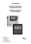
The iUPS101 is only permitted to be mounted in a vertical orientation.
The system weighs approximately 90Kg, so suitable lifting equipment and safety
provisions must be taken to ensure safe installation.
Correct Vertical Installation:
Fig 3.
Important!
The information shown on the ATEX rating plate is in relation to the
safety of the equipment. The functional operating parameters of the
system may vary slightly. Please see section 7 for details
9
Operating Manual
3.2 Fitting the Cables
Warning!
3.2.1
Installation to be by skilled electricians and instructed personnel in
accordance with national legislation, including the relevant standards
and, where applicable, in accordance with IEC 79.17 on electrical
apparatus for explosive atmospheres.
Grid-connected emergency systems
The UPS can be used as an emergency system, also known as an uninterruptible
power supply (UPS) – enabling a reliable supply to a site connected to an unreliable
network. In the event of an interruption to the energy supply from the public grid, the
UPS, connected to a battery, substitutes the faulty source and enables a support
supply to the users connected downstream.
These will be supplied as long as the energy stored in the battery allows. The battery
will quickly be recharged at the next reconnection to the public grid.
The AC input to the iUPS101 unit must be powered via an external site circuit
breaker/switch to allow disconnection of the power. This should be located close to
the unit and be suitably marked to identify it as the isolating device for the iUPS101
unit.
The use of the UPS must be carried out by qualified personnel who have been
checked by the responsible local authorities. The applicable local standards and
regulations must be adhered to.
3.2.2
Distributed Minigrid
The implementation of the UPS on top of a distributed minigrid requires special care
in choosing the distribution system. A TT distribution is recommended for the DC grid
as well as for the AC grid.
Warning!
3.2.3
The IT system (Power distribution system which is isolated from earth) is
not recommended for the distribution. This distribution is generally
forbidden by local laws
Earthing system
The UPS is a protection class I unit, which is intended for cabling in a grid type TT,
TN-S or TNCS. The earthing of the neutral conductor *(E) is carried out at a sole
installation point, upstream of the RCD circuit breaker *(D).
*(E) Earth-neutral connection bridge:
The neutral is earthed at a single point of the installation, downstream of the source
and upstream of the protection device(s) at the default current (DDR). When several
sources are available, each source must have an earthed neutral. If the source has to
be retained with an isolated earthling system (IT) the applicable local provisions and
regulations must be applied.
*(D) Differential circuit breaker:
A protection device must be installed downstream of the source according to the local
requirements and in compliance with the applicable regulations and standards.
10
Operating Manual
The UPS can be operated with any earthing system. In all cases it is imperative that
the protective earth be connected in compliance with the applicable standards and
regulations. The installer is responsible for the conformity of the installation with the
applicable local standards.
3.2.4
Mobile installation or installation connected to the grid via plug connector
When the input of the device is connected directly to the grid via a plug, the length of
the cable must not exceed 2 m and the plug must remain accessible.
In the absence of voltage at the input, the neutral and live are interrupted, thereby
guaranteeing complete isolation and protection of the cabling upstream of the UPS.
The earthing system downstream of the UPS is determined by the upstream earthing
system when the grid is present. In the absence of the grid, the earthing system
downstream of the inverter is in isolated mode. The safety of the installation is
guaranteed by the equipotential bonding.
Warning!
The connection (link) between the neutrals *(C) upstream and
downstream of the UPS is not permitted in this configuration.
*(C) Connection of the neutrals:
In a fixed installation where the neutral is connected to the earth at a single
installation point upstream of the UPS, it is permissible to carry out a connection of
the neutrals in order to preserve an unchanged earthing system downstream,
independent of the operating mode of the UPS. This choice shows the advantage of
keeping the differential protection devices downstream of the UPS.
This connection (C) is not permitted if a socket is installed upstream of the UPS.
This connection type guarantees the optimal continuity for supplying the UPS loads.
The first isolation fault will not lead to an interruption in the supply. If the installation
requires the use of a permanent isolation controller this would have to be deactivated
when the TT network is present at the UPS input.
Warning!
3.2.5
All sockets and protection class I devices connected downstream of the
UPS must be properly connected to the earth (earthed socket). The
cabling rules above remain valid, including fixed installations, in all
cases where the UPS input is connected to the grid via a plug connector.
Fixed Installation
The installation may be equivalent to a mobile installation (with interrupted neutral). In
a fixed installation where the neutral is connected to the earth at a single installation
point upstream of the UPS, it is permissible to carry out a connection of the neutrals
in order to preserve an unchanged earthing system downstream, independent of the
operating mode of the UPS. This choice has the advantage of keeping the protection
devices downstream of the UPS. This connection can be carried out by modifying the
configuration using the control panel.
In this case the appearance of the first fault will lead to the installation stopping or the
disconnection of the protection devices upstream and/or downstream of the UPS.
Safety is guaranteed by the equipotential bonding and by any RCD circuit-breakers
placed downstream.
This connection (C) is not permitted if a socket is installed upstream of the UPS.
11
Operating Manual
3.2.6
Installation with automatic PE-neutral switching
In certain applications, it is desirable to keep the neutral upstream and downstream
of the UPS separated (C) while re-establishing the earthing system (TN-S, TT or
TNC-S) in the absence of voltage at the input. This can be programmed by the
configuration via the control panel. This modification must be carried out possessing
technical knowledge, at the responsibility of the installer and in conformity with the
applicable regulations and standards.
3.2.7
Connecting the cables
IMPORTANT!
All cables should be connected to the iUPS101 via the correct
cable gland and fitted by a competent person.
IMPORTANT!
Changes in the design and modifications to the equipment are not
permitted. If any changes are performed on the enclosure the
ATEX certification will become void.
Important
The installer MUST ensure that all cables have adequate
mechanical protection to avoid damage to the wires.
IMPORTANT!
Users must read the Installation and maintenance instructions
supplied for the iSTB Enclosure assembly before terminating any
cables. (Included in Chapter 10 for reference)
Remove the cover from the Ex ‘e’ Terminal box and fit the cables in the correct
positions shown below for your product:
12
Operating Manual
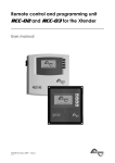
3.2.8
24V Cable Termination:
Auxiliary
Outputs +
Can Bus
See fig 3.5
X = Not connected
X
X
L1
N1
E
AC
IN
X
X
X
X
X
L2 N2 E
X
+
BATT
24V
AC
OUT
Fig 3.2
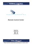
3.2.9
48V Cable Termination:
Auxiliary
Outputs +
Can Bus
See fig 3.5
X = Not connected
X
X
L1
N1
AC
IN
E
X
X
X
X
L2 N2 E
-
+ - +
BATT BATT
24V
24V
AC
OUT
Fig 3.3
13
Operating Manual
3.2.10 Parallel AC Output Termination:
It is possible to parallel the AC outputs of up to 3 x iUPS101 systems together. A
maximum of 2 systems can be connected in the Ex ‘e’ terminal box to provide twice
the power – Contact Extronics before connecting systems in this manor. See
Fig 3.4
Auxiliary
Outputs +
Can Bus
See fig 3.5
X = Not connected
X
L1
N1 E
MAINS
AC IN
L2 N2 E
AC IN
Loopthrough
L3
N3
E
AC
OUT
Fig 3.4
3.2.11 Auxiliary Output & CANBUS:
Fig 3.5
14
+
BATT
24V
+
BATT
24V
Operating Manual
3.2.12 Emergency Shutdown Signal
This signal is disabled by default. You must enter the Ex’d’ enclosure to enable this
functionality. More detail on the configuration and behaviour of this signal can be
found in section 4 of this manual.
Emergency shutdown signal is a ‘hot’ 24-48Vdc signal provided by the user. Please
see fig 3.5 for details. The signal is not polarity dependant, and therefore can be the
wires can be inserted in either of the terminals shown in fig 3.5.
3.2.13 CAN bus connections
These are not required on standalone iUPS101 units. These connections are used
when multiple iUPS101 units are connected in a parallel configuration (as per 3.2.10)
with a common battery bank. This is a communication connection between the UPS’s
and is used to allow synchronisation of the AC outputs for parallel UPS’s. Failure to
provide this connection could lead to the system failing to power on or stoppage of
the UPS.
If you are connecting units in parallel, please ensure you have consulted Extronics to
advise that systems are to be connected in this manor, as correct termination of
CANBUS cabling is required internally to the Ex’d’ enclosures. Providing you are
happy your UPS has been configured for parallel operation, you can connect the
CAN wires between the UPS’s as shown in section 3.2.11
Please note connecting cable should be a 3x twisted pair connected in a 1:1 manor
between each UPS.
3.2.14 Connecting the AC supply sources
The UPS is intended to be supplied by alternative voltage sources such as the public
grid or a generator. Check that the rated voltage of the source corresponds to the
rated voltage of the UPS specified on the rating plate.
The source must be connected to the correct ‘Mains AC IN’ shown in the product
diagrams above with sufficient wire section at least equal to the max AC input current
shown in the table 3.0 below.
The AC input current ratings are higher than the output ratings as the system may be
supplying the load and recharging the batteries at the same time following a
discharge.
Important!
There is no circuit protection on the AC input to the UPS. Users should
provide adequate protection against overload by way of a suitable circuit
protection device such as a RCB / MCB or fuse that is correctly rated for
the system– see the table below.
15
Operating Manual
iUPS101 Max
Rated Power (VA)
Up to 3000
Up to 2500
Up to 2000
Up to 1000
230V System Max AC
input current (A)
27
24
21
16
120V System Max AC
input current (A)
50
44
39
28
Table 3.0
3.2.15 Connecting the AC output
High voltages may be present on the connection terminals. Make sure that
the inverter is deactivated and that there is no AC or DC voltage present on the AC
IN terminals and battery terminals, before proceeding with the connection.
The AC output connections must be wired with sufficient wire section at least equal to
the max AC output current of the Product shown in table 3.1 below:
iUPS101 Max
Rated Power (VA)
Up to 3000
Up to 2500
Up to 2000
Up to 1000
230V System Max AC
output current (A)
15
12
10
5
120V System Max AC
output current (A)
30
25
20
10
Table 3.1
3.2.16 Connecting the battery
IMPORTANT!
Before connecting the battery, carefully check the voltage and
polarity of the battery using a voltmeter. Incorrect polarity or
surge voltage may seriously damage the device.
IMPORTANT!
For systems with periods of inactivity, such as a long shutdown
or moving/storing a mobile system where the UPS is not in use
and there is no AC mains supply. Users should remove DC
supplies to the system when not in use.
The iUPS101 is designed to be used in association with the iBATT100 Zone 1 battery
enclosure. Terminate the battery cables to the appropriate connections shown in the
diagrams above.
16
Operating Manual
3.2.17 Wiring auxiliary contacts
These contacts are reversing contacts that are potential-free. The admissible
currents and voltages for these contacts are 12A: 250 VAC/24VDC or 3A: 50 VDC
max. The cabling of these auxiliary contacts depends solely on the application and
cannot be described in this manual. These auxiliary outputs are not intrinsically safe,
and if used, the cabling / connected equipment must be taken to a safe area.
For more information on configuring the auxiliary contacts, please see chapter 8 of
this manual.
3.3 Setting to work
Once all cables are connected correctly and inspected, refit the enclosure lid using
the four screws previously removed. Connect the battery cables within the battery
enclosure – consult iBATT100 operating manual.
Note!
Ensure the lid is secure, correct cable glands are fitted and the
unit device correctly wired and earthed for the particular
application before applying power
Note!
Ensure that the lid gasket is clean and undamaged before fitting
the lid.
17
Operating Manual
3.4 Fusing
All fuses for the system are supplied fitted and contained within the Ex ‘d’ enclosure
and protect against system faults or overload. Should the fuses blow or need to be
inspected, only a qualified person must open the Ex ‘d’ enclosure – see section 2.
Fig 3.5
3.4.1
Fuse Values
DC Battery protection fuse, F1 = 160A
AC output fuse, F3 See table 3.2
Output Power (kVA)
Up to 3000
Up to 2500
Up to 2000
Up to 1000
230V System Max AC
output current (A)
15
12
10
5
120V System Max AC
output current (A)
30
25
20
10
Table 3.2
Caution!
Only the fuse values listed in the table above may be fitted to the
iUPS101. Failure to fit the correct fuse will invalidate the ATEX
certificate. Fuses must not be replaced without further
investigation as to the cause of the failure. If in doubt, please
contact Extronics
18
Operating Manual
4 Description and Functioning
4.1 Circuit Diagram
4.2 Description of the main functions
4.2.1
Overview
The iUPS101 contains two major components which work completely independently
to each other to give a high performance industrial inverter charger with the additional
protection required for charging of batteries in hazardous areas. The first component
is the main UPS inverter charger as depicted in the circuit diagram above, and the
second component the Extronics bespoke design battery charge protection circuitry.
4.2.2
Inverter
The IUPS101 is equipped with a high-performance inverter which supplies a perfect
and very precise sine wave. Any unit designed for the 230 V/50 Hz electrical grid may
connect to it without any problem, up to the rated power out of your IUPS101. The
inverter is protected against overloads and short-circuits.
4.2.3
Battery protection circuit
This bespoke circuitry works completely independently to the UPS, providing a fault
tolerant battery charge protection required as per EN60079-7:2007 for charging of
batteries in a hazardous areas. Its function is to monitor the charging voltage and
current from the inverter / charger to ensure they do not exceed dangerous limits
advised by the battery manufacturer. In the event of battery charge failure the battery
protection circuit will ‘trip’ causing the connection between the UPS and the batteries
to be isolated and prevent any dangerous fault conditions transferring to the
batteries.
19
Operating Manual
4.2.4
Automatic load detection
In order to save battery energy, the IUPS101 inverter stops and automatically goes
into load search when the detected load is lower than the sensitivity set by the
configuration. It automatically goes back into operation when a power consumer
greater than this value demands it.
4.2.5
Transfer relay
The IUPS101 can be connected to an alternative power source such as a generator
or public network. When the voltage at the entry satisfies the voltage and frequency
parameters, the transfer relay will be activated after a delay. This delay may be
adjusted (extended) to allow a fully stable status of the generator before transfer.
When the transfer relay is activated, the voltage present at the input of the iUPS101
is available at the output for the consumers connected. At the same time the battery
charger goes into operation.
Important
When the transfer relay of the iUPS101 is active, the voltage at the output
of the IUPS101 is equivalent to that which is present at the input and
cannot be influenced or improved by the iUPS101. The consumers are
supplied by the source present at the “AC IN” input via the transfer relay.
The maximum current of the transfer relay is 50 A. The sharing of energy between
consumers and the battery charger is adjusted automatically. The transfer relay will
be deactivated when the input voltage no longer satisfies the voltage and frequency
requirements at the input or when the current limit is exceeded. If the exceeding of
this limit is prohibited, the UPS passes immediately into inverter mode. In this case
the loads are supplied exclusively by the battery via the inverter. This switching
always takes place automatically. The presence of increased dynamic loads (such as
pneumatic angle grinders, etc.) may lead to an undesirable opening of the transfer
relay due to the weakness of the source. To this case, a delay in the opening of the
transfer relay can be adjusted. The transfer normally takes place without any
interruption when the generator stops. It would typically be 40 ms in the event of the
immediate loss of input voltage at “AC IN”.
4.2.6
Fast voltage loss detection mode (fast transfer):
When the iUPS101 is connected to the public grid or to a generator supplying stable
and clean AC voltage, a fast voltage loss detection mode can be used. In this mode,
perturbation or lack of voltage of less than 1 millisecond can be detected, switching
the unit in inverter mode immediately.
The sensitivity of this detection is adjustable. This mode guarantees a zero or
maximum of 15 ms transfer time, and should not be used in presence of highly
disturbed utility grid or with a low power generator or a generator supplying a poor
quality voltage.
20
Operating Manual
4.2.7
Battery charger
The battery charger for the iUPS101 is completely automatic and is designed in such
a way as to guarantee an optimum charge for the lead-acid batteries. Once the
transfer relay is activated, the battery charger goes into operation.
The battery charger is designed in such a way as to guarantee charging of the
battery that is as complete as possible. The charging process is at four levels by
default and guarantees optimum charging of the batteries. The charging current
should not be adjusted from the supplied settings.
Important!
In its default configuration the iUPS101 does not use constant current
charging.
Important!
Alternative charge profiles can be set up by Extronics for the charging of
NiCd batteries in accordance with battery manufacturers operating
instructions.
4.2.8
The inverter as source backup (“smart boost” function)
The UPS contains a smart boost function where the batteries can provide additional
power to that of the source to increase the available output power; however this must
remain disabled as this will cause the system to operate outside of its rated output
power, and therefore invalidate the safety parameters of the ATEX certificate.
4.2.9
Battery protection
The battery is protected against deep discharge. When the battery has reached the
low voltage disconnection threshold the inverter will stop. The inverter will restart
automatically when the battery voltage has reached the restarting threshold.
This restarting threshold can be automatically readjusted if set to do so, in order to
better protect the battery against repeated cycling in an "almost empty" state of
charge. The restarting threshold is then incremented up to a maximum value,
whenever the LVD (low voltage disconnection) is reached.
If the inverter is repeatedly encountering a low voltage disconnection in a short
period, it will stop permanently and will only start again via an operator’s restart.
When the inverter has stopped permanently and there is no AC input supply, there
will be a natural discharge of the connected batteries by the iUPS101 and internal
battery safety monitoring circuitry.
In order to prevent situations which may cause the UPS to continually draw power
from the batteries, a deep discharge protection module is included. In the event that
there is no AC input voltage present on the iUPS101 for a period of 24hrs, the deep
discharge protection module will disconnect the batteries from the inverter by
deliberately ‘tripping’ the battery protection circuitry. This will cause the battery
isolation relays to open and the system will shut down; requiring the user to reset the
system to power the UPS back on.
21
Operating Manual
IMPORTANT!
For systems with periods of inactivity, such as a long shutdown
or moving/storing a mobile system where the UPS is not in use
and there is no AC mains supply. Users should remove the
incoming AC and DC supplies to the system when not in use.
WARNING!
If the batteries are to be disconnected in a hazardous area, then
an appropriately certified means of isolation must be provided.
WARNING!
All parts of the enclosure must never be opened while energised,
or when an explosive gas atmosphere is present.
4.2.10
iUPS101 protection
The IUPS101 is protected electronically against overloads, short-circuit, overheating
and reverse current (cabling of a voltage source on AC out).
In the event of overload or short-circuit at the output, the inverter stops for some
seconds and restarts. If the inverter is repeatedly encountering this situation in a
short period, it will stop permanently and will only start again via an operator’s
manual control.
If the battery voltage exceeds the programmed value the inverter stops and starts up
again when the voltage is less than the set level. If the iUPS101 is repeatedly
encountering this situation in a short period, it will stop permanently and will only start
up again via an operator’s control.
Important:
4.2.11
Overheating of the UPS due to operation in increased ambient
temperature or rated loads above those specified for your product may
lead to overheating of certain internal components of the unit. In this
case, the device will automatically limit its power output as long as this
abnormal situation persists.
The IUPS101 is protected from reverse polarity by means of a fuse
installed within the Ex ‘d’ enclosure.
Auxiliary contacts
The iUPS101 has two dry reversing contacts that are potential-free. The status of the
contacts in idle mode (deactivated) is indicated by the annotations, N.C. = normally closed
and N.O. = normally open.
Maximum contact loads: 230 Vac / 24 Vdc: 16 A or: max. 50Vdc/ 3A
These dry contacts are programmed by default for the following functions:
Contact no. 1 (AUX 1): The contact has a function of automatic start of generator (two wires).
The contact will be activated when the battery voltage is below a set value, during a given
time. The contact will be deactivated when the charge cycle as reached floating, or when the
Aux. 1 deactivation voltage is reached.
Contact no. 2 (AUX2): Alarm contact by default. It is deactivated when the inverter is out of
service or is working at reduced performance, either because of manual control or if there is
an operational fault such as overload, under-voltage of the battery, over-temperature, etc.
The functions of the two auxiliary contracts can be modified and programmed variously –
contact Extronics for details
22
Operating Manual
If the operator or installer requires different behaviour for the auxiliary contacts, they are both
freely and individually programmable depending on the battery voltage and the inverter
status and the internal clock. The intelligent programming of the auxiliary contacts allows
many applications to be considered such as:
Automatic start-up of the generator (two or three wires)
Automatic load shedding of the inverter (2 sequences)
Global or individual alarm
Automatic disconnection (load shedding) of the source
4.2.12
Remote Emergency Disconnect
Note: This is a comprehensive signal and leads to the stoppage of the
iUPS101
Important:
This function is disabled by default, and can only activated by the
removal of Jumper links LK2 and LK3 on the battery protection PCB
contained within the Ex’d’ enclosure of the iUPS101. See Fig 4.1 below
for location of the jumper links.
23
Operating Manual
The remote emergency disconnect allows users to deliberately ‘trip’ the battery
protection circuitry, which will disconnect the batteries from the UPS and shuts the
system down. This should only be done in the event of an emergency that requires
the AC supply to the load to be removed. The remote emergency disconnect signal is
a ‘hot’ 24-48Vdc supply provided by the user. If the remote emergency disconnect
function is enabled, failure to provide this signal will prevent the iUPS101 from
powering on. Similarly, removal of the signal will cause full system shut down and
loss of supply to the connected load. Details for the connection of this signal can be
found in section 3 of the manual.
24
Operating Manual
5 Operation
5.1.1
Powering up the installation
The power up of the iUPS101 must be carried out in the order given below. Any
power off must be carried out in the reverse order.
Initially, the display will be blank. Press the reset button on the front panel (See Fig
4.0) - this will close the contactors within the UPS, and connect the batteries. The
green ‘battery healthy’ lamp should illuminate, and the display should come on. You
can now power on the AC input to the UPS.
5.1.2
Activating and deactivating the iUPS101
When one of the displays is visible, it is possible to activate or deactivate the
IUPS101. To do this, simply press the key ESC. The key request on the screen
indicates whether you are going to activate or deactivate the unit.
Once the key has been pressed, you must confirm
your choice by using the key YES. If you do not want
the action to be carried out, it can be cancelled by
pressing the NO key.
Note: This is a comprehensive signal and leads to the stoppage or starting of
all iUPS101s connected to the remote control.
Battery
Healthy
Fig 4.0
25
Operating Manual
There is no need to configure any settings for charge voltage and current, as these
are already programmed into the iUPS101 by Extronics, depending on the battery
configuration and rated load.
Warning!
At no point should the battery charge current be altered without
consulting Extronics
During normal operation, the Battery healthy lamp should remain illuminated. If this
extinguishes at any point, this indicates the connection between the UPS and the
batteries has been interrupted either for safety reasons, or there is a fault with the
system.
5.1.3
Status Information
The display shows charging and load information during normal operation. See Fig
4.1
Fig 4.1
A- Shows Information on the AC Input
B- Shows Information on the AC Output
C- Shows Information on the battery
The display will also show information on a fault should one occur.
There is an Expert user level for advanced programming and configuration of the
UPS and auxiliary contacts. See the advanced programming section in this manual.
26
Operating Manual
5.1.4
Basic displays
When the remote control is connected to an IUPS101, it is possible to access to
different display menus divided into distinct categories.
Information on the system
Real time information displays on the operating
mode of the installation
Informatio
The history of events occurring in the installation
Adjustment of RCC remote control options
Settings
Adjustment of configurations on the IUPS101(s)
The settings of the BSP
(Only if a BSP is present)
The settings of the MPPT
(Only if a MPPT is present)
To go from one display to the other, use the keys UP and DOWN on the front of the
system.
To visualize or modify the options of one of the basic displays, press the key SET
when this one is displayed.
27
Operating Manual
Depending on the components connected to your system, it is possible that
other displays complete this series.
In the case of a system in 3-phase or in parallel, the following displays are available
too:
Real time display of information on the state of
running of the installation
28
Operating Manual
6 Advanced Programming
The iUPS101 visual display, and Ex’d’ buttons give you access to a many settings
and possibilities. However, it is important that user understands that this
programming should only be performed by a competent engineer, as changes can be
made that will impair the safety of the system. In most cases the only parameters that
will need setting are the Auxiliary alarm contacts.
6.1 Adaptation to the source
These values have been programmed by Extronics, and do not need to be altered.
6.2 Adaptation to the battery
Charge current {1138}
This has been programmed by Extronics to suit the batteries supplied with your
system, and should not be changed under any circumstances.
6.3 Activation of the function Smart-Boost
This function has been disabled by Extronics and should not be activated under any
circumstances. Failure to comply with this could impair the safety of the system and
allow the maximum output power to exceed its rated value.
6.4 Adjusting the AC Output Frequency {1112}
This setting allows you to alter the output frequency of the inverter of the iUPS101.
This setting changes the limit frequencies on the charger's synchronization.
29
Operating Manual
6.5 Setting of the RCC remote control
This screen gives you access to the remote control
basic settings. From one of the basic menu items,
use the keys UP and DOWN until reaching the item
“Adjustment of the remote control”, then confirm by
using the key SET.
When the item to be modified appears on the screen, press the key SET to be
able to modify it. This value then displays in inverse video. Now use the keys
UP and DOWN to modify it. Once the correct value has been obtained, confirm
by using the SET key or exit without modifying by using the key ESC.
Each configuration has a unique ID displayed top right (see example below)
these numbers are indicated between curly brackets in this manual : {xxxx}
EXAMPLE to modify the current date
Go to the following screen using the UP and DOWN
keys.
Press the key SET to access the remote control
adjustment.
Go to the following screen using the key DOWN.
Press the key SET to modify the configuration
Set the correct date using the keys UP and DOWN
Go to the adjustment of the month using the key SET
Also set the month using the keys UP and DOWN
To complete, go to the year adjustment using the key
SET
After having adjusted the year using the keys UP
and DOWN, confirm using the key SET.
6.6 Setting of the language {5000}
The default language is English and the IUPS101 can store up to four languages
simultaneously. This configuration allows you to choose one of them.
6.7 Setting of time {5001} and date {5002}
The IUPS101 has a perpetual calendar and an internal clock powered by a backup
battery. The correct adjustment of the date and time allows accurate recording of
events occurring in the installation as well as correct use of time-related functions,
e.g. the disabling of the auxiliary relays during the night.
30
Operating Manual
6.8 User level {5012}
The setting of the user level allows you to choose the access to the IUPS101
according to your level of expertise.
The INFO ONLY level may be selected by entering the code:
460081
This level does not allow the IUPS101 configurations to be modified; it only allows
information to be displayed on the system.
Use the INFO ONLY level after adjusting the configurations if the remote
control is located in a public place or if it is accessible by people who are not
authorized to carry out adjustments on your system.
You may change the level at any time to make new adjustments, by entering
the appropriate code.
The BASIC level allows you to configure basic IUPS101 functions, limiting the field of
actions to simple configurations. Please note that the incorrect adjustment of basic
configurations may lead to the malfunctioning of the installation. This level is selected
by default. To return to this level after a change, enter code:
943274
The EXPERT level allows access to more complex IUPS101 configurations and this
level of usage may only be used with extensive specialist knowledge. To access the
expert level, enter code:
426468
6.9 Drive the remote control to the user level basic {5019}
You can with this option bring the remote control back to the level “user Basic”.
31
Operating Manual
6.10 Information on the operating mode of the installation
There are two different views for displaying information on the system: a simplified
and a configurable display. When one of these two displays is visible, it is possible to
activate or deactivate the system. For further information, please refer to the
paragraph on activating and deactivating the combi IUPS101.
The simplified display only indicates the current time
and the mode of the IUPS101 (ON or OFF)
The configurable display shows the system in its entirety, represented by a synopsis
of distinct information blocks.
A
B
C
D
E
F
Information on the battery
Information on the grid input
Information on the grid output
Information on the auxiliary contacts
Information on the transfer and output relays
Information on the state of the maximum current of the source (Input limit) (L) and of
the Smart-Boost (B: Boost activated, L: input limited)
G Information on possible locking of the function (G)
Two pieces of information related to blocks A, B and C may be viewed
simultaneously. To change displayed information, proceed as follows:
Press the key SET (one of the pieces of information
is displayed in reverse video).
Go to the value to be changed by using the UP and
DOWN keys.
Enter into modification by using the key SET. You
may now view the values that can be displayed in
this area.
Using the keys UP and DOWN, select the new
information that you want to see appearing.
32
Operating Manual
Confirm your selection by using the key SET.
To escape at any time, use the key ESC to return to the starting display.
The following information is available:
With regard to the grid input
AC In input voltage
AC In input current
AC In input power
Input frequency
The value of the source max current (Input limit)
Energy from AC-In of the previous day
Energy from AC-In of the current day
With regard to the grid output
Output voltage
Output current
Output power
Output frequency
Consumers energy of the previous day
Consumers energy of the of the current day
With regard to the battery
Battery voltage
Actual charge current of the batteries
Programmed charge current
Ripple voltage of the batteries
Charging phase (bulk charge, absorption, float charge, etc.)
Dynamic compensation of the battery (compensation of the thresholds due to the internal
resistance of the battery)
Operating mode (inverter, charger, etc.)
Battery temperature (if a sensor is present)
The battery temperature’s inherent compensation (if a sensor is present)
Discharge of battery of the previous day
Discharge of battery of the current day
Remaining time of the phase of absorption, equalization or reduced absorption
State Of Charge of the battery (SOC) (if a BSP is présent in the system)
If a piece of information is not available, the screen displays - - - -.
Information on the auxiliary relays as well as the output and transfer relays appears
as open or closed in the synopsis according to their current state.
Auxiliary relays are indicated with their corresponding number as well as the letter A
if they are operating in automatic mode and M if they are controlled manually.
Other letters may be displayed with regard to specific programming. Please refer to
the corresponding chapter.
The general operating mode of the combi IUPS101 is displayed in large letters on the
two visualisation screens (ON or OFF).
33
Operating Manual
6.11 Display of the parallel and three-phase systems
While using several IUPS101s in parallel or in three-phase, an additional view is
available. This view summarizes the various electrical values of the system. Like for
the display of a system with one single IUPS101, you can access to the displayed
values in order to modify them.
Each summarized view gives access to the display
of one IUPS101.
In the view of the three-phase, you have access to
the detail of one phase by pushing the key SET and
then, by pushing UP or DOWN, you can choose the
phase you want to see displayed in details.
If the phase consists of several IUPS101s in parallel
or if the system is a single phase one but with
several IUPS101s in parallel, you can then have
access to the display of each IUPS101 by selecting
in the view parallel one of the three available
inverters.
34
Operating Manual
7 Messages and account of events
This screen allows you to view the various events
that have occurred in the installation.
The events that occur in your installation are displayed on the remote control screen.
The events are classified within two categories:
The events that may have serious consequences are displayed up to the moment
where the user confirms that he has taken note of them by pressing on an RCC
remote control key. These events are recorded in the event history and may be
consulted subsequently.
Events not posing a risk are indicated briefly on the display and then disappear.
Some are recorded in the event history.
On the other hand, the messages may have different origins and they are preceded
by an attribute to enable you to understand the importance:
Message: normal event but one that conditions or influences the operation of the
IUPS101.
Error: an event that prevents the correct or normal operation of the IUPS101.
Alarm: an event that may cause a malfunction of the installation if it is not corrected.
Stop: The system had to be stopped as a major event is preventing its operation.
Caution, a stop can be temporary and the system can restart automatically.
In case of work on the installation, switch off the system.
INSTALLER - In the message history, you may clear the list of saved messages. The
clear function is signalled by ‘CLR’, opposite the SET button. You must confirm to
clear the list of messages.
Use this function, for example, after maintenance visit or when completing
the commissioning of the installation.
7.1
(000) Alarm: Low battery voltage
The battery is almost completely discharged. If the situation persists, the inverter
function of the IUPS101 will be deactivated.
Solution:
•
•
•
recharge your battery as soon as possible
recharge your battery more frequently
increase the power or the energy available for the load (for instance with more solar
panels)
This message is generated in conjunction with the undervoltage of the
battery configuration {1108}.
The service life of the batteries is greatly conditioned by their state of charge.
Prolonged or repeated operation at a low charge may cause damage.
With the Smart-Boost function activated, it is also possible to discharge the
batteries even if connected to a source of energy.
35
Operating Manual
7.2 (003) Message: AC IN synchronization in progress
A valid voltage has been detected on the AC IN input and the IUPS101 is
synchronizing. Once synchronized, the consumers will be transferred to it and the
battery will be charged.
Note: It is possible to prohibit the transfer or the battery charging.
7.3 (004) Message: Wrong AC-In input frequency
The voltage at AC IN does not have a frequency included in the admissible range for
the IUPS101.
Solution: When operating on a generator, check its speed.
If you are not equiped to measure the generator frequency, measure its
voltage with no load. Indeed, if the voltage is correct, the frequency is
generally correct as well.
7.4 (006) Message: Too high AC-In input voltage
The voltage at the AC IN is too high for the IUPS101 and represents a danger for the
consumers; the transfer relay is not activated.
Solution: Reduce the voltage on the AC IN input to come into an admissible range.
7.5 (007) Message: Too low AC-In input voltage
The voltage at AC IN is too low for the IUPS101. The transfer of consumers and
battery charging are not activated.
Solution: Reduce the voltage on the AC IN input to come into an admissible range.
Do not increase the voltage of the generator during the battery charging or
when the consumers are connected to it: If the consumers stop, an
overvoltage may arise which will destroy components of your installation.
If the transfer of the consumers is carried out and the message appears
some seconds after the start of the battery charging, check that you have not
adjusted the charging voltage of the batteries too high in relation to your
source.
Also check the adjustment of the maximum current of the source (Input limit)
configuration {1107}.
7.6 (008) Stop: Overload inverter SC
The consumers require more power than the IUPS101 inverter can supply.
Solution:
•
•
Adapt the maximum power output of your consumers to the maximum power output
of the IUPS101
. Check that the cabling is not short-circuited.
36
Operating Manual
7.7 (014) Stop: Overtemperature EL
The IUPS101 stops due to overheating.
Solution:
•
•
•
Check that the ventilation holes of the IUPS101 are not obstructed.
Check that the IUPS101 is not situated in a place where the ambient temperature is
too high.
Adapt the power max. of the users to the nominal power of the IUPS101 according to
the ambient temperature.
The over temperature is disadvantageous for the service life of certain
electronic components. If the stoppages due to over temperature happen
frequently, corrective measures will be required.
7.8 (015) Stop: Overload inverter BL
The users need more power than the IUPS101 inverter can supply.
Method:
•
adapt the power max. of the users to the power max. of the IUPS101.
7.9 (016) Alarm: Ventilation fault detected
A dysfunction of the ventilation has been detected; get it checked by a technical staff.
7.10 (018) Alarm: Excessive battery ondulation
The voltage ripple at the battery cables is too high.
Solution:
•
•
•
•
Check that the battery cable section is correct.
Check the tightness of the battery cables.
Check that the charge current matches your battery.
Check the state of your batteries.
The use of batteries of an inappropriate capacity may also cause this error
message. In this case, reduce the charge current or lower the power output
of the consumers.
The voltage ripple on the batteries may be caused by their ageing. In this
case, lower the charge current.
7.11 (019) Stop: Too low battery voltage
The functions inverter and Smart-Boost of the IUPS101 are deactivated because the
batteries are discharged.
Method: recharge your batteries to reactivate these functions automatically.
7.12 (020) Stop: high battery voltage
The voltage of the battery at the IUPS101 DC input is too high. The system is
stopped for security reasons.
Method: check that the battery nominal voltage suits the IUPS101 one.
37
Operating Manual
In case of an external charger, check that it charges the batteries with a voltage
suitable for the IUPS101.
7.13 (021) Message: Maximum Current of the source (Input limit)
exceeded; transfer prohibited
The power output of the consumers exceeds the one specified for the source, and
the transfer relay cannot be activated. The IUPS101 operates in inverter mode.
•
•
•
This situation occurs only if you have deactivated the parameter {1436} Solution:
Check that the configuration of the maximum current for the source {1107}
corresponds to the maximum current of the source connected at AC In.
Reduce the number or power output of the consumers.
In this case, the transfer relay is not activated and the recharging of the
batteries cannot take place. If this situation continues, you might discharge
your batteries.
7.14 (022) Error: Voltage at AC Out
An unwanted voltage is present at AC Out.
Solution:
•
•
•
. check that you have not reversed the cabling of AC input and output.
. no source must be connected to the IUPS101 output (AC-Out).
. check the cabling of the installation.
7.15 (023) Error: Phase not defined
The jumper of phase selection (L1, L2 ou L3) is missing on the IUPS101.
The IUPS101 cannot operate without the phase being defined.
Solution: Check the phase definition jumper in the cable connection zone.
Refer to the IUPS101 manual for more information.
7.16 (024) Message: Control the battery of the clock
The maintenance battery is discharged. To avoid the clock goes back to zero in case
of a blackout, its replacement is necessary. Refer to the IUPS101 manual for this
replacement.
7.17 (041) Alarm: Overtemperature TR
The temperature of the IUPS101 is excessive and the output power is limited.
This message can also occur after a long operation in a too hot environment.
7.18 (042) Stop: Source at the output
A source of energy has been detected at the AC-Out output and supplies current to
the IUPS101.
Method: check that you do not have a source of energy connected to the output.
38
Operating Manual
If it is wished to have a supply on the output side (back-feeding) adapt the
parameter {1438}. Only the sources meant for such feeding and
synchronized can be used.
For an operation with a grid feeding inverter the load of this inverter can also
be controlled, see parameters {1438}, {1536} and {1549}.
In no case will the feeding source power be bigger than the IUPS101 power.
7.19 (058) Error: Lost of synchro master
A communication problem between the IUPS101s is detected.
Method: check the cabling in betwen the IUPS101s.
7.20 (059) Stop: Overload inverter HW
See code (015)
7.21 (060) (061) Alarm: Maximum duration security for auxiliary
contact
The maximum duration that you have selected for the relay activation with the
parameter {1514}, {1515} is reached and the activation conditions are still present.
The contact will not be reactivated as long as the conditions are present. Therefore
there is a risk that the auxiliary contact remains locked in this position unless you
reset this alarm.
Method: reset manually this alarm with the corresponding parameter ({1512}AUX1,
{1513}AUX2) by deactivating and then activating it.
Use this function with care and only as a security.
7.22 (062) Alarm: Genset problem, no AC-In after a start by means
of the auxiliary contact
The genset start has been driven by the auxiliary contact but there is no voltage at
the IUPS101 input.
Method: check that the genset runs and that its connection to the IUPS101 has not
been interrupted.
7.23 Stored events
Events are stored in the remote control. Any system not permanently connected to a
remote control does not store the events.
39
Operating Manual
To access the event history via one of the basic
displays, change the screen by using the keys UP
and DOWN until the “event history” screen
appears and then validate using the key SET.
The number shown at the top right indicates the
message number. In a system with several
IUPS101s, the events are presented in
chronological order and the lower line indicates
the IUPS101 to which the event refers.
Each event is recorded as well as the date and
time of its occurrence. The keys UP and DOWN
allow you to view all the events that have
occurred.
Where there is a system with multiple IUPS101s,
each message also contains the number of the
IUPS101 that has generated the message.
Quit the message display by using the key ESC
7.24 Utilisation and access levels
The functions described below refer to the EXPERT level. Depending on the user
level selected, access to all the functions may not be possible. Refer to the chapter
on setting the user level of the remote control for more information on this subject.
7.25 Pre-defined functions of the auxiliary relays
The two auxiliary relays (dry contacts) of the inverter-charger IUPS101 are already
programmed with factory settings and can be activated with various functions. They
react to different signals.
The factory settings depend on the IUPS101 models.
For more information on the auxiliary contacts pre-set functions, please see the
inverter-charger IUPS101 manual.
Caution, if your installer or supplier has done pre-settings, these pre-set
functions may have been changed.
7.26 Access to the parameters
You can access to the parameters by two different
ways:
•
•
By its parameter number;
Via the the main menu.
40
Operating Manual
7.26.1 Access to a parameter by its number
Each IUPS101 parameter is directly accessible by its unique reference number. This
function can be used in order to change the value of a parameter or to consult its set
value.
If you know the reference number of a parameter that you want to change, you can
access to it directly with this menu. Move with the keys UP and DOWN to highlight
the parameter then select it by the key SET. You have then the possibility to change
the value of this parameter.
For each parameter, its set value is written opposite to it. If a parameter does not
have a value displayed, this means that you do not have the user level required to
change the value or that the parameter does not have a value (a menu title for
instance).
When you want to access to a parameter which access level is superior to yours, it is
possible to do it only with a code: select the parameter that you want to change with
the keys UP and DOWN then press the key SET. The remote control then displays a
4 digits number. By communicating this number to your installer, you can receive an
activation number which will allow to modify the wanted parameter.
The key received is valid only for one single access to the wanted parameter. This is
why it can be necessary to be online with your installer when it comes to do several
changes.
7.26.2 Access to a parameter via the menu
The IUPS101 configurations are divided into several categories:
•
•
•
•
•
•
•
•
•
•
Basic configurations
Battery and its charge cycle configurations
Inverter configurations
The parameters of charger and input signals
First auxiliary contact configurations
Second auxiliary contact configurations
Auxiliary contact extended function configurations
The parameters of the system
Three-phase or parallel operation configurations
The parameters of grid feeding
According to the user level selected, it is possible to
access several hundred configurations. For this
reason, each configuration has a unique ID
displayed top right. In the event of questions on the
subject of a configuration, ensure that you have this
number at hand.
When you modify a configuration, a star is displayed
to the left of the value if it corresponds to the factoryset value.
The various configurations can be adjusted within a large range. Nevertheless, some
configurations are interdependent and cannot be adjusted beyond the value of other
configurations. You can consult the list of dependencies on the list in appendix 1.
41
Operating Manual
8 Configuration for auxiliary contacts 1 and 2
{1201} {1310}
The IUPS101 inverter/charger is equipped with two auxiliary relays each with one
free of potential contact (reverser). These two relays allow multiple functions to be
carried out by using adequate cabling as well as simple programming.
The programming of each contact is carried out independently except when
conditions require the use of two relays. In this case, the programmed events for
activating the second relay are automatically deactivated.
The extended functions of the auxiliary contacts are described at the end of the
chapter on simple functions.
The auxiliary contacts are activated immediately in response to the programmed
signals. When the activation conditions are no longer fulfilled, they are deactivated
with a delay of 2 seconds to avoid overswitching.
The auxiliary contacts respond to various signal types presented graphically below.
The following types of basic events may activate the contacts:
• Simple event
• Scheduled event
• Level
In the following description, each parameter has two reference numbers. The
reference on the left relates to auxiliary contact 1 and the reference on the right to
auxiliary contact 2 ({reference of the auxiliary contact 1} {reference of the auxiliary
contact2}).
The auxiliary contacts are factory set with pre-defined functions. If you wish to
implement a specific function you must clear the programming already set.
Use for that purpose the prarmeter {1569} or {1570}.
42
Operating Manual
8.1.1
8.1.1.1
Simple functions
Switching mode {1202} {1311}
The auxiliary contacts may be controlled in 4 different ways:
Manual ON: In this mode, the contact is permanently drawn whatever the external
conditions or programming
Manual OFF: In this mode, the contact is permanently released whatever the external
conditions or programming
Automatic: In this mode, the auxiliary contact is activated according to the conditions
and restrictions of its programming.
Reversed automatic: In this mode, the conditions and restrictions define the release
of the contact.
8.1.1.2
Combination of events mode {1497} {1498}
This configuration defines how the various events intended to activate the auxiliary
contact are combined.
Either a single event suffices to activate the contact (OR function) or it must have all
the active events in order for the contact to be activated (AND function).
43
Operating Manual
8.1.1.3
Temporal restrictions {1203} {1312}
These configurations allow the time frame to be defined in which the contact should
under no circumstances be activated. Three distinct schedules are accessible in the
form of restriction programs (programs 1 to 3). For each program, it is possible to
select the day of the week where the restriction is activated. If the day is selected it
appears on the screen and if it is not selected it is represented on the screen by two
horizontal lines.
Once the days are selected, it is necessary to adjust the time frame where the
restriction is active using the “starting time” and “finishing time” configurations. If the
finishing time is programmed before the starting time, the restriction time frame is not
taken into account. Below are the configurations with their references:
Program 1 {1204} {1313}
Days of the week {1205} {1314}
Starting time {1206} {1315}
Finishing time {1207} {1316}
Program 2 {1208} {1317}
Days of the week {1209} {1318}
Starting time {1210} {1319}
Finishing time {1211} {1320}
Program 3 {1212} {1321}
Days of the week {1213} {1322}
Starting time {1214} {1323}
Finishing time {1215} {1324}
INSTALLER - Program 4 {1216} {1325}
Days of the week {1217} {1326}
Starting time {1218} {1327}
Finishing time {1219} {1328}
Program 5 {1220} {1329}
Days of the week {1221} {1330}
Starting time {1222} {1331}
Finishing time {1223} {1332}
If your installer has made additional adjustments, it is possible that the
restrictions could be active even if they do not appear in one of the three
programs available to you.
8.1.1.4 Contacts activated with set schedules {1269} {1378}
The auxiliary contact can also be activated like a programmable clock. Three different
weekly programs are available.
For each program, the time frame may be applied to one or several days of the week.
If the finishing time is programmed before the starting time, the time frame is not
taken into account.
Program 1 {1270} {1379}
Days of the week {1271} {1380}
Time of start of activation {1272} {1381}
Time of end of activation {1273} {1382}
Program 2 {1274} {1383}
Days of the week {1275} {1384}
Time of start of activation {1276} {1385}
Time of end of activation {1277} {1386}
44
Operating Manual
Program 3 {1278} {1387}
Days of the week {1279} {1388}
Time of start of activation {1280} {1389}
Time of end of activation {1281} {1390}
8.1.1.5
Contacts activated by an event {1455} {1456}
The auxiliary contacts may be activated by the states or events occurring in the
installation. Each event may be combined with another to establish complex
functions.
8.1.1.5.1 IUPS101 OFF {1225} {1333}
The contact is activated if the IUPS101 inverter/charger is switched off, either
following a fault or manually.
8.1.1.5.2 IUPS101 ON {1518} {1519}
The auxiliary contact is activated if the IUPS101 inverter/charger is switched on.
8.1.1.5.3 Remote ON/OFF input active {1543} {1544}
The auxiliary contact is activated if the Remote ON/OFF input is active.
45
Operating Manual
8.1.1.5.4 Battery undervoltage alarm {1226} {1334}
If the undervoltage threshold is reached, this activates the contact. In contrast to the
acoustic alarm that is deactivated after a set time, this signal remains active as long
as the battery voltage is below the threshold. If the undervoltage fault cuts in, this
condition remains active as does the contact.
8.1.1.5.5 Battery overvoltage {1227} {1335}
Activates the contact in the event of battery overvoltage.
8.1.1.5.6 Inverter or smart boost overload {1228} {1336}
Activates the contact in the event of an error due to excessive power in the inverter or
the Smart Boost function. In the event that the inverter disconnects due to excess
power and it is attempting to restart, the contact is not activated until the end of the
attempts.
8.1.1.5.7 Overtemperature {1229} {1337}
Activates the contact in the event of overtemperature in the electronics or the
transformer.
8.1.1.5.8 No overtemperature alarm {1520} {1521}
Activates the auxiliary contact if no overtemperature alarm is active.
8.1.1.5.9 Active charger {1231} {1339}
Activates the auxiliary contact if the charger function is active. When the Smart-Boost
function is operating, the condition for activating the contact is not fulfilled.
8.1.1.5.10 Active inverter {1232} {1340}
Activates the auxiliary contact if the inverter function is active.
8.1.1.5.11 Smart-Boost active {1233} {1341}
Activates the auxiliary contact if the Smart-Boost function is active. For more
information on the smart boost function, refer to the manual for the IUPS101
inverter/charger.
8.1.1.5.12 AC In present with fault {1234} {1342}
Activates the auxiliary contact if there is voltage present at the AC In input but this
voltage does not fulfil the conditions for activating the transfer relay.
8.1.1.5.13 AC In present {1235} {1343}
Activates the auxiliary contact if a voltage is present at the AC In input. This condition
is independent of the state of the transfer relay.
8.1.1.5.14 Transfer relay drawn {1236} {1344}
Activates the auxiliary contact if the transfer relay is drawn.
46
Operating Manual
8.1.1.5.15 AC Out present {1237} {1345}
Activates the auxiliary contact if a voltage is present at the output of the IUPS101
inverter/charger.
8.1.1.5.16 Battery charging in bulk charge phase {1238} {1346}
Activate the auxiliary contact if the battery is in bulk charge phase.
8.1.1.5.17 Battery charging in absorption phase {1239} {1347}
Activates the auxiliary contact if the battery is in absorption phase. If the periodic
extended absorption function is activated, the contact is also activated in this phase.
8.1.1.5.18 Battery charging in equalization phase {1240} {1348}
Activates the auxiliary contact if the battery is in equalization phase.
8.1.1.5.19 Battery charging in floating phase {1242} {1350}
Activates the auxiliary contact if the battery is in maintenance phase. If the extended
reduced floating function is activated, the contact is also activated in this phase.
8.1.1.5.20 Battery charging in reduced floating phase {1243} {1351} and
8.1.1.5.21 Battery charging in periodic absorption phase {1244} {1352}
You can activate the auxiliary contacts on the reduced floating phase and the
periodic absorption phase.
8.1.1.5.22 Autonomy test in progress {1529} {1530}
This parameter allows you to activate the auxiliary relays if an autonomy test is in
progress. In that case, the relays are activated on the two types of test : monthly or
weekly.
8.1.1.6
Contacts activated by the battery voltage {1245} {1353}
These configurations allow activation of the auxiliary contacts if the battery voltage
passes below a selected voltage during a period that is configurable as well. Three
voltages linked to three durations are configurable to activate the auxiliary contact.
The auxiliary contact will only be activated after the battery exceeds again a certain
voltage value and also after a duration, both independently of the activation
parameters.
This voltage and this duration are programmable too.
•
•
•
•
•
•
•
•
•
•
•
•
•
Dynamic compensation of the thresholds {1288} {1354}
Voltage 1 active {1246} {1355}
Voltage 1 {1247} {1356}
Duration 1 {1248} {1357}
Voltage 2 active {1249} {1358}
Voltage 2 {1250} {1359}
Duration 2 {1251} {1360}
Voltage 3 active {1252} {1361}
Voltage 3 {1253} {1362}
Duration 3 {1254} {1363}
Voltage for deactivation of the auxiliary contact {1255} {1364}
Duration over battery voltage for deactivation {1256} {1365}
Deactivate if the battery is in floating mode {1516} {1517}
47
Operating Manual
8.1.1.6.1 Dynamic compensation of the thresholds {1288} {1354}
If the contacts are activated according to the battery voltage, you can use the voltage
dynamically compensated for each threshold.
If this function is not activated, the average battery voltage will be used.
If this function is activated, the real battery voltage is compensated according the
power used.
8.1.1.6.2 Deactivate if the battery is in floating mode {1516} {1517}
If you activate one of the auxiliary contacts according to the battery voltage, you can
force the deactivation if the battery is in floating mode. In this way, even if the
deactivation voltage is not reached or if the duration of the voltage deactivation is not
completed, the auxiliary contact will be released.
8.1.1.7
Contacts activated by inverter power or Smart-Boost {1257} {1366}
If the power output of the inverter exceeds a certain level, the contact may be
activated. The excess is linked to a duration. Three power levels linked to three
durations are configurable to activate the auxiliary contact.
The auxiliary contact will only be activated after the output power passes below a
value and over a duration, both independently of the activation configurations.
If the Smart-Boost function is active, these configurations are also taken into account
with the power of the boost.
•
•
•
•
•
•
•
•
•
•
•
Power 1 active {1258} {1367}
Power 1 {1259} {1368}
Duration 1 {1260} {1369}
Power 2 active {1261} {1370}
Power 2 {1262} {1371}
Duration 2 {1263} {1372}
Power 3 active {1264} {1373}
Power 3 {1265} {1374}
Duration 3 {1266} {1375}
Power for deactivation of the auxiliary contact {1267} {1376}
Duration below power for deactivation {1268} {1377}
8.1.1.8
Contacts activated according to the battery temperature {1503} {1504}
You can activate an auxiliary contact according to the battery temperature. This
function is available with the temperature sensor BTS-01 or with the battery monitor
BSP. Two distinct thresholds allow a switch on and off of the contact at different
temperatures.
•
•
•
Contact active with the battery temperature {1446} {1457}
Auxiliary contact activated below {1447} {1458}
Auxiliary contact deactivated below {1448} {1459}
8.1.1.9
Contacts activated on battery state of charge (SOC) {1501} {1502} (function active
only with a BSP)
You can activate the auxiliary contacts according to the battery state of charge. If the
battery state of charge goes below a given threshold, the contact will be activated. A
duration can be linked to the threshold, which means that the battery state of charge
must be below this threshold within the choosen duration, before the contact is
activated.
The contact is deactivated when the battery state of charge goes again below a
specific threshold that can be also linked to a duration.
The contact can also be deactivated when the battery reaches the floating phase.
48
Operating Manual
•
•
•
•
•
•
•
•
•
•
•
•
Level SOC 1 active {1439} {1442}
Level SOC 1 {1440} {1443}
Duration 1 {1581} {1590}
Level SOC 2 active {1582} {1591}
Level SOC 2 {1583} {1592}
Duration 2 {1584} {1593}
Level SOC 3 active {1585} {1594}
Level SOC 3 {1586} {1595}
Duration 3 {1587} {1596}
Level SOC to deactivate the auxiliary contact {1441} {1444}
Duration on level for deactivation {1588} {1597}
Deactivate if the battery is in floating phase {1589} {1598}
8.1.1.10 Security : Limit the time of activation {1512} {1513}
Caution :
If the maximum duration for the relay activation that you have selected is
reached and if the activation conditions are still present (for instance a
battery undervoltage), the contact will not be reactivated as long as the
conditions are present. Therefore there is a risk that the auxiliary contact
remains locked in this deactivated state and you will have to reset manually
this alarm by deactivating and then activating this parameter.
Use this function with care and only as a security.
8.1.1.11
Maximum duration of activation {1514} {1515}
When the conditions are met, either one or two relays are activated permanently. If
you wish that the activation duration is limited in time, even if the conditions are met,
you can activate this function. Once the relay is activated, a countdown runs
according to the duration you have selected. Once this countdown is completed the
relay is released, even if the conditions are still there. The relay can not be anymore
activated as long as the activation conditions have not disap-peared.
8.1.1.12 Reset all settings {1569} {1570}
This function serves to reset all previous settings done on the corresponding auxiliary
contact. Once this operation done, the auxiliary contact is not activated anymore.
Caution: this function cannot be cancelled.
Use this function before programming any function for an auxiliary contact.
By doing this way you are sure that you begin with no unexpected setting
who can activate the contact.
8.1.2 AUXILIARY CONTACTS 1 AND 2 EXTENDED FUNCT. {1489}
8.1.2.1
Generator startup
The two contacts may be combined in order to automatically start up a generator
equiped with an electric starter. In this case the two contacts are dedicated to this
function.
Auxiliary contact 1 serves as an operational contact and auxiliary contact 2 as a
startup contact.
49
Operating Manual
The startup condition of the generator
must be programmed with the
configurations of auxiliary contact 1. The
startup is carried out by first activating
the operational contact and then
activating the startup contact. The latter
engages several times, if necessary, to
start up the motor. If a voltage appears at
the terminals of AC In, the startup
contact is released.
A. Main contact hold/interrupt time
{1574}
B. Time before a starter pulse {1494}}
C. Starter pulse (with AUX2) {1492}
D. Number of starting attempts {1493}
8.1.2.1.1
Generator control {1491}
Activates the combination of the two auxiliary contacts for the generator start and the
management of the start impulses.
8.1.2.1.2 Number of starting attempts {1493}
The start contact is activated a limited number of times in order to protect the starter
if the generator has a fault. Once the maximum number of start has been reached,
the operational contact is also deactivated. For a new attempt to be made the
condition that generated the start must disappear and reappear.
8.1.2.1.3 Starter pulse (with AUX2) {1492}
With this configuration you can adjust the time at which the start contact is activated.
8.1.2.1.4 Time before a starter pulse {1494}
This configuration determines the duration between the start attempts. It also
determines the duration between the activation of the operational contact and the first
attempt at restarting.
8.1.2.1.5 Main contact hold/interrupt time {1574}
Some generators must have the main contact completely stopped between the
cranking attempts (choke pulse). This parameter allows to set this duration.
50
Operating Manual
9 Configuration of AC Transfer
9.1 Activate immediate detection of grid outage (UPS) {1435}
This parameter allows to starting the inverter mode as quick as possible in case of
fluctuations of the AC-In grid. This function is useful when it comes to very sensitive
loads that require an uninterruptible power supply (UPS). If this function is active,
being connected to a fluctuating source (weak grid or unstable generator) will lead to
a frequent switching between inverter and charger modes by opening and closing of
the transfer relay.
9.2 Tolerance on the immediate detection of a grid loss {1510}
When the immediate detection of a grid loss is activated, this parameter allows you to
increase or decrease the detection sensitivity. The higher the figure the weaker the
sensitivity.
9.3 Transfer AC-In for delayed transfer opening {1199}
This configuration determines the voltage below which the transfer relay will open
after a certain period of time. The UPS will then run in inverter mode.
9.4 Delay before passing to inverter {1198}
When the input voltage is below the transfer voltage to the inverter, the transfer relay
does not open immediately. With this configuration, the period during which the
transfer remains drawn can be specified. After this duration, the transfer relay is
opened and the inverter function is activated (if the function has not been blocked or
deactivated).
This delay is particularly useful on less stable grids or with generators with an output
voltage that varies considerably during the activation of heavy loads.
9.5 Immediate transfer AC-In voltage {1200}
Use the adjustment of this configuration to adjust the critical voltage for the operation
of equipment that must not experience interruptions. In the case of a fluctuating grid,
if its voltage passes below the value of the configuration this immediately activates
the inverter function, thereby ensuring supply to the consumers.
9.6 Frequency delta accepted above End {1505}
This setting allows you to determine the upper limit of the accepted frequency. This
value is added to parameter {1112}, the output frequency of the inverter. If the
frequency of the source exceeds this value, the transfer relay is opened after the
duration determined by the setting {1507}.
51
Operating Manual
9.7 Frequency delta accepted below End {1506}
This setting allows you to determine the lower limit of the accepted frequency. This
value is subtracted from parameter {1112}, the output frequency of the inverter. If the
frequency of the source is lower than this value, the transfer relay is opened after the
duration determined by this setting {1507}.
9.8 Duration of erroneous frequency before disconnecting the
transfer relay {1507}
If the input frequency is not included among the values determined by the settings
above, the transfer relay is deactivated after the duration determined by this setting.
9.9 AC-In current active filtering {1575}
When this parameter is activated, the current taken on AC-Input is a sinusoid in
phase with voltage. This means only active power is taken from the generator. The
inverter compensates harmonics and reactive current from the source.
This function also avoids fast speed change on the generator due to loads jumps.
For the filtering to work, it is also necessary to activate the Smart-Boost
function {1126} and to authorize the charger {1125}
This function is not possible with Xtender in parallel. Single units, dual or
three phase with only one Xtender per phase are allowed and functional.
52
Operating Manual
10 Intended Purpose Usage
Important
Before setting the units to work, read the technical documentation
carefully.
Important
The latest version of the technical documentation or the corresponding
technical supplements is valid in each case.
The iUPS101 is built using modern components and is extremely reliable in
operation; however it must only be used for its intended purpose. Please note that
the intended purpose also includes compliance with the instructions issued by the
manufacturer for installation, setting up and service.
Any other use is regarded as conflicting with the intended purpose. The manufacturer
is not liable for any subsequent damage resulting from such inadmissible use. The
user bears the sole risk in such cases.
10.1 Transportation and Storage
All iUPS101 devices must be so transported and stored that they are not subjected to
any excessive mechanical stresses.
IMPORTANT!
For systems with periods of inactivity, such as a long shutdown
or moving/storing a mobile system where the UPS is not in use
and there is no AC mains supply. Users should remove the
incoming AC and DC supplies to the system when not in use.
10.2 Authorized Persons
Only persons trained for the purpose are authorized to handle the iUPS101; they
must be familiar with the unit and must be aware of the regulation and provisions
required for explosion protection as well as the relevant accident prevention
regulations.
10.3 Cleaning and Maintenance
WARNING!
The iUPS101 has two different supplies. Both the AC mains input and DC
battery input must be isolated before accessing the enclosure
If the iUPS101 Ex ‘d’ box is scheduled for maintenance / inspection, then all work on
the iUPS101 must be carried out by personnel who are qualified for such activities.
Fasteners for the lid of the Ex ‘d’ enclosure must be grade A2-70 or better, and the
maximum permitted gap between flanged joint of lid and enclosure base is 0.04mm
53
Operating Manual
10.4 Safety Precautions
Important
For the installation, maintenance and cleaning of the units, it is
absolutely necessary to observe the applicable regulations and
provisions concerned with explosion protection (EN 60079-14:2008) as
well as the Accident Prevention Regulations.
10.5 Cleaning and Maintenance Intervals
The cleaning intervals depend on the environment where the system is installed.
10.6 Aggressive substances and environments
The iUPS101 is not designed to come into contact with aggressive substances or
environments, please be aware that additional protection may be required.
10.7 Exposure to external stresses
The iUPS101 is not designed to be subjected to excessive stresses e.g. vibration,
heat, impact. Additional protection is required to protect against these external
stresses.
The iUPS101 will require additional protection if it is installed in a location where it
may be subjected to damage.
54
Operating Manual
55
Operating Manual
11 Technical Data
11.1 Specification
Input Mains Power Supply
230V iUPS101: 180-265VAC (45-65Hz)
120V iUPS101: 90-150VAC (55-75Hz)
Output Power Supply
230VAC or 120VAC +/- 2%, 50/60 Hz
Maximum Power Output
3KVA - See de-rating table
Backup Time
For full load, approx 39 minutes @ 20oC or 87 minutes with
additional battery enclosure. See system run time table for
further details. Based on iBATT100 enclosure
Input Battery Voltage
24V / 48V
Alarm Output
2 x Programmable volt free alarm contacts, energised on a
general alarm condition
AC rating: 230V/12A
DC rating: 24V/4A, max 50V/3A
Ingress Protection
Ex’d’ Enclosure - IP66
Ex’e’ Close Coupled Enclosure - IP66
Ex’e’ Battery Enclosure - IP45 (Non Ex rating) / IP23 (Ex rating)
Weight
Ex’d’ Enclosure + Ex’e’ Close Coupled Enclosure - 90Kg
Ex’e’ Battery Enclosure - 122Kg
Environmental
Operating temperature: –20oC to 55oC @500VA
See ambient de-rating table for further details
Relative humidity; 0 to 95%, non condensing
ATEX Certification
ATEX II 2 G Ex d[e] e IIB T5 Gb
EMC
EN61000-6-4:2007, EN61000-6-2:2005
Mean Time Between Failure
340 000 hrs/failure
(MTBF)
Table 7.0
56
Operating Manual
11.2 Product De-rating
Table 7.1 shows the maximum permissible load for a specified Ambient operating
environment. These maximum ratings should never be exceeded, as the safety of the
system will be compromised.
Max
Power
(VA)
Max External Ambient
20ºC
30ºC
35ºC
40ºC
45ºC 50ºC 55ºC
500
1000
1500
2000
2500
3000
Table 7.1
*After running for approximately 20mins at full load above 20ºC, the
max output power available can reduce by up to 15%
The reason this happens is to stop the inverter overheating when running at full load
in high ambient. The output power is reduced slightly to allow the UPS to continue
running and backing up loads. Continued operation at full load may cause the system
to shut down to prevent damage, therefore losing all power to the connected
equipment.
Important!
Users must ensure they do not exceed the ratings shown in Table 7.0. If
the system is operated outside these values, but within those shown on
the rating plate / ATEX certificate, then it is possible the UPS may limit
the amount of power available at the Output to protect against thermal
overheating, or blow a fuse within the Ex ‘d’ enclosure.
Important! Although the iUPS101 rating label states T6, the complete assembly is
only rated at T5 due to the certification of the terminal box
11.3 Replacement Parts
Extronics hold a range of replacement components available for same / next day
dispatch. Should you require any replacement parts, or technical help please contact
Extronics.
The iUPS101 is supplied with spare protection fuses which the user can replace in
the event of a system overload. Please see chapter 3.4 of this manual.
For continuous operation of critical high availability systems, users are advised to
implement a ‘redundant’ iUPS101 - this will ensure vital equipment is permanently
operational in the unlikely event of a failure.
Fitted internally to the Ex ‘d’ enclosure is a coin cell replacement PCB + Coin cell for
the purpose of electronic memory retention (Extronics Drawing / Part No. 331072).
Should this need replacing, please contact Extronics for further information.
57
Operating Manual
11.4 System Run Times
The table below shows system run times with various loads for a 24V system (using
1x iBATT100 Enclosure) and a 48V system (using 2x iBATT100 Enclosures). System
run times are when using new batteries and are based on battery manufacturer’s data at
20ºC discharging to 1.7Vpc
Load (VA)
3000
2500
2000
1500
1000
500
Important!
Total run time
24V System
(mins)
39
50
70
90
154
336
Total run time
48V System
(mins)
87
108
146
205
336
857
Whilst accurate to the best of our knowledge, Extronics cannot be held
responsible for any discrepancies. System wiring, battery ageing, and
temperature all have an influence on run times. Above 20ºC system run
times will marginally improve, and below this temperature they will
decrease.
58
Operating Manual
11.5 System Assembly Details
59
Operating Manual
12 Warranty Information
The Customer shall carry out a thorough inspection of the delivered project or
equipment with 21 days of delivery and shall give immediate written notification to the
Company of any omissions, defects or faults.
The Company warrants that the project or equipment delivered shall accord with the
Quotation or Pricing Schedule and related Company specifications, but it does not
warrant its fitness for any other purpose.
Extronics will make good, by repair or at Extronics option by the supply of a
replacement, defects which, under proper use in accordance with specifications and
manufacturer’s instructions, appear in the goods within a period of twelve calendar
months after the goods have been delivered and arise solely from faulty design,
materials or workmanship, provided always that defective parts have been returned
to Extronics if Extronics shall have so required.
The warranty of any goods is based upon a return to Extronics factory (Return to
Base Warranty) which will be at the Customers cost. The repaired or new parts will
be delivered by Extronics carriage paid. If you allege that goods are totally unfit for
their purpose they must be returned within 7 days of receipt. Site Warranty is
expressly excluded from these terms and conditions unless agreement is made in
writing between the parties it.
Extronics liability under this clause shall be in lieu of any warranty or condition
implied by law as to the quality or fitness for any particular purpose of the goods, and
save as provided in this clause Extronics shall not be under any liability, whether in
contract, or otherwise, in respect of defects in goods delivered or for any injury other
(than personal injury caused by Extronics negligence as defined in Section 1 of the
Unfair Contract Terms Act, 1977), damage or loss resulting from such defects or from
any work done in connection therewith, provided however that nothing in this clause
shall operate to exclude any warranty or condition implied by law as to the quality of
the goods in the event that the goods when sold by you or when sold by any person
or persons to whom you may sell the goods shall become the subject of a consumer
sale as defined in the Supply of Goods (Implied Terms) Act, 1973 except that any
claim under such warranty or condition shall have arisen from any act or omission by
you or by any person or persons selling the goods by way of a consumer sale.
60
Operating Manual
13 Type Codes
iUPS101 Zone 1 UPS Enclosure
iUPS101-[#1]-[#2]-[#3]-[#4]
Specify option [#1] - Battery Voltage
24V DC
48V DC
24
48
Specify option [#2] – Rated Output Power
500VA
1kVA
1.5kVA
2kVA
2.5kVA
3kVA
05
10
15
20
25
30
Specify option [#3] – AC Voltage
230VAC
120VAC
23
12
Specify option [#4] – AC Frequency
50Hz
60HZ
50
60
61
Operating Manual
14 Certification
14.1 Atex Label
62
Operating Manual
14.2 Atex Certificate
63
Operating Manual
64
Operating Manual
65
Operating Manual
66
Operating Manual
67
Operating Manual
14.3 iUPS101 EC Declaration of Conformity
68
Operating Manual
14.4 UPS System EC Declaration of Conformity
69
Operating Manual
15 Manual Revision
Revision
PRE-01
01
02
03
04
05
06
07
08
09
Description
First release
Approved Document
120V added, Aux programming details, Run
times added, new Aux terminal layout
Added battery disconnection warning.
Changed lamp logic
Added
AC
changeover
programming,
Updated D of C, Added spares & iSTB info
Updated information on battery disconnection
Updated run times in spec table
Added DD module & R-Estop info
Updated iUPS101 & system D of C added
70
Date
10/08/2011
18/10/2011
06/06/2012
Approved By
A. Peek
B. Seaby
A. Peek
23/07/2012
17/08/2012
20/09/2012
A.Peek
A.Peek
A.Peek
08/11/2012
12/03/2013
16/05/2013
12/11/2013
A.Peek
A.Peek
A.Peek
N. Eardley