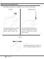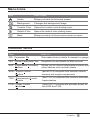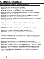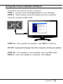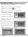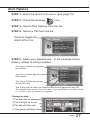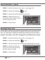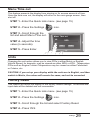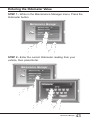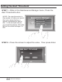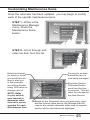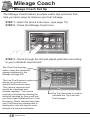
1
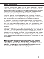
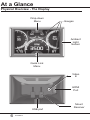
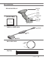
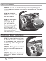
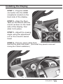
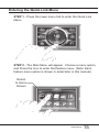
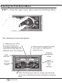
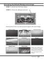
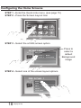
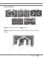
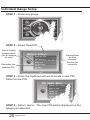
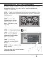
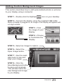
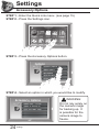
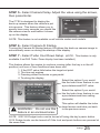
Table of Contents
4
Read Me
6
At a Glance
10
Getting Started
14
Display Set Up
4 Safety Warning & Caution
5 Safety Guidelines
6 Physical Overview - The Display
7 Accessories
8 Touch Screen Gestures
9 Menu Icons
9 Common Terms
10 Download the Fusion Update Software
11 Using the Fusion Update Software
12 Cable Installation
12 Windshield Mount Installation
13 Installing the Display
14 OEM Selection Menu
15 Entering the Quick Link Menu
16 Entering the Pull Down Menu
17 Changing the Default Background Image
18
 Configuring the Home Screens
20 Individual Gauge Setup
21 Calibrating Pitch, Roll, & G-Force Gauges
22 Download and Install MyStyle Software
23 Adding Custom Background Images
24Settings
24 Accessory Options
26 Vehicle Options - Tire Size
27 Alert Options
28 Sound Duration - Alerts
28 Backlight Auto dim
29 Menu Time out
29 Units
29 Factory Reset
30Diagnostics
30 Read DTCs
31 Clear DTCs
31 Clear On Start
32 Manual DPF Regeneration
33 DPF Regeneration Explained
34 Injector Balance Rates
36
Performance Testing
38
Data Log
36 0-60 & Quarter Mile
37
 Horsepower
38 Data Logging Explained
39 Retrieving Data Using MyStyle
40Records
40 Records Explained
41Help
41
42
 Help Menu Explained
Maintenance Manager
42 Turn on Maintenance Manager
43 Entering the Odometer Value
44 Setting the Alert Threshold
45 Customizing Maintenance Items
46
Mileage Coach
48
Additional Features
46 Mileage Coach Set Up
48 EFI Live™
48 Smarty-POD™
49 EAS 12V Power Kit
50Appendix
50 Limited 1 Year Warranty
51 Important Information about your Vehicle’s Warranty
52 Commonly Used Acronyms
53 Trouble Shooting Guide
53 OEM EGT Locations - Diesel Trucks Only
Read Me
Safety Warning & Caution
Throughout this User Manual you will see important messages
regarding your safety or the protection of your vehicle. These
messages are designated by the words WARNING or CAUTION.
WARNING indicates a condition that may cause serious
injury or death to you, your passengers or others nearby.
Pay careful attention to these Warning messages, and always
comply with them. They could save a life.
CAUTION indicates a condition that could cause damage to
your vehicle. It is important to install and operate your
product in conformance with instructions in this Manual.
Caution alerts you to particularly important things that will
keep your vehicle operating properly.
The Edge Product you have purchased is a high-performance
product. As such, it does present some risks of which you should
be fully aware. Do not use this product until you have carefully
read the following safety information and the Owner Agreement.
NOTE: After the display has been
installed, a warning screen will appear (3) different times. If
you agree with the agreement, press the [YES] button to
continue.
4
Read Me
Safety Guidelines
1. Do not exceed legal speed limits on public roadways. Use any
enhanced speed capabilities of this product only in closed circuit,
legally sanctioned racing environments expressly for this purpose.
Loss of control from speeding on a public road could seriously
injure you, your passengers, or others on the roadway.
2. Do not operate the device while driving. Perform all adjustments or changes while stopped. Changing a setting while under
way can interfere with your attention to roadway conditions.
3. “Stacking” performance-enhancing devices or other improper
installation can cause power train failure on the road. Other products may have features incompatible with your Edge device. Follow all installation and operating instructions, and do not stack
products.
4. Some modifications may affect other parts of your vehicle. For
example, if you remove/adjust the speed limiter in your vehicle, be
sure your tires and other components are rated for the increased
speeds they will have to withstand. Not doing so can lead to loss
of vehicle control. Modify the speed limiter only for use in closed
circuit, legally sanctioned racing environments, not for use on public roadways.
WARNING - Misapplication or misuse of this product
could lead to a serious or fatal accident. Comply with all
safety information in this manual, and your vehicle owner’s
manual. Follow safety, installation and operating instructions in this User Manual to assure proper use.
Read Me
5
At a Glance
Physical Overview - The Display
Drop-down
Menu
Gauges
Ambient
Light
Sensor
Quick Link
Menu
Video
In
HDMI
Port
USB port
6
At a Glance
Mount
Receiver
Accessories
Windshield Mount
Suction
Cup
Cam
Lever
Adjustment
Nut
Alcohol Wipe
Dual-Tab
Mount
Isopropyl
OBDII to HDMI cable
HDMI
EAS
OBDII
Mini USB Cable
Zip-Ties
At a Glance
7
Touch Screen Gestures
Use these gestures to navigate and control the display.
Press
Hold & Drag
The Press gesture is used
to select options, input
values, enter menus, etc.
The Hold & Drag gesture
is used to drag up or down
menus, and scroll through
menu items.
Swipe
The Swipe gesture is used to
scroll through gauge screens.
8
At a Glance
Menu Icons
Icon
What it does
Home
Brings you back to the home screen
Background
Changes the background Image
Custom Color
Opens the custom color picking menu
Default Color
Opens the default color picking menu
Back
Brings you back to the previous screen or menu
Common Terms
Term
What it is
PID - Parameter IDs
Data taken from a vehicle & viewed in a gauge
DPF - Diesel Particulate Filter
Required on new diesels to filter out soot
EAS - Expandable Accessory
System
Allows you to connect aftermarket sensors and
other devices such as turbo timers
ECM - Engine Control
Module
(aka ECU) A computer that controls various
sensors and engine components
TCM - Transmission Control
Module
(aka TCU) A computer that controls automatic
transmissions
PCM - Power Control
Module
(aka PCU) Combines and provides power for
the ECM and TCM
At a Glance
9
Getting Started
Download the Fusion Update Software
A computer with internet access is required:
STEP 1 - Go to www.edgeproducts.com
STEP 2 - Click the UPDATES tab, then DOWNLOAD.
STEP 3 - Open the FusionClientSetup.exe file, then click Run.
STEP 4 - Click Next to begin.
STEP 5 - Choose a folder location, then click Next to continue.
STEP 6 - Click Next to confirm the installation.
STEP 7 - Click the OK button if during the installation, the following
message appears:
“These drivers are not Windows Logo or WHQL verified. If you are
asked, please choose to install them anyway.”
STEP 8 - Click Close to exit once the installation is complete.
STEP 9 - Double click the Fusion Icon on your desktop.
STEP 10 - Click on the Create a New User option.
STEP 11 - Fill in the required information and click Save.
An e-mail containing your fusion password will be sent to the e-mail you
used in the form. Use this password to login into Fusion. (NOTE: The
password is case sensitive)
STEP 12 - Double click the Fusion Icon on your desktop.
STEP 13 - Plug the display into the computer using the USB cable.
STEP 14 - If asked, choose “Yes, this time only”, then click Next.
STEP 15 - Select Install the software automatically then Next.
STEP 16 - If you’re asked to “Continue Anyway” or “STOP installation” click Continue Anyway then click Next to complete the
hardware wizard.
10
Getting Started
Using the Fusion Update Software
A computer with internet access is required:
STEP 1 - Double click the Fusion Icon on your desktop.
STEP 2 - When asked, plug the display into the computer
using the supplied USB cable.
STEP 3a - If an update is available, click YES to continue.
DO NOT unplug the display from the computer during an update.
STEP 3b - If an update is not available, click the OK button.
STEP 4 - Once the update is complete, click Close.
Getting Started
11
Cable Installation
STEP 1 - Locate the On Board Diagnostics II (OBDII) port.
(This connector is typically found directly below the driver side dash
console.)
STEP 2 - Plug the
OBDII connector into
the vehicle port.
HDMI
STEP 3 - Route the
HDMI end up the
driver side dash.
(On most vehicles,
the side panel may be
removed to expose
the underside of the
dash for easier routing.
Leave exposed until
after the display is installed.)
Windshield Mount Installation
STEP 1 - Use the Alcohol Wipe
to liberally clean the windshield
in the area you plan to place the
suction cup. Allow the glass to
fully dry.
STEP 2 - Firmly press and hold
the suction mount against the
glass.
STEP 3 - Rotate the Cam Lever
towards the glass to create the
suction.
12
Getting Started
OBDII
Installing the Display
STEP 1 - Plug the HDMI
connector into the HDMI
receptacle located on the
back side of the display.
STEP 2 - Align the Dual
Tabs on the Mount with the
mount receiver on the back
side of the display, then
slide it into place.
STEP 3 - Adjust the viewing
angle using the adjustment
nut on the mount’s swivel
head.
STEP 4 - Pull any extra cable back
behind the pillar and dash. (Re-install any panels removed
during the Cable Installation.)
Getting Started
13
Display Set Up
OEM Selection Menu
Once the installation is complete, and you first plug the device
into the OBDII port, the OEM selection menu will appear.
OEM Selection
Domestic
Import
STEP 1 - Turn the vehicle to the ON or RUN key position.
STEP 2 - Select one of the three options available:
Domestic
Ford || Chrysler/Dodge || GM/Chevy || Other
Import
BMW || Mazda || Mini Cooper || Mitsubishi || Nissan || Subaru || Other
STEP 3 - Follow the on screen
instructions. The Main Gauge screen will appear.
14
Display Set Up
Entering the Quick Link Menu
STEP 1 - Press the lower menu tab to enter the Quick Link
Menu.
STEP 2 - The Main Menu will appear. Choose a menu option,
and Press the Icon to enter that feature menu. (Note: Each
feature menu option is shown in detail later in this manual)
Return
to Home
Screen
Display Set Up
15
Entering the Pull Down Menu
STEP 1 - Press the upper menu tab to enter the Pull Down Menu.
The following screen will appear:
If notifications are active
they will be listed here.
If multiple notifications are
active at one time they will
alternate every few seconds.
These buttons toggle the power
level which is displayed between the two.
Change
Background
Image
Light
Indicator
Adjust
Background
Color
&
Opacity
Return
to Home
Screen
When the Drop Down menu is closed, this tab alerts
you to any notifications that are available by changing
color.
16
Display Set Up
Changing the Default Background Image
STEP 1 - Enter the Pull Down Menu.
STEP 2 - Press the Background icon.
Each press of the icon will cycle through to the next image:
Honey Comb
(Red/Blue/Green) Flash
Digital Camo
Wild Fire
Scratched
White Wash
Diamond Plate
Simple
Refer to the “Adding Custom Background Images”
section of this manual for
information on how to add
your own images to the
display.
Display Set Up
17
Configuring the Home Screens
STEP 1 - Enter the Quick Link menu. (see page 15)
STEP 2 - Press the Screen Layout Icon
STEP 3 - Select the a DAQ screen option
Screen Layout
Background
DAQ Screen 1 - Master
DAQ Screen 2 - Accelerometer
STEP 4 - Select one of the screen layout options
DAQ Screen 1
Master
Digital
Retro
Needles
Accelerometer
18
Display Set Up
Press to
select a
default
Background
image
Layout Options
Master Gauge
Digital Gauges
Needle Gauges
STEP 5 - Return to the Home
Retro Gauge
Accelerometer Gauges
screen.
STEP 6 - Swipe horizontally to switch between your selected
layouts.
Display Set Up
19
Individual Gauge Setup
STEP 1 - Press any gauge.
STEP 2 - Select New PID
Some Analog
gauges allow
you to change
its color
Battery Voltage
Please Refer
to Alert
Options
Section for
more info
Select New PID
Alert Settings
Gauge Color
Describes the
selected PID
PID Information
Exit Menu
STEP 3 - Press the Up/Down arrows to locate a new PID.
Select a new PID.
PID Select Menu
Manifold Abs Pressure
Mass Air Flow
Mileage Avg.
Mileage Inst.
Mileage Coach
STEP 4 - Return Home. The new PID will be displayed on the
gauge you selected..
20
Display Set Up
Calibrating Pitch, Roll, & G-Force Gauges
Once the display has been installed, and is mounted in a semipermanent position, the Pitch, Roll, & G-Force gauges will
need to be calibrated.
STEP 1 - Refer to Configuring the Home Screen section in this
manual. Assign the Accelerometer screen layout to one of the
DAQ screens.
STEP 2 - Once the
Accelerometer Gauge
is displayed, enter the
Quick Link menu. (see
page 15)
STEP 3 - Press the Settings
STEP 4 - Press the Up/
Down arrows until the
Calibrate Accelerometer
option is available.
STEP 5 - Press the
Calibrate Accelerometer
option.
icon.
Options
Calibrate Accelerometer
Units: English
Smarty Live Off
Factory Reset
STEP 6 - Return home to the
gauge screen.
The Pitch, Roll, & G-Force gauges
should all read zero.
Display Set Up
21
Download and Install MyStyle Software
MyStyle is software that allows you to customize your display
background image and manage your EAS devices.
A computer with internet access is required:
STEP 1 - Go to www.edgeproducts.com
STEP 2 - Click the UPDATES
tab, then Mystyle
DOWNLOAD.
STEP 3 - Open the MyStyleSetup.exe file, then click Run.
STEP 4 - Click Next to begin.
STEP 5 - Choose a folder location,
then click Next to continue.
STEP 6 - Click Next to confirm the
installation.
STEP 7 - Click the OK button if during
the installation, the
following message appears:
“These drivers are not Windows Logo or WHQL verified. If you are asked,
please choose to install them anyway.”
STEP 8 - Click Close to exit once the installation is complete.
22
Display Set Up
Adding Custom Background Images
This section describes how to add personalized photos or pictures
to your display using a computer.
STEP 1 - Double-click the MyStyle
icon on your desktop.
STEP 2 - Connect the display using the supplied USB cable.
When a display is plugged in, an image of the display will appear with
a 9 digit number.
STEP 3 - Click
the image of your
display.
STEP 4 - Choose
to Customize the
Display.
STEP 5 - Select an Image to replace.
STEP 6 - Select the
Open Image button.
STEP 7 - Use the available tools to size and
align your image.
STEP 8 - Click the
Save Background button
to save your progress.
This will also save the
new background image
to you display.
Display Set Up
23
Settings
Accessory Options
STEP 1 - Enter the Quick Link menu. (see page 15)
STEP 2 - Press the Settings icon.
STEP 3 - Press the Accessory Options button.
Options
Accessory Options
Vehicle Options
Alert Options
Sound Duration - 3 sec
Screen Layout
STEP 4 - Select an option in which you would like to modify.
Accessory Options
Camera Delay - 2.0 sec
Camera at Startup: On
Turbo Cool Down Setup
24
Settings
WARNING:
Do not rely solely on
the camera image
for backing up. It
is possible for the
camera image to
freeze.
STEP 5 - Select Camera Delay. Adjust the value using the arrows,
then press Enter.
The CTS2 is designed to display the
back-up camera when the vehicle is put
into reverse. This feature allows you to
specify how many seconds you would like
the camera view to wait before it shows
up on the display.
Camera Delay
2.0
EXIT
ENTER
NOTE: This feature is not available on all vehicle makes and models.
STEP 6 - Select Camera At Startup.
Turning the Camera At Startup feature ON allows the back-up camera image to
automatically come on during the startup of the display.
STEP 7 - Select Turbo Cool Down Setup. (NOTE: This feature is only
available if an EAS Turbo Timer display has been installed.)
This feature allows the engine to continue running (after the key is in the-off
position) until one of four conditions have been met:
1. If the EGT value falls below the target set point.
2. The time set expires
3. Pressing either the brake or gas pedal.
4. Touching the display.
Select this option if you would
like the turbo timer feature to use
Turbo Cool Down Setup
a pre-determined EGT value.
Turn On and Use EGT
Turn On and Use Time
Do Not Use Turbo Timer
WARNING: Do not use this
feature in an enclosed area.
Select this option if you would
like the turbo timer feature to use
a pre-determined time setting
(seconds).
This option will disable the turbo
timer feature and take you back
to the previous menu.
NOTE: 2007-09 Dodge trucks can be turned off using the key’s panic button.
2010 Dodge trucks can be turned off if the lock and panic buttons are pressed at
the same time.
Settings
25
Vehicle Options - Tire Size
The display is capable of re-calibrating the MPH PID. In order for this to
happen, you will need to enter a tire size.
STEP 1 - Enter the Quick Link menu. (see page 15)
STEP 2 - Press the Settings
icon.
STEP 3 - Select Vehicle Options, then select Tire Size.
STEP 4 - Select the size option
that best fits your application:
Tire Size
Stock Size - 0.0 inches
Modified Size - 0.0 inches
Stock Size = Stock Tires
Modified Size = Non-Stock Tires
STEP 5 - Choose the tire format that best fits your application,
and insert the information.
English = height(XX) / width(XX.X / wheel size (RXX)
P-Metric = width(XXX) / aspect ratio(XX) / diameter (RXX)
Circumference = the outer circumference of the tire (mm)
Height = The height of the tire (from ground to top of tire)
Return to Stock = Erases any tire info you have entered,
and returns the tire size to the original default setting.
Choose Tire Format
English - XX
XX.X RXX
P-Metric - XXX
XX RXX
Circumference - XXXXmm
Height - XX inches
Return to Stock
STEP 6 - Choose the tire format that best fits your application,
and insert the information as shown below.
TIRE SIZE SCREEN
Tire Size Circumfer. - mm
___ / __ R __
2000
OR
EXIT
26
Settings
ENTER
Alert Options
STEP 1 - Enter the Quick Link menu. (see page 15)
STEP 2 - Press the Settings
icon.
STEP 3 - Select Alert Options from the list.
STEP 4 - Select a PID from the list.
Press to toggle the
Alerts Off or On
Alert Options
Alerts are Off
Battery Voltage
Corrected Vehicle Speed
Cylinder Head Temp
EAS EGT
STEP 5 - Make your adjustments. In the example below,
battery voltage is being modified.
Turn On or Off the alert system
for all PIDs.
Battery Voltage
Alert System On
Turn On or Off this specific
PID’s alerts.
Turn On or Off the alert sound
for this PID only.
Bat V Alert On
Sound On
Set Point: 11.5
Exit Menu
This is the point at which you want the alert to be triggered for this PID.
The example above shows 11.5 as the value. If the display detects a battery voltage
of 11.5 volts or less, the alert will be triggered.
During an alert:
1)The alert will be displayed
2)This will light up in red
3)The tab will flash red
4) The gauge will flash red
Settings
27
Sound Duration - Alerts
STEP 1 - Enter the Quick Link menu. (see page 15)
STEP 2 - Press the Settings
icon.
STEP 3 - Select Sound Duration from the list.
STEP 4 - Adjust the time (in
seconds) to the length of time
an alert should sound.
Sound Duration
2
EXIT
STEP 5 - Press Enter
ENTER
Backlight Auto dim
Each display is equipped with a light sensor that detects how much light is entering the vehicle cab. During the day, the display will be at it’s maximum brightness. As it gets darker outside, the display will automatically dim according to
the amount of sunlight. If the value is kept at 99%, the display will be as dim as
possible. If the value is set to 50%, the display will only be half as dim at night.
STEP 1 - Enter the Quick Link menu. (see page 15)
STEP 2 - Press the Settings
icon.
STEP 3 - Scroll through the list and select Backlight Auto dim.
STEP 4 - Adjust the percent
value for how much dimming
will take place at night.
STEP 5 - Press Enter.
28
Settings
Auto dim Percent
99
EXIT
ENTER
Menu Time out
This feature prevents the display from staying on for excess amounts of time.
Once the time runs out, the display will return to the main gauge screen, then
shut off.
STEP 1 - Enter the Quick Link menu. (see page 15)
STEP 2 - Press the Settings
icon.
STEP 3 - Scroll through the
list and select Menu Time out.
Menu Time out
300
STEP 4 - Adjust the time
value (in seconds).
EXIT
ENTER
STEP 5 - Press Enter.
Units
Changing the unit option allows you to view PIDs in either Metric or English.
Vehicle Speed, for example, may be viewed as either MPH or KPH. Temperature
PIDs such as Engine Coolant Temperature may be viewed as either Fahrenheit
or Celsius, etc.
CAUTION: If you set up your display while the units are in English, and then
switch to Metric, the values will remain the same, and not be converted.
Factory Reset
This feature will return the display to the factory default settings. All records and
input data will be deleted and not recoverable.
STEP 1 - Enter the Quick Link menu. (see page 15)
STEP 2 - Press the Settings
icon.
STEP 3 - Scroll through the list and select Factory Reset.
STEP 4 - Press YES
Settings
29
Diagnostics
Read DTCs
When your PCM detects a problem with your vehicle it sets a
trouble code, and most times a “Check Engine” light on your
dash is activated. These codes can be retrieved and used to
help diagnose specific issues.
STEP 1 - Enter the Quick
Link menu. (see page 15)
STEP 2 - Press the Diagnostics icon.
STEP 3 - Select Trouble
Codes.
Diagnostics
Trouble Codes
Performance Tests
Records
Mileage Coach
Data Logging
STEP 4 - Select Read DTCs.
STEP 5 - If a code is listed,
select the code to see a brief
explanation of the issue.
Alert Settings
P0230
P1000
If a code is shown, write down the information given. You can use this
code number to research the particular issue. The internet is a good
resource for looking up most codes.
30
Diagnostics
Clear DTCs
This feature allows you to clear most DTCs. This will erase any
codes currently set. If the codes come back we recommend
you see a qualified mechanic who can accurately diagnose and
repair the problem.
STEP 1 - Enter the Quick Link menu. (see page 15)
STEP 2 - Press the Diagnostics
icon.
STEP 3 - Select Trouble Codes.
STEP 4 - Select Clear DTCs.
Clear On Start
This feature is not available on all products.
In some instances, DTCs may need to be cleared every time the
truck starts or the truck will go into “limp” mode.
NOTE: Fords and Chevy’s are able to clear codes while the truck is running. Dodge Trucks however may require you to clear only when the key
is on and the engine is not running.
STEP 1 - Enter the Quick Link menu. (see page 15)
STEP 2 - Press the Diagnostics
icon.
STEP 3 - Select Trouble Codes.
STEP 4 - Select Clear On Start to toggle between Yes and No.
Diagnostics
31
Manual DPF Regeneration
Available only on specific Diesel Trucks Only
Manual regeneration allows you to manually clear out the Diesel
Particulate FIlter (DPF). Completeing a manual regeneration
cycle will clear the soot mass in the filter, and lower exhaust
back pressure to improve exhaust flow.
STEP 1 - Enter the Quick
Link menu. (see page 15)
STEP 2 - Press the
Diagnostics icon.
STEP 3 - Select the Manual
Regen option.
STEP 4 - When prompted,
touch the screen to continue.
Diagnostics
Trouble Codes
Manual Regen
Trans Relearn
Performance Tests
Records
NOTE: When manually initiating a regeneration cycle, some vehicles will
require a drive cycle (i.e. you have to drive the vehicle some distance) while
others may allow you to initate a Service Regeneration where you can leave
the vehicle parked and the engine running. If the latter is the case, be sure to
use the following guidelines.
1. Park the vehicle outdoors and keep people, other vehicles, and combustible
materials away from it.
2. Do not leave the vehicle unattended.
3. Do not connect any shop exhaust hoses or vents to the tail pipe.
32
Diagnostics
DPF Regeneration Explained
CAUTION: Exhaust temperatures may be greater than 300C (572 F) during
service regeneration.
CAUTION: Due to the elevated temperatures during this procedure, open
the hood and keep the front of the vehicle away from anything impeding
air flow to the radiator.
DPF REGENERATION
If you own a newer diesel powered vehicle, your vehicle is equipped with
a diesel particulate filter (DPF). This filter is used in conjunction with a
diesel oxidation catalyst. Together they work to reduce the amount of
soot and emissions emitted from the tailpipe. As soot builds up in the
DPF it will begin restricting flow. The soot that gathers is automatically
purged in one of two ways: Passive Regeneration & Active Regeneration. Both methods occur automatically and require no action on your
part. During either of these regeneration methods, you may notice an
increase or change in the exhaust noise & increased Exhaust Gas Temperature (EGT).
PASSIVE REGENERATION
Passive regeneration occurs when the exhaust gas temperature (EGT)
reaches an appropriate level in order to oxidize or burn soot to clean the
DPF. This method can happen as a result of normal engine operating
conditions, typically when the engine reaches an (EGT) high enough to
burn off the soot (i.e. heavy towing, high load conditions, etc). If EGTs
do not get hot enough to cause passive regeneration, your truck’s engine-control system automatically initiates an active regeneration.
ACTIVE REGENERATION
During active regeneration, the truck computer cleans the DPF by raising the exhaust temp to a point where the soot is burned away. This is
accomplished through various engine actions which raise the EGTs in
the oxidation catalyst/DPF system to a level where the soot is burned
off. After the soot is burned off, the EGTs and back pressure (restriction)
fall back to normal levels. In order to help you know the status of DPF
Regeneration, the device will show in the alerts section of the drop down
menu anytime active regeneration is happening.
Diagnostics
33
Injector Balance Rates
Available only on specific GM/Chevy Trucks Only
Injector Balance Rates are used to determine if all injectors are operating
within the correct tolerances. If you are experiencing a misfire, knock,
excessive smoke, or rough running conditions with no DTCs, this option
can help identify faulty injectors. The balance rates are the fuel adjustments for each individual cylinder based on the variations in engine
crankshaft speed. These will change depending on if the transmission is
int Neutral or Drive. Injectors that read outside of the +/- 4.0 in park/neutral or +/- 6.0 in drive may be faulty.
STEP 1 - Enter the Quick
Link menu. (see page 15)
STEP 2 - Press the
Diagnostics icon.
STEP 3 - Select the Injector
Balance Rates option.
STEP 4 - When prompted,
touch the screen to continue.
34
Diagnostics
Diagnostics
Injector Balance Rates
Manual Regen
Trans Relearn
Performance Tests
Records
STEP 5 - What each injector
value while in Park/Neutral, and
then while in Drive.
STEP 6 - Touch any gauge to
return home.
Injector Balance Rates
Inj1 Bal Rate
Inj2 Bal Rate
1.0
Inj4 Bal Rate
-1.0
2.0
Inj5 Bal Rate
3.0
Inj6 Bal Rate
Inj3 Bal Rate
0.0
2.0
Inj7 Bal Rate
1.0
Inj8 Bal Rate
3.0
If you suspect a faulty injector, we recommend consulting a
professional diesel mechanic who can verify the issue and
also perform a cylinder power balance test to further diagnose.
Diagnostics
35
Performance Testing
0-60 & Quarter Mile
Performance tests can be helpful for measuring performance gains after
vehicle modifications have been made. The results recorded during
these test will likely differ from what you’ll see on a drag-strip or other
racing venues. Incorrect speedometer calibration, data sample rate,
and tire slippage can cause miscalculations in the displayed results.
STEP 1 - Enter the Quick
Link menu. (see page 15)
STEP 2 - Press the
Performance Testing
icon.
STEP 3 - Select either the
0-60 or Quarter Mile option.
Performance Tests
0-60
Quarter Mile
STEP 4 - Bring the vehicle to
a complete stop.
STEP 5 - Use the drag strip
style light tree on the left of the
screen to know when to begin
accelerating. Once you have
reached 60 mph (or a quarter
mile), the test will show as
completed.
Horsepower
Instructions
Speed (mph)
0
Distance (ft)
0
Time (sec)
0
Accelerate to 60 mph...
STEP 6 - Touch the screen to
exit the test.
WARNING: Do not use the Performance Tests feature to break any traffic laws.
36
Performance Testing
Horsepower
NOTE: Before using the Horsepower test, the vehicle weight (aka curb weight)
must be entered first. The curb weight is the total weight of a vehicle with standard equipment, all necessary operating consumables (e.g., motor oil, coolant),
a full tank of fuel, with no passengers or cargo.
STEP 1 - Enter the Quick
Link menu. (see page 15)
STEP 2 - Press the
Settings icon.
STEP 3 - Scroll through
the menu, then select the
Vehicle Weight option.
Settings
Vehicle Weight - 6800
STEP 4 - Use the UP & DOWN
arrows to enter the weight.
Calibrate Accelerometer
Units: English
Smarty Live On
Vehicle Weight
Factory Reset
6800
EXIT
STEP 5 - Return Home
ENTER
and re-enter the Quick Link menu.
STEP 6 - Select the Performance Testing
icon.
STEP 7 - Select the Horsepower option.
STEP 8 - Bring the vehicle to a complete stop.
STEP 9 - Use the drag strip style light tree on the left of the
screen to know when to begin accelerating. Touch the screen to
exit the test.
Performance Testing
37
Data Log
Data Logging Explained
The data logging feature allows you to record all of the available
PID data on your display. This information can be retrieved and
viewed using the MyStyle software package.
NOTE: The display also runs background tasks which are also recorded. This information can be ignored.
STEP 1 - Enter the
Quick Link menu. (see
page 15)
STEP 2 - Press the
Data Log icon.
STEP 3 - Select one of the (5) Data Run options. This will turn
the run On or Off.
Data Logging
NOTE: Only one run can be
turned on at a time.
STEP 4 - Select the Home
button to return to the main
gauge screen. The display is
now in recording mode.
Data Run 1: Off
Data Run 2: Off
Data Run 3: Off
Data Run 4: Off
Data Run 5: Off
STEP 5 - Once you have recorded for a desired period of time,
return to the Data Logging menu and turn Off the run.
NOTE: The maximum amount of Data Logging time depends on how many
items you are logging at once. This may be anywhere from 15 to 20 minutes
total. Once the limit is reached, the Data Logging feature will be automatically
shut off.
NOTE: If you turn the same Data Run back On, the previous data will be
erased and a new recording session will begin. If the indicator light is red,
there is currently a recorded file associated with that run.
38
Data Log
Retrieving Data Using MyStyle
This section describes how to retrieve the data recorded during a
Data Logging recording session. If you have not yet installed
MyStyle refer to the Display Set Up section of this manual.
STEP 1 - Double-click the MyStyle
icon on your desktop.
STEP 2 - Connect the display using the supplied USB cable.
When a display is plugged in, an image of the display will appear with
a 9 digit number.
STEP 3 - Click
the image of your
display.
STEP 4 - Select
Data Logs.
STEP 5 - Click the Save File As button and
save the file.
STEP 6 - Locate the saved file on
your computer and open it. The file
will be saved as a .CSV file and can
be opened using Microsoft Excel or
similar.
Data Log
39
Records
Records Explained
Records contain certain parameters for later review. This is useful after completing a performance test on the drag strip, at a sled
pull, or when you are trying to trouble shoot a particular issue.
STEP 1 - Enter the Quick
Link menu. (see page 15)
STEP 2 - Press the
Records icon.
STEP 3 - Scroll through the list
to view all records.
STEP 4 - Press, hold, and
release any individual record
to reset it to default. All other
records will remain as is.
Records
Clear All
0 to 60:
0.0s
Boost psi:
20
ECT F:
195
MPH:
56
STEP 6 - Press, hold, and release the Clear All option to reset
all values to zero.
40
Records
Help
Help Menu Explained
The Help Menu contains useful information about your display,
and the vehicle it is currently plugged into. It also contains Edge
Products contact information and Technical Support tools.
STEP 1 - Enter the Quick
Link menu. (see page 15)
STEP 2 - Press the Help
icon.
STEP 3 - Select the option that best describes your need:
Product Info (Display)
•
•
•
•
•
•
•
Version
Application Version
Calibration Version
Firmware (BC) Version
FPGA Version
MSP430 Version
Serial Number (used to identify your display in the software update process and
during Technical Support calls)
Product Info (EAS)
If you have an EAS device installed on your vehicle and plugged into your display,
another Product Info screen will be available. It will list your EAS device’s Firmware
Version as well as its serial number.
Vehicle Info
Displays important information about your vehicle that is used by technical support
to trouble shoot issues.
Contact Info
Shows our website, company address, the technical support email address, and the
technical support phone number.
Tech Support Tools
This menu should only be used when requested by Edge Products Technical Support personnel.
Help
41
Maintenance Manager
Turn on Maintenance Manager
STEP 1 - Enter the Quick Link menu. (see page 15)
STEP 2 - Press the Maintenance Manager Icon.
STEP 3 - Select the Maintenance Mgr button to turn the
feature on. (This button toggles the feature off and on.)
Maintenance Manager
Maintenance Mgr.
On
Maintenance Items
Odometer: 10,400
Alert Threshold:
42
Maintenance Manager
100
Entering the Odometer Value
STEP 1 - While in the Maintenance Manager menu, Press the
Odometer button.
Maintenance Manager
Maintenance Mgr.
On
Maintenance Items
Odometer: 10,400
Alert Threshold:
100
STEP 2 - Enter the current Odometer reading from your
vehicle, then press Enter.
Maintenance Manager
Maintenance Mgr.
On
Maintenance Items
Odometer: 10,400
Alert Threshold:
100
Maintenance Manager
43
Setting the Alert Threshold
STEP 1 - While in the Maintenance Manager menu, Press the
Alert Threshold button.
NOTE: The alert threshold is
the number of miles you would
like to be alerted before a
specific maintenance item is
due. In the example above,
you would be alerted 100 miles
before the actual mileage it is
due.
Maintenance Manager
Maintenance Mgr.
On
Maintenance Items
Odometer: 10,400
Alert Threshold:
100
STEP 2 - Press the arrows to adjust the value. Then press Enter.
MM Alert Threshold
98
EXIT
44
Maintenance Manager
ENTER
Customizing Maintenance Items
Once the odometer has been updated, you may begin to modify
each of the specific maintenance items.
STEP 1 - While in the
Maintenance Manager
menu, Press the
Maintenance Items
button.
Maintenance Manager
Maintenance Mgr.
On
Maintenance Items
Odometer: 10,400
Alert Threshold:
STEP 2 - Scroll through and
select an item from the list.
100
Maintenance Items
Change Air Filter
Change Axle Fluid
Change Cabin Air Filter
Change Engine Coolant
Change Engine Oil
Enter the interval
(in miles) in which
you would like the
item to alert you.
In this example,
you will be Alerted
every 3000 miles to
change your oil.
NOTE: Refer
to your vehicle
user manual to
determine what
interval is recommended for each
Maintenance Item.
Turning On an alert
means the item is
now being managed
Engine Oil
Alert: On
Service Performed
Interval: 3000
Next Service: 52180
Exit Menu
Press the Service
Performed button
each time the item
is serviced. This will
reset the mileage for
the Next Service.
Based on the Odometer value you previously input,
and the Interval value above, the Mileage that will
read on the vehicle odometer at the time of required
service will be calculated and displayed.
Maintenance Manager
45
Mileage Coach
Mileage Coach Set Up
The Mileage Coach feature provides useful tips and tools that
help you learn ways to improve your fuel mileage.
STEP 1 - Enter the Quick Link menu. (see page 15)
STEP 2 - Press the Mileage Coach Icon.
STEP 3 - Scroll through the list and adjust each item according
to your individual requirement.
The Clear Fuel Average
option clears the calculated
average displayed in the
Mileage Average PID.
The Last Fuel Economy option
allows you to enter your
actual Fuel Economy value.
This value is important and
should be calculated and
entered regularly. This can be
manually calculated by dividing the
distance travelled by how much fuel
you have used (Distance/Fuel = Fuel
Economy). Some vehicles have their
own Fuel Economy average that is
displayed in cab and may be used
instead of a manual calculation.
46
Mileage Coach
Mileage Coach
Clear Fuel Avg:
Last Fuel Econo:
0.00
0.00
Trip Odometer:
1250
Fuel Price: $
0.00
Mileage Cost: $
0.00
The Trip Odometer is used to
calculate the Trip Cost and
Fuel Average.
The Mileage Cost is a calculated
average based on how many
miles you have traveled and the
Fuel Price you entered.
The Trip Cost is calculated
from the Fuel Price and the
Trip Odometer values.
The Fuel Price is used to
calculate your Mileage and
Trip Costs.
Mileage Coach
Fuel Price: $
0.00
Mileage Cost: $
0.00
Trip Cost: $
1250
Mileage Coach Display
There are two ways to display
the Mileage Coach PID:
Show Difference
Displays the difference
between Instantaneous
and Average fuel mileage.
Show Values
Displays as: Instantaneous | Average.
Mileage Driving Tips
Mileage Driving Tips
are intended to give
you general information
regarding driving habits
or anything that will
help maximize your fuel
economy and overall
driving experience.
STEP 4 - Refer to the Individual Gauge Set Up section of this
manual to display one or all three Mileage Coach PIDs on the
main gauge screen.
Mileage Average displays the calculated average MPG or L/100km and is updated continuously while driving. The average is calculated only when the PID
is being displayed on the main Gauge Screen. This value will typically change
more during start/stop driving, and less on the highway.
Mileage Instantaneous - shows a conscientious driver how to vary the pressure on the gas pedal to save fuel every second. The value is displayed in
either MPG or L/100km.
Mileage Coach - takes the Average and Instantaneous values mentioned above
and creates a visual tool to help maximize your fuel economy. This PID is best
viewed using one of the Analog Gauge locations.
Mileage Coach
47
Additional Features
EFI Live™
Adjust EFI Live™ Tuned PCMS On-The-Fly!
On 2001-2005 LB7 and LLY Duramax engines, you can change
the power levels on-the-fly create by your EFI Live™ custom
tuning software.
STEP 1 - Use your EFI Live™ software to change your DSP5
Switch Type from “hard wire” to “serial”.
STEP 2 - Enter the pull
down menu.
STEP 3 - Use the UP/
DOWN arrow buttons on
your Insight to adjust EFI
Live™ tunes on-the-fly.
NOTE: Your current level will be displayed in the level indicator
box. 5 custom levels (1-5) are usable with this feature.
Smarty-POD™
If you have a Smarty device with the Power On Demand option
enabled, you have the option to adjust the Smarty levels with
your Insight. Follow these instructions to turn this option on or
off using your insight.
STEP 1 - Program the vehicle using the Smarty device.
STEP 2 - Enter the pull up
menu as shown on page 15.
STEP 3 - Press the Setting
Icon.
48
Additional Features
STEP 4 - Choose to turn ON the Smarty Live feature.
STEP 5 - Return to the
Main Gauge Screen, and
enter the pull down menu.
STEP 6 - Adjust the
power levels using the
UP/DOWN arrows.
EAS 12V Power Kit
An additional adapter kit may be purchased allowing you to connect an Insight to a non-OBDII equipped vehicle.
This kit works along with our EAS system giving you the ability to
install and monitor multiple sensors.
For more information on how to install and operate this functionality, refer to the EAS User Manual.
Additional Features
49
Appendix
Limited 1 Year Warranty
Edge Products, LLC, (hereafter “SELLER”) gives Limited Warranty as
to description, quality, merchantability, fitness for any product’s purpose,
productiveness, or any other matter of SELLER’s product sold herewith.
The SELLER shall be in no way responsible for the product’s open use and
service and the BUYER hereby waives all rights other than those expressly
written herein. This Warranty shall not be extended or varied except by a
written instrument signed by SELLER and BUYER.
The Warranty is Limited to one (1) year from the date of sale and limited
solely to the parts contained within the product’s kit. All products that are in
question of Warranty must be returned shipping prepaid to the SELLER and
must be accompanied by a dated proof of purchase receipt. All Warranty
claims are subject to approval by Edge Products Inc.
Under no circumstances shall the SELLER be liable for any labor charged or
travel time incurred in diagnosis for defects, removal, or reinstallation of this
product, or any other contingent expenses.
If the BUYER sends back a failed unit that is out of warranty and chooses to
buy a refurbished unit, the refurbished unit will only carry a 90 day warranty.
If the BUYER purchases a new unit at a predetermined discounted rate, it
will have the standard 1 year warranty.
Under no circumstances will the SELLER be liable for any damage or expenses insured by reason of the use or sale of any such equipment.
THE INSTALLATION OF THIS PRODUCT INDICATES THAT THE BUYER
HAS READ AND UNDERSTANDS THIS AGREEMENT AND ACCEPTS
ITS TERMS AND CONDITIONS. IN THE EVENT THAT THE BUYER
DOES NOT AGREE WITH THIS AGREEMENT, THE BUYER MAY
PROMPTLY RETURN THIS PRODUCT, IN A NEW AND UNUSED CONDITION, WITH A DATED PROOF OF PURCHASE, TO THE PLACE OF PURCHASE WITHIN THIRTY (30) DAYS FROM DATE OF PURCHASE FOR A
FULL REFUND.
NOTE: This warranty is void for any new products purchased through
auction web sites. Warranty is valid only for new products purchased
through Authorized Dealers (proof of purchase required for all warranty claims).
50
Appendix
Important Information about your Vehicle’s Warranty
Many of our customers ask, “Will your product void my vehicle’s manufacturer’s warranty?” While the answer is straightforward from a legal standpoint, it’s important to educate our customers (and all aftermarket consumers) on some industry realities and offer some common sense precautions to
minimize your risk. Edge is committed to providing quality products that are
safe to use. Our products do not cause damage to a vehicle when used as
intended.
CAUTION: Operate your vehicle within manufactures recommended
load and weight limits as shown in the Manufactures Operator Manual.
Please keep in mind that towing in anything higher than the towing
level and hard driving in race or extreme performance levels using
Edge products is not recommended.
Consumers of aftermarket products are protected by the Federal Magnusson-Moss Warranty Act. The Act states that if something breaks on your vehicle and you take it in for warranty repair, the dealer must honor your warranty unless whatever modifications you have added to your vehicle actually
caused the problem in question. However, the reality is that many dealerships have been known to void warranties on vehicles that use aftermarket
products as a matter of policy. This applies in particular to those aftermarket
products that produce horsepower, such as performance enhancement
“chips,” modified intake manifolds, or aftermarket exhaust systems, regardless of product brand.
You have strong legal protection as a consumer in regard to your vehicle’s
warranty. However, Edge strongly recommends you always disconnect and
remove your Insight when you take your vehicle to a dealer for warranty
work. In addition, leaving the product connected may affect dealer diagnostic
analysis and scan tool functions. Edge makes every effort to produce product that can be easily removed.
NOTE: Even if you disconnect your unit, your dealer can detect the use
of any device—even if the unit has been removed.
Appendix
51
Commonly Used Acronyms
ACT = Air Charge Temp
ACV = Air Control Sensor
AOD = Automatic Overdrive Transmission
APP = Accelerator Petal Position
BAT = Battery Voltage
BCM = Body Control Module
BOO = Brake On/Off Switch
BP = Barometric Pressure Sensor
CCD = Computer Controlled Dwell
CCO = Converter Clutch Override
CDR = Crankcase Depression Regulator
CEL = Check Engine Light
CFI = Central Fuel Injection
CHT = Cylinder Head Temperature
CID = Cylinder Identification Sensor
CKP = Crank Position Sensor
CMP = Cam Position Sensor
CPS = Crankshaft Position Sensor
CS = Color Screen
CTS= Color Touch Screen
DPF = Diesel Particulate Filter
DTC = Diagnostic Trouble Codes
EAS= (Edge)Expandable Accessory System
ECA = Electronic Control Assembly
ECM = Electronic Control Module
ECT = Engine Coolant Temp
EDF = Electric Drive Fan Relay
EDIS = Electronic Distributor
EGO = Exhaust Gas Oxygen Sensor
EGR = Exhaust Gas Recirculation
EGRC = EGR Control Solenoid
EOT = Engine Oil Temperature
EVP = EGR Position Sensor
EVR = EGR Valve Regulator
FDM = Fuel Delivery Module
FPM = Fuel Pump Monitor
FRP = Fuel Rail Pressure
HEGO = Heated Exhaust Gas Sensor
IAT = Intake Air Temperature
ICM = Integrated Controller Module
IDM = Ignition Driver Module
ISC = Idle Speed Control
ITS = Idle Tracking Switch
52
Appendix
IVS = Idle Validation Switch (Diesel)
KAM = Keep Alive Memory
KOEO = Key On Engine Off
KOER = Key On Engine Running
KS = Knock Sensor
LOAD = Engine Load
LOS = Limited Operation Strategy
LPD = Line Pressure Desired
LUS = Lock-up Solenoid
MAF = Mass Airflow
MAFV = Mass Airflow Sensor Voltage
MAP = Manifold Absolute Pressure
MAT = Manifold Air Temp
MCU = Microprocessor Control Unit
MIL = Malfunction Indicator Light
MPH = Miles Per Hour
OHC = Over Head Camshaft
OSS = Output Shaft Speed
PCM = Powertrain Control Module
PFE = Pressure Feedback EGR Sensor
PIP = Profile Ignition Pickup
PSPS = Power Steering Pressure Switch
RPM = Revolutions Per Minute
SES = Service Engine Soon
SIL = Shift Indicator Light
SPARK = Spark Advance/Retard
SPOUT = Spark Output Signal
STAR = Self Test Automatic Readout
TAPS = Throttle Angle Position Sensor
TCM = Transmission Control Module
TFI = Thick Film Ignition System
TFT = Transmission Fluid Temperature
TGS = Top Gear Switch
TPS = Throttle Position Sensor
TQC = Torque Control
TSS = Turbine Shaft Speed
TTS = Transmission Temperature Switch
VAF = Vane Air Flow Sensor
VAT = Vane Air Temperature
VCT = Variable Cam Timing
VSS = Vehicle Speed Sensor
WAC = WOT A/C Cut-off Switch
WOT = Wide Open Throttle
Trouble Shooting Guide
SYMPTOM
Display beeps for two seconds
No display when the key is “on”
Fusion drivers will not install correctly
Camera picture is frozen
Display beeps quickly
Unit will not power on after vehicle is
started or after screen or buttons are
pressed
On Star®:
Unable to receive monthly On Star®
e-mail reports
POSSIBLE CAUSE
The unit is too hot due to direct sunlight
The screen has not yet been activated
The drivers were not successfully installed
Bad connections
Possible device malfunction
Typically this issue is caused by a blown
OBDii/Cigarette Lighter Fuse
SOLUTION
Once cooled, the display will turn on
Touch the screen or start the vehicle
Manually install the drivers
Double check your fuse and connections
Update the device using Fusion software
Replace fuse and test unit again
Having the display plugged into your
OBDii port may disturb On Star while
gathering information for their reports.
Unfortunately, there is no real solution
for this issue. You could try and call
On Star to see when they gather their reports, and unplug your device during that
time. This may or may not work for you.
OEM EGT Locations - Diesel Trucks Only
Dodge
Cummins
Exhaust Manifold
Post-DPF
EGT
Pre-DPF/Post-NOX
EGT
Post-DOC
EGT
Diesel Oxidation
Catalyst
Diesel
Particulate
filter
Muffler
NOX Filter
GM
Duramax
Post-DPF
EGT
Muffler
Pre-DPF/Post-Cat
EGT
Diesel
Particulate
filter
Diesel Oxidation
Catalyst
Ford
Powerstroke
Muffler
Pre-Turbo
EGT
Diesel
Particulate
filter
Post-DPF
EGT
Diesel Oxidation
Catalyst
Pre-DPF/Post-Cat
EGT
Pre-Cat
EGT
Exhaust Manifold
Appendix
53
Copyright© 2015 Rev 00
For additional questions not found in the user guide call:
Edge Products Technical Support: (888) 360-EDGE (3343) 6:00 am - 6:00 pm MST
To expedite your support call, please have your Vehicle Information,
Part Number, and Serial Number ready prior to calling Technical Support.