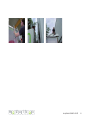
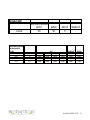
1
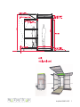
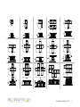
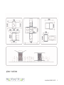
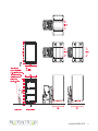
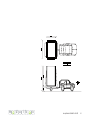
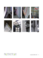
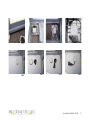
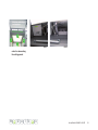
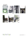
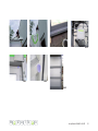
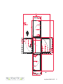
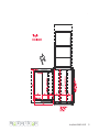
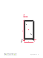
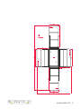
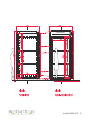
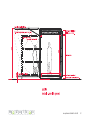
user manual modulbox mb²
Stand April 2007
Table of Contents
A. Product Description
B. General Information
C. Transport and Installation
D. Assembly Instructions
E. De-installation
F. Care and Maintenance
G. Warnings
H. Warranty Conditions
I. Specifications
J. Misc. / Contact
m
d u l b
4
8
10
18
32
36
38
42
44
50
x
mo systeme GmbH & Co.KG
A. Description of the modulbox
The modulbox is a modular mobile exhibition
system with a steel frame construction.
The side walls are each comprised of three folding
elements: foldable roof,
weight-bearing accessible platform and door flaps.
The modulbox is rain-proof and was designed
to be used both indoors and outdoors. The
modulbox has external measurements of c.
2.48m x 2.48m x 2.85m (w x l x h) when closed;
its total weight is c. 1.8t but this can vary
according to the chosen fittings.
An integrated special feature is the
electromechanical lifting device, enabling (de)installation without cranes or other lifting
equipment.
Usable interior space is c. 4m² plus another c. 4m²
per platform unit with roof (exterior space).
The modulbox can be installed in a range of
different exhibition designs
simply by choosing different coupling and opening
combinations.
m
d u l b
x
mo systeme GmbH & Co.KG
m
d u l b
x
mo systeme GmbH & Co.KG
The following illustration offers an overview of these
combination possibilities.
m
d u l b
x
mo systeme GmbH & Co.KG
m
0
1
3b
4c
d u l b
x
2a
2b
3a
4a
4K
4Kb
4b
5
6
7
mo systeme GmbH & Co.KG
8
B. General Information
B.1 Permissions
The modulbox qualifies for exemption from
construction permits because:
-the space it offers is only designed for temporary
occupation, and
-this space does not exceed a volume of 10.5m3
(depends on combination).
According to §2 (5) BauOBln (Berlin Building Code)
human occupancy spaces (Aufenthaltsräume) are
spaces designed or suitable for human occupancy
that is not just temporary. As a consequence, such
spaces
have to be suitable for permanent use.
According to § 56 (1) a building does not need a
permit if it has no
such rooms (designed for non-temporary human
occupancy) and a gross volume < 30m3.
Before any installation on public spaces or private
land, always contact the relevant authorities
(building/planning control office) to confirm this
exemption from construction permits. This is the
responsibility of the renter/purchaser.
The renter/purchaser shall incur any costs and
obtain any statutory permits, in particular any
construction permits, necessary for the operation
of the contractual item. Upon request and payment
of costs incurred, modulbox mo systeme can make
available to the renter/purchaser the necessary
documents for obtaining such permits for the
contractual item.
However, modulbox mo systeme cannot guarantee
or assure the success of such applications for
statutory permits.
A type test certification (Typenprüfung) is available
for the modulbox mb². This can be shown to the
local building authorities.
According to the relevant authorities, the
modulbox is also not to be classified as a
‘portable building’
because the system does not have to be taken
apart in order to de-install it.
m
d u l b
x
mo systeme GmbH & Co.KG
plans + sections
m
d u l b
x
mo systeme GmbH & Co.KG
C. Transport and Installation
The modulbox has to be set up horizontally so
that any rain water can be channelled away at the
lowest point. Do not open the modulbox during a
storm. Further usage instructions are to be found
in the section ‘Warnings’ and the introduction to
use.
C.1 Transport with truck and fork-lift
The modulbox has a total height of 2.85m and a
weight of up to 2t per modulbox, depending on
fittings. These data should determine the choice of
transport vehicle and fork-lift (load centre).
The transport vehicle has to have a suitable load
height (Jumbo Roller).
During transport on an open vehicle the
modulbox should be covered with a transport
cover (special fittings).
When using a protective cover during transport,
protect the corner of the rain tube in order to
ensure that the cover is not ripped.
Fork-lift trucks whose forks are a minimum of
2.00m long can lift the modulbox from two sides
(the two sides marked with the sticker). (C1.3).
In this case it is important to place the modulbox
on the transport vehicle in such a way that it can
be unloaded from the same side – see Figure.
If the forks are longer than 2.40m, the modulbox
can be lifted from all four sides.
m
d u l b
x
The modulbox must not be stored on its
adjustable feet (C1.1) during transport and
storage. These should be screwed in. Suitable
timber bearers are to be placed under the
modulbox (c. 10x10x80cm) (C1.2).
When on the transport vehicle, the modulbox
must be tightly secured so as to prevent any
movement. Securing straps should be fastened to
the fastening points. Four securing straps must be
used for each modulbox (one at each corner).
Alternatively, securing straps can be attached from
the floor points on the truck over the attic sheeting
of the modulbox. If so, careful attention must be
paid that the securing straps do not damage the
foldable roof parts.
Check every installation site for the modulbox
very carefully. Make certain that the ground is firm
enough to bear the modulbox. On soft ground
the modulbox must be placed on load-distributing
stone slabs or steel plates. Bear in mind that,
depending upon use, a load of up to one ton must
be borne by each of the feet.
External measurements of the modulbox
Length x width x height
2.46m x 2.46 x 2.85
Weight: up to 2t gross weight
mo systeme GmbH & Co.KG
10
m
d u l b
x
mo systeme GmbH & Co.KG
11
Requirements for fork-lift:
- min. 3 tons lifting capacity
- fork length min. 2.00m
Do not use a fork-lift with forks less than 2m to
load the modulbox. Danger of tipping over!
Set down carefully, the modulbox is sometimes
fitted with castors (special fittings). Only set down
on absolutely horizontal ground!
And ensure it can’t roll away!
m
d u l b
x
mo systeme GmbH & Co.KG
12
C1.1
C1.5
m
d u l b
x
C1.2
C1.3
C1.6
C1.7
C1.4
mo systeme GmbH & Co.KG
13
C.2 Transport with trailer and lift system
(special fitting)
Lift device
The modulbox can be fitted with four electrical
lifting devices with a lift range of 700mm. These
are controlled using a key switch with the switch
settings ‘up-0-down’ (auf-0-ab).
The lift system is fitted with a constant velocity
monitor that shuts down the whole system in the
following situations:
wire break in neutral wire; blockage; power cut in
device; thermal contact. Upon reaching the end
situation the motors are switched off with a delay
of c. 1 second.
Display elements
In order to indicate the cause of the automatic cutout, the velocity monitor has 3 LEDs.
The red LED signals that in the propulsion system
of one device the neutral and live wires are
wrongly connected. This condition should not be
allowed to continue for a long period otherwise it
will lead to a thermal overload in the device.
The yellow and green LEDs have the following
functions: cut-out due to thermal switch or neutral
wire break
rapid blinking of the LED on the affected device:
cut-out through SYNCport due to another device
rapid alternate blinking of both LEDS: cut-out due
to reaching end situation.
m
d u l b
x
Note that the system should not be re-started until
>0.5s after a cut-out. If changing direction, this
pause should be >1s.
The duty cycle of the lifting device is 10%, this
means that after a full extension or retraction it is
necessary to leave the device switched off for c. 15
mins. Non-observation of this duty cycle means that
a cut-out due to overheating will occur more quickly.
The thermal switch will only allow a renewed
operation of the device once the system
temperature has sunk. This can take anything up to
60 mins.
Transport
Please note that in order to transport the modulbox
on a trailer, it is essential that the towing vehicle has
a towing capacity of at least 2.5t.
mo systeme GmbH & Co.KG
14
...\mb_an_1_01_1_20_transport_anh. 27.07.2005 13:30:25
m
d u l b
x
mo systeme GmbH & Co.KG
15
Setting down
Choose a secure location before unloading (note
safety warnings).
- position the trailer / remove transport fastenings
- connect to mains electricity (230V)
- fully extend feet
- pull away the trailer by hand
- lower box to desired working height
Loading
- check that all folding elements are secured
- check electrical connection for lifting device
- fully extend feet
- position trailer under the modulbox by hand
- overhang on right and left sides have to be the
same
- the centre of gravity of the modulbox has to be
forward of the centre of gravity of the trailer
(check trailer load at the tow hitch)
- lower the modulbox onto the base of the trailer
(secure the cable)
- remove electrical supply to lift device
- secure the modulbox to the fastening system of
the trailer
- hitch the trailer to the towing vehicle
- fasten modulbox with securing straps.
special fittings.
Open the protective cover on the roof of the
modulbox so that the four side flaps hang down
over the edges of the roof. Zip the side flaps
together to connect them and then tighten them
using the securing straps.
Heavy duty castors (special fittings)
The modulbox can be moved and brought into
position on flat, absolutely horizontal floors if it is
fitted with heavy duty castors.
The modulbox does not have a braking system.
The castors are only to be used to move the
modulbox at interior sites.
Protective cover (special fittings)
During transport on an open vehicle the
modulbox should always be covered with a
transport cover, which we offer as part of our
m
d u l b
x
mo systeme GmbH & Co.KG
16
m
d u l b
x
mo systeme GmbH & Co.KG
17
D. Assembly Instructions
D.1 Removal of transport and protective
covers (special fittings)
Partially open the zips on the sides.
Use the ladder to climb onto the roof.
Be careful to rest the top part of the ladder on
the aluminium parts and not on the plastic parts.
(D1.2)
Open the zips fully. (D1.3)
From the roof, pull up the side flaps individually
and lay them together on the middle of the roof.
(D1.4)
Note: Only one person at any one time should be
on the roof.
Levelling the modulbox
Before you begin to open the individual elements
of the modulbox ensure that it is horizontal using
a spirit level. Use the four adjustable feet at the
corners of the frame. The threads on these feet
ensure that the feet cannot be screwed out of the
frame.
m
d u l b
x
mo systeme GmbH & Co.KG
18
D1.2
m
d u l b
D1.3
x
D1.4
mo systeme GmbH & Co.KG
19
D.2 Folding out the roof elements
Before opening the roof elements, ensure that no
persons or objects are present within the opening
area of the roof.
Release the transport fasteners (D2.1)
Pull the roof flap forwards using both hands.
(D2.2)
Be careful pulling the flap upwards: it opens up
very quickly. Control the speed of the flap opening
using both hands. (D2.3)
During opening hold the roof by the handle and
not by the corners.
The roof flaps have a gas spring system that opens
them in an automatic and controlled way.
It may be necessary to assist the final stages of
opening by pushing up with the hook. (D2.4)
D.3 Securing the roof elements
Push the roof elements up into their end position.
(D2.4)
Remove the U-form rod from the velcro fasteners.
(D3.1)
Bring the rod across.
Use the securing pin to fasten the rod to the body.
(D3.4)
Note: The rods serve to secure the roof elements
when the modulbox is in use outside: they absorb
wind loads. See Warning section.
For interior use it is not necessary to secure with
these rods.
Note: The roof flaps open very quickly: stand clear
of the opening area.
The bi-directional clamps have to be set properly
at all times. They prevent a strong wind pulling
up the door flap and ripping out the gas springs.
They also prevent the door closing unintentionally,
relieving pressure on the gas springs.
m
d u l b
x
mo systeme GmbH & Co.KG
20
m
D2.1
D2.2
D2.3
D3.1
D3.2
D3.3
d u l b
x
D2.4
D3.4
mo systeme GmbH & Co.KG
21
D.4 Folding down the platforms
Before opening the platform elements, ensure
that no persons or objects are present within the
opening area of the floor platform.
Carefully pull the platform forwards. (D4.2)
Hold the platform elements and carefully let them
down. (D4.7)
The adjustable feet on the right and left sides snap
out automatically. Nevertheless, check that these
are fully snapped out into their locked position.
(D4.4)
The height of these feet can be adjusted to match
ground conditions by screwing them in or out.
Note: If necessary a firm base for the feet should
be provided (metal or stone plates).
Warning: Check that the securing rings on the
fixing bolts of the gas springs are firmly attached.
These prevent the gas springs slipping away from
the bolts. Never unscrew the gas springs.
m
d u l b
x
mo systeme GmbH & Co.KG
22
D4.2
D4.3
D4.6
D4.7
D4.4
D4.1
D4.5
m
d u l b
x
mo systeme GmbH & Co.KG
23
D.5 Opening the doors
Each door is fitted with an externally accessible
cylinder lock.
Position the door at 90 degrees and connect it
to the platform frame using the guide bolt built
into the door frame. Never open the doors more
than 90 degrees since this would damage the gas
springs of the platform.
Opening the door. (D5.1)
Open the door slowly making sure that there is
enough free space between the lower side of the
door and the floor platform. (D5.3)
The door snaps into place when it is fully open. A
quiet click can be heard. (D5.2)
The door should be secured to the platform frame
using the clamp form provided. (D5.4-7)
Note: Secure the door without delay. Otherwise it
will swing around
even in light winds.
m
d u l b
x
mo systeme GmbH & Co.KG
24
m
D5.1
D5.2
D5.4
D5.5
d u l b
x
D5.3
D5.7
D5.6
mo systeme GmbH & Co.KG
25
D.6 Interior space / Opening the floor
platform
The floor in the interior space comprises three
individual plates. These lie freely within the
structure and are easy to remove. Under the floor
plates there are the electrical connections and
distributor cabinet with the fuses and Residual
Current protective Device (RCD). Depending upon
the chosen fittings, the castors and other builtin components can also be accessed here (sound
system etc.).
The suspended ceiling can be demounted in some
versions. Please see the technical drawings.
D.7 Electrical connections in floor space
The electrical unit of the modulbox should be
connected to a three-prong earthed plug socket for
its incoming power supply.
The plug is accessible from the exterior:
On the base frame there is a green sticker which
indicates the position of the plug behind it.
From outside reach behind the frame to grasp the
plug and pull it towards you. The plug is fitted with
c. 0.5m cable (D7.1).
Switch on the power.
m
d u l b
x
The maximum rated current of the socket’s fuse
should not exceed 16A. Since the plug-and-socket
connector is not reverse polarity protected, there is
no guarantee that terminal clamps and conductors
marked or labelled with “N” have the electric
potential of the neutral conductor.
The electrical system of the modulbox should
be checked for mechanical damage before every
use or installation. In particular, the flex of the
connections needs to be checked for physical
damage and the contacts should be cleaned of
any accumulated dirt. The correct functioning of
the RCD has to be checked by using the check
button. Check the ceiling lighting. If fluorescent
lamps need to be changed, the power should be
disconnected beforehand.
The RCD and the fuses for the lighting and power
supply circuits are to be found under the floor in
the grey junction box.
Electro module basic
- junction box with RCD
- floor sockets
- connection for standard back-lit ceiling
mo systeme GmbH & Co.KG
26
m
D7.1
D7.2
D7.3
D7.4
D8.1
D8.2
D8.3
D8.4
d u l b
x
mo systeme GmbH & Co.KG
27
D.8 Floor chamber (special fittings)
The floor plate can be gripped at the bolts and
flipped open. (-)
Be careful with the plate’s sharp edges when
leaning the plate against anything. (-)
The floor chamber can be opened using the
hexagon socket. (-)
If the electrical system is being used leave the
cover on the system without screwing it down.
This enables ventilation of the chamber. (-)
‘Sound system mo’
Switch on the power supply. (-)
Switch on the car radio. (-)
To use the CD player connect it to the amplifier
using the cinch cables. (-)
Amplifier. (-)
D.9 Back-lit ceiling / Electricity
Electro module comfort (special fittings)
Back-lit ceiling active light
The back-lit ceiling can be used with fluorescent
lamps of various colours to create a colour mix and
colour transition effects. This module comprises
three fluorescent lamps each in the following
colours: red, blue, green or white. It also includes
the electrical ballasts.
It is important to note that before the first use of
m
d u l b
x
the system and after every lamp replacement the
individual coloured lamps have to be burnt in for a
period of 36hrs before they can be integrated into
the colour transition control system. During the
burn-in period they have to be switched on at full
power. If this does not happen the lamp itself and/
or the electrical ballast may be damaged. If you
want pure white light please replace the coloured
lamps with white ones.
The control unit for the back-lit ceiling is to be
found above the ceiling cladding in the position
indicated.
The ceiling can be switched on and off by briefly
pressing the button on the control unit. By pressing
the button for an extended period, the brightness
of the ceiling can be controlled (dimming).
A switch is built in to enable switching between the
two operating modes ‘dimming’ and ‘sequencing’
(the latter is only useful when coloured lamps are
fitted). The ‘sequencing mode’ can be controlled
using the RGB controller on the control unit.
mo systeme GmbH & Co.KG
28
D9.1
D9.2
D9.3
order for demounting
the ceiling panels
m
d u l b
x
mo systeme GmbH & Co.KG
29
Demounting the cover of the back-lit ceiling
To demount the back-lit ceiling it is first necessary
to demount the suspended ceiling (see D.10).
Then undo the bolts at the side. The cover has a
special light-dispersing coating, so it is necessary
to observe the following precautions:
-protect the special coating against any form of
physical damage (it is very delicate)
-only undertake (de-)mounting procedure with two
persons
-wear clean gloves in order to avoid leaving
handprints on the white outer skin
D.10 Suspended ceiling
The suspended ceiling can be demounted. This
may be necessary, for example, to access the
controls for the back-lit ceiling, which are to be
found behind it.
The control unit is to be found behind the panel
with the green dot.
This element can be folded down and demounted
by carefully pulling down the side marked by the
dot. (D10.1-7)
���������
m
d u l b
x
mo systeme GmbH & Co.KG
30
order for demounting
the ceiling panels
m
D10.1
D10.2
D10.3
D10.5
D10.6
D10.7
d u l b
x
D10.4
mo systeme GmbH & Co.KG
31
E. De-installation
E.1 Closing the doors
Release clamps and screw onto the position
provided under the platform. (E1.1-2)
Close the door. As you do this the lock will fall into
place.
Lock up.
E.2 Folding up the platforms
Grasp underneath the platforms and push them
up. (E2.1)
Fold in the adjustable feet so that they do not
collide with the folding roof parts. (E3.1)
The platform parts remain upright when they are
folded in.
Later they will be held in place by the roof flaps.
(E6.2)
E.3 Closing the roof elements
Release the securing pins from the roof flaps and
put them back in their holder. (E3.3-4)
Put the U-form rods back in the velcro holders.
Grip the roof flaps, push them a little towards the
frame and then push down. The clamps need to be
secured with securing pins.
Note: The roof flaps need to be pushed down
firmly.
Attention: the flap may spring rapidly back up!
Note: The platforms need to be pushed upwards
strongly!
m
d u l b
x
mo systeme GmbH & Co.KG
32
E1.1
E3.1
m
d u l b
x
E1.2
E1.3
E2.1
E3.2
E3.3
E3.4
mo systeme GmbH & Co.KG
33
E.4 Letting down the transport and protective
covers
Stand on the roof and let down the covers. (E4.1)
Still on the roof, begin to pull down the zip
fasteners.
Standing on the ground, the zips can be closed
fully.
Fold the excess lengths of the covers under the
modulbox.
E.5 Power supply
Disconnect the power supply (E5.1) and pack it
away so that it is protected from the elements.
E.6 Rubber spacers
During the de-installation check that the rubber
spacers are still present. These prevent movable
components banging against each other and are
located:
1. between the foldable roof and platform
(E6.2)
2. between the platform and the door (E6.1)
m
d u l b
x
mo systeme GmbH & Co.KG
34
E4.1
E4.2
E6.1
E6.2
E5.1
E5.2
E6.3
m
d u l b
x
mo systeme GmbH & Co.KG
35
F. Care and Maintenance
F.1 Flooring
Regular cleaning
Manual: Good cleaning results can be obtained
using a 2-step wiping (2-mop system plus bucket)
or with a special 1-step procedure such as the
Vileda SWEP-system using a suitable ph-neutral
cleaner.
Machine cleaning: Automated cleaning is suitable
for large areas and not for covered areas. Red
pads or soft brushes and low-foam cleaner should
be used according to the instructions from the
manufacturer of the cleaner.
A list of recommended cleaning agents is included
in the appendix.
Please note that repeated intensive cleaning with
special cleaning agents leads to saponification of
the floor, in turn leading to the floor becoming
more slippery under wet conditions.
Intensive periodic cleaning
F.2 Steel frame and plexiglass panes
Normal dirt can be removed from the powdered
metal components and plexiglass panes using
cleaning alcohol.
Never use solvent-based cleaning agents on
these surfaces.
When dirt has accumulated to an extent that it is
not removed by the regular cleaning, an intensive
cleaning should be carried out using a disc-based
cleaning machine with a red pad.
F.3 Lubrication of moving components
Grease the hinge elements of the platforms and
roof flaps each time the elements are taken apart
or put back together again.
Choose an appropriate cleaning fluid according
to the amount and type of dirt present. Where
necessary seek out recommendations and
instructions as to the choice of cleaners from the
manufacturers.
Careful handling / Avoiding damage
The renter is obliged to handle the modulbox in
a careful way and not to use it in any other way
than expressly instructed by the proprietor. As
far as is reasonably possible the renter is also
responsible for ensuring that no damage occurs to
the modulbox.
m
d u l b
x
mo systeme GmbH & Co.KG
36
Surveillance / Damage follow-up
The renter is obliged to ensure an uninterrupted
surveillance of the modulbox during the rental
period. Should an incident arise where the
modulbox is damaged, the renter is obliged to
undertake everything possible to minimise the
damage, to document the incident and identify the
perpetrator(s), as well as to report the incident
and damage to the police where appropriate. In
cases of vandalism the renter is obliged to report
the incident to the police.
m
d u l b
x
mo systeme GmbH & Co.KG
37
G. Warnings
Wind
The modulbox can be used without restriction in
winds up to wind force 6 (wind velocities of up to
49 km/h).
Between wind forces 6 and 8 (wind velocities of
50-75 km/h) it is only permitted to open one side
of the modulbox.
At wind forces 9 and 10 (wind velocity 76-100
km/h) the modulbox has to be closed down as for
transport.
At higher wind speeds the user is obliged to take
any appropriate measure to prevent loss of the
modulbox.
The permitted states of opening are listed in the
table “Wind velocities”.
m
d u l b
x
Snow
Snow on the main roof has been allowed for up to
75 kg/m².
If no-one will tread on the main roof during the
snowy conditions, snow loads of up to 175 kg/m2
can be tolerated. This corresponds to snow load
zone I at all heights, SLZ II up to 700m, SLZ III
up to 600m, SLZ IV up to 400m (all heights above
mean sea level).
Snow or other loads should not be allowed to
accumulate on the folding roof flaps.
Only one person at any one time can be on the
roof.
mo systeme GmbH & Co.KG
38
Sheet1
live loads in kg/m²
weight-bearing accessible
platform
live load
500
platform
500
main roof
75
foldable roof
-
Sheet1
permitted opening szenarios
dependent upon wind
velocities
wind velocities ( km/h)
Bis 49
50-75
76-100
m
door 1
wind force (BF)
0-6
7-8
8-10
d u l b
x
door 1
opened
opened
closed
door 2
opened
closed
closed
door 3
opened
closed
closed
door 4
opened
closed
closed
foldable roof
foldable roof 1-4
opened
opened
closed
platform
platform 1-4
opened
opened
closed
mo systeme GmbH & Co.KG
39
Gas springs
(Gas tension springs on the platform, gas
compression springs on the roof flaps, door
openers)
Gas springs are filled with highly pressurised
nitrogen.
Under no circumstances should they be
opened or damaged!
Even light damage, corrosion or paint residues on
the piston rod can cause the spring to malfunction
(it damages the seals). The cylinder tube must
not be damaged or deformed! All changes to the
product made by third parties shall invalidate the
warranty.
the predetermined fixtures. All fixtures must be
secured against sideways movement and against
twisting.
... to use the gas springs as a limit stop
(exceptions only as listed in our “Technical
Regulations” [Technischen Vorschrift] on page
06.015.00).
... to load fully extended gas springs in the tension
direction and fully retracted gas springs in the
compression direction.
... to expose compression gas springs to tension
loads or tension gas springs to compression loads.
... to throw or drop gas springs or to use them for
purposes of hitting, knocking or beating etc.
... to place or leave gas springs within reach
of children or other persons not capable of
understanding these instructions.
It is not permitted ...
... to deform, weld, saw, mill, drill or paint the gas
springs (or any similar process).
... to bend the gas cylinder or the piston rods or
both.
... to bend or twist the piston rods against the
cylinder.
... to heat the gas springs above 100°C or to burn
them.
... to fix the gas springs to anything other than
m
d u l b
x
mo systeme GmbH & Co.KG
40
Service life
• Gas springs have to be protected against any
form of damage during transport and storage. See
all the above instructions.
• Observe the following temperature limits for
storage (minus 40°C to plus 90°C) and operation
(minus 20°C to plus 80°C).
• Store gas springs with the piston rod down.
• Do not allow the piston rod to be damaged
(e.g. by scratches or weld scatter) or to come
into contact with paint, dirt, acids, glue or other
damaging or corrosive materials.
m
d u l b
x
mo systeme GmbH & Co.KG
41
H. Warranty Conditions
Liability of proprietor
The proprietor offers no guarantee nor liability that
the contractual object in its normal condition is
suitable for the purpose intended by the renter.
Neither the proprietor nor his performing nor
vicarious agents are liable for any damages
whatsoever and especially not for any violations
of accessory obligations, any lack of economic
success, any loss of profit, any collateral damages
nor any consequential damages unless it can be
shown that these are the result of gross negligence
or malicious intent.
The proprietor is only liable in cases of
ordinary negligence if there are also
significant breaches of contractual
obligations. In this case the liability
is however limited to the scope of the
predictable, contractually typical damages.
The abovementioned liability limitations do
not apply in the cases of damage to body, life
or health. They do not affect the statutory
liability under the Product Liability Act.
m
d u l b
x
mo systeme GmbH & Co.KG
42
H1.1
m
d u l b
H1.2
x
mo systeme GmbH & Co.KG
43
I. Technical data | Electrical circuit diagrams
For a modulbox that can be opened on 4 sides,
the technical data are as in the following overview.
Environmental / Operational temperature: -10 to
+40 degrees Celsius
Power supply: 230V 50Hz, maximum rated current
16A
Power consumption back-lit ceiling : 500W
Power consumption lift system: 4000W
The modulbox is registered as patent pending
with the European Patent Office.
Sheet1
specification of elements
element
frame
ceiling
floor
construction
steel, powder coated
roof
platform
aluminium, powder coated
aluminium, powder coated
foldable roof
aluminium, powder coated
door
on request
steel, powder coated
m
filling
span ceiling (foil)
Alucore
natural rubber, Kautschuk
d u l b
Alucore
natural rubber, Kautschuk
Airboard
Plexiglas
Makrolon
x
fire-resistance rating (DIN 4102, Germany)
A
B1
B1
B1
A
B1
B1
B1
burns almost without smoke in line with DIN 4102
B1
mo systeme GmbH & Co.KG
44
modulbox, 4
sides to be opened
technical data /
dimensions / wheights /
areas
width
[m] over all
width
[m] internal
closed
2,48
2,48
2
2,85
2,0
1,6
6,2
22
opened
lenght
over all
7,50
7,50
height
[m] over all
2
height
[m] internal
2,85
gross
[m] wheight
2,0
1,6
22
0
[t]
floor
space
[m²]
wall
area
[m²]
equipment
component
frame
quantity specification
1
steelframe, powdercoated, standard colour for rental units RAL 707-grey, other colours upon request
flooring: natural rubber- standard colour for rental units grey, other colours upon request and according to product range nora
plan suspended ceiling: perforated metal sheets, aluminium
exterior roof: aluminium roof with integrated corner drain, exterior rain pipe
door
4
steel, hollow section profile system, powdercoated, standard colour for rental units RAL 707-grey, other colours upon request
infills: plexiglass milkwhite 4 mm
wall opaque
-
wallpanel, fixed, 16mm
wall translucent
-
aluminium frame, powdercoated, standard colour for rental units RAL 707-grey, other colours upon request
infills: plexiglass milkwhite 4 mm
platform
4
aluminium frame, powdercoated, standard colour for rental units RAL 707-grey, other colours upon request
flooring: natural rubber- standard colour for rental units grey, other colours upon request and according to product range nora
plan opening assisted by gas springs (tension)), colour black
foldable roof
4
aluminium frame, powdercoated, standard colour for rental units RAL 707-grey, other colours upon request
infills: acrylic glass multi-skin sheets clear, sandwich cons. of clear sheets and tubes, 16 mm
opening assisted by gas springs (pressure), colour black
special equipment
electro basic
-
electro comfort
-
20v power supply in waterresistant box (ip 64) , protect switch, back-lit-ceiling standard, white flourecent tubes
20v power supply in waterresistant box (ip 64) , protect switch, back-lit-ceiling
mobility package
-
lifting mechanism via electric motor
„zumtobel active light“, red green, blue, white flourecent tubes
trailer, permissible max. wheight 2.8t, twinaxis, including fixing elements
cover for modulbox as a transport protection
surface upgrade02
-
surface upgrade0
-
plattforminfills from translucent walkable sheets - clear stage
infill for door acrylic glass colour according to product range
graphic package 01
-
grahpics (concept, assembley), letter-cut from adhesiv film, 1 colour, 4 elements
graphic package 02
-
grahpics (concept, assembley), fullsize (door/foldable roof) print, 4 elements
connection element
-
each with 2 wall frames, alucore floor
subject to change without notice, patendend design
m
d u l b
x
status 07/2007
modulbox mo systeme GmbH & Co.KG Kastanienallee 29-30 10435 Berlin Germany
mo systeme GmbH & Co.KG
45
lift device (special fitting)
m
d u l b
x
mo systeme GmbH & Co.KG
46
electricity plan (floor chamber)
m
d u l b
x
mo systeme GmbH & Co.KG
47
light ceiling
m
d u l b
x
mo systeme GmbH & Co.KG
48
light ceiling
m
d u l b
x
mo systeme GmbH & Co.KG
49
J. Misc. / Contact
Restrictions of use / Damage
Herewith the renter promises to immediately
contact the proprietor in event of any damage or
negative change to the condition of the modulbox
(including any restriction of its functionality) by
calling one of the following numbers:
030-41 71 4771office mo systeme
0179-11888 13 Marc Schwabedissen
0179-487 66 99 Oliver Klotz
The renter also promises to cease using the
modulbox until the proprietor expressly allows a
resumption of use.
Should the renter continue to use the modulbox
after an incident of damage or use restriction
without express authorisation of the proprietor,
the renter shall be liable for all damages arising
from the unauthorised use insofar as damage to
the modulbox or a restriction of its functionality
can be demonstrated to be the cause or one of the
causes for the further damages.
Further agreements are to be found in the
respective purchase or rental contract.
m
d u l b
x
mo systeme GmbH & Co.KG
50
K. plans
m
d u l b
x
mo systeme GmbH & Co.KG
51
m
d u l b
x
mo systeme GmbH & Co.KG
52
m
d u l b
x
mo systeme GmbH & Co.KG
53
m
d u l b
x
mo systeme GmbH & Co.KG
54
m
d u l b
x
mo systeme GmbH & Co.KG
55
m
d u l b
x
mo systeme GmbH & Co.KG
56
m
d u l b
x
mo systeme GmbH & Co.KG
57
m
d u l b
x
mo systeme GmbH & Co.KG
58
m
d u l b
x
mo systeme GmbH & Co.KG
59
modulbox
mo systeme GmbH & Co. KG
Kastanienallee 29-30
10435 Berlin
t: +49-30-4171 4771
f: +49-30-4171 4909
[email protected]
www.modulbox.de
The modulbox is a patended design registered at German Patent and
Trade Mark Office. Subjects
����������������������������������
to change without notice.
status February 2008
m
d u l b
x
mo systeme GmbH & Co.KG
60