1
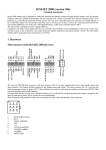
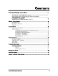
SPARKER TCIP4 version 88 SPARKER TCI-P4 is an ignition unit for road motorcycles. The ignition principle is inductive. The unit is programmable through PC. The device is fully adjustable regarding the ignition timing. It contains ignition advance curve / map depending on RPM and position of throttle or underpressure in the intake manifold. The ignition also contains outputs for tachometer, two multifunctional outputs, two multifunctional inputs, outputs and an input to the servomotor exhaust throttle. The unit is also equipped with racing features - function switch for quick-shifting and output for the shift indicator light. When programmed the unit is connected with computer via serial port. TCIP4.EXE configuration software is included. Standard version has two channels (the unit is marked 2CH - for motorcycles with maximum two induction coils). Full version is a four-channel type (the unit is marked 4CH - motorcycles with maximum four induction coils) with a driver for servomotor exhaust throttle. Both versions of the unit are produced in several further modifications related to the inputs for engine position sensors. The inputs for position sensors are two and each of them can be custom-made in the following versions: 1) For inductive sensor (marked IND or unmarked) 2) For inductive sensor with a pulsed rotor with more than 12 protrusions (labelled 24-2) 3) For inductive sensor with a pulsed rotor with more than 36 protrusions (labelled 48-2 or 60-2) 4) For HALL sensor or optical sensor (marked HALL) HARDWARE Pickup system of the engine position The ignition unit can be used for almost all known and still unknown motor position pickup systems. You can set semisynchronous systems (picking up crankshaft position) and fully synchronous systems (picking up both crankshaft and camshaft positions). Most of the systems can be chosen directly by selecting relevant motorcycle type from the list included in TCIP4.EXE program. Different pickup system can be set following a special procedure in TCIP4.EXE software. Supply voltage +12 V input The supply voltage must be between 8-18 V. In this range the unit is able to provide optimal control of all the processes. Under 7 V and 18 V the unit stops controlling the coils. Supply voltage is connected by positive outlet to +12 V (pin 13) and by negative outlet to GND (pin 14). Outputs 14, 16 and 7 are interconnected in the unit. They can all be used either to connect the power (power supply) ground or to connect the sensors. We don’t recommend the connection of sensors with power (power supply) ground. Input for the engine load sensor The input for engine load sensor can be realized by the throttle position sensor (TPS) or by intake air pressure sensor (IAPS). An input is ready for standard TPS or IAPS sensors used on motorbikes. It is designed to bear voltage up to 5 V. Setting up the voltage levels of the sensor for 0% and 100% or 0-999 kPa is included in TCIP4.EXE software. TPS or IAPS are powered by reference voltage +5V (pin 7) and SENSE GND (7 or 16). Sensor outlet will be connected to connector (6). Crankshaft position sensor CKPS An input is ready for standard inductive pickup sensors used on motorbikes as CKPS. On request, we can also deliver inputs for HALL type sensors. One outlet of the CKPS will be connected to connector (9) and the other outlet will be connected to SENSE GND (7 or 16). In double-pickup systems the other sensor's one outlet will be connected to connector (20) and the other outlet will be connected to SENSE GND (7 or 16). In the case of HALL type sensor the sensor can be powered by +5 V reference voltage (pin 17). Multifunctional inputs The unit contains two multiuse inputs. The inputs can be assigned different functions (KILL switch, CLUTCH MASTER, BLOCKING - for side stand switch, RETARD, START LIMITER). One outlet of the multiuse input 1 will be connected to connector (8) and the other outlet will be connected to GND (14). One outlet of the multiuse input 2 will be connected to connector (19) and the other outlet will be connected to GND (14). Outputs for induction coils IC 1, 4 and IC 2, 3 One outlet of the induction coil IC 1 will be connected to connector (pin 1) and the other one will be connected to the switched +12 V. One outlet of the induction coil IC 2 will be connected to connector (pin 10) and the other one will be connected to the switched +12 V. 1 One outlet of the induction coil IC 3 will be connected to connector (pin 2) and the other one will be connected to the switched +12 V. One outlet of the induction coil IC 4 will be connected to connector (pin 11) and the other one will be connected to the switched +12 V. Dwell mode of the ignition coils can be set to short/long/manual/auto using TCIP4.EXE program. When setting up the dwell it is necessary to check whether the used induction coil is suitable for the chosen configuration. Short dwell is generally used for ignition coils with primary coil resistance less than 2 Ohm. Long dwell time with these ignition coils can result in their destruction. On the contrary, if short dwell time is used for coils that need long dwell time, the energy of spark could be reduced especially in high RPM. You can also set the dwell time manually or automatically for specific induction coil. For more details see the Software section. Revolution indicator output TACHO The RPM indicator output is compatible with most on-board devices used on motorbikes. Number of pulses per one revolution and possible corrections are set using TCIP4.EXE software. TACHO is supplied by 12 V voltage GND. TACHO output will be connected to connector (15). The revolution indicator output is not compatible with on-board devices used on old Honda motorcycles from the 1990s (ignition units with OKI 16pin connector). TCIP4 unit can be equipped with revolution indicator output compatible with these on-board devices on request with surcharge. Power output Powerout 1 Load for Powerout 1 is connected to pin connector (pin 3) and the other outlet to switched +12 V. Output Function is optional, see Power Out tab. Power output Powerout 2 Load for Powerout 2 is connected to pin connector (pin 12) and the other outlet to switched +12 V. Output Function is optional, see Power Out tab. Outputs and input for SERVO Servo outputs and input are compatible with most of servomotors used on motorbikes for exhaust throttle (e.g. Yamaha EXUP). The unit is equipped with servo control only in the full (4-channel, 4CH) version. Required dependency of servo position on RPM and engine load can be configured in TCIP4.EXE program. Servomotor outputs are on pins (4) and (5). Power supply for servo position sensor is connected to +5 V pin (17) and SENSE GND (7 or 16). The output of position sensor is connected to corresponding input (18). Connector adapter For many motorcycles we manufacture so-called connector adapter. This is a short bundle, on one side equipped with a connector fitting into TCIP4 unit and on the other side equipped with a connector fitting the original ignition unit. This connector adapter provides plug and play connection possibility with the original cable harness. In the connector adapters we use the colours of the wires listed in the following table describing various pins of the unit's connectors. Wire colour Orange Yellow/black Purple Green Green Grey Blue or light blue Black Yellow White Red/black Blue/white Red Blue Green/yellow Blue or light blue White/red White/blue Grey/red Brown Connector pin number 1 2 3 4 5 6 7 8 9 10 11 12 13 14 15 16 17 18 19 20 Name IC 1 IC 3 Power out 1 M M TPS, IAP GND, SENSE GND INPUT 1 CKPS 1 IC 2 IC 4 Power out 2 +12 V GND TACHO SENSE GND +5 V STPS INPUT 2 CKPS 2 2 Description Induction coil 1 Induction coil 3 Multifunction output 1 Servomotor output Servomotor output Engine load sensor GND, SENSE GND Multifunction input 1 Crankshaft position sensor 1 Induction coil 2 Induction coil 4 Multifunction output 2 Power supply 12 V Ground Revolution indicator output Sensor ground Power supply of sensors Servo position sensor Multifunction input 2 Crankshaft position sensor 2 Recommended connection diagram 3 TCIP4.EXE software Pull down menus File - includes items: New - Default data setting New for current tab - Default data settings only for the current tab. Open - Opens data file. Open from exe dir - Opens data file from the same directory as the control software. Open for current tab - Opens data file for the current tab only. Save - Saves data file. Save to exe dir - Saves data file to the same directory as the control software. Nine last opened data files Print - Prints current settings of the current tab. Exit - Exits the program. Clicking New results in automatic default settings of all parameters. These correspond to four-cycle engine without TPS. Port - includes items Com 1 to Com 30 and COM Auto to select the communication line. For PCs without serial port (USB only) it is necessary to use USB/RS232 adapter. Ignition - includes items Read Verify Program Reset - Reads data from the unit. - |Compares data in PC with data in the unit. - Sends data to the unit and performs verification. - Resets the unit. Tools – includes tools to set the advance. Language - language settings: English, Czech, German Help - includes items Help About the program - Opens Assembly guide (this file). - Information on the software (version, date). Icons menus Sets default values. Warning!!! Clicking this icon results in automatic default settings of all parameters. Opens data file. Saves data file. Prints the current settings. Tools for going back or forward step by step when changing the settings. See pull down menu Ignition. Tab sheet Miscellaneous Limiter Start limiter Clutch master time Clutch master pause Advance reduction - RPM limiter value settings. - Start limiter value settings. - Sets ignition switch off period during gear shift. - Sets time of clutch master insensitivity after gear shift. - Sets the value for ignition advance retard if the function is active. 4 RPM without ignition - Sets the number of starting revolutions without ignition. For a kick start system this value represents the number of revolutions when all channels ignite together. Dwell - Sets dwell mode of induction coils. Short - For coils with resistance lower than 2 Ohm. Dwell time 1 ms with the dynamic addition 12%. Long - For coils with resistance higher than 2 Ohm. Dwell time 3 ms with the dynamic addition 12%. Manual - Possibility to manually configure the excitation time. Auto - Automatic dwell time determination. The unit itself determines optimal dwell time by measure dynamic current in channel 1. With this choice the ignition coil has to be connected to channel 1. Dwell time - Dwell time required with manual settings [s]. Dwell correction - Automatically determined dwell time can be corrected by percentage [%]. Dynamic dwell addition - Dwell addition to compensate uneven engine running at low RPM [%]. Max. dwell time - Dwell time limitation, including dynamic addition [s]. Min. spark time - Minimum unchangeable spark duration [s]. Max rpm for dwell by lobe - Determination of the revolutions into which the ignition uses the starting sequence of dwelling the coils(excitation by a fixed angle given by a virtual lobe. This virtual lobe is defined in the settings of the pickup system (see tab Bike). Inputs for neutral and side stand - Logic of neutral and side stand inputs is set so that BLOCK function is activated when both inputs are used (if at least one multifunction input is grounded, the bike is not blocked). Input 1, 2- multifunctional Off - No function. Kill switch - When input is grounded - the unit will block ignition. Blocking - When input is not grounded - the unit will block ignition. Clutch master - Quickshifter - function to interrupt the ignition when shifting - when input is grounded. Clutch master inv. - Quickshifter - function to interrupt the ignition when shifting - when input is not grounded. Advance reduction - when input is grounded – the unit decreases the ignition advance by preset value. Start limiter - when input is grounded - unit changes RPM limiter to preset value. Sensor None TPS IAPS - Here you can find the selection of engine load sensor. - No load sensor is in use. - Potentiometer is used as sensor, which picks up the angle of the throttle opening. - Absolute pressure sensor in the intake manifold is used as sensor. TPS sensor - Here you can set the limit values of the TPS voltage [mV] when used as a load sensor. By pushing it measures and sets 0% TPS (supply on, unit connected with PC, no gas). By pushing it measures and sets 100% TPS (supply on, unit connected with PC, full gas). IAP sensor - Here the characteristics of sensor of absolute pressure in the intake manifold is set entering two points, when used as a load sensor. No reading - Reading is not allowed (after programming with this option data cannot be retrieved from the unit). Motorbike tab Motorcycle type - Engine position sensor system selection for specific motorbike. Revolution indicator output Number of pulses per revolution - Basic tachometer output settings. Corrections - Percentage corrections of tachometer values [%]. Sensor polarity - Sensor polarity selection (Plus/Minus/Auto). Plus - Designed for pickup connection, where - as the pulse lobe is getting near to the sensor, it generates positive voltage, and when the lobe is moving away it generates a negative voltage. Minus - Designed for pickup connection, where - as the pulse lobe is getting near to the sensor, it generates negative voltage, and when the lobe is moving away it generates a positive voltage. Auto - Unit itself determines correct polarity automatically (the algorithm is based on the assumption that the sum of pulse lobe angles is lower than the sum of gaps in between). Pickup interchange - Interchanges the engine position sensor inputs (pins 9 and 20). 5 No polarity check - The unit controls polarity of the sensor using shape of the signal. If the actual polarity of the sensor is different from the selected one, the unit will block ignition. This option cancels the blocking of ignition. Interlock input - This option works only for pickup system 1 lobe, 2 pickups. With elevated levels of electromagnetic interference (e.g. at the time of ignition) on some motorcycles (e.g. Ducati) unwanted activation of the pickup input may occur, especially that input which at the moment is not active. This option prevents unwanted activation blocking input 2 during activation of input 1, and vice versa: blocking input 1 during the activation of Input 2. This option, however, may cause problems, when combined with automatic determination of sensor polarity. Spark possible before lobe - During standard operation of the unit ignition can take place only in the section after the start of the virtual lobe. This option allows to burn even before the virtual lobe. Unfortunately this is at the cost of the virtual lobe being 360 °, which significantly affects the accuracy of ignition especially at low revolutions. Lower advance at start - This option decreases (moves) advance to the next start pulse edge compared to the standard starting position in advance. Valid only for starting speed (speed less than 500 RPM). This option can be used especially for large volume single-cylinder engines to prevent kick-back when starting el. starter. You can use this option only for some pickup systems. Special dwell at start - This option can be used to reduce the current load on the ignition coils when starting for pickup systems where the virtual lobe is too wide. As a standard the unit in starting revolutions excites the ignition coil from the start of the virtual lobe to the ignition at the end of the virtual lobe. With this option the dwell starts at the end of the virtual lobe, gives 2 ms and then ignition takes place. Valid only for starting speed (speed less than 500 RPM). This option partially reduced advance for the starting speed (due to delay of 2 ms). Compensation - Frequency compensation of the phase error of engine position inputs. The phase error is due to the frequency dependency of trigger level of input and the delay that occurs when processing the input signal. The phase error is mainly dependent on the number of lobes of the pickup system of the motor position. On the bottom left of this tab there are some statistical data collected from the unit. These data are read out even in the case when the version of the unit control firmware and software are not compatible. It is sufficient when the connection is established and active. The following data are read: The name of TCIP4 unit, firmware version date, number of programming sessions. Description of synchronization - Here the current pickup system can be modified, or new one created (only when selecting Special settings in the Motorbike type menu). Each item allows you to define the so-called Virtual pulse lobes. The virtual pulse lobe can be either a single pulse lobe or a sequence of several pulse lobes and spaces between them. BEWARE: only for very experienced users. Please consult with us any atypical configurations of pickup systems. Advance map tab Advance map The advance map contains up to 10x10 adjustable points depending on revolutions and the engine loads (TPS or IAP) value. If no load map is used, the advance map becomes just a 10-point curve of advance depending on the revolutions. Setting of the advance map (curve) can be done in several ways. - By writing individual values directly into the edit boxes of the PC keyboard. - By using graphic tools up / down arrow (always to the right from the value of the edit field). - Using +/- buttons. This option allows you to change only the current edit box in the engine running mode(the active field is green) or when ALL option is activated the entire map (curve) can be moved in both running and off modes. - By pressing F4 and F5, F4 has the same function as the button "-" and F5 has the same function as the button "+". - Using the scroll wheel of the mouse – by tapping the edit box the option to change by scrolling is activated. - In display mode of the advance map TAB and 2D it is also possible (using the mouse) to pull individual points of the curve. Base advance - Is the angular difference between the position when the crankshaft position sensor is directed to the end of the virtual pulse lobe pulse and the top dead centre position (see angle "base advance" in the picture below). This value is always determined by the mechanical constitution of pickup system and shall never be changed by software settings!!! The field "Base advance" thus is not there to change the base advance: into this field the value must be entered that corresponds to the physical condition of the engine. To the first point of the revolution of advance curve the unit ignites on the value of base advance (at the end of the virtual pulse lobe). The exception is the "Start of lobe system" that can ignite at the beginning of the of the virtual pulse lobe. Therefore for revolutions lower than the first point of advance curve early ignition point cannot be set, as it is derived from the mechanical design of the pickup system!!! The first revolution point of the curve in most cases should be chosen above idle speed!!! Please contact us in case of any uncertainties regarding the design of the pickup systems and their functioning with TCIP4 unit. 1 BASE ADVANCE Correction - Correction of the advance of individual cylinders [°]. Power Out tab Power Out Mode Off - The output is not active. Fuel pump - To control the fuel pump relay, after the ignition is activated for 4 s, when engine running always connected to ground. Gear shift indicator - Control of the gear shift indicator, after reaching the preset engine RPM the output switches to ground. Special - To control specific devices (pair valve Powerjet). The output is switched to ground according to truth table (marked cell) after the comparison limits derived from values on table axes are exceeded. Servo tab Servo on - Software activation of servo controller. Map of positional requirements - of servo controller has up to 10x10 adjustable points depending on revolutions and engine load (TPS angle or the pressure in the intake manifold IAP. If no load map is used, the map becomes only (up to) 10-point curve. The requirement for the position of the servo controller has two modes. Voltage (option "percent" is not checked) - the servo controller searches for the calculated voltage resulting from the map (or curve). After the ignition is switched on the unit checks the servo controller so that it must find the highest and lowest required voltage value, which is located on the map (or the curve) of voltage requirements. When these voltage values are not found (whether due to mechanical obstructions or due to wrong settings), the servo is shut down. 2) Percent (option "percent" is checked) the servo controller searches for the calculated percentage values resulting from the map (or the curve). After the ignition is switched on the unit finds (through mechanical stops - must be available!!!) lower position, which is marked as 0% and the upper position, which is marked as 100%. The servo controller then moves between these points according to calculated current requirements. 1/P[mV] - This is the voltage deviation from which there is linear decrease of the performance of the servo controller towards the required value. Size must be set so that the engine does not tremble and at the same time it must have the smallest regulation deviation. In practice 100 - 600 mV. BEWARE - in case you set too low value there is a risk of servo oscillation. Off [mV] - Voltage deviation from which the servo is completely switched off towards the required value of servo position. In practice 5-50 mV. Tests tab Here you can manually perform some actions that are used to test the outputs of the unit. Ignition - Test of individual ignition outputs. Servo - Test of servo outputs (both directions). The parameter Time specifies the time period during which the servo test is carried out. RPM - Test of tachometer output. Revolutions parameter specifies the revolutions with which the output will be tested. Powerouts - Test of multi-function outputs 1 and 2. 1 Monitor The monitor is located in lower right section. Sensor values and engine's operational characteristics can be observed here. Should there be No connection with PC prompt displayed in the upper right corner, the unit is not connected, switched on, or it correct COM port is not selected. File Programming after a change RPM TP ADVANCE 1 to 4 Sensor 1 Sensor 2 U Servo required Servo measured Blocking Clutch master Advance reduction Start limiter Kill switch Power out 1 Power out 2 COM Dwell Dwell opt. - Complete path of the data file. - Automatic programming settings (after every change). - Engine revolution [1/min] - Throttle position [%] - Current ignition advance of individual cylinders [°]. - Sensor 1 operation signal. - Sensor 2 operation signal. - Supply voltage [V]. - Required value of servo position sensor. - Measured value of servo position sensor. - Unit off signal when blocking selected. - Clutch master activation signal. - Advance reduction activation signal. - Start limiter activation signal. - Unit off signal when killswitch selected. - Signal: switching on the multifunction output 1. - Signal: switching on the multifunction output 2. - Signal of currently used communication port. - Real time of induction coil excitation (including the dynamic addition or during startup sequence). - Optimum time of induction coil excitation determined automatically (without the dynamic addition). 1