1
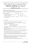
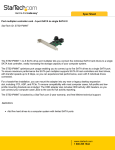
TV5
12 Month Limited Warranty
OWNER’S MANUAL
Audiovox Electronics Corporation (the company) warrants to the original purchaser of this
product that should this product or any part thereof, under normal use and conditions, be
proven defective in material or workmanship within 12 months from the date of original
purchase, such defect(s) will be repaired or replaced with reconditioned product (at the
company’s option) without charge for parts and repair labor. To obtain repair or
replacement within the terms of this warranty, the product along with any accessories
included in the original packaging is to be delivered with proof of warranty coverage (e.g.
dated bill of sale), specification of the defect(s), transportation prepaid, to the company at
the address shown below. DO NOT RETURN THIS PRODUCT TO THE RETAILER.
The warranty does not extend to costs incurred for the installation, removal or
reinstallation of the product.
The warranty does not apply to any product or part thereof which, in the opinion of the
company, has suffered or been damaged through alteration, improper installation,
mishandling, misuse, neglect, accident, or by removal or defacement of the factory serial
number/bar code label(s). THE EXTENT OF THE COMPANY’S LIABILITY UNDER THIS
WARRANTY IS LIMITED TO THE REPAIR OR REPLACEMENT PROVIDED ABOVE AND, IN NO
EVENT, SHALL THE COMPANY’S LIABILITY EXCEED THE PURCHASE PRICE PAID BY
PURCHASER FOR THE PRODUCT.
This warranty is in lieu of all other express warranties or liabilities. ANY IMPLIED
WARRANTIES, INCLUDING ANY IMPLIED WARRANTY OF MERCHANTABILITY, SHALL BE
LIMITED TO THE DURATION OF THIS WARRANTY. ANY ACTION FOR BREACH OF ANY
WARRANTY HERUNDER INCLUDING ANY IMPLIED WARRANTY OF MERCHANTABILITY
MUST BE BROUGHT WITHIN A PERIOD OF 18 MONTHS FROM DATE OF ORIGINAL
PURCHASE. IN NO CASE SHALL THE COMPANY BE LIABLE FOR ANY CONSEQUENTIAL
OR INCIDENTAL DAMAGES FOR BREACH OF THIS OR ANY OTHER WARRANTY. No person
or representative is authorized to assume for the Company any liability other than
expressed herein in connection with the sale of this product.
Some states do not allow limitations on how long an implied
warranty lasts or the exclusion or limitation if incidental or
consequential damage so the above limitations or exclusions
may not apply to you. This warranty gives you specific legal
rights and you may also have other rights that vary from
state to state.
For customer service and
technical information:: 1.800.290.6650
For Customer Service
Visit Our Website At
www.terk.com
Product Information, Photos,
FAQ’s, Owner’s Manuals
and
TERK and the TERK logo are registered trademarks of AUDIOVOX Corp.For customer service
58P008B
technical information::
Audiovox Electronics Corporation, 150 Marcus Blvd., Hauppauge, NY 11788
1.800.290.6650
TV5
Indoor Amplified Television Antenna
About Your TERK TV5
TV5
3
media
media
antenna
on
67
5
8
9 10
6. Amplifier On/Off
Switch
7. Video Selector Switch
8. Amplifier Adjust
9. DC Power Input
10. Video Input
1. Receiving Elements
2. Center Cap
3. Coaxial Cable
4. Center Control Arm
5. Antenna/Video
Power Indicators
antenna
on
media
Assembly:
Assembly of your TV5 is easy. Simply insert the receiving
elements into the center control arm and hand-screw
the center cap, making sure you have a snug fit.
See Fig 1.
Built-In Video Selector Switch:
The TV5 offers the added convenience of a built-in video
selector switch, creating a one cable solution for a video
game, DVD player, VCR or other video component. With
just a push of a button, you can now switch between TV
and another video source without having to disconnect
and reconnect any wires.
1
2
4
Amplified Indoor Antenna:
The TV5 features a fully adjustable, low-noise amplifier,
that is designed to optimize signal strength for any
location. TERK’s patented amplifier bypass allows
stronger local stations to bypass the amplifier entirely,
preventing overmodulation and ensuring successful
reception of the maximum number of available channels.
NOTE: Some video sources may require additional equipment due to incompatible outputs. One of TERK’s Modulators
will allow these components (DVDs, video games, etc.)
that have RCA outputs, to be connected to your TV5.
1
antenna
on
TV5
Thank you for choosing the TERK TV5. TERK antennas are
designed to help deliver sharp, clear video reception. Our
engineering department is dedicated to designing
antennas that enhance both the latest technology and the
aesthetics of any viewing environment. The TV5 installs in
minutes, is easy to use and simple to adjust. Before using
your antenna, please remove all parts from the box and
read the owner’s manual carefully.
Assembly And Installing Your TV5
UHF
Band
Separator
2
VHF/UHF
VHF
media
antenna
on
Fig. 1
Fig. 2
Fig. 3
Installation
Operating Your TERK TV5 LowProfile Indoor Amplified Antenna
(continued)
TV5
TV5
Connecting your TV5
There are two ways to connect your TV5. This will depend
on your model of television.
For Televisions with One 75 Ohm Input for VHF and UHF:
1. Connect the coaxial cable from your TV5 to the
“F” connector input marked VHF/UHF on your TV.
See Fig 2.
For Video Games and Other Video Components:
1. Attach the coaxial cable from your satellite, cable, or
video game adapter to the video input on your TV5.
Ensure a tight fit to avoid interference.
2. Switch the video selector switch to “Video” for operation.
3. To connect a DVD player, VCR or video game system to
a television that is not equipped with A/V jacks, you will
need to obtain one of TERK’s RF modulators.
For Televisions with Separate 75 Ohm
VHF and UHF Inputs:
1. Attach the band separator (not included) to the coaxial
cable attached to the back of your TV5.
2. Screw in the VHF connector from the band separator to
the VHF input on your TV or VCR.
3. Attach the 300 ohm twin wire from the band separator
to the two screws marked UHF. See Fig 3.
Powering your TV5
Attach the AC adapter (included) to the DC input on the
rear of your TV5. Plug the other end of the adaptor into
any 12 volt AC outlet.
3
For VHF and UHF:
1. Switch video selector switch to “Antenna”.
2. Tune your TV to the desired station.
3. Holding the top of the center control arm, simply
rotate the antenna to seek the best quality picture.
4. Adjust the “amplification”slider for the best picture
and sound
4
Operating Your TV5
Frequently Asked Questions
(continued)
TV5
TV5
Please Note:
1. Do not force the center control arm past its normal
rotation positions.
2. Do not place your TV5 near large metal objects or
appliances that would create interference.
2. Do not lift your TV5 by its receiving elements or place
objects on them.
4. Late model televisions have on-screen menu controls
for viewing VHF/UHF “Off-Air” or cable broadcasts.
Please ensure that this menu control is at the proper
“Off-Air” position.
Locating Your TV5
Your TV5 is a precision instrument and should be
placed in a location that is best for receiving TV signals.
Your TV5 can be placed on top of any standard TV for
ease of adjustment.
Performance Specifications
5
Channels:
VHF: 2-13
UHF: 14-69
Operating Bandwidth: 54 MHz to 806 MHz
Output Impedance: 75 ohms
Dimensions (with elements): 43/4"H x 25"W x 12"D
Amplifier Gain: VHF: 12 dB min
UHF: 6 dB min
6
Q. I have a cable ready TV. Why am I not getting any
channels above 13?
A. The tuners inside of cable ready TVs have two modes.
One mode is for cable and the other mode is for
antenna. When the TV is in cable mode, and you are
using an antenna, you will not be able to receive any
channels above 13. To fix this, simply access the menu
of your TV and switch the TV from Cable/CATV mode to
ANT/AIR mode.
Q. I have my TV in a metal cabinet. Will the antenna work?
A. Any large metal objects will prevent the antenna signal
from reaching the antenna. You must place the antenna
outside of or above the metal cabinet.
Q. My home has aluminum siding/insulation. Where
should I place my antenna?
A. Place the antenna near a window to minimize
interference and improve your reception.
Q. Can I use my antenna in a basement?
A. TV signals cannot penetrate into basement locations
due to their lower elevation.
Please Note:
Other variables, which are not related to antenna
performance, can effect your reception. These include
distance from the source transmitting the desired
station, and man-made and natural conditions.
Example: Obstacles such as buildings between the
transmitting source and your antenna.